

Terratek PTS10U User Manual

10" TABLE SAW WITH STAND
PTS10U
SCIE À TABLE AVEC SUPPORT 10 PO
SIERRA DE MESA CON SUPPORTE DE 10"
User Manual – Please
read and retain for
future reference.
See page 1 Voir page 15 Ver la págeina 30
Guide d’utilisation
– Veuillez lire et
conserver ceguide
pour vous y reporter
ultérieurement.
Manual del usuario –
Por favor lea este
manual y guárdelo para
referencia futura.
CM
L
I
S
T
E
D
CUS
3150598
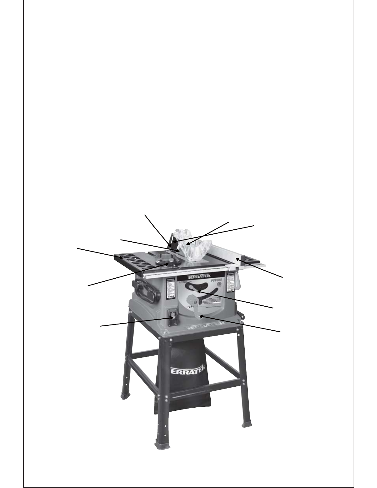
Table Saw
Structure
1. Table top
2. Blade
3. Safety guard
4. Anti kick back fingers
5. Wood splitter
6. Sliding miter guide
7. Adjustable ripping fence
8. Blade height adjustment
wheel
9. Blade angle lock lever
10. On / Off Switch
2
4
1
6
10
8
9
7
5
3
Composants de
la scie à table
1. Plateau
2. Lame pour couper le bois
3. Protège-lame
4. Ergots antiretour
5. Fendeuse à bois
6. Guide d’onglets coulissant
7. Guide de refente réglable
8. Molette de réglage de
hauteur de lame
9. Levier de blocage d’angle
de lame
10. Interrupteur marche-arrêt
La tabla vio la
estructura
1. Sobremesa
2. Cuchilla
3. Guardia de la seguridad
4. Anti golpeen detrás los dedos
con el pie
5. Divisor de madera
6. Deslizar la guía del inglete
7. Cerca de rasgadura ajustable
8. Rueda del ajuste de altura de
cuchilla
9. Palanca de la cerradura del
ángulo de cuchilla
10. Interruptor con./desc.

.QO
.QO
Packing Contents
Contenu de la boîte d’emballage
Contenido del embalaje
1. Machine Body
2. Ripping Fence Assembly
3. Sliding Mitre Fence
4. Safety Blade Guard
5. Wood Cutting Saw Blade
6. Blade Changing Key
(Spanners) x 2
7. Hex Key
8. Push Stick
9. Blade height adjustment
knob
1. Bâti
2. Ensemble guide de refente
3. Guide d’onglets coulissant
4. Protège-lame
5. Lame pour couper le bois
6. Clé pour changement
de lame (2)
7. Clé hexagonale
8. Poussoir
9. Molette de réglage de
hauteur de lame
1.Cuerpo de máquina
2.Rasgadura del montaje de
la cerca
3.Desplazamiento de la cerca
del inglete
4.Guardia de cuchilla de la seguridad
5.Cuchilla de sierra para madera
6.Llave cambiante de la cuchilla(2)
7.Liave hexagonal.
8.Impulsor
9.Botón del ajuste de altura
de cuchilla
1. Long Top Rails
2. Short Top Rails
3. Long Lower Support Rails
4. Short Lower Support Rails
5. Legs
6. Rubber Feet
7. Leg stand nuts and bolts
1. Traverses supérieures longues
2. Traverses supérieures courtes
3. Traverses inférieures longues
4. Traverses inférieures longues
5. Pattes
6. Pieds en caoutchouc
7. Écrous et boulons pour support
1.Carriles superiores largos
2.Carriles superiores cortos
3.Carriles superiores largos
4.Carriles superiores cortos
5.Piernas
6.Patas de cancho
7.Tuercas y pernos del soporte.
Leg Stand Support Leg Stand
.QO .QO
.QO .QO
.QO .QO
126
127
(Short)
(Short)
(Iong)
(Iong)
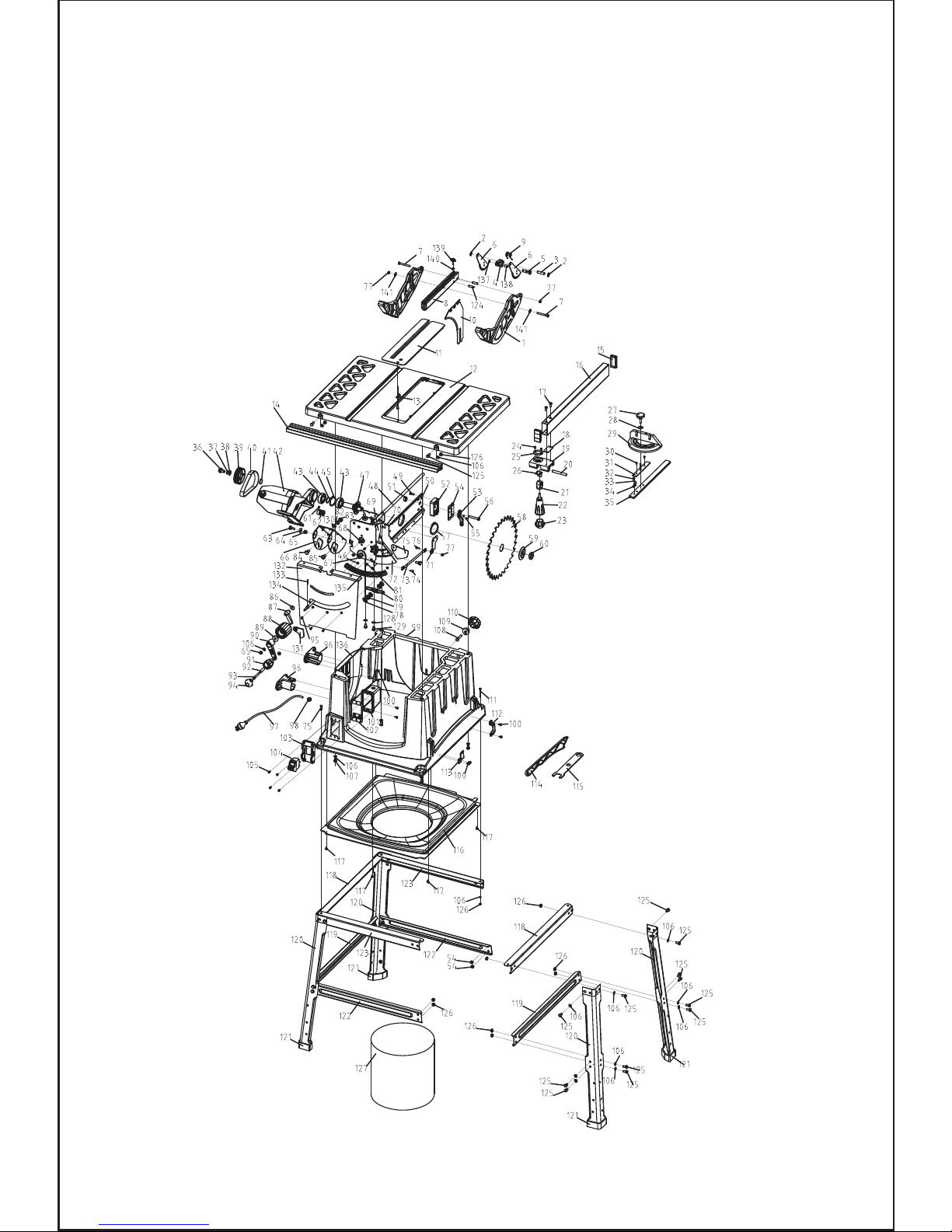
Exploded Assembly Diagram
Vue éclatée
Dibujo despiezado del conjunto

1
Parts List
1
2
3
4
5
6
7
8
9
10
11
12
13
14
15
16
17
18
19
20
21
22
23
24
25
26
27
28
29
30
31
32
33
34
35
1
2
1
1
1
2
2
1
1
1
1
1
1
1
2
1
2
1
1
1
1
1
1
2
1
1
1
1
1
2
1
1
1
1
1
36
37
38
39
40
41
42
43
44
45
46
47
48
49
50
51
52
53
54
55
56
57
58
59
60
61
62
63
64
65
66
67
68
69
70
2
4
1
1
1
1
1
2
1
1
3
1
1
4
1
4
1
4
1
2
1
1
1
1
1
1
1
2
2
2
1
1
1
1
2
Blade guard
Bead flange 8
Cylindrical pin 8×30
Anti-kickback support
Locking shaft
Anti-kickback
Screw M5×45
Guard support
Spring
Riving knife
Table insert
Table
Locking dog
Slide rail
Fence cap
Fence
Cheese head screw M5×10
Plate
Slide carriage
Cardinal axis
Cam
Tension knob
Tension knob cover
ScrewM4×6
Magnifying glass
Tension washer
Nut
Flat washer 6
Angle gauge
Sunken screw M4×8
Angle gauge plate
Screw M4×8
Flat washer 4
Indicator
Angle gauge rod
Cheese-head screw M8×14
Spring washer 8
Flat washer 8
Driven pulley
Poly V-belt
Elastic collar 17
Motor
Bearing 6003-2Z
Dottle pin
Elastic collar 35
Hex nut M4
Shaft assembly
Live shaft assembly
Cheese-head screw M5×12
Riving knife plate
Self-locking nut M8
Riving knife support
Handle
Riving knife pressing plate
Screw M3×4
Hexagon bolt M8×40
Elastic collar 45
Blade
Flange
Nut M16×1.5
Set screw M6×8
Drive pulley
Bolt
Spring/B/12.5
Self locking nut M6
Bracket holder
Gear
Square neck bolt M6×14
Leading track
Screw M5×14
No Description Qty No Description Qty
Contents
Table Saw Structure
Packing Contents
Parts List
Technical Information
Safety Instructions
Assembly
Using your saw
Maintenance
Warranty

2
Parts List
71
72
73
74
75
76
77
78
79
80
81
82
83
84
85
86
87
88
89
90
91
92
93
94
95
96
97
98
99
100
101
102
103
104
105
106
1
1
1
1
1
1
4
2
4
1
6
4
4
2
2
1
1
1
1
1
1
1
1
1
3
2
1
3
1
4
1
1
1
1
2
46
107
108
109
110
111
112
113
114
115
116
117
118
119
120
121
122
123
124
125
126
127
128
129
130
131
132
133
134
135
136
137
138
139
140
141
4
1
1
1
2
1
1
1
2
1
4
2
2
4
4
2
2
2
46
46
1
4
4
4
1
1
1
1
1
1
1
1
1
1
2
Tie bar
Protective plate
Lever
Screw M5×14
Rotating plate
Screw M5×14
Self-locking nut M5
Spring washer
Hex nut M8
Screw shaft
Sunken screw M4×10
Flat washer 8
Hex nut M8
Sunken screw M8×25
Cheese-head screw M8×25
Flat washer 6
Handle
Wheel handle
Washer 6
Rocker arm
Wheel handle
Tube
Slotted cheese-head screw M6×50
Wheel handle
Sunken screw M4×10
cable support
Cable
Cable gland
Box
Tapping screw ST4.2×16
Connection box
Earth plate
Switch plate
Switch
Tapping screw ST3.5×13
Flat washer 6
Hexagon bolt M6×30
Hexagon bolt M6×35
Blade support
Tension knob
Hexagon bolt M6×50
Front clip
Back clip
Push stick
Wrench
Bottom plate
Tapping screw ST3.5×13
Beam
Beam
Leg
Foot
Beam
Beam
Cylindrical pin 5×22
Hexagon bolt M6×12
Hex nut M6
Dust bag
Spring washer 10
Slotted cheese-head
screw M10×20
Spring washer 8
Angle pointer
Front plate
Cylindrical pin 3×20
Threaded rod
Gear rack
Base guard
Split washer 6
Spring
Knob
Square nut M5
Flat washer 5
No Description Qty
No
Description Qty

3
Technical Information
Voltage: 120V~60Hz
Rated Power: 13A
No Load Speed: 5700 RPM
Cutting capacity: 0º/90º: 2-3/4" ;
45º: 2-1/2"
Blade Size: 10"x5/8"
Table size: 26"x17-5/16"
Weight NW/GW: 44/49.7 Lbs
Read this entire manual before using this product.
Failure to do so can result in serious injury. Save this manual
for future reference.
Copyright© 2010 by Terratek Intl Ltd. All rights reserved. This manual or any artwork
contained herein must not be reproduced in any shape or form without the express
written consent of Terratek Intl Ltd. Diagrams within this manual may not be drawn
proportionally. Due to continuing improvements, actual product may differ slightly
from the product described herein.
Important SAFETY Information
This symbol is to warn you of potential personal
injury hazards. Please read carefully the notes along side
this warning to avoid possible injury or death.
General Safety Rules
WARNING! Read all instructions. Failure to follow all instructions listed below may
result in electric shock, fire and/or serious injury. The term “power tool” in all of the
warnings listed refers to corded or cordless power tools.
Work area safety
Read and Keep This Manual
Electrical safety
Before use, ensure that the power outlet you are using matches the plug on your
power tool and that the voltage of the outlet matches that of your power tool.
Only use grounded extension cords with power tools fitted with 3 pin plugs and if
using outdoors ensure any extension cord is suitable for outdoor use.
Always try to avoid body contact with grounded surfaces, such as radiators, cooking
ranges and any other fixed appliance with metal surfaces.
Keep work area clean and well lit. Cluttered or dark areas invite accidents.
Do not operate power tools in explosive atmospheres, such as in the presence of
flammable liquids, gases or dust. Power tools create sparks which may ignite the dust
or fumes
Keep children and bystanders away while operating a power tool. Distractions can
cause you to lose control.
Please read carefully all instructions within this manual. Failure to follow all safety
warnings can result in serious personal injury. The term “Power Tool” in all of the
following warnings refers to your mains operated (corded) or battery operated (cordless) power tool
4

Personal safety
Never use your power tool whilst under the influence of alcohol, drugs or medication.
Tiredness can often cause accidents, stay alert.
Never use your power tool without the correct guards in place.
Always use ANSI approved eye protection and dust mask. Non slip safety shoes and
hearing protectors should be worn at all times when using your power tool.
Ensure any dust collecting device supplied with your machine is connected correctly
before use.
Ensure all loose clothing, long hair or jewelry is kept clear of the machine.
Before plugging your power tool into the power outlet ensure the power tool is in the
OFF position.
Check that wrenches or adjusting keys have been removed. Any wrench or key left
attached to a moving part can result in injury.
Power tool use and care.
Keep your power tool clean and well serviced at all times.
Never adjust or service any power tool before disconnecting from the mains electricity
supply.
Always use the correct tool for the job.
Never force the tool to work harder than it is designed to do.
Never use your power tool with broken parts such as switches, guide fences or leg
stands.
ALWAYS keep your power tools away from children.
Keep cutting tools sharp to ensure less stress on the motor.
Only have your power tool serviced by a qualified repair agent using manufacturers
recommended parts
5
WARNING: For your own safety read Instruction Manual before operating miter saw.
Do not expose your power tool to wet or damp conditions and NEVER use in rain.
Check regularly the power cord of your machine and any extension cord that you are
using for damage.
Do not carry or pull the machine with the power cord.
Ensure the cord is clear from hot surfaces, oil or sharp objects.
A) Wear eye protection.
B) Keep hands out of the path of saw blade.

6
GENERAL SAFETY INSTRUCTIONS
Read this owner's manual completely and make sure you understand all of its safety
guidelines.
1. KEEP GUARDS IN PLACE and in working order.
2. REMOVE ADJUSTING KEYS & WRENCHES. Before turning on the power tool,
make sure the keys and adjusting wrenches have been removed.
3. KEEP WORK AREA CLEAN. Cluttered areas and benches invite accidents.
4. ALWAYS REMAIN ALERT WHEN THE SAW IS IN USE. Inattention on the part of
the operator may lead to serious injury.
5. DON’T USE IN A DANGEROUS ENVIRONMENT. Don’t use power tools in damp or
wet locations or expose them to rain. Keep work area well lit.
6. KEEP CHILDREN AWAY. All visitors should remain at a safe distance from work area.
7. MAKE WORKSHOP CHILD-PROOF with padlocks, master switches or by removing
starter keys.
8. USE THE RIGHT TOOL. Don’t force a tool or attachment to do a job for which it was
not designed.
9. USE THE PROPER EXTENSION CORD. Make sure your extension cord is in good
condition. When using an extension cord, be sure to use one heavy enough to carry
the current your product will draw. An undersized cord will cause a drop in line voltage
resulting in loss of power and overheating. Table (see Table 1) shows the correct
size to use depending on cord length and nameplate ampere rating. If in doubt, use
the next heavier gauge. The smaller the gauge number, the heavier the cord.
10. DON’T FORCE THE TOOL. It has been designed to operate at maximum safety and
performance levels.
11. DO NOT FORCE THE MATERIAL BEING CUT. Always let the tool cut at its own
speed.
12. WEAR PROPER APPAREL. Do not wear loose clothing, neckties, rings, bracelets
or other jewelry which may get caught in moving parts. Non-slip foot wear is reco mmended. Wear protective hair covering if you have long hair.
13. ALWAYS USE SAFETY GLASSES. Also use face or dust mask for commercial
cutting operations. Everyday eyeglasses only have impact-resistant lenses, they
are NOT safety glasses.
C) Do not operate tool without guards in place.
D) Do not perform any operation freehand.
E) Never reach around saw blade. (Or never reach in back of saw blade)
F) Turn off tool and wait for saw blade to stop before moving workpiece or changing
settings.
G) Disconnect power(or unplug tool) before changing blade or servicing

7
This power tool is supplied with all the relevant safety guards and features, it should
be checked before every operation, this manual should be read and kept in a safe place.
Whilst we warn of all the possible risks attached to using power tools any operator must
have read and understood the manual and apply their own caution and common sense
when using this power tool.
Following this guide will greatly reduce your risk of electric shock or injury.
14. SECURE WORK. Use clamps or a vise instead of your hand to hold work when
practical. This safety precaution allows for proper tool operation using both hands.
15. DON’T OVERREACH. Keep proper footing and balance at all times.
16. MAINTAIN TOOLS WITH CARE. Keep tools clean and in good working condition
for maximum safety performance. Follow instructions for lubricating and changing
accessories.
17. DISCONNECT TOOLS BEFORE SERVICING – when changing accessories, such
as blades, bits, cutters, etc.
18. REDUCE THE RISK OF UNINTENTIONAL STARTING. Make sure switch is in
OFF position before plugging in.
19. USE RECOMMENDED ACCESSORIES. Consult the owner’s manual for recom mended accessories. The use of improper accessories may increase risk of injury.
20. MAKE SURE YOU USE THE CORRECT TOOL for the job you are doing.
21. NEVER STAND ON TOOL. Serious injury could occur if the wet saw is tipped or if
the cutting tool is unintentionally contacted.
22. CHECK DAMAGED PARTS. Before further use of the tool, damaged part(s), (i.e.,
guard) should be carefully checked to determine that it will operate properly and
perform its intended function. Check for alignment of moving parts, binding of
moving parts, breakage of parts, mounting and any other condition that may affect
the tools operation. A guard or other part that is damaged should be properly rep aired or replaced.
23. Replace damaged blades immediately. DO NOT USE DAMAGED BLADES. They
may cause bodily injury.
24. DIRECTION OF FEED. Feed work into the blade against the direction of rotation
of the blade only.
25. DO NOT ALTER THE PLUG OR USE A 2-PRONG RECEPTACLE. This saw is
equipped with a 3-prong electrical plug.
26. NEVER LEAVE TOOL RUNNING UNATTENDED. Turn power off. Don’t leave tool
until it comes to a complete stop.
8
Only use qualified repair agents to service this power tool.
Only use qualified electrician to repair any damaged wiring.
NEVER remove the grounding prong from the power toll or extension cord.
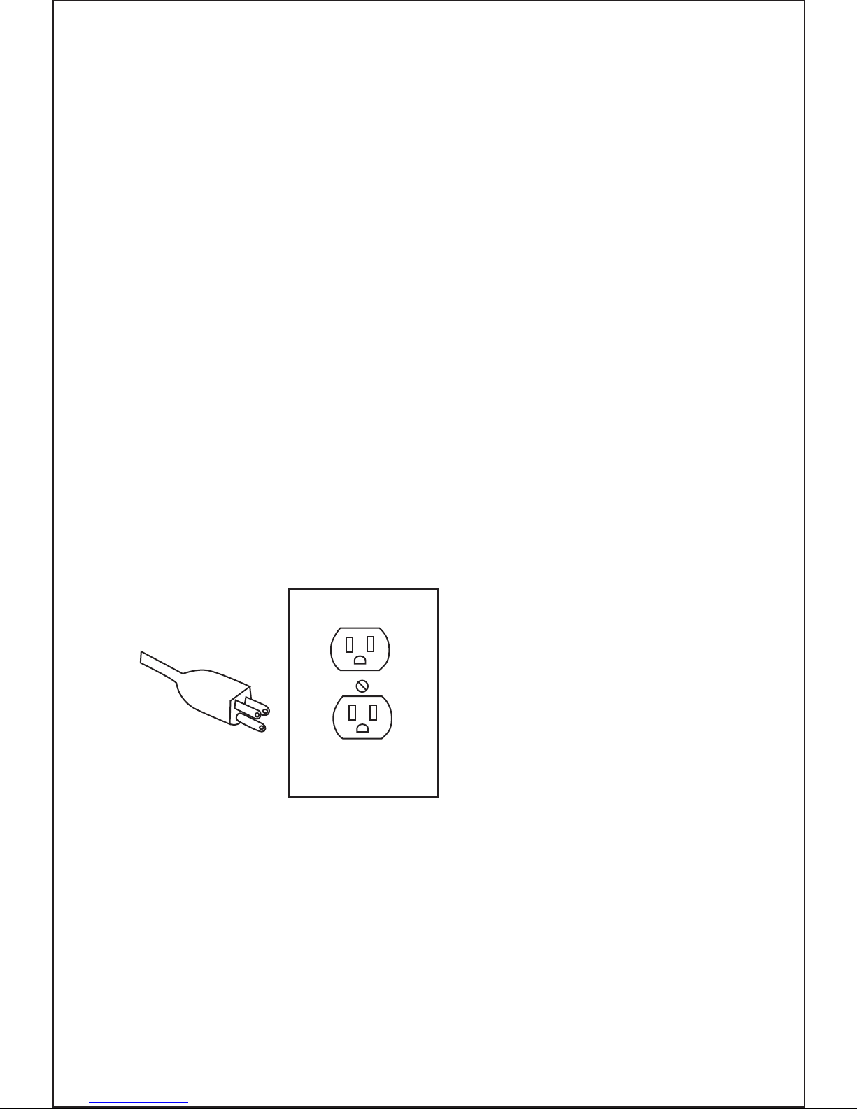
Grounding Tools
Electrical Powered Connections
3-Prong Plug and Outlet
Any electric powered tool that is marked Ground Required must have fitted a three
wired power cord. The main importance of this is the green wire within the cord, this
green wire must at all times be connected to the grounding prong of the plug. This
prong must never be removed or discarded. The green wire Must NEVER be connected to any other prong. The Three prong plug must only be connected to the power
supply through a three prong power outlet.
The Illustration above shows a three prong plug and outlet.
This product must be grounded. In the event of a malfunction or breakdown, grounding
provides a path of least resistance for electric current to reduce the risk of electric shock.
This product is equipped with an electric cord having an equipment-grounding conductor
and a grounding plug. The plug must be plugged into a matching outlet that is properly
installed and grounded in accordance with all local codes and ordinances.
Do not modify the plug provided. If it will not fit the outlet, have the proper outlet installed
by a qualified electrician.
Check with a qualified electrician or service personnel if the grounding instructions are
not completely understood, or if in doubt as to whether the product is properly grounded.
Repair or replace a damaged or worn cord immediately.
This product is for use on a nominal 120 V circuit and has a grounding plug similar to
the plug illustrated in Table1. Only connect the product to an outlet having the same
configuration as the plug. Do not use an adapter with this product.
Grounding Instructions
9
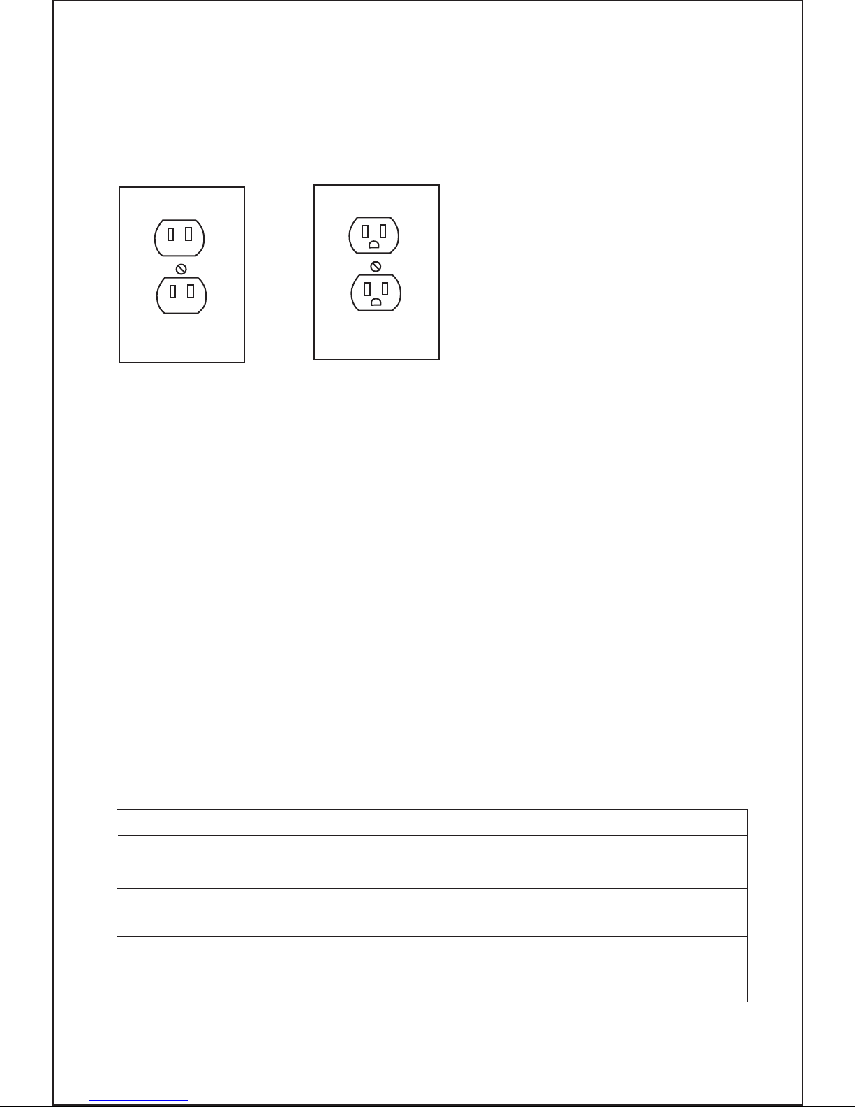
Outlets for 2-Prong Plug
Any electric powered tool that is marked Double insulated only need a two prong
connection and will be perfectly safe to operate.
These tools do not require grounding as they are fitted with an additional insulation
system internally that complies with all relevant electrical safety standards.
Unlike the three prong tools these tools CAN be connected through outlets suitable
for two prong or three prong plugs.
The Illustration above shows the outlets that this type of tool can be connected to.
Power Extension Cords
Any power tool marked ‘Grounding required’ MUST only be connected to a three
wire extension cord. Only double insulated tools can be connected to two wire cords.
When using any extension cord the machine will suffer a power reduction due to
the drop in voltage caused by the length of the cord. This can be partially offset by
selecting extension cords with lower gauge wire.
Double Insulated Power Tools
Plug and outlet, 2 prong
Table 1
MINIMUM GAGE FOR CORD SETS
Total Length of Cord in Feet(Meter)
0-25 26-50 51-100 101-150
(0-7.6) (7.9-15.2) (15.5-30.5) (30.8-45.7)
Ampere Rating
AWG
0 6 18 16 16 14
18 16 14 12
18 16 14 12
14 14
Non Recommended
6 10
10 12
12 16
More Not More
Than Than

10
e.g. Cords marked 14 gauge can carry a higher current than cords marked 16 gauge
therefore when linking extension cords make sure each cords wire gauge matches.
Note: Outdoor extension cords used in must carry the letters “W-A” (USA) or “W”
(Canada)
Check all extension cords for damage before use.
Avoid sharp objects.
Do not position the cord where it could be subject to traffic passing over it.
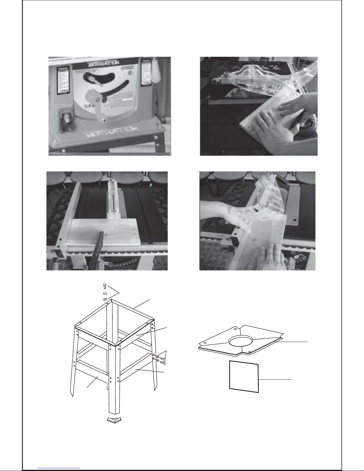
NOTE: Parts of leg stand (Fig.7) have the locating holes for mounting the dust bag
adaptor plate and the saw bench, these holes must be positioned to the top of the leg
stand. During assemble ensure all locking washers are used in the correct position and
that all connecting nuts and bolts are securely tightened.
1. Lay the saw bench top down.
2. Locate the dust collector bag adaptor plate (Pt.116),
3. Add the completely assembled leg stand securing both the leg stand and adaptor
plate to the machine body with the enclosed nuts bolts and locking washers.
4. Once assembled turn the complete machine over so that it now stands on the legs,
this requires two people to avoid injury when lifting.
5. Secure the dust bag (Pt.127) to the dust bag adaptor plate (Pt 116) (Fig.8)
When assembling your machine do not connect to the power supply until you have
fully read and understood this manual. After carrying out all checks and making any
necessary adjustments check that the machine switch is in the off position, connect
to the power supply and then switch the machine on and off quickly, this will allow you
to check for any loose blades or accessories without the machine gaining full speed.
Disconnect from the power supply before attempting any adjustments.
During manufacturing your machine is set and calibrated to cut accurately however
movement can occur during transit. If you find that your machine is not cutting accurately you can make several small adjustments easily.
Assembly
Warning !!
Before Assembly DO NOT CONNECT TO POWER SUPPLY.
Leg Stand Assembly
Mounting the saw bench
Saw Bench Assembly
Carefully remove the product and any accessories from the box. Make sure that all
items listed in the packing list are included.

11
Fitting the Blade’s Safety Guard
Mounting the Rip Fence
Blade height adjustment wheel.
Fitting Sliding Miter Fence
Warning: Always ensure the Rip fence is parallel to the saw blade before use to
avoid blade jam and timber kick back.
Warning. First time use or after changing the saw blade. With the machine DISCONNECTED from the power supply, rotate the blade carefully by hand to ensure
that nothing fouls its operation.
Mounting the blade
1. Ensure the machine is disconnected from the power supply,
2. Remove the screw holding the blade locating plate (Pt.11) in the table top, remove
the locating plate.
3. Rotate the blade height adjustment wheel to lift the motor to its highest position.
4. Remove blade locking nut (Pt.60) and outside blade washer (Pt.59), (Fig.1)
5. Fit blade ensuring blade teeth are facing forward. (Fig.1)
6. Re-fit the blade washer and locking nut using the blade lock keys (spanners) ensu ring that the blade lock nut is tight.
7. Re-fit the blade locating plate with the screw.
1. The safety guard is pre-assembled at the factory.
2. Simply remove the lock nut on the guard locating peg at the rear of the table, slide
the guard support seat (Pt.52) onto the locating peg, refit and retighten the lock nut.
1. Loosen the locking handle
2. Slide the Rip fence onto the table top from the left side of the machine ensuring that
the guides on the rip fence locate into the slide guide. (Fig.2)
The locking handle can be screwed in or out to increase or decrease the tension on
the locking lever.
This wheel adjusts the blade height by turning clockwise, it raises the blade giving a
deeper cutting depth, turning anti clockwise reduces cutting depth. (Fig.3)
Before using, fit the plastic peg to the front of the knob to give more accurate control.
1. Simply slide miter fence into the grooved guide way on the table top.
2. Connect to the power supply, switch the machine on for 2-3 seconds and then turn
off before it runs to maximum speed. (This will confirm that the blade is running free)
Once you have checked that the blade is secure and running free you are able to pr oceed to use the bench saw.
 Loading...