

Terratek PSMS10L User Manual

User Manual – Please
read and retain for
future reference.
See page 1 Voir page 18 Ver la págeina 37
Guide d’utilisation
– Veuillez lire et
conserver ceguide
pour vous y reporter
ultérieurement.
Manual del usuario –
Por favor lea este
manual y guárdelo para
referencia futura.
10” Sliding Mitre Saw
Scie à onglets à coulisse de 10 pouces
Sierra de inglete deslizante de 10
”
PSMS10L
250100
CUS
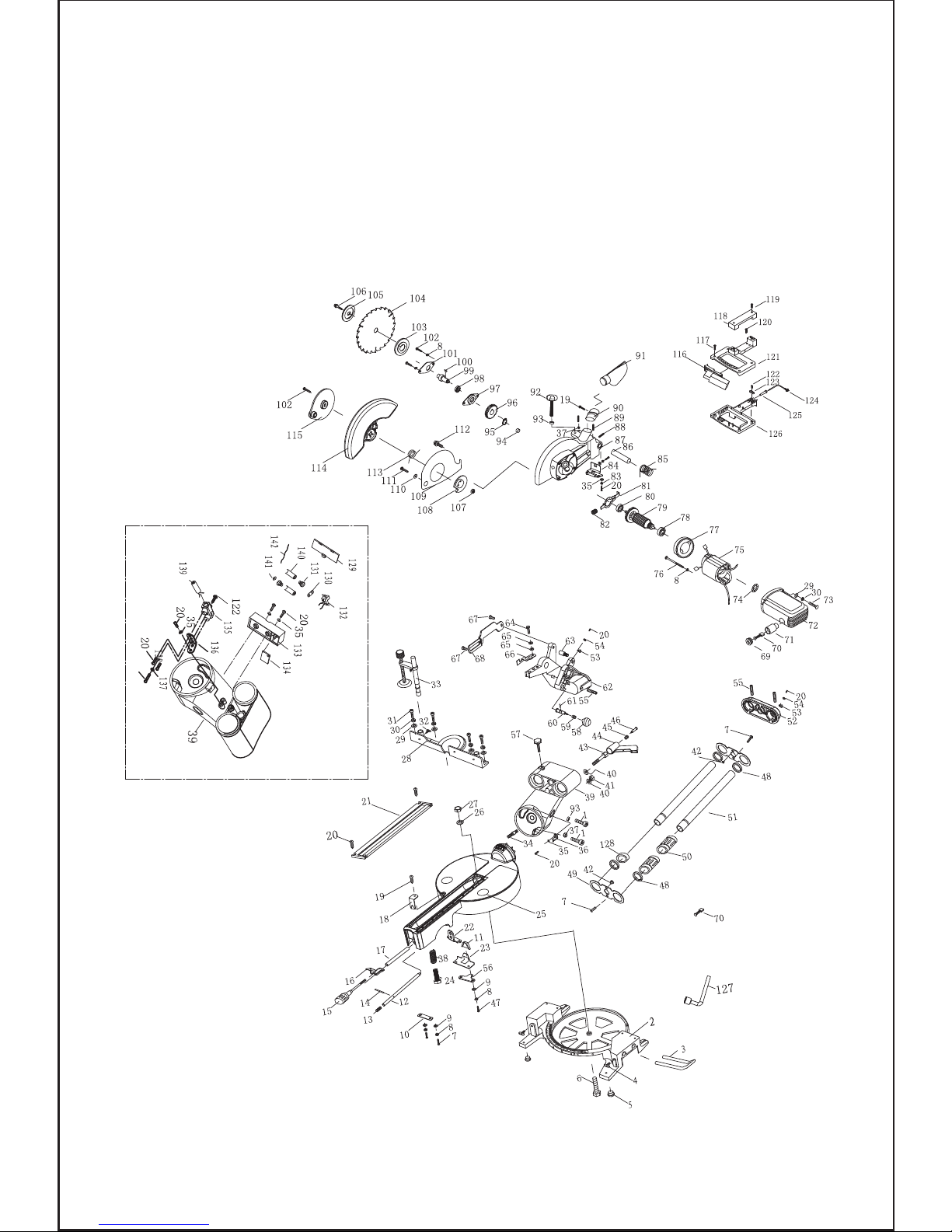
Exploded Assembly Diagram
Vue Éclatés
Dibujo despiezado del conjunto

Fig.1 Fig.2
Fig.3 Fig.4
Fig.5 Fig.6
Fig.7 Fig.8

Fig.9 Fig.10
Fig.11 Fig.12
Fig.13 Fig.14
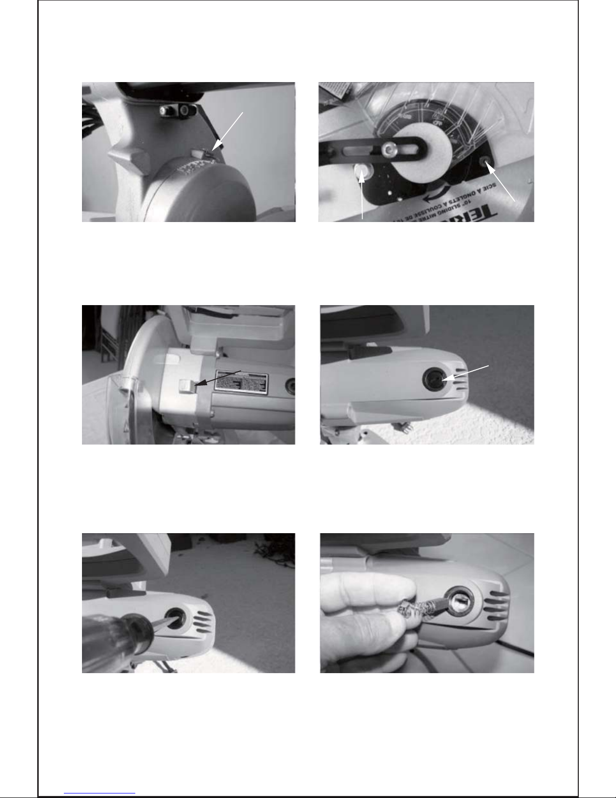
Fig.15 Fig.16
Fig.17 Fig.18
Fig.19 Fig.20

1
Part QtyDescription Part
Qty
Description
Contents
Parts List
Technical Information
Safety Instructions
Using your tool
Maintenance
Warranty
Parts List
1
2
3
4
5
6
7
8
9
10
11
12
13
14
15
16
17
18
19
20
21
22
23
24
25
26
27
28
29
30
31
32
33
34
35
36
Bolt M6X25
Base
Extension Arm
Screw
Feet
Bolt M8X50
Bolt M5X10
Spring Washer
Flat Washer
Plate
Rub Slice
Pin
Spring
Pin 3X20
Mitre lock Handle
Mitre lock button
Pin
Pointer
Bolt M4X12
Bolt M4X8
Kerf
Plate
Plate
Bolt M8X30
Rotation table
Flat Washer
Lock Nut
Fence
Flat Washer
Spring Washer
Bolt M6X30
Lock Screw
Work Piece Clamp
Bolt
Flat Washer
Pointer
2
1
2
2
4
1
4
8
4
1
1
1
1
1
1
1
1
1
2
9
1
1
1
1
1
1
1
1
8
8
4
1
1
1
1
1
37
38
39
40
41
42
43
44
45
46
47
48
49
50
51
52
53
54
55
56
57
58
59
60
61
62
63
64
65
66
67
68
69
70
71
72
Lock Nut
Spring
Bend Arm
Flat Washer
Lock Nut
Washer
Bolt
Bevel Lock Handle
Lock Pin Spring
Bolt
Bolt M5X14
Spacer
Oil Cover
Bearing
Rod
Mount
Line Button
Washer
Bolt M6X10
Limit Plate
Slide lock knob
Release knob
Lock Spring
Lock Pin
Spring Pin
Cover Stand
Screw
Bolt
Washer
Trenching stop
Link Pole Bolt
Link Pole
Brush Cover
Carbon Brush
Brush House
Motor House
2
1
1
2
1
2
1
1
1
1
2
4
2
2
2
1
2
2
4
1
1
1
1
1
1
1
1
1
2
1
2
1
2
4
2
1

2
73
74
75
76
77
78
79
80
81
82
83
84
85
86
87
88
89
90
91
92
93
94
95
96
97
98
99
100
101
102
103
104
105
106
107
4
2
1
2
1
1
1
1
1
1
2
1
1
1
1
1
2
1
1
1
2
1
1
1
1
1
1
1
1
3
1
1
1
1
1
Bolt
Brush House Spring
Stator
Screw
Block Circle
Bearing
Rotor
Bearing
Lock Button
Lock Button Spring
Spring Washer
Block Plate
Spring
Pin
Cover
Bolt M6X10
Bolt M6X20
Dust extraction outlet
Dust Collect bag
Depth Screw
Lock Washer
Bearing
Spring Washer
Gear
Front Cover
Bearing
Output Axis
Key 4X13
Bearing Cover
Bolt
Inner Flange
Blade
Outer Flange
Screw M8X20 Left
Lock Nut
Small Cover
Large Bolt Cover
Washer
Bolt
Bolt M8X12
Spring
Rotation blade guard
Link Pole Plank
Switch trigger
Bolt
Handle
Bolt
Bolt
Operation Handle
Bolt
Press Plank
Power Wire
Rubber sheath
Handle
Hex Spanner
Bearing
battery cover
Plate
spring
switch
battery box
base Plate
laser base
Location plate
nut
bolt
laser head
battery
copper sheet
wire
108
109
110
111
112
113
114
115
116
117
118
119
120
121
122
123
124
125
126
127
128
129
130
131
132
133
134
135
136
137
138
139
140
141
142
Part# Description Qty Part# Description Qty
1
1
1
1
1
1
1
1
1
2
1
2
2
1
2
1
1
1
1
1
1
1
1
4
1
1
1
1
1
1
1
1
2
1
1

Read this entire manual before using this
product. Failure to do so can result in serious injury. Save
this manual for future reference.
3
Copyright© 2010 by ACL Group Ltd. All rights reserved. This manual or any artwork
contained herein must not be reproduced in any shape or form without the express written
consent of ACL Group Ltd. Diagrams within this manual may not be drawn proportionally.
Due to continuing improvements, actual product may differ slightly from the product
described herein.
Technical Information
Voltage: 120V ~ 60Hz
Rated Power: 15A
No Load Speed: 5000 RPM
Blade Size: 10"x5/8"
Cutting Capacity: 0˚/90˚(HxW): 2-3/4"x12"
45˚/90˚(HxW): 1-9/16"x12"
0˚/45˚(HxW): 2-3/4"x8-1/4"
45˚/45˚(HxW): 1-9/6"x8-1/4"
Weight NW/GW: 30/35Lbs
Important SAFETY Information
This symbol is to warn you of potential personal
injury hazards. Please read carefully the notes along side
this warning to avoid possible injury or death.
General Safety Rules
WARNING! Read all instructions. Failure to follow all instructions listed below may
result in electric shock, fire and/or serious injury. The term “power tool” in all of the
warnings listed refers to corded or cordless power tools.
Work area safety
Read and Keep This Manual
Electrical safety
Before use, ensure that the power outlet you are using matches the plug on your power
tool and that the voltage of the outlet matches that of your power tool.
Only use grounded extension cords with power tools fitted with 3 pin plugs and if using
outdoors ensure any extension cord is suitable for outdoor use.
Always try to avoid body contact with grounded surfaces, such as radiators, cooking
ranges and any other fixed appliance with metal surfaces.
Keep work area clean and well lit. Cluttered or dark areas invite accidents.
Do not operate power tools in explosive atmospheres, such as in the presence of
flammable liquids, gases or dust. Power tools create sparks which may ignite the
dust or fumes.
Keep children and bystanders away while operating a power tool. Distractions can
cause you to lose control.
Please read carefully all instructions within this manual. Failure to follow all safety
warnings can result in serious personal injury. The term “Power Tool” in all of the
following warnings refers to your mains operated (corded) or battery operated (cordless) power tool
4

Personal safety
Never use your power tool whilst under the influence of alcohol, drugs or medication.
Tiredness can often cause accidents, stay alert.
Never use your power tool without the correct guards in place.
Always use ANSI approved eye protection and dust mask. Non slip safety shoes and
hearing protectors should be worn at all times when using your power tool.
Ensure any dust collecting device supplied with your machine is connected correctly
before use.
Ensure all loose clothing, long hair or jewelry is kept clear of the machine.
Before plugging your power tool into the power outlet ensure the power tool is in the
OFF position.
Check that wrenches or adjusting keys have been removed. Any wrench or key left
attached to a moving part can result in injury.
Power tool use and care.
Service
Keep your power tool clean and well serviced at all times.
Never adjust or service any power tool before disconnecting from the mains electricity
supply.
Always use the correct tool for the job.
Never force the tool to work harder than it is designed to do.
Never use your power tool with broken parts such as switches, guide fences or leg
stands.
ALWAYS keep your power tools away from children.
Keep cutting tools sharp to ensure less stress on the motor.
Only have your power tool serviced by a qualified repair agent using manufacturers
recommended parts.
Develop a periodic maintenance schedule for your tool. When cleaning a tool be careful
not to disassemble any portion of the tool since internal wires may be misplaced or
pinched or safety guard return springs may be improperly mounted. Certain cleaning
agents such as gasoline, carbon tetrachloride, ammonia, etc. may damage plastic parts.
Have your power tool serviced by a qualified repair person using only identical replacement parts. This will ensure that the safety of the power tool is maintained.
5
Do not expose your power tool to wet or damp conditions and NEVER use in rain.
Check regularly the power cord of your machine and any extension cord that you
are using for damage.
Do not carry or pull the machine with the power cord.
Ensure the cord is clear from hot surfaces, oil or sharp objects.

GENERAL SAFETY INSTRUCTIONS
1. KEEP GUARDS IN PLACE and in working order.
2. REMOVE ADJUSTING KEYS & WRENCHES. Before turning on the power tool, make
sure the keys and adjusting wrenches have been removed.
3. KEEP WORK AREA CLEAN. Cluttered areas and benches invite accidents.
4. ALWAYS REMAIN ALERT WHEN THE TOOL IS IN USE. Inattention on the part of
the operator may lead to serious injury.
5. DON’T USE IN A DANGEROUS ENVIRONMENT. Don’t use power tools in damp or
wet locations or expose them to rain. Keep work area well lit.
6. KEEP CHILDREN AWAY. All visitors should remain at a safe distance from work area.
7. MAKE WORKSHOP CHILD-PROOF with padlocks, master switches or by removing
starter keys.
8. USE THE RIGHT TOOL. Don’t force a tool or attachment to do a job for which it was
not designed.
9. USE THE PROPER EXTENSION CORD. Make sure your extension cord is in good
condition. When using an extension cord, be sure to use one heavy enough to carry
the current your product will draw. An undersized cord will cause a drop in line voltage
resulting in loss of power and overheating. Table (see Table 1) shows the correct size
to use depending on cord length and nameplate ampere rating. If in doubt, use the
next heavier gauge. The smaller the gauge number, the heavier the cord.
10. DON’T FORCE THE TOOL. It has been designed to operate at maximum safety
and performance levels.
11. DO NOT FORCE THE MATERIAL BEING CUT. Always let the tool cut at its own
speed.
12. WEAR PROPER APPAREL. Do not wear loose clothing, neckties, rings, bracelets
or other jewelry which may get caught in moving parts. Non-slip foot wear is reco mmended. Wear protective hair covering if you have long hair.
When servicing a tool, use only identical replacement parts. Follow instructions in the
Maintenance section of this manual. Use of unauthorized parts or failure to follow
Maintenance Instructions may create a risk of electric shock or injury.
WARNING: For your own safety read Instruction Manual before operating grinder.
6
Read this owner's manual completely and make sure you understand all of its
safety guidelines.
A) Wear eye protection.
B) Keep hands out of the path of blades/cutters.
C) Do not operate tool without guards in place.
D) Do not perform any operation freehand.
E) Never reach around cutting tools.
F) Turn off tool and wait for blade/cutter to stop before moving workpiece or changing
settings.
G) Disconnect power(or unplug tool) before changing blade/cutter or servicing.

This power tool is supplied with all the relevant safety guards and features, it should be
checked before every operation, this manual should be read and kept in a safe place.
Whilst we warn of all the possible risks attached to using power tools any operator must
have read and understood the manual and apply their own caution and common sense
when using this power tool.
7
13. ALWAYS USE SAFETY GLASSES. Also use face or dust mask for commercial
cutting operations. Everyday eyeglasses only have impact-resistant lenses, they
are NOT safety glasses.
14. SECURE WORK. Use clamps or a vise instead of your hand to hold work when
practical. This safety precaution allows for proper tool operation using both hands.
15. DON’T OVERREACH. Keep proper footing and balance at all times.
16. MAINTAIN TOOLS WITH CARE. Keep tools clean and in good working condition
for maximum safety performance. Follow instructions for lubricating and changing
accessories.
17. DISCONNECT TOOLS BEFORE SERVICING – when changing accessories, such
as blades, bits, cutters, etc.
18. REDUCE THE RISK OF UNINTENTIONAL STARTING. Make sure switch is in OFF
position before plugging in.
19. USE RECOMMENDED ACCESSORIES. Consult the owner’s manual for recom mended accessories. The use of improper accessories may increase risk of injury.
20. MAKE SURE YOU USE THE CORRECT TOOL for the job you are doing.
21. NEVER STAND ON TOOL. Serious injury could occur if the tool is tipped or if the
cutting tool is unintentionally contacted.
22. CHECK DAMAGED PARTS. Before further use of the tool, damaged part(s), (i.e.,
guard) should be carefully checked to determine that it will operate properly and
perform its intended function. Check for alignment of moving parts, binding of mo ving parts, breakage of parts, mounting and any other condition that may affect the
tools operation. A guard or other part that is damaged should be properly repaired
or replaced.
23. Replace damaged wheels/cutters immediately.
DO NOT USE DAMAGED WHEELS/CUTTERS. They may cause bodily injury.
24. DIRECTION OF FEED. Feed work into the wheel/cutter against the direction of
rotation of the wheel/cuter only.
25. NEVER LEAVE TOOL RUNNING UNATTENDED.
Turn power off. Don’t leave tool until it comes to a complete stop.
26. Double Insulated tools are equipped with a polarized plug (one blade is wider than
the other). This plug will fit in a polarized outlet only one way. If the plug does not
fit fully in the outlet, reverse the plug. If it still does not fit, contact a qualified elec trician to install a polarized outlet. Do not change the plug in any way. Double Ins ulation eliminates the need for the three wire grounded power cord and grounded
power supply system.
Grounding Tools
Electrical Powered Connections
Any electric powered tool that is marked Ground Required must have fitted a three
wired power cord. The main importance of this is the green wire within the cord, this
green wire must at all times be connected to the grounding prong of the plug. This
prong must never be removed or discarded. The green wire Must NEVER be connected to any other prong. The Three prong plug must only be connected to the power
supply through a three prong power outlet.
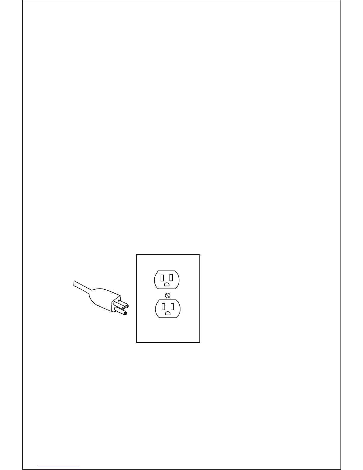
The Illustration above shows a three prong plug and outlet.
3 Prong Plug and Outlet
Only use qualified repair agents to service this power tool.
Only use qualified electrician to repair any damaged wiring.
NEVER remove the grounding prong from the power toll or extension cord.
Do not modify the plug provided. If it will not fit the outlet, have the proper outlet installed
by a qualified electrician.
Check with a qualified electrician or service personnel if the grounding instructions are
not completely understood, or if in doubt as to whether the product is properly grounded.
Repair or replace a damaged or worn cord immediately.
This product is for use on a nominal 120 V circuit and has a grounding plug similar to
the plug illustrated in Table1. Only connect the product to an outlet having the same
configuration as the plug. Do not use an adapter with this product.
8
Following this guide will greatly reduce your risk of electric shock or injury.
Grounding Instructions
Any electric powered tool that is marked Ground Required must be grounded In the event
of a malfunction or breakdown, groundingprovides a path of least resistance for electric
current to reduce the risk of electric shock.
This product is equipped with an electric cord having an equipment-grounding conductor
and a grounding plug. The plug must be plugged into a matching outlet that is properly
installed and grounded in accordance with all local codes and ordinances.
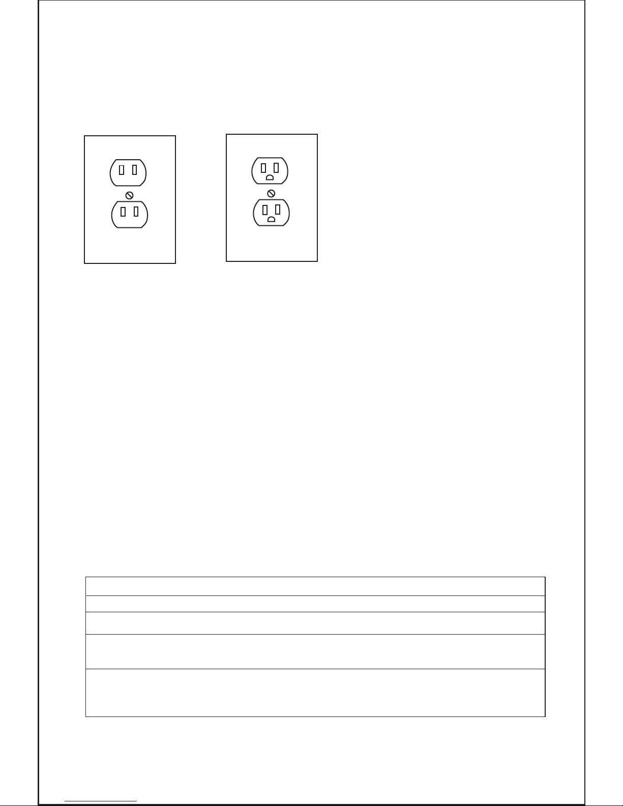
Outlets for 2-Prong Plug
Power Extension Cords
Any electric powered tool that is marked Double insulated only need a two prong
connection and will be perfectly safe to operate.
These tools do not require grounding as they are fitted with an additional insulation
system internally that complies with all relevant electrical safety standards.
Unlike the three prong tools these tools CAN be connected through outlets suitable
for two prong or three prong plugs.
The Illustration above shows the outlets that this type of tool can be connected to.
Double Insulated Power Tools
Plug and outlet, 2 prong
Any power tool marked ‘Grounding required’ MUST only be connected to a three wire
extension cord. Only double insulated tools can be connected to two wire cords.
When using any extension cord the machine will suffer a power reduction due to the
drop in voltage caused by the length of the cord. This can be partially offset by selecting
extension cords with lower gauge wire.
9
Table 1
MINIMUM GAUGE FOR CORD SETS
Total Length of Cord in Feet(Meter)
0-25 26-50 51-100 101-150
(0-7.6) (7.9-15.2) (15.5-30.5) (30.8-45.7)
Ampere Rating
AWG
0 6 18 16 16 14
18 16 14 12
16 16 14 12
14 12
Not Recommended
6 10
10 12
12 16
More Not More
Than Than

Symbols
IMPORTANT: Some of the following symbols may be used on your tool.
10
e.g. Cords marked 14 gauge can carry a higher current than cords marked 16 gauge
therefore when linking extension cords make sure each cords wire gauge matches.
Note: Outdoor extension cords used in must carry the letters “W-A” (USA) or “W”
(Canada)
Check all extension cords for damage before use.
Avoid sharp objects.
Do not position the cord where it could be subject to traffic passing over it.
V…………………………volts
A…………………………amperes
Hz……………………….hertz
~………………………..alternating current
…/m……………….revolutions per minute
.........................class II construction (double insulated)
Kg……………………….kilograms
No……………………….No load speed
Specific Safety Rules
1. Wear eye protection.
2. Keep hands out of path of saw blade. Avoid contact with any coasting blade. It can
still cause severe injury.
3. Do not operate saw without guards in place.
Check blade guard for proper closing before each use. Do not operate saw if blade
guard does not move freely and close instantly. Never clamp or tie the blade guard
into the open position.
4. Do not perform any operation freehand. The workpiece must be secured firmly
against the base and guide fence with a vise during all operations. Never use your
hand to secure the workpiece.
5. Never reach around saw blade.
6. Turn off tool and wait for saw blade to stop before moving workpiece or changing
settings.
7. Unplug tool before changing blade or servicing.
8. To reduce the risk of injury, return carriage to the full rear position after each crosscut
operation.
9. Stopper pin which locks the cutter head down is for carrying and storage purposes
only and not for any cutting operations.
10. Do not use the tool in the presence of flammable liquids or gases.
11. Check the blade carefully for cracks or damage before operation. Replace cracked
or damaged blade immediately.
Gum and wood pitch hardened on blades slows saw and increases potential for
kickback. Keep blade clean by first removing it from tool, then cleaning it with gum
and pitch remover, hot water or kerosene. Never use gasoline to clean blade.

Additional Safety rules for Laser
WARNING: This saw is equipped with a Laser light, DO NOT stare into the beam because
serious injury may occur.
11
12. While making a slide cut, KICKBACK can occur. KICKBACK occurs when the blade
binds in the workpiece during a cutting operation and the saw blade is driven back
rapidly towards the operator. Loss of control and serious personal injury can result.
If blade begins to bind during a cutting operation, do not continue to cut and release
switch immediately.
13. Use only flanges specified for this tool.
14. Be careful not to damage the arbor, flanges (especially the installing surface) or bolt.
Damage to these parts could result in blade breakage.
15. Make sure that the turn base is properly secured so it will not move during operation.
Use the holes in the base to fasten the saw to a stable work platform or bench.
NEVER use tool where operator positioning would be awkward.
16. For your safety, remove the chips, small pieces, etc. from the table top before
operation.
17. Avoid cutting nails. Inspect for and remove all nails from the workpiece before
operation.
18. Make sure the shaft lock is released before the switch is turned on.
19. Hold the handle firmly. The saw moves up or down slightly during start-up and
stopping.
20. Make sure the blade is not contacting the workpiece before the switch is turned on.
21. Before using the tool on an actual workpiece, let it run for a while. Watch for vibration
or wobbling that could indicate poor installation or a poorly balanced blade.
22. Wait until the blade attains full speed before cutting.
23. Stop operation immediately if you notice anything out of the ordinary.
24. Do not attempt to lock the trigger in the on position.
25. Stay alert. Blades are extremely dangerous
26. Use only accessories recommended in this manual. Use of improper accessories
such as abrasive wheels may cause an injury.
27. NEVER hold workpiece on right side of blade with left hand or vice versa. This is
called cross armed cutting and exposes user to risk of SERIOUS PERSONAL INJURY.
ALWAYS use vise to secure workpiece.
28. Do not abuse cord. Never pull on the cord to disconnect it from the receptacle.
Keep cord away from heat, oil, water and sharp objects.
29. Some materials contain chemicals which may be toxic. Take appropriate measures
to prevent dust inhalation and skin contact. Follow material supplier safety data.
LASER LIGHT - DO NOT STARE INTO BEAM, APERTURE, or into a reflection from
a mirror-like surface.
AVOID EXPOSURE - LASER LIGHT IS EMITTED FROM FRONT GUARD APERTURE.
CAUTION: Use of controls or adjustments, or performance of procedures other than
those specified herein may result in hazardous laser light exposure.
Assembly
WARNING: Disconnect the plug from the power source before making any assembly,
adjustments or changing accessories.
Functional Description
WARNING: Disconnect the plug from the power source before making any assembly,
adjustments or changing accessories. Such preventive safety measures reduce the risk
of starting the tool accidentally.
Clamp
To install clamp simply insert it into the provided hole on the fence on the right or left side
depending on the cut you are doing and tighten nut. (Fig.3)
Dust bag
Squeeze metal clamp and place over dust outlet and release clamp. (Fig.4)
12
Unpacking
Carefully remove the product and any accessories from the box. Make sure that all items
listed in the packing list are included. (Fig.2)
Package contents
A) Saw
B) Clamp
C) Wrench
D) Dust bag
E) Supports
F) User manual
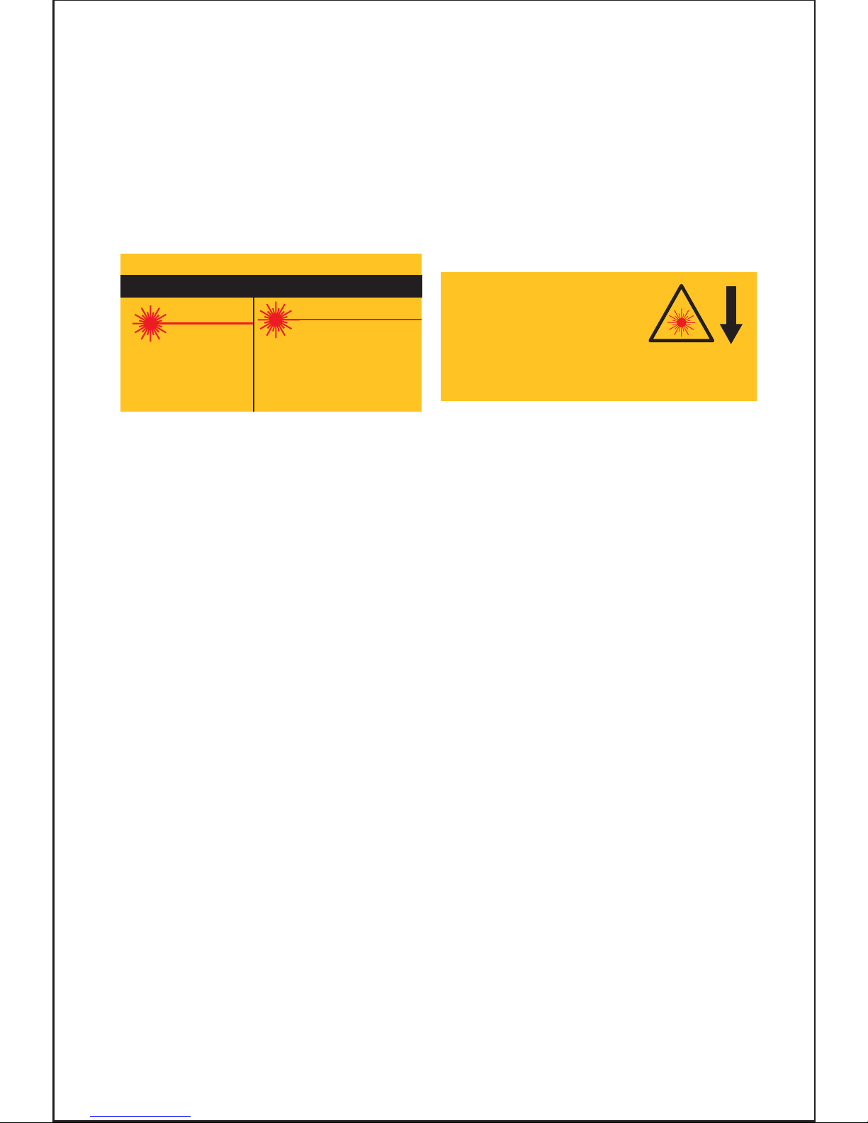
DO NOT DISASSEMBLE LASER MODULE. The laser is a CLASS II LASER PRODUCT
that can emit laser power up to 1 mw max at 635 nm, which could result in exposure
with the module disassembled. The laser unit complies with FDA21 cfr 1040.10 and
1040.11.
USE OF CONTROLS OR ADJUSTMENTS OR PERFORMANCE OF PROCEDURES OTHER
THAN THOSE SPEC IFIED HEREIN MAY RESULT IN HAZARDOUS RADIATION EXPOSURE.
WARNING: Do not attempt to repair or disassemble the laser level. If unqualified persons
attempt to repair this laser product, serious injury may result. Any repair required on
this laser product should be performed by authorized service center personnel.
CAUTION: The use of optical instruments with this product will increase eye hazard.
Wavelength: 630-670 nm
Max. power output: ǘ1 mW
Complies with
FDA21 CFR 1040.10 and 1040.11
Avoid exposure.
CAUTION
LASER RADIATION. DO
NOT STARE INTO BEAM.
ATTENTION
ClassII Laser product
Longueur d'onde: 630-670 nm
Puissance de sortie maximale: <1 mW
Conforme à
FDA21 CFR 1040.10-11.
évitez l'exposition
RAYONNEMENT LASER. NE FIXEZ
PAS LE RAYON.
Laser de catégorie II
AVOID EXPOSURE
ÉVITEZ TOUTE EXPOSITION
laser radiation is emitted
from this aperture.
Un rayonnement laser provient de cette ouverture.

Supports
Insert supports in both ends of table and secure with screw. (Fig.5)
The on/off switch has a hole to insert a pin (not provided) to avoid accidental starting.
To turn the saw on or off, squeeze and release the on/off switch. (Fig.6)
Important Note:
Transporting or moving this machine must only be done with the arm in the locked position
using the transit lock pin. (Fig.8)
When assembling your machine do not connect to the power supply until you have fully
read and understood this manual. After carrying out all checks and making any necessary
adjustments check that the machine switch is in the off position, connect to the power
supply and then switch the machine on and off quickly, this will allow you to check for
any loose blades or accessories without the machine gaining full speed. Disconnect
from the power supply before attempting any adjustments.
During manufacturing your machine is set and calibrated to cut accurately however
movement can occur during transit. If you find that your machine is not cutting accurately
you can make several small adjustments easily.
1. Disconnect the machine from the mains.
2. Lock the arm in the transit position
3. Loosen the Miter Lock Handle. (Fig.9)
4. Depress lock. (Fig.9) A
5. Align the pointer and table to 0 degrees.
6. Tighten the Miter Lock Handle.
7. Loosen the Bevel Lock Handle. (Fig.10)
8. Position the saw arm to 0 degrees with the blade 90 degrees to the table surface.
9. Tighten the Bevel Lock Handle.
Using your miter saw
Resetting the Table to 90 degrees with the Blade
On-Off Switch
Ensure that the switch is in the “OFF” position. If the plug is connected to a receptacle
while the switch is in the “ON” position, the power tool will start operating immediately
and can cause serious injury.
Turning Laser Beam ON/OFF
CAUTION: LASER RADIATION
Do not stare into beam
To turn on the laser beam, press the upper position (Fig.7) of the switch. Press the
lower position to turn off. Laser line is factory adjusted so that it is positioned within
1 mm (0.04”) from the side surface of the blade (cutting position). Make a test cut and
position material to be cut accordingly.
NOTE: When laser line is dim and almost or entirely invisible because of the direct
sunlight, relocate the work area to a place not exposed to the direct sunlight.
13

Fence to Table Adjustment
1. Disconnect the machine from the mains.
2. Lock the arm in the transit position
3. Loosen the Miter lock handle.
4. Depress lock. (Fig.9) A
5. Align the pointer and table to 0 degrees.
6. Tighten the Miter Lock handle.
7. Loosen the 4 fence screws (Pt.26)
8. Place a set square against the fence and blade (avoiding the blade teeth)
9. Adjust the fence until square.
10. Retighten the fence screws.
11. Adjust the pointer to read 0 degrees.
Blade Cutting Depth Adjustment (for use when trenching)
The blade is factory set to cut all the way through a piece of timber under normal use.
If you require a trench cut the blade can be adjusted to cut to your pre-determined depth.
Compound Miter Cuts
Basic Cross Cutting with Fixed Blade
A compound miter cut uses a Miter cut and a Bevel cut together.
The main uses for this type of cut are: picture frames, cutting moldings, roof framing and for
making boxes with sloping sides.
It is advisable to make a test cut on a piece of scrap wood before cutting into your actual
work piece.
1. Disconnect from the power supply.
2. Lift the saw Arm
3. Adjust the depth cut (Trenching) stop screw to the desired position. (Fig.13)
Always Use clamp (Fig.3) to secure the material. This clamp can be moved to either side
of the table by loosening the locking knob. Ensure this knob is retightened before using
the saw. Support long lengths using roller support stands.
4. Check depth on waste timber before commencing.
1. Pull the release knob and lift the saw arm.
2. Loosen the Miter Lock Handle (Fig.9)
3. Depress lock. (Fig.9) A
4. Move the table to the required angle.
5. Fully tighten the Miter lock handle. (If the table is not locked firmly it can result in personal
injury).Always Use clamp to secure the material. This clamp can be moved to either side
of the table by loosening the locking knob. Ensure this knob is retightened before using
the saw.Support long lengths using roller support stands.
14
10. Place a 90 deg. Set square against the table and blade (avoiding contact with the
blade teeth) rotate the blade slowly with a gloved hand, checking that it is aligned
correctly. (Fig.11)
11. Adjust the pointer to read 0 degrees. (Fig.12)
12. Retighten Bevel lock handle.
 Loading...