

Page 1
TERRATEC PRODUCER/SINE WARP 9
English Manual
Version 1.0, last revised: November 2003
Page 2

CE Declaration
We:
TerraTec Electronic GmbH, Herrenpfad 38, D-41334 Nettetal, Germany
hereby declare that the product:
TerraTec Producer SINE WARP 9,
to which this declaration refers is in compliance with the following standards or standard-
izing documents:
1. EN 55013
2. EN 55020
The following are the stipulated operating and environmental conditions for said compli-
ance:
residential, business and commercial environments and small-company environments.
This declaration is based on:
Test report(s) of the EMC testing laboratory
The information in this document is subject to change without notice and shall not be deemed as a
warranty by the seller. No warranties, express or implied, are made with regard to the quality,
suitability or accuracy of this document. The manufacturer reserves the right to change the contents
of this document and/or the associated products at any time without the provision of prior notice to
specific persons or organizations. The manufacturer shall not be held liable for damages of any
kind arising from the use, or the inability to use this product or its documentation, even if the
possibility of such damage is known. The information in this document is subject to copyright. All
rights are reserved. No part of this manual may be reproduced or transmitted in any form or for any
purpose without the express written permission of the copyright holders. Product and brand names
contained in this document are used for identification purposes only. All registered trademarks,
product designations or brand names used in this document are the registered property of their
respective owners.
®
©TerraTec
Electronic GmbH, 1994-2003. All rights reserved (12.11.03).
2 SINE WARP 9 (English)
Page 3

Contents
Important safety information........................................................................................ 4
Welcome! ....................................................................................................................... 5
Scope of delivery........................................................................................................... 5
1 Introduction ................................................................................................................ 6
1.1 Connectors and controls: ....................................................................................... 6
1.2 Properties .............................................................................................................. 8
1.3 Concept ................................................................................................................. 8
1.4 Getting started....................................................................................................... 9
2 Function.................................................................................................................... 11
2.1 VCF Modulation ................................................................................................... 11
2.2 Envelope.............................................................................................................. 12
2.3 Triggering the envelope (Trigger Source – ENV Mode) ....................................... 13
2.3.1 Trigger Source .............................................................................................. 13
2.3.2 ENV TRIGGER MODE.................................................................................. 14
2.4 VCA Modulation (VCA Mode)............................................................................... 17
2.5 LFO (Low Frequency Oscillator) .......................................................................... 18
2.5.1 LFO Wave..................................................................................................... 18
2.5.2 LFO Reset..................................................................................................... 21
2.6 Analog Trigger ..................................................................................................... 24
2.7 Output.................................................................................................................. 25
2.8 Program selection................................................................................................ 25
2.8.1 Manual program selection ............................................................................. 26
2.8.2 Program selection via MIDI ........................................................................... 26
2.9 Copying and saving programs ............................................................................. 27
2.10 MIDI send and receive channels........................................................................ 27
2.10.1 Setting the send and receive channel.......................................................... 28
2.10.2 Saving the send and receive channel.......................................................... 28
2.11 Filter mode......................................................................................................... 29
3 MIDI control ............................................................................................................. 30
4 Modulation 1 ............................................................................................................. 31
5 Appendix................................................................................................................... 32
5.1 Select 1 potentiometer calibration........................................................................ 32
5.2 Initializing programs............................................................................................. 33
Service at TerraTec Producer..................................................................................... 34
Internet, Hotline ......................................................................................................... 34
SINE WARP 9 (English) 3
Page 4

Important safety information
n
Please read all instructions before using this device.
n
Never use the device near water, i.e. next to a bathtub, sink, or drain, in a damp
basement or near a swimming pool.
n
Used in combination with an amplifier and headphones or speakers, this device can
cause sound levels that may result in lasting hearing damage. Avoid long exposure to
excessive or unpleasantly high volume levels. Consult an ear specialist immediately if
you detect a loss of hearing or a ringing in your ears.
n
Ensure adequate ventilation for the device when setting it up.
n
Do not install it near sources of heat such as radiators, ovens or similar devices.
n
Ensure that the device is connected only to a standard AC outlet.
n
Position it in such a manner that no dust, liquids or foreign objects can enter the
housing.
n
Unplug the external power supply from the AC outlet if you do not intend to use the
device for an extended period.
n
The device must be serviced by trained personnel if:
o the external power supply is damaged,
o objects or liquids have entered the device,
o the device was left in the rain,
o the device was damaged by dropping,
o the device is malfunctioning.
n
Do not attempt to repair the device yourself. Please consult a trained technician.
n
Please ensure that all analog devices are turned off before plugging them in. This will
protect you from any possible—albeit weak—electrical shocks, as well as protecting
your speakers and your hearing from sudden peaks. For digital devices, be sure to at
least lower the volume on your playback equipment.
4 SINE WARP 9 (English)
Page 5

Welcome!
We are pleased that you have chosen a TerraTec Producer rack system and would like to
congratulate you on your decision. You've purchased a sophisticated product represent-
ing the state of the art of studio technology, and we're convinced that our product will
prove extremely useful to you in the coming years and provide you with a great deal of
entertainment.
This manual describes the SINE WARP 9 MIDI analog filter. It contains everything you
need to know about the correct use of the systems, as well as a number of practical tips
that will get you started right away.
We hope you enjoy your filter and would like to suggest that you browse this hopefully
entertaining manual when you get the chance. In addition to the important information
about its technology, we have outlined a number of typical applications as well as tips and
tricks wherever appropriate. We're convinced that even experienced users will profit from
this guide.
Thanks for your attention - and here's to your creativity.
Sincerely,Your TerraTec Producer Team
Scope of delivery
Start by making sure that the contents of the package are complete.
The SINE WARP 9 MIDI analog filter must include at least:
n
19" rack filter SINE WARP 9
n
12V AC power adapter
n
Customer service card
n
Registration card with the serial number
n
BeSonic Premium Account registration card
n
This manual
Please return the enclosed registration card to us at the earliest possible opportunity or
register online at http://www.terratec.com/register.htm
and hotline services.
SINE WARP 9 (English) 5
. This is important for support
Page 6
1 Introduction
1.1 Connectors and controls:
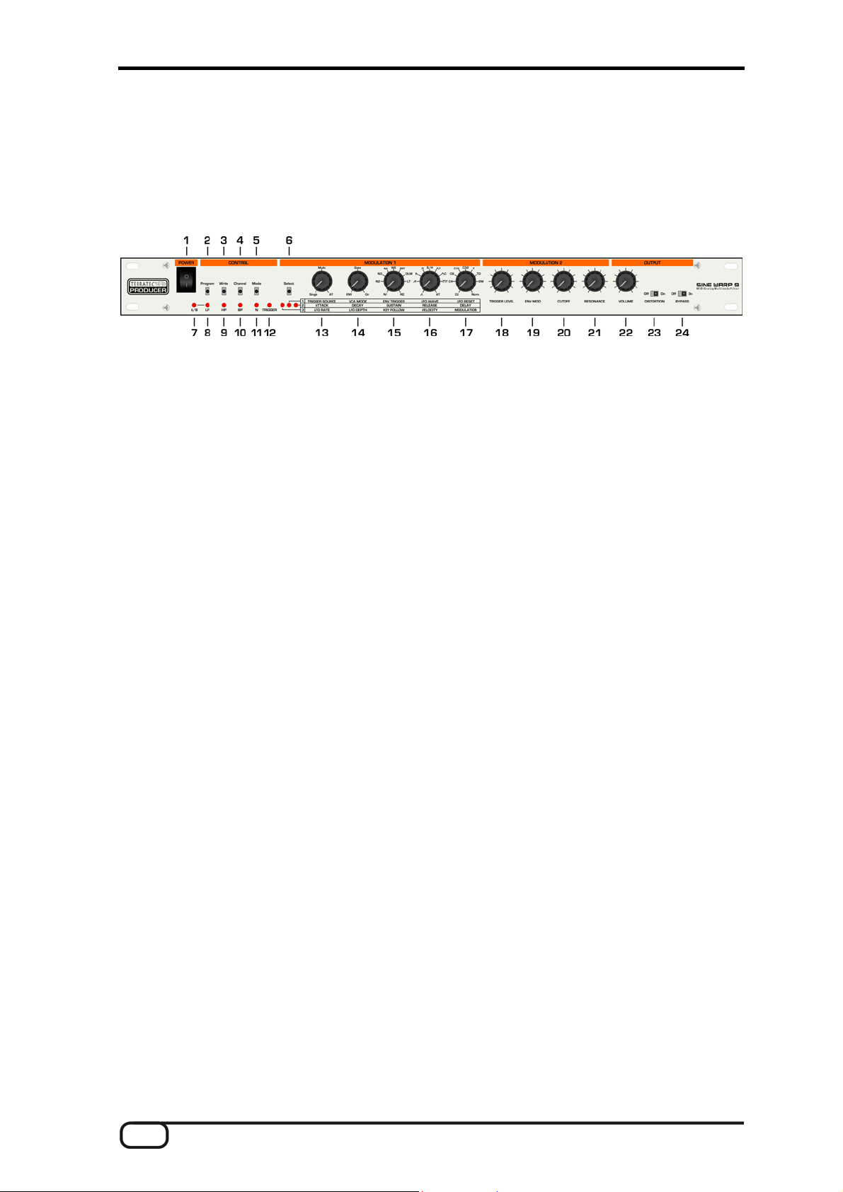
The front panel:
1. POWER: Power switch
2. Program: Program selection within the program group
3. Write: Save/copy program
4. Channel: Global MIDI send and receive channel
5. Mode: Filter type selection (monitor LED: LP/HP/BP/N)
6. Select: Selection of the active Modulation 1 parameter
7. A/B: Selection of the program group 1-16/17-32
8. LP: Low-pass filter LED
9. HP: High-pass filter LED
10. BP: Band-pass filter LED
11. N: Notch filter LED
12. TRIGGER: Monitor LED for a trigger signal
13. - 1 TRIGGER SOURCE: Selection of source (MIDI/analog) for ENV and VCA triggers
- 2 ATTACK: Envelope attack time
-3 LFO RATE: LFO speed
14. - 1 VCA MODE: Selection of VCA modulation
- 2 DECAY: Envelope decay time
- 3 LFO DEPTH: Intensity of the filter modulation (cutoff) by the LFO
15. - 1 ENV TRIGGER: Envelope trigger mode
- 2 SUSTAIN: Sustain level of envelope
- 3 KEY FOLLOW: Intensity of the filter modulation (cutoff) by MIDI notes
16. - 1 LFO WAVE: Selection of the LFO waveform
- 2 RELEASE: Release time of the envelope
- 3 VELOCITY: Intensity of the filter modulation (cutoff) by MIDI velocity
6 SINE WARP 9 (English)
Page 7
17. - 1 LFO RESET: Selection of the LFO reset mode
- 2 DELAY: Envelope triggering delay time
- 3 MODULATION: Intensity of the filter modulation (cutoff) by the modulation wheel
18. TRIGGER LEVEL: Trigger threshold for analog triggering
19. ENV MOD: Intensity of the filter modulation (cutoff) by the envelope
20. CUTOFF: Manual adjustment of the cutoff frequency
21. RESONANCE: Manual adjustment of the filter resonance
22. VOLUME: Output volume
23. DISTORTION: Distortion effect on/off switch
24. BYPASS: Selector for original/filtered signal at output
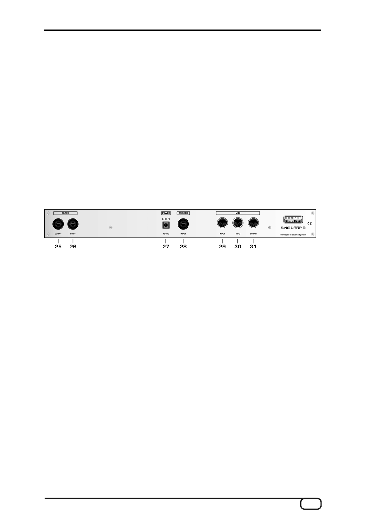
The rear panel:
25. FILTER OUTPUT: Output socket (1/4" mono jack)
26. FILTER INPUT: Input socket (1/4" mono jack)
27. POWER 12 VAC: AC power
28. TRIGGER INPUT: Input for analog triggering. If this socket is not used, the
FILTER INPUT signal will serve as the analog trigger signal.
29. MIDI INPUT: The data received here is used to switch programs, trigger
the envelope and VCA and control the filter parameters.
30. MIDI THRU: MIDI feed-through socket
31. MIDI OUTPUT: Controller data output of the edited parameters
SINE WARP 9 (English) 7
Page 8
1.2 Properties
n
MIDI-controllable 12 dB filter with resonance
n
Filter types: Choice of low-pass, high-pass, bandpass and notch filter
n
Volume modulation through VCA
n
Filter modulations: LFO, envelope and MIDI combinable
n
Control positions sent and received via MIDI
n
32 program memory slots
n
Analog trigger input
n
Switchable distortion effect
n
Connections: Filter In/Out, Trigger In, MIDI In/Out/Thru,
n
external power supply
n
1 HE, 19 inches
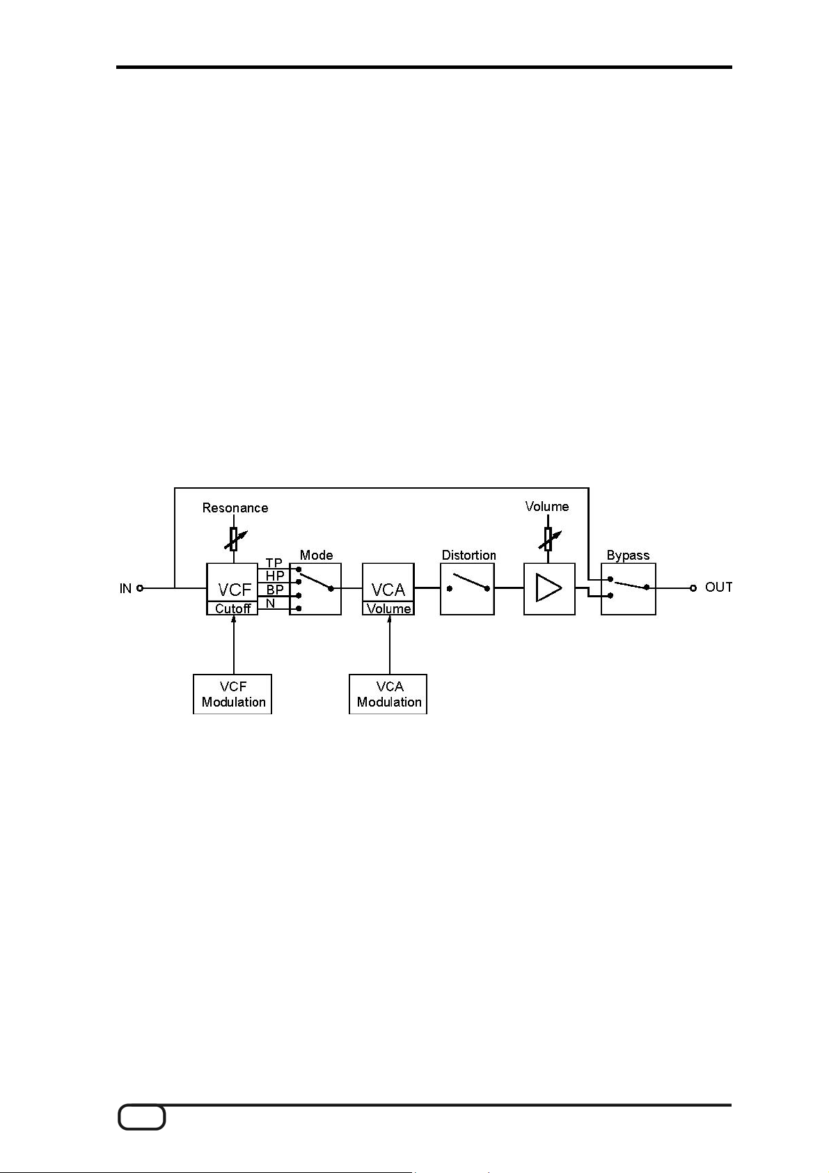
1.3 Concept
The input signal initially passes through an analog, voltage-controlled 12 dB filter with a
variable resonance and cutoff frequency. The Function mode is used to select the VCF
filter characteristic (low-pass, bandpass or notch). The dynamics of the filtered signal are
then influenced by a voltage-controlled amplifier (VCA). The output features a volume
control, a switchable distortion effect and a bypass switch. The modulation of the VCF is
described in 2.1 and the VCA in 2.4.
8 SINE WARP 9 (English)
Page 9

1.4 Getting started
n
Connect the included power adapter to the 12V AC socket on the rear panel of the
SINE WARP 9. Switch the device on. The programs have been preconfigured with the
following values:
o MIDI channel: 1
o Filter Mode: Low-pass
o Trigger Source: AT (analog trigger)
o ENV Trigger Mode: N1 (trigger envelope at beginning of trigger)
o VCA Mode: On (VCA permanently on)
o LFO Wave: Triangle
o LFO Reset: Norm (no reset)
o LFO Depth: 0
o MIDI Modulation: Velocity, key follow, modulation wheel: OFF
n
Connect an audio signal source to the FILTER INPUT socket and connect the output
of the SINE WARP 9 (FILTER OUTPUT socket) to an amplifier or mixer.
n
Operation without MIDI:
Set the resonance and cutoff filter parameters and the filter modes (select with the
mode button) according to your wishes. By default the envelope is triggered by the
filter input signal. Set the trigger level to ensure that triggering occurs (the Trigger
LED lights up).
The cutoff frequency is modulated by the envelope. Set the intensity of this modulation with the ENV MOD control. The envelope characteristic can be set using the envelope parameters Attack, Decay, Sustain, Release and Delay (Select on 2). In addition, the cutoff frequency can be modulated using the LFO. Change the LFO Rate and
LFO Depth parameters (Select on 3) for this purpose and select the waveforms using
the LFO Wave control (Select on 1).
Set the VCA mode (Select on 1). In the Gate position, the VCA is active at constant
volume when the trigger is active, in the ENV position the VCA is modulated by the
envelope.
n
Operation with MIDI:
Select Single mode as the trigger source (Select on 1). Next, trigger the envelope by
sending Note On/Off messages to MIDI In (channel 1). The Trigger LED must flash on
the Note On message.
The cutoff frequency can be modulated additionally with Velocity, Key Follow or the
modulation wheel (Channel 1, Select on 3). Modulation is disabled in the middle position (when the Select LED flashes).
SINE WARP 9 (English) 9
Page 10

n
Controlling filters via MIDI:
Connect a sequencer to the MIDI OUTPUT, start the sequencer in recording mode
and adjust the Cutoff control, for example. The SINE WARP 9 will send controller data
(channel 1) that will be recorded by the sequencer. When the sequencer sends the
recorded controller data back to the WARP 9, the cutoff frequency will change to
match the controller adjustment during recording.
n
Saving:
To save the current settings, press the Write button. Press the Program button to
select the program number under which you would like to save the settings. Each
program number is indicated by a different state of the LP, HP, BP and N LEDs. Press
the write button again to save the program. To cancel: press the Channel button, for
example.
n
Other functions:
In principle, you are now acquainted with the essential functions of the SINE WARP 9.
Unusual modulations can be achieved with a variety of envelope mode settings (ENV
Mode control), LFO waveforms (LFO Wave control, Select on 1) and LFO resets (LFO
Reset control, Select on 1).
n
For more information, read the manual thoroughly.
10 SINE WARP 9 (English)
Page 11
2 Function
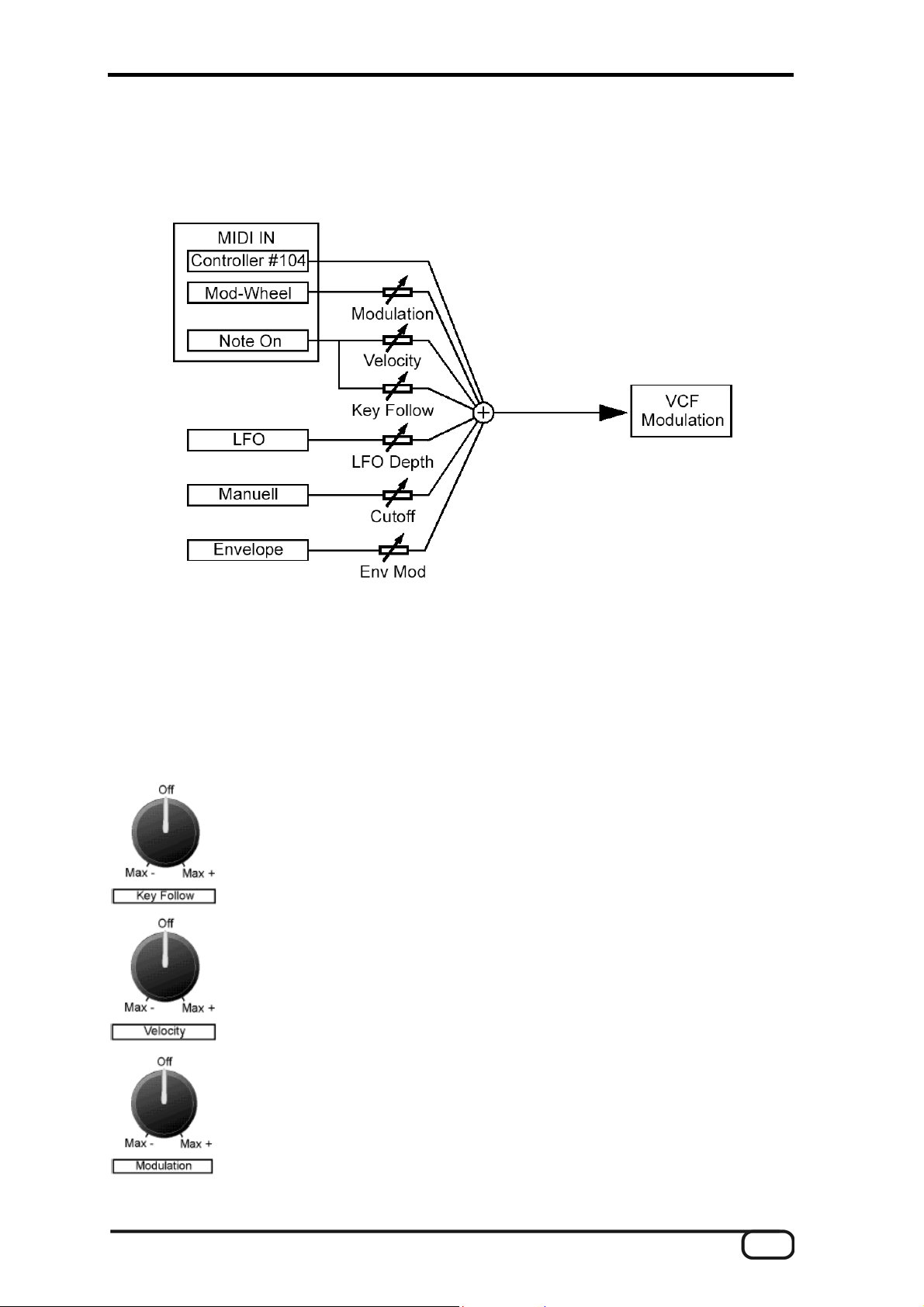
2.1 VCF Modulation
A variety of modulation sources that can be combined as needed are available for the
modulation of the cutoff frequency.
n MIDI
Controller (#104), modulation wheel, velocity and note data of the received Note On
messages are processed. The intensity with which this data affects the cutoff fre-
quency can be adjusted with the Velocity, Key Follow and Modulation controls:
Off:
Off...Max+:
Max-...Off:
Off:
Off...Max+
Max-...Off:
Note data is not processed
Notes higher than C3 increase, notes lower than C3
decrease the cutoff frequency
Notes lower than C3 increase, notes higher than C3
decrease the cutoff frequency
Velocity data is not processed
Increasing velocity values raise the cutoff frequency
Increasing velocity values lower the cutoff frequency
Off:
Off...Max+:
Max-...Off:
SINE WARP 9 (English) 11
Modulation wheel data is not processed
Increasing modulation wheel values raise the cutoff
frequency
Increasing modulation wheel values lower the cutoff
frequency
Page 12

n
LFO
The LFO depth control adjusts the intensity of the LFO modulation.
n
Manual
Manual adjustment of the cutoff frequency with the Cutoff control
n
Envelope
Modulation of the cutoff frequency by the envelope of the SINE WARP 9. The ENV
MOD control adjusts the modulation depth.
2.2 Envelope
The Warp 9 features an ADSR envelope with an adjustable delay. The following diagram
shows the temporal progression of the envelope voltage when triggering the envelope.
The envelope parameters can be set with the appropriate controls under MODULATION 1
(Select on 2):
n
Delay: 0 - 1 second
n
Attack: 1 millisecond - 10 seconds
n
Decay: 1 millisecond - 10 seconds
n
Sustain: 0 - 100%
n
Release: 1 millisecond - 10 seconds
12 SINE WARP 9 (English)
Page 13

2.3 Triggering the envelope (Trigger Source – ENV Mode)
The following diagram illustrates the functional principle of the envelope circuit:
The envelope is triggered either by an analog signal applied to the FILTER INPUT or
TRIGGER INPUT, or via MIDI using Note On/Off messages. Select one of the possible
trigger types with Trigger Source. The original trigger signals (to Trigger Source) do not
trigger the envelope directly, but are influenced by the ENV MODE parameter. For
example, trigger signals are filtered out when the LFO drops below a specific value or
only every second trigger signal is allowed to pass.
2.3.1 Trigger Source
n
Single
A trigger pulse is activated by each Note On message on the currently selected re-
ceive channel. The trigger pulse is ended by a Note Off message with the same note
number (start of the release phase).
n
Multi
A trigger pulse is only activated by a Note On message if no other notes are active (all
previously received notes were ended by specific Note Off messages or an All Note
Off message. The triggering ends when all received notes (Note On messages) have
been switched off (equivalent of an All Note Off message).
n
AT
Trigger signals are created by a connected audio signal.
SINE WARP 9 (English) 13
Page 14

2.3.2 ENV TRIGGER MODE
n n N1
Each trigger signal after the trigger source triggers the envelope.
N2,N3,N4,N5
The envelope is triggered only after every other (N2), every third (N3), every fourth
(N4) or fifth (N5) trigger signal. All trigger signals in between are ignored.
Example: Trigger Source: Single, ENV MODE: N3
n RPT
During an active trigger signal, the envelope will be triggered again every time the
envelope voltage drops to the sustain level (end of the decay phase). This occurs with
increasing frequency the lower the delay, attack and decay times are. The release
phase does not begin until the end of the trigger. Very short delay, attack and decay
times result in a very high repeat frequency, resulting in an effect similar to a ring
modulator.
Example: Delay, Attack at minimum, Sustain 50%
14 SINE WARP 9 (English)
Page 15

n DLM (Delay-LFO Modulation)
In this mode, each trigger signal after Trigg Source triggers the envelope, but the
decay time changes depending on the current LFO value. The effect on the decay
times depends on the position of the Decay control. Positions near the minimum and
maximum values are especially effective.
Range 1:
Increasing (decreasing) LFO values cause the decay to
increase (decrease). The closer the control is to the MIN
position, the shorter the overall decay time.
Range 2:
Depending on the current LFO value, the device switches
between maximum (high LFO value) and minimum decay time
(low LFO value). The closer the control is to the MAX position,
the more prevalent minimal decay times will be.
Example: Range 1, triangle LFO, Delay, Attack, Sustain and Release minimum
SINE WARP 9 (English) 15
Page 16

n LT (LFO trigger)
A trigger signal will only activate the envelope if the current LFO value is greater than
50%.
Example: triangle LFO, Delay, Attack, Sustain and Release minimum
n RD (Retrigger Delay)
At the beginning of the trigger activation, the envelope is initially triggered without
delay (start of the attack phase). After the delay time from the start of the trigger has
elapsed, the envelope is triggered again, provided the trigger is still active. Unlike RPT
mode, the envelope will not be triggered further. The envelope will only be triggered
once if the trigger pulse is shorter than the delay time.
16 SINE WARP 9 (English)
Page 17

2.4 VCA Modulation (VCA Mode)
The following diagram shows the various VCA modulation options:
n
ENV
The envelope voltage controls the volume of the VCA. The Trigger Source and ENV
Mode parameters must also be taken into consideration here.
n
Gate
An active trigger signal after Trigger Source activates the VCA; if no trigger signal has
been applied, the VCA is muted.
n
ON
This means that the VCA is permanently enabled.
The ENV/Gate/On VCA control signals can be influenced with controller 113 to increase
or decrease the volume of the VCA. Valid controller values range from 0 (VCA mute) to
127 (maximum VCA volume). Please note that the VCA is always mute in Gate or ENV
mode (if no trigger signal has been applied or the envelope has not been triggered). Only
an active gate signal or a triggered envelope can be influenced by the controller.
SINE WARP 9 (English) 17
Page 18

2.5 LFO (Low Frequency Oscillator)
The LFO modulates the cutoff frequency. It has the parameters LFO Rate, LFO Depth,
LFO Wave and LFO Reset which can be adjusted using the appropriate controls under
Modulation 1.
n
LFO Rate
Speed of the LFO with an adjustable frequency from 0.01 Hz to 10 Hz
n
LFO Depth
Intensity with which the LFO modulates the cutoff frequency (0 to maximum)
n
LFO Wave
Selection of possible waveforms. In addition to "traditional" waveforms such as square
wave, triangle, sawtooth, inverted sawtooth and random, waveforms are also available
that can be manipulated by incoming trigger signals. These can be used to achieve
rhythmic modulations.
n
LFO Reset
One strength of the LFO is its reset options. In this case this means restarting the
LFO, starting at the lowest value. Resets can be triggered via the MIDI clock, Note On
messages or Control Change messages.
The following is a detailed description of the LFO Wave and LFO Reset parameters.
2.5.1 LFO Wave
This section covers the various waveforms of the LFO. The following explanations apply
in the event that the LFO is not reset (LFO Reset control in Norm position). The triggered
waveforms process the trigger signals selected with Trigger Source.
n
The waveforms correspond to the illustrations below. S/H is a waveform in which the
LFO generates random values.
Triangle
Sawtooth
Inverted sawtooth
Square wave
S/H Random
18 SINE WARP 9 (English)
Page 19

n
Generates a staircase voltage in which the triangle LFO is sampled by incoming trig-
ger signals (Note ON or analog). With each trigger pulse, the LFO takes over the
momentary triangle LFO value and holds it until the next trigger pulse is received. The
random character of the staircase voltage increases as the trigger pulses become
less regular and the LFO rate increases.
n
This waveform is a combination of triangle LFO and a staircase voltage. If no trigger
pulse is received, the LFO generates a normal triangle signal. With each trigger pulse,
the LFO value jumps upward (in the case of an ascending triangle flank) or downward
(descending flank). The height of the jump increases with the LFO rate.
SINE WARP 9 (English) 19
Page 20

n
Corresponds to the
waveform with the difference that the LFO value is alter-
nately sampled from a normal triangle LFO and an inverted triangle LFO.
n AT
The LFO generates a constant value that increases with each trigger pulse. This in-
crease depends on the LFO rate, with a high LFO rate resulting in high jumps. The
LFO once again starts at the minimum once a maximum value has been reached.
20 SINE WARP 9 (English)
Page 21

2.5.2 LFO Reset
n C2, C4, C8, C16, C32
The LFO Reset is triggered by the MIDI clock and after a specified number of quarter
notes. Resets can be triggered after 2 (C2), 4 (C4), 8 (C8), 16 (C16) and 32 (C32)
quarter notes. A reset affects the various waveforms differently:
o
The LFO starts at the reset and stops after a period. If the period is not yet
complete, the LFO will restart when reset. The duration of a period de-
pends on the LFO rate. A suitable LFO rate must be selected to ensure
that the period is positioned exactly between two reset signals, with the
LFO synchronized with the MIDI clock.
Example: Triangle
o S/H
The LFO generates a new random value with each reset. The LFO Rate
control does not have any effect in this case.
o
The staircase voltage as described in 2.5.1 is reset to its minimum value
with each reset. If one period of the triangle signal from which the staircase
voltage was generated has elapsed, the LFO will remain at its minimum
value.
o
The staircase voltage as described in 2.5.1 is reset to its minimum value
with each reset. If one period of the triangle signal from which the staircase
voltage was generated has elapsed, the LFO will remain at its minimum
value.
o AT
The staircase voltage as described in 2.5.1 is reset to its minimum value
with each reset.
SINE WARP 9 (English) 21
Page 22

n T
The LFO Reset is activated by trigger signals (selection: Trigger Source). A reset
affects the various waveforms differently:
o
The LFO runs continuously and starts at its minimum value when reset.
Example: Triangle
n TD
o S/H
The LFO generates a new random value with each reset. The LFO Rate
control does not have any effect in this case.
o Other waveforms
The LFO does not have any effect in this case.
o
The LFO runs continuously and starts at its minimum value when reset.
The reset is activated at the end of the trigger (e.g. Trigger Source = MIDI:
Note Off).
Example: Triangle
o S/H
The LFO generates a new random value at each start and end of a trigger.
The LFO Rate control does not have any effect in this case.
22 SINE WARP 9 (English)
Page 23

o AT
The staircase voltages as described in 2.5.1 change their values both at
the start and end of a trigger.
Example: AT
n EM
The same waveforms result as described in 2.5.1 (LFO Reset: Norm). The LFO is not
reset, but the LFO intensity will be influenced by both the LFO Depth control and the
envelope voltage. For example, the LFO intensity increases in the attack phase and
drops to the sustain level after the decay phase. The LFO intensity will be 0 at the end
of the release phase.
Example; triangle LFO
SINE WARP 9 (English) 23
Page 24

n Norm
In Norm mode, the same waveforms result as described in 2.5.1. The LFO runs con-
tinuously and is not reset.
MIDI Reset
In Norm mode an LFO reset can also be triggered by a Control Change message
(#114, any data value). In this case, the LFO behaves in the same way as in modes
C2 - C32. For example, the LFO is reset to its minimum value and only one period is
generated when using triangle, sawtooth, inverted sawtooth and square-wave wave-
forms. To return to the normal mode (LFO continuously on), set the LFO Reset control
to a different mode and then back to the Norm position.
2.6 Analog Trigger
Either an audio signal applied to the TRIGGER INPUT socket or the filter input signal
(TRIGGER INPUT socket open) can be used as an analog trigger signal to activate the
envelope or generate the VCA gate voltage. The volume at which the analog trigger takes
effect depends on the selected trigger level.
24 SINE WARP 9 (English)
Page 25

2.7 Output
n
Volume
Controls the output volume of the Warp 9. A high volume or an excessive input level
can distort the signal. In this case, please lower the volume.
n
Distortion
The distortion effect is disabled when the switch is in the Off position. To enable the
distortion at the output of the Warp 9, switch it on here. The strength of the effect
depends on the volume setting.
n
Bypass
Switches between the filtered and original signal.
2.8 Program selection
The SINE WARP 9 features 32 program memory slots organized in 2 groups (A/B) of 16
programs each. The following data is stored in a program:
n
Filter mode
n
All Modulation 1 parameters
n
ENV MOD, Cutoff and Resonance
The output settings (Volume, Distortion and Bypass) as well as the trigger levels cannot
be stored. The MIDI send and receive channel is global and is therefore shared by all 32
programs. It can be stored together with the active program number that is loaded
automatically when switching the device on.
SINE WARP 9 (English) 25
Page 26

2.8.1 Manual program selection
1. Press the Program button briefly until the Program LED starts to flash.
2. Press the Program button repeatedly until the desired program has been selected.
Depending on the currently active program group A/B, either programs 1-16 (A active,
LED A/B not lit) or 17-32 (B active, LED A/B lit) will be available for selection. The 4
LP/HP/BP/N LEDs serve as the display of one of the 16 program numbers within the
active program group.
3. Selecting the program group A/B. Press and hold the Program button (approx. 1
second) to switch program groups. The following chart shows the status of the LEDs
depending on the selected program number.
A/B LP HP BP N Prog A/B LP HP BP N Prog
¡ ¡ ¡ ¡ ¡
¡ l ¡ ¡ ¡
¡ ¡ l ¡ ¡
¡ l l ¡ ¡
¡ ¡ ¡ l ¡
¡ l ¡ l ¡
¡ ¡ l l ¡
¡ l l l ¡
¡ ¡ ¡ ¡ l
¡ l ¡ ¡ l
¡ ¡ l ¡ l
¡ l l ¡ l
¡ ¡ ¡ l l
¡ l ¡ l l
¡ ¡ l l l
1
2
3
4
5
6
7
8
9
10
11
12
13
14
15
l ¡ ¡ ¡ ¡
l l ¡ ¡ ¡
l ¡ l ¡ ¡
l l l ¡ ¡
l ¡ ¡ l l
l l ¡ l ¡
l ¡ l l ¡
l l l l ¡
l ¡ ¡ ¡ l
l l ¡ ¡ l
l ¡ l ¡ l
l l l ¡ L
l ¡ ¡ l l
l l ¡ l l
l ¡ l l l
17
18
19
20
21
22
23
24
25
26
27
28
29
30
31
¡ l l l l
16
l l l l l
32
2.8.2 Program selection via MIDI
Programs can be selected via MIDI using Program Change messages containing
program numbers (1-32). Please note that Programm Change messages will only be
accepted if they are sent on the send and receive channel of the SINE WARP 9.
26 SINE WARP 9 (English)
Page 27

2.9 Copying and saving programs
Individual parameters of a program that have been changed will be lost when choosing a
new program or switching the device off. Parameter changes to a program must be saved
if you intend to keep them.
n
Saving a program
o Press the Write button briefly until the Write LED is lit.
o Press the Write button again. All parameter changes to the currently se-
lected program will be saved. After the program has been saved, the program selection function will be activated automatically.
n
Copying a program
o Press the Program button briefly to select the program to copy.
o Press the Write button briefly until the Write LED is flashing.
o Press the Program button briefly (the Write LED will continue to flash) to
select the target program within the current program group, or hold the
Program button to select a target program group (A/B). The target program
will be displayed as described in 2.8.
o Press the Write button to copy the program. After the program has been
copied, the program selection function will be activated automatically.
Note: Press the Channel or Mode button to cancel the copy operation.
2.10 MIDI send and receive channels
The SINE WARP 9 sends and receives the following channel-dependent MIDI data:
n
Program Change messages for program selection (receive)
n
Note On/Note Off for envelope triggering (receive)
n
Control Change messages for parameter changes (send and receive)
A shared send and receive channel can be selected at the SINE WARP 9 for sending and
receiving data.
SINE WARP 9 (English) 27
Page 28

2.10.1 Setting the send and receive channel
n n Press the Channel button briefly until the Channel LED starts to flash.
Press the Channel repeatedly to increment the MIDI channel upward by 1 (selection:
1-16). The 4 LP/HP/BP/N LEDs serve to display the MIDI channel.
LP HP BP N Channel
¡ ¡ ¡ ¡
l ¡ ¡ ¡
¡ l ¡ ¡
l l ¡ ¡
¡ ¡ l ¡
l ¡ l ¡
¡ l l ¡
l l l ¡
¡ ¡ ¡ l
l ¡ ¡ l
¡ l ¡ l
l l ¡ l
¡ ¡ l l
l ¡ l l
¡ l l l
l l l l
1
2
3
4
5
6
7
8
9
10
11
12
13
14
15
16
2.10.2 Saving the send and receive channel
The channel setting must be saved to retain it from one session to another. This will also
save the active program number, i.e. the program number that will be loaded automati-
cally when switching the device on.
n n Press the Write button briefly until the Write LED is lit. The settings have now been
saved.
Press the Program, Channel or Mode button to exit the Write function.
28 SINE WARP 9 (English)
Page 29

2.11 Filter mode
The Filter of the SINE WARP 9 works in the following modes:
n
Low-pass (LP)
n
High-pass (HP)
n
Band-pass (BP)
n
Notch filter (N)
The frequency responses of the individual filter types are depicted below. The low-pass
filter lets all frequencies below the cutoff frequency pass and suppresses higher frequen-
cies. The high-pass filter lets all frequencies above the cutoff frequency pass and
suppresses lower frequencies. The bandpass filter only lets signals around the cutoff
frequency pass. The notch filter suppresses the frequency range around the cutoff
frequency. The frequency response around the cutoff frequency varies depending on the
resonance (dotted line corresponds to the filter with high resonance).
Selecting the filter mode
n n Press the Mode button briefly until the Mode LED starts to flash.
Press the Mode button until the desired filter mode is displayed.
LP HP BP N Mode
l ¡ ¡ ¡
¡ L ¡ ¡
¡ ¡ L ¡
¡ ¡ ¡ L
Low-pass
High-pass
Band-pass
Notch
SINE WARP 9 (English) 29
Page 30

3 MIDI control
The SINE WARP 9 sends and receives the following MIDI data:
n
Program Changes (1-32, reception only on the active receive channel)
n
Midi Clock (for LFO reset)
n
Note On/Off (for ENV/VCA triggers, reception only on the active receive channel)
n
Control Changes (sending and reception only on the active receive channel)
If a parameter is modified by changing one of the controls, the SINE WARP 9 will send an
appropriate control-change message to the MIDI OUT which can then be recorded by a
MIDI sequencer. If these controller messages are sent back to the SINE WARP 9, the
parameter will be set according to the value. The following table provides an overview of
the parameters and the associated controller messages sent and received via MIDI.
Parameter Controller number Controller values
ENV mode 103 0 – 127
Cutoff 104 0 – 127
Resonance 105 0 – 127
Attack 106 0 – 127
Decay 107 0 – 127
Sustain 108 0 – 127
Release 109 0 – 127
Delay 110 0 – 127
LFO rate 111 0 – 127
LFO depth 112 0 – 127
Controller value 0 corresponds to the control knob in the minimum position.
Controller value 127 corresponds to the control knob in the maximum position.
n Controller Changes (reception only on the active receive channel)
Parameter Controller number Controller values
VCA control 113 0 – 127
LFO reset: 104 0 – 127
Filter mode 105 0 – 127
Modulation wheel 106 0 – 127
30 SINE WARP 9 (English)
Page 31

4 Modulation 1
This section is organized in the 3 parameter groups Select 1, Select 2 and Select 3. Use
the Select button to select one of the 3 parameter groups. You can then edit the individual
parameters within the group with the above control knobs.
When switching to a different parameter group while editing parameters, the positions of
the control knobs will still show the values of the previous group, even if the parameters of
the current group have completely different values. The parameter will not take on the
value shown by the control knob until you move the knob. An example: suppose you have
chosen Select 2 and set the Attack value to minimum. Next, you choose Select 3 and set
the LFO Rate to maximum. If you go back to Select 2, the control knob will be set to
maximum, but the Attack value will still be at minimum. If you now move the control knob,
the Attack value will change to the current position of the control knob.
The control knobs of the 3 parameter groups have different value ranges. The values on
the labels of the front panel of the Warp 9 apply to the Select 1 parameters.
SINE WARP 9 (English) 31
Page 32

5 Appendix
5.1 Select 1 potentiometer calibration
If the valid positions of the Select 1 parameters (a value is recognized as valid when the
Select 1 LED is not flashing) do not correspond to the control knob increments on the
front panel of the Warp 9 (after a control knob has been replaced, for example) you may
set and permanently store the positions recognized as valid. Proceed as follows:
n
When switching the device on, press and hold the Program and Write buttons at the
same time. The Select and Trigger LEDs must remain lit. The LP, HP and BP LEDs
are not lit.
n
The various valid control knob positions can be calibrated without the left and right
values. When calibrating, set all 5 control knobs to one of 7 possible positions. These
7 possible positions are shown below using the LFO Reset control as an example.
n
Turn all 5 control knobs below Modulation 1 to position 1. All controls should be
positioned so that they point exactly at the second value (LFO Reset knob on C4, LFO
Wave on Sawtooth, ENV Mode on N2). The Trigger Source and VCA Mode controls
should also be in these positions, even though they do not have values at this point,
n
Save this position by pressing the Write button.
n
To set the next position (2), press the Program button briefly. The LP, HP and BP
LEDs will now light as shown below under Position 2. Next, set all 5 controls in Position 2 so that they point exactly at the third value (LFO Reset: C8, LFO Wave: , ENV
mode: N3). The ENV Mode and VCA Mode controls should also be in this position.
n
Save this position by pressing the Write button.
n
Repeat this process for the remaining positions 3 to 7, i.e. press the Program button
first to select the next position in accordance with the LEDs, set all knobs to the position and save the control positions with the Write button.
n n After saving Position 7, press the Channel button to exit the calibration mode.
To check whether the calibration has been performed correctly, choose Select 1 and
set the controls to the position of the various values. The Select LED must remain lit
(value recognized). The value is invalid if the LED flashes between two values.
32 SINE WARP 9 (English)
Page 33

5.2 Initializing programs
All 32 programs can be saved with the following preset values:
MIDI channel: 1
Filter mode: Low-pass (LP)
Trigger source: AT (analog trigger)
ENV mode N1 (trigger envelope at beginning of trigger)
VCA mode: On (VCA permanently on)
LFO wave:
LFO reset: Norm (no reset)
LFO depth: 0
MIDI mdulation: Velocity, Key Follow, Modulation Wheel: OFF
When switching the device on, press and hold the Channel and Mode buttons at the
same time. The 32 programs will be initialized one at a time. The process is complete
when the Prog LED starts to flash. The Warp 9 will then be in normal operating mode.
(triangle)
SINE WARP 9 (English) 33
Page 34

Service at TerraTec Producer
Sometimes, no matter how good the weather is, things do not always work as they
should. Problems can arise in the best studio systems. If this happens to you, the
TerraTec Producer team is happy to offer its service and support.
Internet, Hotline
If you have a tough problem—where you cannot solve the problem yourself, the support
in this manual doesn't resolve the problem, and your dealer can't fix it either—please
contact us directly.
If possible, try our Internet support system first: under http://www.terratec.com/
always find current answers to frequently asked questions (FAQ).
If these options do not provide the necessary help, please contact our phone hotline. You
can also reach us online.
To do so, visit us at http://supporten.terratec.net/
In either case, please have the following information handy:
n n your registration number
this documentation.
In addition, it would be helpful to our technicians if you are at your device during the
phone call to directly carry out tips and tricks. Please do not forget to write down the
name of the respective support technician if you contact our Support Team. You will need
this name if a defect is present and your device needs to be mailed to us.
.
you will
34 SINE WARP 9 (English)
 Loading...