

Page 1

NOTICE CALIFORNIA
7300 • 7400 • 7500 • 7600 Models August 2010
WORKSTAR
Be advised that this motor vehicle may be equipped with
computer / recording devices. Their function is to allow an
authorized individual to download data or information
relating to the operation or performance of this vehicle.
The stored data or information may be neither downloaded
nor retrieved except by the vehicle’s registered owner, or, in
the alternative, by another individual or entity authorized by
the registered owner, such as an International Dealer, who
may need this data or information to properly service or
diagnose this vehicle for repair or following an accident.
Any access to this information without the owner’s consent
may be in violation of law and may subject that person or
entity to criminal penalties.
The information, specifications, and illustrations contained in this manual are based on data that
was current at the time of publication. International reserves the right to make changes and/or
improvements at any time without notification or liability, or without applying those changes or
improvements to vehicles previously manufactured.
Make sure your use of this completed vehicle conforms to all federal, state
and local requirements and regulations imposed on owners and operators.
Important
Proposition 65 Warning
Diesel engine exhaust and some of its
constituents are known to the State of California
to cause cancer, birth defects, and other
reproductive harm.
Battery posts, terminals and related accessories
contain lead and lead compounds, chemicals
known to the State of California to cause cancer
and reproductive harm.
Wash hands after handling.
®
Series 3879634R1
Printed in the United States of America
© 2010 Navistar, Inc. All Rights Reserved
Page 2
Operator’s Manual – WORKSTAR® Series
IMPORTANT
IT IS IMPORTANT THAT THE VEHICLE IDENTIFICATION NUMBER (VIN), AND COMPONENT FEATURE CODE AND SERIAL
NUMBERS BE RECORDED. THESE NUMBERS ARE REQUIRED TO OBTAIN INFORMATION PERTINENT TO THIS VEHICLE.
VIN (VEHICLE IDENTIFICATION
NUMBER) LOCATION
LoneStar®, 9000i, ProStar®+, TranStar®,
®
PayStar
TerraStar™ Series: Located left door
opening, rear post
, WorkStar®, DuraStar®, and
COMPONENT IDENTIFICATION
NUMBERS
Component Feature Codes appear on the
vehicle line set ticket.
Component serial numbers appear on the
components.
Feature Code: Serial Number:
FRONT AXLE
REAR AXLE
TRANSFER CASE
TRANSMISSION
ENGINE
ENGINE SERIAL NUMBER LOCATION
MAXXFORCE®: Stamped on pad – right side
of the crankcase, below cylinder head
WORLD HEADQUARTERS
Navistar, Inc.
4201 Winfield Road
Warrenville, Illinois 60555 USA
INTERNATIONAL INTERNET SITE
internationaltrucks.com
SALES REGIONS
MIDWEST
Navistar, Inc.
4201 Winfield Road
PO Box 1488
Warrenville, Illinois 60555
630-753-5900
NORTHEAST
Navistar, Inc.
Cherry Tree Corporate Center
535 Route 38 East, Suite 300
Cherry Hill, New Jersey 08002
856-486-2300
SOUTHEAST
Navistar, Inc.
2400 Commerce Avenue
Building 1100, Suite 100
Duluth, Georgia 30096
678-584-2700
SOUTHWEST
Navistar, Inc.
2595 Dallas Parkway, Suite 203
Frisco, Texas 75034
972-377-1200
WEST
Navistar, Inc.
3017 Douglas Boulevard, Suite 300
Roseville, California 95661
916-774-7526
CANADA
Navistar Canada, Inc.
5500 North Service Road – 4th Floor
Box 5337
Burlington, Ontario L7L 5H7
905-332-3323
MEXICO
Navistar Mexico SA DE CV
Ejército Nacional 904 – 8° Piso
Col, Palmas Polanco 11510 Mexico D.F.
525-262-6666
BRAZIL
International Caminhões do Brasil
Av. Carlos Gomes, 466 conj 1002
Bairro Auxiliadora – CEP 90480-000Porto Alegre/RS
55 51 4009-5800
CUSTOMER ASSISTANCE CENTER
1-800-448-7825 (1-800-44-TRUCK)
Navistar, International, the International Diamond logo, with and without endorsement, WorkStar, and MaxxForce
are registered trademarks of Navistar, Inc., or its subsidiaries, in the United States and other countries.
All other trademarks are the property of their respective owners.
3879634R1
Page 3

Operator’s Manual – WorkStar® Series
Service Publications
An Operator’s Manual is shipped with this vehicle for
customer use. Information on the purchase of other available
service publications for this vehicle can be found on the
internationaltrucks.com Web site, or by contacting your local
International dealer.
It is the policy of Navistar, Inc. to improve its products whenever
it ispossibleandpractical to do so. We reserve the right to make
changes or add improvements at any time without incurring any
obligation to make such changes on products sold previously.
WorkStar® Series
Operator’s Manual – WorkStar® Series
Operator’s Manual
Form No. 3879634R1
© 2010 Navistar, Inc. All rights reserved.
3879634R1 Printed in the United States of America
Page 4

Operator’s Manual – WorkStar® Series
Printed in the United States of America 3879634R1
Page 5

Table of Contents
Section 1 – Foreword
Preface...............................................................1
Cautions and Warnings.............................................1
Assistance Guide.................. ..................................1
Component Code Numbers.................... ....................2
Line SetTicket..................................................2
Vehicle StorageInstructions........................................2
Storage Duration -One Monthor Less.......................2
Storage Duration -OverOne Month.........................3
Storage Facilities ...............................................4
Exterior NoiseEmissions...........................................4
Tampering with Noise Control System Prohibited................4
EmissionControl Systems..........................................5
Maintenance Record – Noise Control............... ..............5
Reporting Safety Defects...........................................5
U.S.Registered Vehicles......................................5
Canadian Registered Vehicles................................5
Safety Recalls and Authorized Field Changes...................5
Customer Security Guidefor International Trucks...............6
Optional Diamond Logic® Electronic Application Solutions.....8
Section 2 – Model Description
Introduction.......... .................................................9
Available Models................................................9
Available Cabs......... ........................................11
Standard Cab..................................................11
ExtendedCab..................................................11
CrewCab.......................................................11
Vehicle Identification..........................................12
Vehicle Identification Number (VIN).........................12
Feature Codes.................................................12
Engine Serial Number........................................12
LineSet Ticket........ .........................................12
Exterior Components.........................................13
Cab Entry and Exit............................................14
Tilt Hood........... .............................................14
Raising theHood........................... ...................14
Lowering the Hood............................................14
Section 3 – Inspection Guide
Introduction.........................................................15
General Information...........................................15
Vehicle Inspection..................................................16
Preparation....................................................16
Exterior Lights Check ........................................16
LeftSide CabArea................................ ............17
Left EngineCompartment....................................18
LeftFrontof Vehicle...........................................19
Frontof Vehicle.............................. ..................22
Right Front of Vehicle.........................................23
Right Engine Compartment..................................25
Right Side ofCab......................................... ....26
RightSideUnderVehicle.....................................27
Right Rear ofVehicle.........................................28
Rear of Vehicle................................................30
Left Rear of Vehicle...........................................31
Fifth Wheel and Coupling Area..............................33
Cab Interior Inspection........................................34
Section 4 – Controls/Features
Introduction.........................................................37
3879634R1 i
Page 6

Table of Contents
Electrical.......................................................37
Electrical System...................... ........................37
Dash Components.................................................38
OverheadConsole.......................................... .......38
Main Instrument/Control Panel...................................39
Instrument Panel Gauge Cluster............................39
Warning Indicators............................................41
Gauges............................................ .............43
Instrument PanelGauge Cluster Alarms...................45
Direct Drive Warning Indicators.. ............................47
IntegralDigital Display.................................. ......47
Switches........................................................49
Headlights......................................................49
DaytimeRunning Lights(DRL)..............................49
Lights on with Wipers.........................................49
ParkLights...... .................................... ...........49
Marker Interrupt...............................................50
Panel Lighting.................................................50
DomeLighting.................................................50
CourtesyLights................................................50
Optional Instrument panel gauge cluster Compass
CalibrationProcedure.........................................52
CompassDeclination Zone Set Procedure.................52
Compass Directional Calibration Procedure...............55
Integral Digital Display Detailed Information...............56
Steering Wheel Controls..........................................69
Cruise Control.................................................69
BasicFunctions of Steering Wheel Controls...............70
Operational Procedures......................................70
Throttle.........................................................70
Stationary Variable Speed Control (12VXT)................71
Stationary Pre-SetSpeed Control (12VXU)................71
Mobile Variable Speed Control (12VXV)....................71
SteeringColumnand Switches................. ..................72
Center DashPanel/WingPanel..................................74
Switches........................................................75
Auxiliary Gauge/Switch Package (AGSP ) (Optional)..........78
Panel Component Arrangements (Optional)...............78
Climate Control................. ....................................80
Air Conditioning........................................ .......82
Dehumidification................... ............................83
Doorand Window Controls...... .................................83
Door Lock/Unlock.............................................83
Cab Doors andLocks........... ..............................83
RemoteKeylessEntry Operation (Optional)...............84
Door Opening/Unlock.........................................85
Lock/Unlock from Interior.....................................85
AutomaticDoorLock Function...................... .........86
Windows.......................................................86
Manual Operation.............................................86
Power Operation..............................................86
Window Lockout Function....................................86
Mirror Controls.................................................86
Vent Window................................................ ...87
Driver Reward......................................................87
Section 5 – Operation
Operation Safety...................................................89
Cab Controls...................................................90
SeatBelts.............................. .............................91
General..................................... ....................91
Operation.......................................................92
CareofSeatBelts. ............................................93
ii 3879634R1
Page 7

Table of Contents
Seats................................................................93
Extended Cab Bunk (Optional)..............................93
StartingProcedures................................................94
Engine Starting................................................94
Afterthe EngineStarts........................................95
Engine ShutDown.............................................95
Shut-Down Warning Indicator Or Beeper...................95
Engine IdleShutdownTimer (Optional).....................96
System Operation.............................................96
TheftDeterrent System(Optional)..........................96
TheftDeterrent Code EntryProcedures....................97
EmergencyStarting Using Jumper Cables...............100
ColdWeather.................................................100
ColdWeather Starting........................... ............101
Cold Weather Operation....................................101
Winter/Engine Intake Operation............................101
Engine Idling ....................................... ..........101
Winter Front Usage..........................................102
Hot Weather Operation......................................102
Starting A Turbocharged Vehicle On A Grade............102
Proper Starting Procedure..................................102
OperatingInstructions......................... ...................103
Steering.................................... ...................103
Tilt SteeringColumn............... ..........................103
Adjustable Tilt/Telescoping Steering Column.............104
General.......................................................104
Electrical.............. ................................... .....105
Electrical System...... ......................................105
Alternator.....................................................106
Ammeter................ ................................... ...106
Battery........................................................106
Battery Disconnect Switch..................................107
CircuitBreakers, Fuses, and Fusible Links... ............107
Engine........................................................108
Charge Air Cooler...........................................108
Engine Brake, Retarder (Optional).........................108
Engine Brake SystemOperation...........................109
Operational Modes..........................................109
MaxxForce® 11 and 13 Engine Brake With Eaton
AutoShift®/UltraShift® Transmissions Special
Driver Instructions...........................................109
Automatic TransmissionOperation. .......................110
ABS Operation...............................................110
MaxxForce® Engine Features..................... .........110
Certified Clean Idle.................................. .........111
Self Diagnostics..............................................111
Engine Warning/Protection System (EWPS)..............111
Optional Coolant Warning Level System – 3 Way
(08WWJ)...................... ................................112
Optional Engine Protection System – 3 Way(08WPP)...112
Air CompressorCycling.....................................112
Cooling System..............................................113
Antifreeze.....................................................114
Engine Oil.....................................................114
Engine Performance Problems.............................115
Fuel.......................................................... ..115
Ultra Low Sulfur Diesel Fuel Requirements...............115
Unacceptable FuelBlends..................................115
Hazards of DieselFuel/GasolineBlends..................115
Additional UnsafePractices.................................115
Fuel and Lubricant Additives...............................116
Fueling Procedures..........................................116
Fueling Precautions.........................................116
Reserve Fuel.................................................116
3879634R1 iii
Page 8

Table of Contents
Exhaust Diesel Particulate Filter Regeneration...........117
Parked Regeneration Procedure...........................119
RegenerationInhibit Switch.................................119
Two-Position Regeneration Inhibit Switch.................120
Three-Position Regeneration InhibitSwitch...............120
Transmission.................................................120
Manual Transmissions......................................120
Engagingthe Clutch................... ......................120
Clutch Brake (Vehicles with Nonsynchronized
Transmission) – VehicleNot Moving.......................121
Double Clutch Procedures, Nonsynchronized............121
Clutch Precautions..........................................122
Shiftingwith Synchronized Transmission.................122
Shifting withNonsynchronized Transmission.............122
Operation of the Eaton AutoShift® Transmission
and Shifter...................................................122
Eaton UltraShift® Transmissions (Optional)..............123
Automatic Transmissions...................................123
Allison Transmissions.......................................123
Allison Transmission with “P” – (Park) Park Pawl
Mechanismor“PB” – Parking Brake Position............123
Parking TheVehicle.........................................124
Preparing to Drive the Vehicle .............................125
Manual ParkingBrake ......................................125
Air Parking Brake or Power Parking Brake...............125
Operation of the Alliso n Generation IV Gearshift
Controls ......................................................125
Allison Generation IV T-Bar Gearshift Control............126
Torque Lock..................................................126
Operation of the Allison Generation IV Push-button
Shift Selector ................................................127
Operation of theColumn-Mounted Shifter................128
Main Transmission Controls................................128
Backup Alarm................................................129
Auto Neutral..................................................129
Power Take OffControl.... .................................131
Automatic Transmission Operating Temperature..... ....131
Rear Drive Axles ............................................132
Locking Differentials.........................................132
Tandem Axle Power Divider Lock (PDL) Control.........132
Driver-Controlled Differential Lock.... .....................133
Controlled Traction Differential.............................134
Locking Differential (Optional)..............................134
Two Speed RearAxle.......................................135
Axle Shift Only...............................................135
Split Shifting.. ................................ ................136
Axles and Suspensions.....................................136
GrossWeight (Axle – Vehicle)..............................136
AxleOperatingTemperature... .............................136
Front Axle (4X4,6X6)......... ..............................136
TransferCase................................................137
Operation.....................................................137
International® Ride Optimized Suspension (IROS)
(Optional).....................................................139
Air Suspension Dump (ASD) Switch (Optional)..........139
Air Suspension System Faults.............................140
Axle and Suspension Conversions........................140
Lift Axle Options..................................................140
Lift Axle Locations...........................................141
Lift Axle Types...............................................141
LiftAxleControls.................................... .........142
Lift Axle System Operation.................................145
Brakes.............................................................147
Downhill Operation..........................................147
iv 3879634R1
Page 9

Table of Contents
Air Brakes....................................................148
Air Gauge, Low Air Pressure Beeper and Warning
Indicator.......................................................149
Brake Application............................................149
Parking Brake................................................149
Parking Brake Reset..... ...................................150
Reservoir Moisture Draining................................151
Air Dryer......................................................151
Trailer Brake Hand Control.................................151
TrailerAir Supply andParking Brake Modular Controls...152
ParkingBrake Indicator ....................................153
Parking Brake Alarm..... ...................................153
Antilock Brake System (ABS)..............................153
ABS Operation...............................................154
ABS Self-Check............................................ ..154
AntilockDriving Tips........................ .................155
Air Brake Bendix® ABS-6 ..................................155
CoreABS Functions ........................................155
TractionControl (IfEquipped)..............................156
ATC System Check....................... ...................156
ATC OFF ROAD or MUD/SNOWSwitch..................156
Stability Control Systems – Bendix® ESP................157
Bobtail Proportioning System...................................158
Towing Instructions...............................................158
Towing Vehicle with Front Wheels Suspended...........159
Towing Vehicles with Driver Controlled Differential
Lock...........................................................160
Removing Axle ShaftsBefore Towing.....................160
Installing Axle Shafts........................................160
Towing Vehicle with Rear Wheels Suspended......... ...161
Tractor-Trailer Connections.....................................161
Connecting/DisconnectingaTrailertoa Vehiclewith
Air Suspension. ................................... ...........162
Fifth Wheel Operation.......................................162
Fifth Wheel Slide Switch (Optional)........................162
Hook-Up......................................................163
Un-Hook......................................................163
Section 6 – Maintenance Instructions
Introduction....... .................................................165
Maintenance Guidelines.........................................165
Supporting Your Vehicle for Service............................167
Chassis Lubrication..............................................167
Air Conditioning Service Checks..................... ...........168
HVAC Filters..................................................168
SideAccessHVAC Filter........... .........................168
FrontAccess HVAC Filter...................................169
Recirculation Filters.........................................169
Axles..... .................................... ......................170
FrontAxle.....................................................170
Inspection andLubrication..................................170
Normal Maintenance........................................170
Alignment..... ....................................... .........171
Front DriveAxle andTransfer Case(Optional) ......... .171
Inspection andLubrication..................................171
Rear Axle – Inspection and Lubrication...................171
Lift Axle System......... .........................................171
Brakes.............................................................172
General Information.........................................172
Air Brakes....................................................173
Inspection and Adjustment.................................173
Air Dryer......................................................174
3879634R1 v
Page 10

Table of Contents
General Information.........................................174
Desiccant Filter........................................ ......175
Purge Valve..................................................175
Heater.........................................................175
Air Reservoir/Tanks MoistureDraining....................175
ABS Connections and Sensors............................176
Cab.................................................................176
CareofVehicle...............................................176
Washing and Waxing........................................176
Bright Metal Care............................................176
Upholstery Care..............................................176
Exposed Rubber and Unpainted Plastic Parts..... .......176
Clutch........................................... ...................177
PedalFree-Travel....................... .....................177
Electrical.................................. .........................177
Batteries .....................................................177
Battery Cables........ .......................................178
Electrical Chargingand Starting System Test............178
Terminal Inspection-Cleaning-Corrosion Protection......178
Accessory Feed Connections..............................179
Fuses and Relays. ..........................................179
Engine.............................................................179
General.......................................................179
Engine fluids andcontaminatedmaterial..................180
ScheduledMaintenance....................................180
Air Induction System........................................180
Air Restriction Gauge........................................181
Air CleanerElement Service...............................182
Troubleshooting........................................... ...184
Charge Air Cooler And Radiator Core Inspection
And Cleaning.................................................185
Inspection andCleaning....................................185
Cooling System..............................................185
Coolant Level..................................... ...........185
Filling Instructions...........................................186
Filling Instructions (MaxxForce® 11 and 1 3 Engines)...187
Coolantand OptionalCoolant Filter.......................188
AntiFreeze................ ....................................189
Fan Clutch............................. .......................189
Fuel System..................................................189
Fuel Tank Draining and Cleaning..........................189
Frame.... .............................. .......................190
Tow Hooks, TowPins,and PintleHooks..................190
NoiseEmissions–Exterior. ................................ .....190
Instructionsfor Proper Maintenance.......................190
Air Intake System............................................190
Body...........................................................190
Cooling System..............................................190
Engine Noise Shields/Blankets.............................191
Exhaust System..............................................191
Diesel ParticulateFilter (DPF)..................................191
Regeneration...................................... ...........191
Cleaning......................................................191
Transmission................................................... ...191
Neutral Start Switch.........................................191
Manual/Automated Manual Transmissions...............191
Automatic Transmissions...................................192
Drive Shafts.......................................................192
Suspension(Air and Steel Springs)............................192
Steering............................................................192
General Information.........................................192
TighteningSteeringIntermediate Shaft JointBolts.......193
LubricationPoints........... .................................193
PowerSteering...............................................194
vi 3879634R1
Page 11

Table of Contents
Tires...................................................... ..........194
Tire Warnings................................................194
Tire Maintenance............ ................................195
Checking Inflation............................................196
Underinflation................................................196
Inspection.....................................................196
Loads.........................................................197
Dual Tires Matching.........................................197
Dual Tires Mixing. ...........................................197
Rotation.................................... ...................197
RotationIs Advisable..... ...................................197
Tire Replacement............................................198
Wheeland Tire Balancing..................................198
Wear..........................................................198
Irregular Wear........ ........................................199
Use of Tire Chains...........................................199
Wheels.............................................................199
Wheel and Wheel Nut Maintenance and Installation.....199
WheelNut Torque Maintenance............................200
Hub-Piloted Wheel Installation Procedures...............200
Section 7 – Maintenance Intervals And
Specifications
Lubrication and Maintenance Intervals ........................203
Maintenance Intervals........................ ...............203
Lubrication and Fluids Charts...................................211
Components RequiringLubrication........................212
Components Requiring Fluid Check and Fill..............213
Unit Refill Capacities.............................................214
Front DriveAxles............................................214
Rear Axle Unit Refill Capacities............................214
Cooling System Refill Capacities................... .......216
Crankcase and Oil Filters...................................216
PowerSteeringSystems.................. ..................216
TransferCase................................................216
Transmission.................................................217
Tire and Rim Combinations.....................................218
ApprovedTireand Rim Combinations.....................218
Lift Axle System......... .........................................219
Torque Specifications............................................219
Disc Wheel Torque Chart............. ......................219
U-Bolt Nut Torque Chart....................................221
Spring U-Bolt Checks.......................................223
Lift Axle Torque Charts......................................223
Fuse Charts.......................................................224
WorkStar®Series Light Information............................225
Filter List...........................................................225
Section 8 – Customer Assistance
Service Information...............................................227
International TruckWarranty Program.........................227
Section 9 – Index
Index.... ....................................... ....................229
3879634R1 vii
Page 12

Table of Contents
viii 3879634R1
Page 13
SECTION 1 — FOREWORD
Foreword
Preface
Your vehicle has been engineered and manufactured so that it
can provide economical and trouble-free service. However, it is
the owner’s responsibility to see that the vehicle receives proper
care and maintenance.
Making modifications to various parts, components, and
systems of your vehicle, such as brake, suspension, and
steering sys tems, can adversely a ffect the qua lity and reliability
of your vehicle. Such mo difications must be avoided.
Cautions and Warnings
Throughout this manual, you will find Cautions and Warnings:
WARNING
Warnings advise you of hazards, the
consequences, and what to do to prevent
them, not only to prevent damage to your vehicle
or property, but to help prevent situations and
occurrences, which could result in personal
injury or death.
CAUTION
Cautions will advise you of the proper care to
be taken to prevent damage to your vehicle or
property.
Studythismanualcarefully. Donotoperateyour vehicle until you
are completely fa miliar with the conte nts of this manual. Always
retain this manual in your vehicle for reference. If you sell the
vehicle, make sure the manual goes with it.
Assistance Guide
When parts are required, always provide the unit code number,
vehicle model, and vehicle serial number. Request the
salesperson to assist you in obtaining this information upon
delivery.
For information not given in this manual, or if y ou require
services of trained service personnel, we urge you to contact a
nearby International dealer or phone 1-800-44-TRUCK (87825)
for assistance.
Every customer is entitled to the best service, both from the
product itself and from the firm that sells and services that
product.
If, for any reason, you do not feel you are receiving these
services in connection with the operation of your vehicle or
the sales transaction, you should return to your selling dealer,
so that these matte rs can be corrected to your satisfaction. If
the matter is not resolved at that time, it is suggested that the
following steps be taken:
Contact a Member of Management at the Dealer.
Discuss the details of the difficulty. In most instances, any
problem can be resolved to your satisfaction by the owner or
manager in charge.
3879634R1 1
Page 14

Foreword
Contact Closest Navistar, Inc. Regional Sales Office.
Addresses of Regional Sales Offices are found in the front
of this manual. Should you desire to contact any of these
offices, it is important to include the following information in your
communication:
• Name under which new vehicle was purchased, address,
and telephone number of purchaser
• Vehicle model, year, vehicle identification number,
component code, and serial number
• Vehicle delivery date and present mileage
• Location where purchased
• Details of the problem
Component Code Numbers
Codenumbers are the basis for identifying the componentsused
on International trucks. They are used by s ales personnel to
orderthe truck, by manufacturing to build that truck, and by parts
personnel to service the truck. Many items in this manual are
identified by codes.
Code numbers are a combination of numbers and/or lette rs.
These codes are listed on the Line Set Ticket, which is
sometimes known as the vehicle specification card or code
sheet.
Line Set Ticket
Each vehicle is provided with a Line Set Ticket (code sheet),
which lists identification code numbers of component units used
to build the vehicle.
One copy of the Line Set Ticket is included in the literature
provided with the vehicle. When replacement parts are
required, take this copy with you to positively identify vehicle
components to be sure of getting the correct parts.
Be Sure ToReturn Line Set Ticket ToVehicleAfter Obtaining
Parts.
Vehicle Storage Instructions
When a vehicle is not used for an extended period of time,
precautions must be taken to prevent deterioration of vehicle
components. Vehicles that are out of service for extended
periods of time can experience corrosion and other undesirable
effects. Drive vehicle monthly to exercise the brakes, driveline
and steering. Run the vehicle long enough for the engine to
reach operating temperature.
NOTE: Losses oc curring to a unit while it is in storage will not be
considered for warranty reimbursement.
Storage Duration - One Month or Less
1. Wash vehicles as necessary. Always wash vehicles that
have been exposed to road salt.
2 3879634R1
Page 15

Foreword
NOTE: Washing Instruc tions- Wash the vehicle with war m water
and mild soap, then wipe wet surfaces with a chamois or soft
cloth. DO NOT use hot water or strong soaps or detergents. DO
NOT wash the vehicle in direct sun, or when the sheet metal is
hot to the touch. This will streak the finish. DO NOT wipe dirt off
dry surfaces, as this will scratch the finish.
NOTE: When vehicles are stored outside, particularly in coastal
areas (salt water and high humidity atmosphere) or other
areas of corrosive environment, paint and bright metal may
require frequent washing and waxing to prevent deterioration.
Determining washing frequency is the customers responsibility.
NOTE: For veh icles exposed to ultraviolet rays of the sun, apply
a coating of Bon-Ami® soap, or similar product, to the inside
surfaces of the windshield and windows, to shade the interior
and prevent fading of the interior trim.
2. Inspectpaintedsurfaces; touch up all exposed primedorraw
metal areas to prevent rust.
3. a thick coat of wax to prevent discoloration from the
elements; wax all chrome and stainless steel metal parts.
4. Check the radiator coolant for proper level and adequate
freeze protection [-20°F (-29°C) is standard for medium duty
modelsand bus chassis, -40°F (-40°C)is standard for heavy
duty models].
5. Cover open ends of vertical exhaust s tack(s).
8. Check state of charge eye in batteries and re-charge if
open circuit voltage is below 12.6 volts. Disconnect battery
ground cables to prevent accidental starting, or parasitic
electrical loads from discharging the battery.
Storage Duration - Over One Month
Unitsin storage longer than one month should be driven until the
engine reaches operating temperature:
1. Insure all tires are inflated properly, remove vertical exhaust
stack covers and reconnect batteries.
2. Check all vehicle fluid levels and fill as required.
3. Startandrunthevehicleat fast idle, until it reaches operating
temperature. To remove surface charge from the battery,
built up from previous start-ups and short idle periods,
operate the heater and/or air conditioner, headlights and
other accessories for several minutes.
4. Turn off heater and/or air conditioner and any other
accessories; shut off the headlights. Park the vehicle and
shut off the engine.
5. Perform the procedure for Storage Duration - One Month
or Less, if returning the vehicle to storage.
NOTE: After every 30 additional days of storage, perform Items
1 through 5.
6. Drain air brake reservoirs and close the drain cocks.
7. Lubricate all exposed tran smission, auxiliary transmission
and PTO shift rails.
3879634R1 3
Page 16

Foreword
Storage Facilities
A. Whenever possible, store vehicles indoors, protected
from sunlight, in a dry, well ventilated area. If indoor
storage is not available, select storage lots to eliminate
conditions that cause deterioration.
B. Park away from transformers and/or electrical motors,
because when the protective wax in tire compound
cracks, ozone in the air attacks the exposed areas.
C. Park away from trees, high weeds and/or grass to
prevent damage from tree or weed sap, and to minimize
bird and insect stains.
D. Park away from railroad tracks, paint shops, smoky
industrial areas, and locations of possible road splash
contact.
E. If a vehicle is parked on an incline, block the wheels.
Exterior Noise Emissions
Many operators and owners of the type of vehicles described
herein are subject to Federal Motor Carrier Safety Regulations
and Noise Emission Requirements. All owners and operators
are urged to obtain a copy and comply with these regulations.
Copies of these regulations can be purchased from:
Superintendent of Documents
U.S. Government Printing Office
Washington, D.C. 20402
Navistar, Inc. warrants to the first person who purchases this
vehicle for purposes other than resale and to each subsequent
purchaser that this vehicle, as manufactured by Navistar, Inc.,
was designed, built, and equipped to conform at the time it left
Navistar, Inc. control with all applicable U.S. Environmental
Protection Agency Noise Control Regulations.
This warranty covers this vehicle as designed, built, and
equipped by Navistar, Inc. and is not limited to any particular
part, component, or system of the vehicle manufactured by
Navistar, Inc. Defects in design, assembly, or in any part,
component, or system of the vehicle as manufactured by
Navistar, Inc., which at the time it left Navistar, Inc. control,
that cause noise emissions to exceed Federal standards are
covered by this warranty for the life of the vehicle.
Tampering with Noise Control System Prohibited
Federal law prohibits the following acts or the causing thereof:
(1) The removal or rendering inoperative by any person, other
than for purposes of maintenance, repair, or replacement, of
any device or element of design incorporated into any new
vehicle for the purpose of noise control prior to its sale or
delivery to the ultimate purchaser or while it is in use, or (2) The
use of the vehicle after such device or element of design has
been removed or rendered inoperative by any person. Among
thoseactspresumedtoconstitutetamperingaretheactslisted
as follows: A. Air Intake System: Removal of air cleaner,
intake silencer, or piping. B. Acoustical Shielding (Body):
Removal of wheel well splash shields, cab shields, or acoustical
(underhood) insulation. C. Cooling System: 1. Removal or
rendering inoperative the fan clutch. 2. Removal of fan shrouds.
D. Engine and Driveline System: 1. Removal or rendering
engine speed governor inoperative so as to allow engine speed
to exceed manufacturer specifications. 2. Removal of engine
4 3879634R1
Page 17
Foreword
block shield, oil sump shield, or transmission enclosures. E.
Exhaust System: Removal or rendering inoperative exhaust
system components, including muffler, resonator, or tailpipe.
Use the following Maintenance Record – Noise Control form to
log Noise Emission Maintenance of, at a minimum, the above
systems.
Emission Control Systems
NOTE: Federal and California emission system warranties are
found in your Engine Operation and Maintenance Manual.
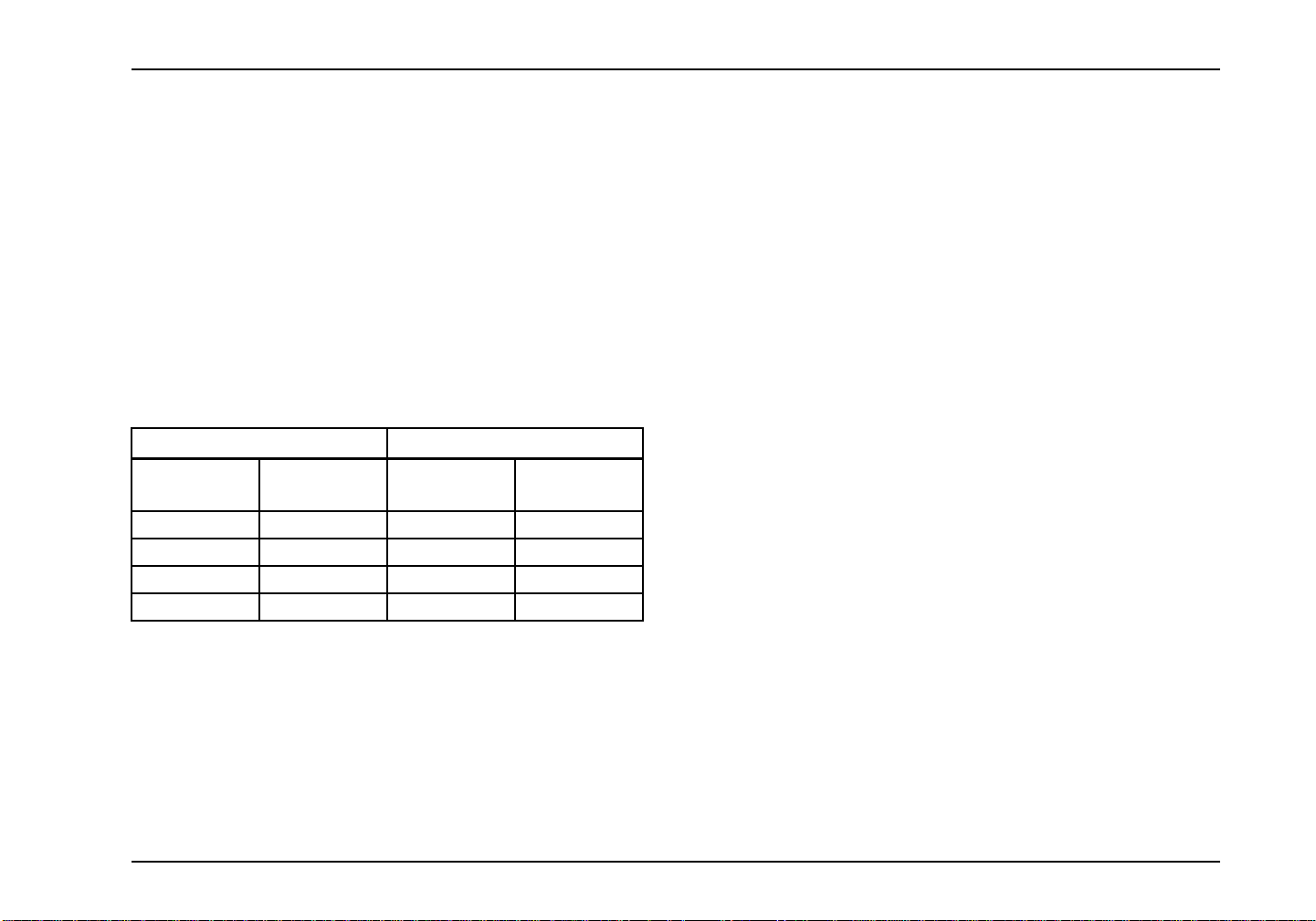
Maintenance Record – Noise Control
Chassis Model: Vehicle Identification Number:
Maintenance
Performed
Maintainer
(Name)
Location Date
Reporting Safety Defects
U.S. Registered Vehicles
(NHTSA) in addition to notifying Navistar, Inc. To notify Navistar,
Inc., see regional numbers listed in the front of the manual.
If NHTS A receives similar complaints, it may open an
investigation and, if it finds that a safety defect exists in a
group of vehicles, it may order a recall and remedy campaign.
However, NHTSA cannot become involved in individual
problems between you, your dealer, or Navistar, Inc.
To contact NHTSA, you may either call the Auto Safety
Hotline toll-free at 1-800-424-9393 (or 202-366-0123 in
Washington,D.C. area) or write to: NHTSA, U.S. Department of
Transportation, Washington, D.C. 20590. You can also obtain
other information about motor vehicle safety from the hotline.
Canadian Registered Vehicles
If you believe that your vehicle has a defect, which could cause
a crash or could cause injury or death, you should immediately
contact Navistar, Inc. Canada and then Transport Canada.
To contact Navistar, Inc. Canada, you may either call
the Regional Service Manager (Canadian Sales Region)
905-332-2357 or write to: Navistar, Inc. Canada, 5500 North
Service Road, Box 5337, Burlington, Ontario L7L 5H7.
To contact Transport Canada, Defect Investiga tionsand Recalls,
you may call 1-800-333-0510 or write to: Transport Canada,
ASFAD, P la ce de Ville Tower C, 330 Sparks Street, Ottawa,
Ontario K1A 0N5.
If you believe that your vehicle has a defect, which could cause
a crash or could cause injury or death, you should immediately
inform the N ational Highway Traffic Safety Administration
3879634R1 5
Safety Recalls and Authorized Field Changes
Safety Recalls and Authorized Field C hanges are two
campaigns that are used to notify owners of modifications
Page 18

Foreword
that may involve their vehicle. If you receive such notification,
PLEASE FOLLOW ALL INSTRUCTIONS PROVIDED IN THE
CUSTOMER LETTER. If your vehic le is part of a Safety Recall
campaign, the recall service procedure must be completed to
ensure safe operation of your vehicle. As a vehicle owner, you
must provide International dealers with address corrections and
changes to ensure that you receive all notifications. Please
verify that your local dealer has your correct address. Dealers
will also have a record of any outstanding campaigns that affect
your vehicle.
Customer Security Guide for International Trucks
This guide has been prepared to help you protect your vehicle
investment fro m theft. We realize the financial commitment you
have made is significant, and that you depend on that vehicle
to generate profits and a livelihood. Vehicle theft can be more
than an economic crime. Protecting your vehicle from theft
or hijacking can be crucial to the safety and security of the
country and economy. While no system or device is 100 percent
effective, our intention is to provide some tips that you or your
drivers can use to reduce the risk of theft.
If you suspect vehicle theft activity, take a minute to tell the
National Insurance Crime Bureau (NICB) at 1-800-TEL-NICB.
You can make the free call anonymously, and you might
be eligible for a reward. To learn more about vehicle theft
and how you can protect yourself, visit the NICB’s Web site,
www.nicb.org.
Add Layers of Protection
Four layers of protection are recommended for your vehicle - the
more layers of protection on your vehicle, the more difficult it is
to steal.
Layer 1: Common Sense
• Lock your doors.
• Remove your keys from the ignition.
• Close your wind ows com ple tely.
• Park in well-lit areas.
• Drop a business card with yourname on it betweenthe glass
and doorframe. This can aid in identifyingthe truck when it’s
recovered.
• Keep a copy of the lineset ticket in a location other than your
truck for reporting purposes and a copy of the VIN in your
wallet.
• Photograph the interior and exterior of your truck from
various angles and keep these photographs in a safe
nontruck location or send them to your insurance agent.
• Report a theft as soon as it’s discovered to the local police
and to your insurance company.
•Postadriver has no cash sign on your door to discourage a
robbery.
• Permanently m ountyour CBradio o r remove it when you will
be away from your truck.
6 3879634R1
Page 19

Foreword
• Do not discuss where your vehicle is located when you are
not on the road.
• D o not share information about y our specific destination or
the load you are hauling.
• Be conscious of other vehicles that may be following you
over long distances - call the police.
• Be suspicious of motorists that are signaling you to stop or
pull over. Call the police, report the incident, and let the
police respond.
Layer 2: Visible or Audible Device
• Audible alarm system
• Steering wheel locks
• Steering column collars
• Theft deterrent decals
• Wheel locks
• Window etching
• Mechanical or electronic steering locks that restrict the
steering shaft U-joint are easy to use and provide a very
high level of affordable theft protection.
Layer 4: Tracking System
The final layer is a tracking system that emits a signal to the
police or a monitoring service when the vehicle is reported
stolen. If your vehicle has a tracking system and is stolen, it can
oftentimes be recovered faster and with less damage.
VIN:
Model/Year:
Engine Serial Number:
License Number:
Insurance Company:
Policy Number:
Phone Number:
Other:
Layer 3: Vehicle Immobilizer
A. Fuse cutoffs
B. Kill switches
C. Starter, ignition, and fuel disablers
D. Fuel cutoff switch
3879634R1 7
Page 20

Foreword
Optional Diamond Logic® Electronic Application
Solutions
WARNING
This vehicle may be equipped from the factory
with electrical switches intended to operate
equipment that was installed by a truck
equipment manufacturer (TEM). Instructions,
Cautions, and Warnings for this additional
equipment will NOT be found in this manual.
Read and understand the appropriate manual
for the specific equipment in question before
operating. Failure to observe this warning may
causepropertydamage, personal injury,ordeath.
NOTE: This vehicle may be equipped with electronic
application-specific options not described in this Operator’s
Manual. Many of these features are supplied with rocker
switches that have custom labels applied. The presence of
these options as factory-installed can be verified from the
Line Set Ticket included with the vehicle. A truck equipment
manufacturer (TEM), however, may have installed some of
these options after production. In that case, they will not appear
ontheLineSetTicket. IfinstalledbyaTEM,youshould
receive an operating guide and/or training for the specific
functions provided. Familiarize yourself w ith all of the switches
that control chassis, engine, and body equipment and seek
adequate training on the function of all features before operating
this vehicle.
8 3879634R1
Page 21

SECTION 2 — MODEL DESCRIPTION
Model Description
Introduction
The WorkStar® Series Truck is available in a variety of models,
including the WorkStar® Series Deluxe and the WorkStar®
Series Premium. The WorkStar® Series is av aila b le in three
cab models, including the standard cab, extended cab, and the
crew cab.
This operator’s manual covers all versions. Illustrations in this
manual are used for reference only, and may differ slightly from
the actual vehicle. However, key components addressed in
the m anual are represented as accurately as possible. Models
covered are shown on the following pages.
Available Models
4x2
The 4x2 configuration includes these models 7300, 7400, 7500,
7600.
3879634R1 9
Page 22
Model Description
4x4
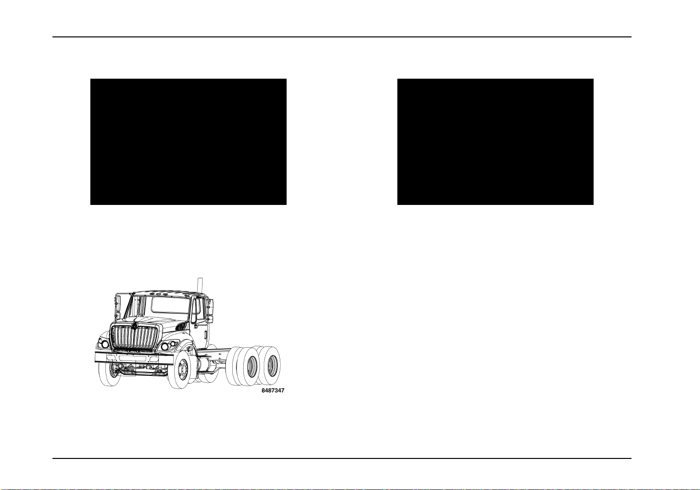
6x6
The 6x6 configura
The 4x4 configuration includes these models 7300, 7400, 7500.
6x4
The 6x4 configuration includes these models 7400, 7500, 7600.
10 3879634R1
tion includes these models 7400, 7500.
Page 23

Model Description
Available Cabs
The WorkStar® Series Truck is available with a standard cab,
extended cab, or crew cab. Each cab has its own unique
features and uses.
Standard Cab
Extended Cab
Crew Cab
3879634R1 11
Page 24
Model Description
Vehicle Identification
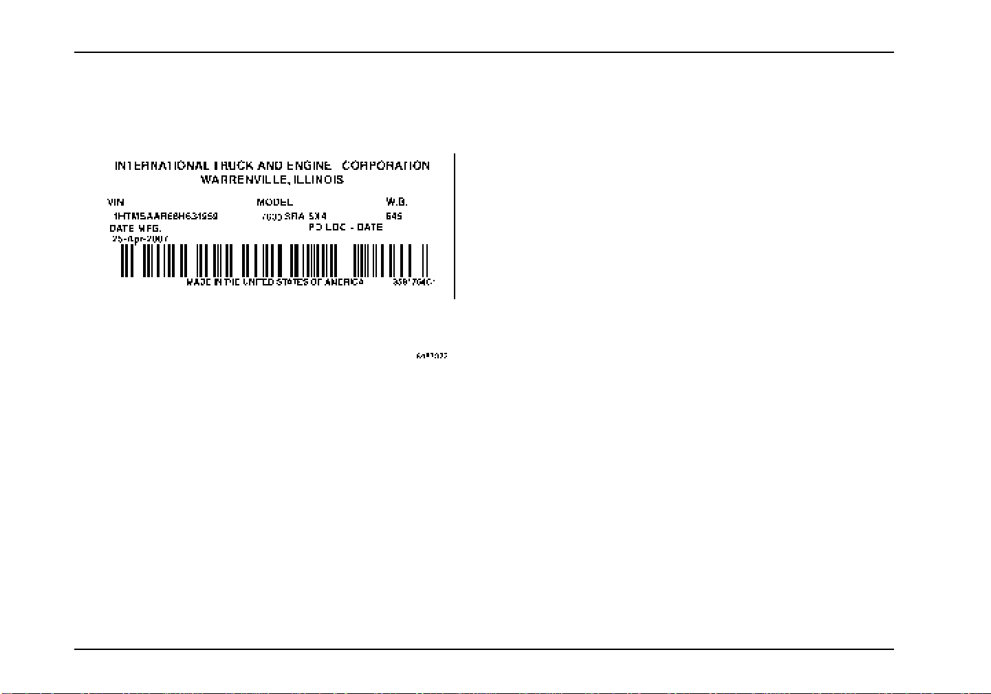
Vehicle Identification Number (VIN)
TheVehicleI
side door. Th
ordering rep
Feature Code
FeatureCodesare the basis for identifyingthecomponentsused
on International trucks. They are used by s ales personnel to
orderthe truck, by manufacturing to build that truck, and by parts
dentification Number (VIN) is located on the driver
e VIN and model description are necessary when
lacement parts or service manuals.
s
personnel to service the truck. Many items in this manual are
identified by codes.
Feature Codes are a combination of numbers and/or letters.
These codes are listed on the Line Set Ticket, which is
sometimes known as the vehicle specification card or code
sheet.
Engine Serial Number
The engine dataplate provides the engine serial number as
well as other engine information. For the location of this plate
and more information about engine components and engine
identification, refer to the Engine Operation and Maintenance
Manual.
Line Set Ticket
NOTE: Be sure to return the Line Set Ticket to the vehicle after
obtaining parts.
Each vehicle is provide d with a Line Set Ticket (code sheet)
which lists identification code numbers of component units used
to build the vehicle.
One copy of the Line Set Ticket is included in the literature
provided with the vehicle. When replacement parts are
required, take this copy with you to positively identify vehicle
components to be sure of getting the correct parts.
12 3879634R1
Page 25

Exterior Components
1. Headlight
2. Door Latch
3. Fuel Cap
4. Side Marker/Turn Light
Model Description
5. Bumper
6. Fog Light
1. Glad Hand
2. Work Ligh
3. Side Mark
4. Fuel Cap
5. Taillight
3879634R1 13
Storage Bracket
t
er/Turn Light
s
Page 26
Model Description
CabEntryandExit
WARNING
Do not step or climb upon any vehicle surface
unless it is slip-resistant and a handhold is
provided. Failure to follow this warning could
cause you to slip or fall and could result in
personal injury or death.
WARNING
A three-point stance should be used (three out
of four extremities should be in contact with
the vehicle climbing system) at all times. Face
inward towards the cab when entering and
exiting. Always keep steps and handholds in
continuous good repair. Make sure all attaching
bolts and hardware are tight, thus eliminating
any movement of steps and handholds. Keep
steps, grab handles and shoes free of grease,
mud, dirt, fuel, ice and snow. Use extra care
during inclement weather. Failure to follow this
warningcouldcauseyoutosliporfallandcould
result in personal injury or death.
Tilt Hood
WARNING
To prevent personal injury or death, never put
any part of your body beneath a raised hood
unless the hood is all the way forward in its
range of motion and is fully settled in the over
center position.
Raising the Hood
1. Before opening the hood, make sure that there is enough
room in front of the vehicle for the hood to open completely
without pinning or pinching yourself between the hood and
any other structures.
2. Release the latches on both sides of the cowl.
3. Graspthe hood handle and pullthehood forward over center
and allow it to settle into the raised position.
4. Make certain that hood is resting in the open position before
releasing hood.
Lowering the Hood
1. Make sure that the hood has no tools/parts/people in its path
of motion.
2. Grasp the hood handle and push the hood backward over
center and allow it to settle into lowered position.
3. Engage latches at both sides of cowl.
14 3879634R1
Page 27
SECTION 3 — INSPECTION GUIDE
Inspection Guide
Introduction
General Information
WARNING
To prevent property damage, personal injury or
death when servicing the vehicle, park on a flat
level service, set the parking brakes, turn the
engine off, and chock the wheels.
WARNING
Exercise care when w orking on vehicles with
running engines that are equipped with an
automatic fan clutch. The fan engages when
engine coolant reaches a predetermined
temperature or the refrigerant pressure (if
equipped with air conditioning) reaches a
predetermined setting. The fan will start with
no advance warning. Failure to observe these
precautions could result in vehicle damage,
personal injury, or death.
WARNING
If vehicle is equipped with an automatic
transmission, have a qualified technician
regularly check operation of transmission neutral
start sw itch . If unit starts in gear, the vehicle
may inadvertently move, which could result in
property damage, personal injury, or death.
To be sure your vehicle is ready to operate, conduct a pre-trip
inspection at the beginning of each work period. This section
givestheoperatorsuggestedguidelinestobeusedinperforming
tractor and trailer pre-trip inspections. Safety is the most
important and obvious reason for doing a pre-trip inspection.
Depending on the optional features of the vehicle being used
and any possible aftermarket items installed on the vehicle,
these guidelines should be modified to include other necessary
inspection points. Follow the steps in this section and check
them off to assure a proper vehicle inspection procedure. The
pages in this section may be reproduced locally and used on a
regular basis.
If any component or system does not pass this inspection, it
must be corrected before operating the vehicle. Take your time
going through the pre-trip inspection. Remember that a careful
pre-trip inspection saves time by eliminating unscheduled stops
to correct a faulty item.
3879634R1 15
Page 28

Inspection Guide
Vehicle Inspection
Preparation
NOTE: Perform the following procedures prior to conducting the
pre-trip inspection.
• Apply parking brakes.
• Turn on parking lights and hazard lights.
• Unhook the hood latches and raise the hood.
• Check under the vehicle for oil, fuel, coolant leaks, or other
signs of damage.
• Use pullcablesoropendraincockstoallowairtankstoexpel
any existing water. Release pull cables or close drain cocks.
• Chock wheels on tractor and trailer, if attached.
• S tart the engine and allow the air pressure to build up to
normal operating pressure of 115 to 130 psi (793 to 896
kPa). Stop engine.
Exterior Lights Check
TheoptionalLMPcheckswitchisusedtoperformtheexterior
lights check in the following manner:
1. Place the ignition switch in the O N or ACC position,
place the transmission in (N) Neutral, and apply the
Parking Brake.
2. Press the optional LMP check switch to activate the
system.
3. The exterior light check will now cycle all vehicle lights
except the back-up light(s). The test flashes the exterior
lights ON and OFF in three, 2-second cycles. The
first 2-second period illuminates park lights (clearance,
identification, side marke r and license plate lights),
turn signal lights, low beam head lights, fog lights.
The second 2-second period illuminates park lights
(clearance, identification, side marker and license plate
lights), high beam headlights, brake lights, work lights.
The third 2-second period turns OFF all lights. This
cycle repeats until deactivated by the operator.
4. Walk around vehicle and inspect illumination of lights.
5. To cancel this feature, do one of the following: either
press the brake pedal, manually turn ON any external
light, turn the ig nition switch to OFF or CRANK,
depress the exterior light check switch, or release
the parking brake. The feature will automatically
cancel approximately 10 minutes after activation if not
deactivated by the operator.
6. Checking the backup lights requires two people and
the engine running. Depress the clutch (if applicable)
and select reverse while the second person observes
backup light operation.
16 3879634R1
Page 29

Inspection Guide
Left Side Cab Area 1. Cab Structure: Check body panels such as doors,
air shield, sunshade, and cab for signs of breaks or
damage. Check condition of cab mounting brackets
and tilt hood latches.
2. Wipers: Check windshield wiper arms for proper spring
tension and wiper blades for damage.
3. Windshield: Check for damage to windshield and clean
if dirty.
4. Battery Box: Inspect for damage and secure mounting
of battery box. Remove battery box cover.
5. Batteries and Cables: Check that batteries are secured
and cases are not broken or leaking. Ensure cables are
free from damage. Topsof batteries and terminals must
be clean and free from foreign material. Replace battery
box cover.
6. Fuel Tank: Check to see that the fuel tank(s) and cap(s)
are secured and make sure there is no damage or leaks
at the tank(s) or fuel lines. Insure mounting straps are
secure and not chafing tank.
3879634R1 17
Page 30

Inspection Guide
Left Engine Compartment
1. Power Steering Fluid: Verify that the fluid level is
between the Cold or Hot (as applicable) MIN and MAX
marks.
2. Coolant Level: Do not remove pressure cap unless
coolant is cool. Ensure fluid level is between the
minimum and maximum fluid level range as marked on
the plastic translucent reservoir or sight glass .
3. Brake Fluid Level (if equipped): During normal vehicle
operation and servicing, the fluid level will vary between
the “MIN” and “MAX” lines on the master cylinder
mounted “front” reservoir. Do not fill the master cylinder
to the top of the reservoir. Over filling may lead to
overflow. DO NOT add fluid above MAX line.
4. Oil Level: Use dipstick to verify that the oil level is
between the full and add marks.
5. Windshield Washer Fluid Level: Inspect the reservoir
and verify that the fluid level is not empty and has
enough fluid to accomplish the upcoming mission. If
additional fluid is required, see Lubricant and Sealer
Specifications chart, in the Specification section, for
the correct fluidtypebeforefilling. Do not use water in
freezing climates.
6. Radiator and Charge Air Cooler: Check for loose
mounting and damage. Inspect condition of all hoses
for damage, cracks, and leaks. Inspect for foreign
material on face of cooling package. Carefully brush
away collected materials without bending cooling fins to
maintain prop er airflow through cooling package.
18 3879634R1
Page 31

Inspection Guide
• Fuel/Water Separator: Check sight globe (if Davco®
equipped), inform maintenance personnel if fuel level is
at top of globe, which is an indication that the filter is due
for replacement) and drain into cup periodically. Check for
leaks.
• Air Lines and Wiring: Check air Lines and electrical wiring
for proper security, and for damage, and chafing. Listen for
audible air leaks.
• Leaks: Check forsigns of fluidpuddles under vehicle, or wet
components in the engine compartment.
Check that the air dryer heater activates at temperatures
below freezing. With the vehicle in a cold environment and
before the engine is started, turn on the ignition and touch
theair dryer housing. Itshould be warmerthan other metallic
items on the vehicle. If some warmth cannot be felt it may
indicate that the heater element or the wiring powering it
should be serviced.
Left Front of Vehicle
WARNING
If wheels or tires must be changed, obtain expert
tire service help. Mounting and demounting
of tires should only be performed by qualified
personnel using necessary safety procedures
and equipment, otherwise the result could be
property damage, personal injury, or death.
3879634R1 19
Page 32
Inspection Guide
WARNING
Do not operate vehicle if any of the following
conditions are evident. Loss of steering or
suspension could cause loss of vehicle control
and result in property damage, personal injury,
or death.
WARNING
To prevent personal injury or death from
hot coolant or steam, use only the following
procedure to remove the pressure cap from the
radiator or expansion tank. Allow the engine to
cool first. Wrap a thick, heavy cloth around the
cap. Unscrew the cap slowly to allow pressure
to release from under the cap. After the pressure
has been released, the pressure cap may be
removed.
CAUTION
Retread tires are not recommended for use on
steering axles of trucks.
1. Steering Gear: Look for missing or loose fasteners,
power st eering fluid leaks, and damage to power
steering hoses.
2. Brake Chamber and Hoses: Check to see that the
brake chambers are not cracked or damaged, and are
securely mounted. Check for broken, loose, or missing
parts. Check for cracked, worn or frayed hoses, and for
secure couplings.
3. Slack Adjuster: Check slack adjuster and chamber
push rod travel. When pulled by hand, push rod
should not move more than approximately one inch.
Angle between push rod and adjuster arm should be
approximately 90 degrees when brakes are applied.
4. Brake Lining and Drum: With brakes released, check
to see that brake lin ings (where visible) are not
worn excessively thin [less than 1/4 inch (6mm)] or
contaminated by lubricant.
5. Spring Suspension: Check condition of spring for
cracks, breaks, or shifting. Inspect spring hanger
fasteners,shackles,U-bolts,and nuts for wear,damage,
and tightness.
6. Shock Absorber: Check for cracks, leaks, and missing
or broken mounting bolts or bushings.
20 3879634R1
Page 33

Inspection Guide
7. Air Suspension (if equipped): C heck for air leaks, loose
components, and damage to air bag. In spect stabilizer
bar for worn, loose, or damaged components.
8. Tires: Check tread depth and tire inflation and note if
tread is evenly worn. Minimum tread depth is 2/32 inch
on all drive tires. Look for cuts or other damage to
the tread sidewalls. See if valve caps and stems are
missing, broken, or damaged. Check dual spacing to
ensure that dual wheels, mounted on the same wheel
end, are evenly separated and that tire sidewalls are not
touching one another.
9. Wheel and Wheel Nuts: Check for damaged or bent
wheel. Check to see that all wheel nuts are present and
not loose (look for rust trails around nuts). Ensure that
no cracks or damage are present at wheel mount holes.
10. Hub: Check for obvious leaks on outside or inside of
wheel. Verify correct oil level in hub.
11. Frame: Check for cracks or bends in frame. Make sure
there are no loose, cracked, bent, broken, or missing
crossmembers or fasteners.
12. Steering Linkage: Inspect connecting links, arms, rods,
and steering intermediate shaft for w orn, damaged,
loose, or missing components.
3879634R1 21
Page 34
Inspection Guide
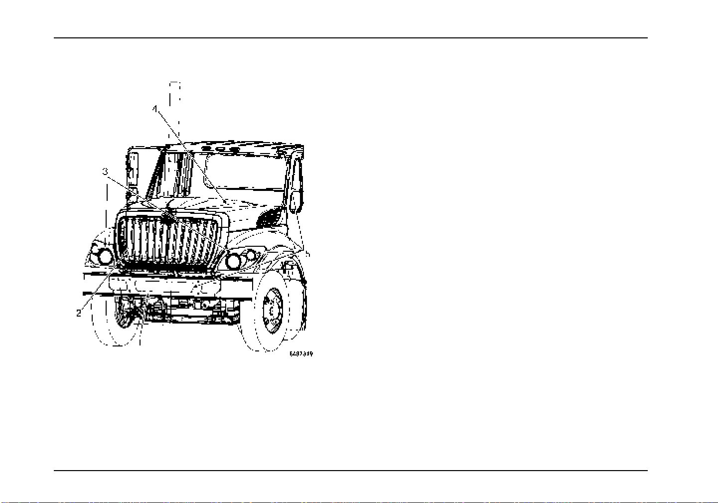
Front of Vehicle 1. Bumper: Inspect for damage and security.
2. Grille: Inspect for damage and security. Check bug
screen for damage and cleanliness.
3. Headlights: Lenses should be clean. If equipped, check
daytime running lights.
4. Hood and Fenders: Check hood panels and fenders for
signs of breaks or damage. Ensure hood opens and
closes properly.
5. Lighting System: Lower hood and inspect parking,
clearance, identification lights, turn signals, fog lights,
and reflectors on hood, bumper, and cab. They should
be clean, operational and the proper color Inspect for
damage and security.
22 3879634R1
Page 35
Inspection Guide
Right Front of Vehicle
WARNING
To prevent personal injury or death when
performing maintenance and repairs to any
turbocharged engine with engine air inlet piping
disconnected, a turbocharger compressor air
inlet protective shield should be installed over
the turbocharger air inlet.
WARNING
Electrical circuits are designed with a particular
wire gauge to meet the fuse and circuit breaker
current rating. Do not increase size of fuse or
circuitbreakerorchangetype of breaker supplied
with your truck. To do so could cause wiring to
overheat and possibly burn, resulting in a fire
which could cause property damage, personal
injury, or death.
1. Spring Suspension: Check condition of spring for
cracks, breaks, or shifting. Inspect spring hanger
fasteners,shackles, U-bolts, and nuts for wear,damage,
and tightness.
2. Shock Absorber: Check for cracks, leaks, and missing
or broken mounting bolts or bushings.
3. Air Suspension (if equipped): Check for air leaks, loose
components, and damage to air bag. Inspect stabilizer
bar for worn, loose, or damaged components.
3879634R1 23
Page 36

Inspection Guide
4. Frame: Check for cracks or bends in frame. Make sure
there are no loose, cracked, bent, broken, or missing
crossmembers or fasteners.
5. Brake Chamber and Hoses: Check to see that the
brake chambers are not cracked or damaged, and are
securely mounted. Check for broken, loose, or missing
parts. Check for cracked, worn or frayed hoses, and for
secure couplings.
6. Slack Adjuster: Check slack adjuster and chamber
push rod travel. When pulled by hand, push rod
should not move more than approximately one inch.
Angle between push rod and adjuster arm should be
approximately 90 degrees when brakes are applied.
7. Brake Lining and Drum: With brakes released, check
to see that brake linings (where visible) are not
worn excessively thin [less than 1/4 inch (6mm)] or
contaminated by lubricant.
8. Hub: Check for obvious leaks on outside or inside of
wheel. Verify correct oil level in hub.
9. Wheel and Wheel Nuts: Check for damaged or bent
wheel. Check to see that all w heel nuts are pres ent and
not loose (look for rust trails around nuts). Ensure that
no cracks or damage are present at wheel mount holes.
10. Tires: Check tread depth and tire inflation and note if
tread is evenly worn. Minimum tread depth is 2/32 inch
on all drive tires. Look for cuts or other damage to
the tread sidewalls. See if valve caps and stems are
missing, broken, or damaged. Check dual spacing to
ensure that dual wheels, mounted on the same wheel
end, are evenly separated and that tire sidewalls are not
touching one another.
11. Steering Linkage: Inspect connecting links, arms, and
rods for worn, damaged, loose, or missing components.
24 3879634R1
Page 37

Inspection Guide
Right Engine Compartment
1. Cowl Vent: Ensure air inlet cover is free of dirt and
debris.
2. Air Cleaner: Check air cleaner element, housing, and
hoses for loose connections or damage. Check filter
minder gauge for restriction reading. For element
replacement, see Air Clean er Element Service in the
Maintenance section.
3. Drive Belts: Inspect all belts f or frays, cracks, loo se
fibers, or visible sign s of wear. With engine off, press
on all belts to test for proper belt tensioner performance
4. Radiator and Charge Air Cooler: Check for loose
mounting and damage. Inspect condition of all hoses
for damage, cracks, and leaks. Inspect for foreign
material on face of cooling package. Carefully brush
away collected materials without bending cooling fins to
maintain proper airflow through cooling package.
• Air Lines and Wiring: Check air Lines and electrical wiring
for proper security, damage, and chafing. Listen for audible
air leaks.
• Leaks: Check for signs of fluid puddles under vehicle, or wet
components in the engine compartment.
3879634R1 25
Page 38

Inspection Guide
Right Side of Cab CAUTION
Do not adjust air suspensionheight to any setting
other than the specified setting. Altering the
height setting w ill change the driveline angle and
may result in unwarrantable component damage,
such as transmission component damage.
1. Cab Structure: Check body panels such as doors,
fenders, and cab for signs of breaks or damage. Check
condition of cab mounting brackets and tilt hood latches
and where the torsion bars are mounted to hood.
2. Fuel Tank: Check to see that the fuel tank and cap are
secured and make sure there is no damage or leaks at
the tank, fuel lines, or tank mounting hardware is secure
.
26 3879634R1
Page 39

Inspection Guide
Right Side Under Vehicle
WARNING
Maintain adequate clearance between all parts of
the exhaust system and all hoses, wires and lines
for engine cooling, brake system, fuel system,
power steering system and electrical system.
Heat damage to hoses, wires may cause vehicle
malfunctionthat could result in property damage,
personal injury, or death.
1. Frame: Check for cracks or bends in frame. Make sure
there are no loose, cracked, bent, broken, or missing
crossmembers or fasteners.
2. Exhaust System: Check to see that all component parts
are securely mounted and no cracks, holes, or severe
dents are visible. Evidence of soot build up around
clampsor connections is a clear indicatorof a leak being
present. Ensure that all hoses, wires, and air lines are
secured away from exhaust components.
3. Transmission: Inspect for leaks.
4. Drive Shaft: Ensure that all shaft couplings are secure.
• Air Lines and Wiring: Check air Lines and electrical wiring
for proper security, damage, and chafing. Listen for audible
air leaks.
3879634R1 27
Page 40

Inspection Guide
Right Rear of Vehicle
WARNING
If wheels or tires must be changed, obtain expert
tire service help. Mounting and demounting
of tires should only be performed by qualified
personnel using necessary safety procedures
and equipment, otherwise the result could be
property damage, personal injury, or death.
1. Brake Chamber and Hoses: Check for cracked, worn
or, frayed hoses, and for secure couplings. Check to
see that the brake chambers are not cracked or dented
and that they are securely mounted. Check for broken,
loose, or missing parts.
2. Slack Adjuster: Check slack adjuster and chamber
push rod travel. When pulled by hand, push rod
should not move more than approximately one inch.
Angle between push rod and adjuster arm should be
approximately 90 degrees when brakes are applied.
3. Brake Lining and Drum: With brakes released, check
to see that brake lin ings (where visible) are not
worn excessively thin [less than 1/4 inch (6mm)] or
contaminated by lubricant.
4. Wheel and Wheel Nuts: Check for damaged or bent
wheel. Check to see that all w heel nuts are pres ent and
not loose (look for rust trails around nuts). Ensure that
no cracks or damage are present at wheel mount holes.
28 3879634R1
Page 41

Inspection Guide
5. Tires: Check tread depth and tire inflation and note if
tread is evenly worn. Minimum tread depth is 2/32 inch
on all drive tires. Look for cuts or other damage to
the tread sidewalls. See if valve caps and stems are
missing, broken, or damaged. Check dual spacing to
ensure that dual wheels, mounted on the same wheel
end, are evenly separated and that tire sidewalls are not
touching one another.
6. Hub: Check for obvious leaking on outside or inside of
wheel. Inspect axle flanges and wheel seals for leaks
and loose mounting hardware or broken items. Check
lube le vel, if equipped with sight glass.
7. Spring Suspension: Check condition of spring for
cracks, breaks, or shifting. Inspect spring hanger
fasteners, shackles,U-bolts, an d nutsfor wear,damage,
and tightness.
8. Torque Rods and Shock Absorbers: Check to see that
torque rods are not cracked, broken or missing. Check
shock absorbers for cracks or leaks. There should be
no missing or, broken mounting bolts or worn bushings .
9. Air Suspension (if equipped): Check for air leaks, loose
components,and damage to air bag. Inspect ride height
valve and linkage for damage.
10. Frame: Check for cracks or bends in frame. Make sure
there are no loose, cracked, bent, broken, or missing
crossmembers or fasteners.
• A ir Lines and Wiring: Check air lines and electrical wiring for
proper security, damage, and chafing. Listen for audible air
leaks.
3879634R1 29
Page 42

Inspection Guide
Rear of Vehicle 1. Lights and Reflectors: Check to see that reflectors and
lights are clean. Make sure none are missing or broken.
Rearrunning lights shouldbe clean, not broken, and red
in color.
2. Frame: Check for cracks or bends in frame. Make sure
there a re no loose, cracked, bent, broken, or missing
crossmembers or fasteners.
3. Mud flaps: Inspect rear mud flaps and mountings for
damage and proper security.
• Air Lines and Wiring: Check air Lines and electrical wiring
for proper security, and for dama ge, and chafing. Listen for
audible air leaks.
30 3879634R1
Page 43
Inspection Guide
Left Rear of Vehicle
WARNING
Due to tire manufacturers re-marking tires to
conform to the SI (metric) system, tires marked
with old and new loads or inflation pressures
could be placed on the same vehicle. For field
maintenance, only inflateandloadtirestothe
maximum of the least-rated tire on the axle.
Failure to adhere to this warning could possibly
result in tire malfunction, damage to your vehicle,
personal injury, or death.
1. Brake Chamber and Hoses: Check for cracked, worn,
or frayed hoses, and for secure couplings. C heck to
see that the brake chambers are not cracked or dented
and that they are securely mounted. Check for broken,
loose, or missing parts.
2. Slack Adjuster: Check slack adjuster and chamber
push rod travel. When pulled by hand, push rod
should not move more than approximately one inch.
Angle between push rod and adjuster arm should be
approximately 90 degrees when brakes are applied.
3. Brake Lining and Drum: With brakes released, check
to see that brake linings (where visible) are not
worn excessively thin [less than 1/4 inch (6mm)] or
contaminated by lubricant.
4. Frame: Check for cracks or bends in frame. Make sure
there are no loose, cracked, bent, broken, or missing
crossmembers or fasteners.
3879634R1 31
Page 44

Inspection Guide
5. Wheel and Wheel Nuts: Check for damaged or bent
wheel. Check to see that all wheel nuts are present and
not loose (look for rust trails around nuts). Ensure that
no cracks or damage are present at wheel mount holes.
6. Tires: Check tread depth, tire inflation and note if tread
is evenly worn. Minimum tread depth is 2/32 inch on all
drive tires. Look for cuts or other damage to the tread
sidewalls. See if valve caps and stems are missing,
broken or damaged. Check dual spacing to ensure that
dual wheels are evenly separated, and that tires are not
touching one another.
7. Hub: Check for obvious leaking on outside or inside of
wheel. Inspect axle flanges and wheel seals for leaks
and loose mounting hardware or broken items. Check
lube level, if equipped with sight glass.
8. Spring Suspension: Check condition of spring for
cracks, breaks, or shifting. Inspect spring hanger
fasteners,shackles,U-bolts,and nuts for wear,damage,
and tightness.
9. Torque Rods and Shock Absorbers: Check to see that
torque rods are not cracked, broken, or missing. Check
shock absorbers for cracks or leaks. There should be
no missing or broken mounting bolts or worn bushings.
10. Air Suspension (if equipped ) Check for air leaks, loose
components, and damage to air bag. Inspect ride height
valve and linkage for damage.
• Air Lines and Wiring: Check air Lines and electrical wiring
for proper security, damage, and chafing. Listen for audible
air leaks.
32 3879634R1
Page 45
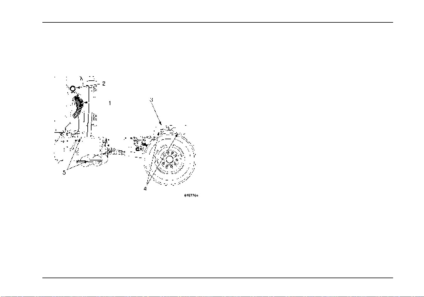
Inspection Guide
FifthWheelandCouplingArea 1. Trailer Coup ling Cords: Inspect air lines and coupling
gaskets, electrical cord for cuts, chafing, damage, and
proper security. Check air lines for audible air leaks .
2. Work Light(s): Check operation and clean as needed.
3. Lubrication: Make sure that top surface (face) of the 5th
wheel has a coat of grease.
4. Mounting Bolts and Release Handle: Look for loose
or missing mounting brackets, clamps, bolts, or nuts.
All locking pins must be in place and free of damage.
Ensure that release handle is in the engaged position
and the safety latch is functioning and free of damage.
5. Deck Plate and Access Steps: Check to ensure that the
deck plate and steps are clean, securely bolted in place,
and clear of loose objects.
3879634R1 33
Page 46

Inspection Guide
Cab Interior Inspection
1. Safety/Emergency Equipment: Prior to entering
cab, verify that vehicle is equipped with the proper
equipment. Walk around vehicle and check that all
steps and grab handles, inside and out, as well as
behind, are tight and clean. Use extreme caution and
maintain 3 point contact at all times.
2. Doors: Check door latches for positive closing, latching
and locking.
3. Clutch/Gearshift: Depress clutch pedal (if present ) and
verify transmissionis in neutral before turnin g on starter;
keep depressed until engine reaches idling speed and
vehicle in neutral.
4. Oil Pressure Builds: Check to see that oil pressure is
building to a normal level. Engine oil pressure gauge
should begin a gradual rise to normal operating range.
5. Low Air Alarm: The low air pressure alarm may sound
immediately after the engine starts but before the air
compressor has built up minimum 5 5 psi pressure.
The low air pressure alarm should stop when the air
pressure reaches 60 to 76 psi (414 to 524 kPa). Let the
air pressure build to governor cut-out pressure, which
should occur between 115 and 130 psi (793 and 896
kPa).
6. Accelerator: Depress accelerator pedal and verify that it
operates smoothly without any binding or irregular feel.
Remove foot from accelerator and make sure engine
returns to idle immediately.
7. Voltmeter: Check the gauge to see if the alternator is
charging between 12.5 and 14.5 volts.
8. Steering Play: Check for smooth operation. Check
for excessive looseness in the steering linkages. The
steering wheel should have less than 10 degrees free
play (approximately 2 inches at rim of 18 inch steering
wheel).
9. Seats: Be sure seats are firmly engaged to avoid
forward or rearward movement when starting or
stopping. Make sure that seats and tether straps
arefreefromdamageandsecuredtofloor.
10. Horn(s): Check to see that horn(s) operate properly.
11. Mirrors: Check mirrors for proper adjustment, damage,
cleanliness, and proper mounting. Check (optional)
power mirrors and (optional) heated mirrors for proper
operation.
12. Doors: Ensure windows are clean and operate properly
and smoothly in both doors.
13. Windshield and Wipers: Check windshield for cracks,
dirt, illegal stickers or other obstructions to view. Ensure
wipers and windshield washer are functioning properly.
14. Lighting Indicators: Check to see that dash indicators
illuminate when corresponding lights are turned on.
15. Heater/Defroster: Check to be sure that heater/defroster
is working. Verify adequate air flow from louvers and
vents. OperateTemperature and Mode controls to verify
proper operation.
34 3879634R1
Page 47

16. Air Brake Check: Check the air brakes in the following
manner:
a. Chock wheels if necessary. Pushin parking
brake and start engine.
b. Check for air compressor or governor cut-
out pressure at 125 to 13 5 psi (862 to 931
kPa). Shift into a low gear, and gently
pull against service and parking brakes
separately to make sure they hold.
c. Shutoff engine and TURN IGNITIONBACK
ON.
d. Without brake pedal applied, note air
pressure drop for one minute. It should
belessthan2psi(14kPa).
e. Depress and hold brake pedal and make
surethereisnomorethana3psi(21kPa)
per minute pressure drop. For combination
vehicles,thereshouldbenomorethan4psi
(28 kPa) per m inute pressure drop.
Inspection Guide
f. Step on and off brake pedal and check that
warning light and alarm come on at about
60 or 76 psi (414 or 524 kP a).
g. Step on and off brake pedal and check to
make sure the parking brake knobs pop out
between 20 and 45 psi (138 and 310 kPa).
3879634R1 35
Page 48

Inspection Guide
36 3879634R1
Page 49

SECTION 4 — CONTROLS/FEATURES
Controls/Features
Introduction
The controls/features enable the driver to monitor and manage
the operation of the majority of the vehicle’s functions. This
section describes and identifies various components within the
Overhead Console, Instrument Panel Gauge Cluster, Center
Dash Panel/Wing Panel, Steering Column and Switches,
Steering Wheel Controls, Door and Window Controls, and
Vehicle Information Display.
Electrical
WARNING
This vehicle may be equipped from the factory
with electrical switches intended to operate
equipment that was installed by a truck
equipment manufacturer (TEM). Instructions,
Cautions, and Warnings for this additional
equipment will NOT be found in this manual.
Read and understand the appropriate manual
for the specific equipment in question before
operating. Failure to observe this warning may
causepropertydamage, personal injury,ordeath.
NOTE: This vehicle may be equipped with electronic,
application-specific options not described in this Operator’s
Manual. Many of these features are supplied with rocker
switches that have custom labels applied. The presence of
these options as factory installed c an be verified from the
Line Set Ticket included with the vehicle. A truck equipment
manufacturer (TEM), however, may have installed some of
these options after production. In that case, they will not appear
on the Line Set Ticket. If installed by a TEM, you should
receive an operating guide and/or training for the specific
functions provided. Familiarize yourself with all of the switches
that control chassis, engine, and body equipment and seek
adequate training on the function of all features before operating
this vehicle.
Electrical System
The electrical system provides a means to distribute the
electrical power and provide the driver with controls and
indications of vehicle performance. Unlike previous electrical
systems, this system uses multiplexing for connecting to
major functional areas of the truck with much less wiring. The
system provides interfaces to a majority of vehicle switches
and sensors and communicates with the standard and optional
system controllers and modules in the vehicle.
3879634R1 37
Page 50
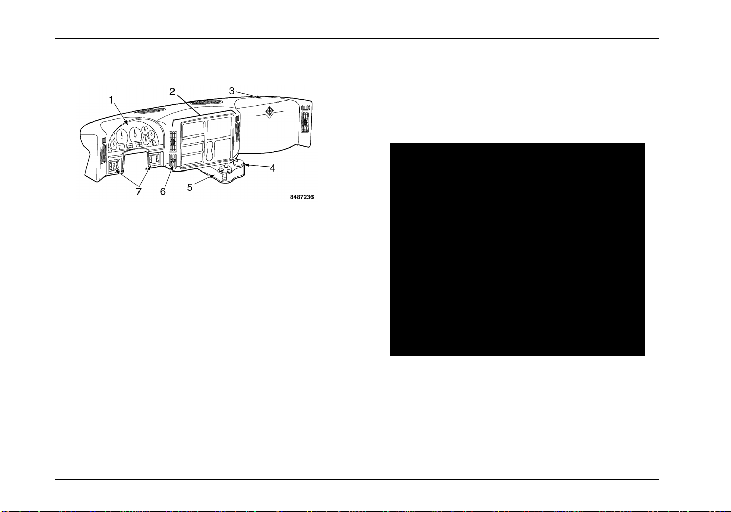
Controls/Features
Dash Components
1. Instrument Panel Gauge Cluster
2. Center Dash Panel/Wing Panel
3. Fuse Panel Cover
4. Ashtray
5. Cup Holder
6. Ignition Switch
7. Lower Panel Switches
Overhead Console
This vehicle is equipped with an overhead console that provides
both dome lighting and storage facilities. The overhead storage
capacity consists of two netted storage bins large enough to
place many items (one for the driver and one for the passenger).
1. Storage p
2. Sun Visor
3. Dome Lamp S
4. Optional C
38 3879634R1
ockets
s
witch
ompass/Temperature Display
Page 51

Controls/Features
Main Instrument/Control Panel
Instrument Panel Gauge Cluster
The instrument panel gauge cluster includes the instrument
gauges, warning indicators, and an Integral Digital Display, that
provide odometer, transmission gear indication, and compass
heading and outside temperature displays. This instrument
panel gauge cluster displays the crucial operational functions
of the vehicle. The following are descriptions and illustrations
of the gauges, warning indicators, and integral digital display
options.
3879634R1 39
Page 52

Controls/Features
40 3879634R1
Page 53
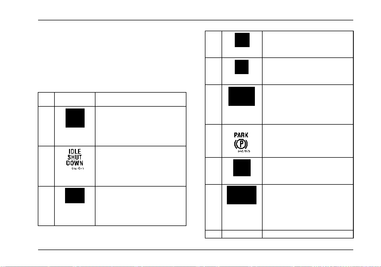
Controls/Features
Warning Indicators
The instrument panel gauge cluster contains 25 individual LED
warning indicators. These indicatorsare used to monitor vehicle
operation and indicate a WARNING or STOP condition. These
warning indicators are driven by the software in the instrument
panel gauge cluster. At ignition, the warning indicators will
illuminate for 8 to 10 seconds, as part of the vehicle power-up
sequence.
Item
No.
1 Illuminates Yellow when the intake
2 Illuminates Yellow to alert driver that
3 Illuminates Yellow.Usedinconjunction
Item Description
heaters and glow plugs are in operation
and special starting procedures are
required. Refer to the Starting Switch
paragraph in the Vehicle Operation
section for more information.
vehicle idle shutdown timer will turn
engine off in 30 seconds.
with other Warning Indicators or General
Text and Warning Messages and may
be accompanied by an audible alarm
to i ndi cate an Alert condition to the
operator.
4 Illuminates Yellow.Usedinconjunction
with other Warning Indicators or General
Text and Warning Messages to indicate
an Alert condition to the operator.
5 Illuminates Red Used in conjunction with
other Warning Indicators or General Text
andWarningMessagestoindicateared
STOP alert.
6 Illuminates Red when a failure in the
service brake system has occurred. If
the Brake Pressure warning indicator
illuminates, safely stop the vehicle as
soon as possib le and seek service
immediately.
7 Illuminates Red when the parking brake
is applied. If the brake warning indicator
does not illuminate, or if it stays on with
the parking brake not engaged, seek
service immediately.
8 Illuminates Green to assist operators
in determining when it is appropriate to
shift the transmission to a h igher gear in
order to maximize driving fuel economy.
9 Illuminates Yellow when the
transmission is not engaged in the
selected gear. The warning indicator
goes out when the gearshift lever is
adjusted to the appropriate gear. Refer
to the Transmission Operator’s Manual
for more information.
10 Not used.
3879634R1 41
Page 54
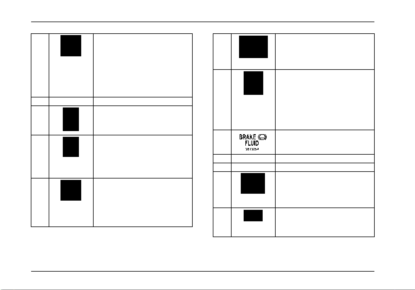
Controls/Features
11 Illuminates Yellow when the traction
control system is turned off. It also
illuminates momentarily when the
traction control system is on and is
limiting wheel spin. Indicator blinks if
slippery road conditions exist. If this
happens, adjust your driving accordingly.
Refer to the Operation section for more
information.
12 Not used.
13 Illuminates Yellow when exhaust system
components are operating under normal
conditions and exhaust gases are at
extremely high temperatures.
14 Diesel Particulate Filter (DPF) status
indicator. Illuminates Yellow (Solid
or Flashing) to indicate the need to
regenerate the Diesel Particulate Filter.
(See Exhaust Regen in the Vehicle
Operation Section).
15 Engine Emissions Control System
Malfunction Indicator Lamp (MIL)
Illuminates Yellow when an emissions
problem has occurred.
16 Illuminates Red when a parking brake
system malfunction has been detected.
If the Service Parking Brake indicator
stays illuminated, h ave the system
serviced immediately.
17 Optional indicator illuminates Red
immediately after ignition is turned on to
remind operator to fasten seat belt.
Optional Seat Belt Reminder with Seat
Belt Monitoring causes initial visual
indication, then flashes with audible
alarm when ignition is on, parking brake
is released, and seat belt is not fastened.
18 Illuminates Red when the brake fluid
falls below the sa fe operating level.
19 Not used.
20 Not used.
21 Illuminates Yellow when an antilock
brake system malfunction has been
detected. If the ABS indicator stays
illuminated or continues to flash, have
the system serviced immediately.
22 Illuminates Yellow when transmission
Economy Mode is selected. Refer to
the Transmission Operator’s Manual for
more information.
42 3879634R1
Page 55
Controls/Features
23 Flashes Green when the left turn signal
or the hazard lights are turned on.
24 Illuminates Blue when the
head lamps are turned on.
25 Flashes Green when the rig ht turn signal
or the hazard lights are turned on.
high beam
NOTE: If the MIL is illuminated, it is the vehicle owner’s
responsibility to have the engine repaired or face fines.
Gauges
There are six standard and four optional gauges in the
instrument panel gauge cluster to help monitor the vehicle
while in service. Most gauges have in-gauge warning
indicators which turn ON if the gauge pointer moves into
an out-of-acceptable-range condition. When the ignition switch
is turned ON, the gauge indicators will be ON. If any indicator
fails to go out after starting engine, stop engine and determine
cause of the gauge indication that is out of acceptable range.
Metric versions of the gauges and speedometer are available
as an option.
Item
No.
26 Transmission Oil TemperatureGauge:
27 Optional Engine Oil Temperature
27 Optional Ammeter: Indicates the rate
28 Coolant Temperature Gauge:
Item Description
Indicates the transmission lubricant
temperature in degrees Fahrenheit or
Celsius.
Gauge: Indicates the engine lubricant
temperature in degrees Fahrenheit or
Celsius.
of charge of electric current supplied by
the alternator to the battery, or the rate
of discharge from the battery.
Indicates engine coolant temperature.
The warning indicator indicates the
engine coolant temperature has
exceeded 230° F when equipped
with a 10 psi de-aeration tank, and
235° F when equipped with a 15 psi
de-aeration tank. If the warning indicator
is activated, stop the vehicle as soon as
safely possible, turn off the engine and
let the engine cool.
3879634R1 43
Page 56
Controls/Features
Item
No.
29 Engine Oil Pressure Gauge: Indicates
30 Tachometer: Indicates the engine
31 Speedometer: Indicates vehicle speed.
Item Description
engine oil pressure. If the needle falls
below the normal range (20–65 psi) at
normal operating temperature, stop the
vehicle as soon as safely possible, and
check the engine oil level. Add oil if
needed. If the oil level is correct, have
your vehicle checked by a qualified
technician.
The warning indicator indicates low
engine oil.
speed in revolutions per minute.
Item
No.
32 Fuel Level Gauge: Indicates the
33 Battery Voltage Gauge: Indicates the
Item Description
approximate fuel level in the fuel tank. If
your vehicle is equipped with dual fuel
tanks, th e fuel gauge reads the fuel level
only from the primary (draw) fuel tank.
When the fuel level reaches 1/8 full, the
gauge warning indicator will illuminate
and an audible alarm will sound (5
beeps).
(Optional) Special fuel warning: the
warning indicator will light when gauge
falls below 1/3, and alarm continuously
whenbelow1/10(closeto”E”).
voltage when the key is in the ON or
ACCESSORY position.
The warning ind icator illuminates when
the battery voltage is too high or low.
44 3879634R1
Page 57
Controls/Features
Item
No.
34 Air Pressure Gauge 1: Provides
35 Air Pressure Gauge 2: Provides
Item Description
indication of air pressure available for
the primary air brakes. LED and au dible
under-limit (less than 57 psi) warning
indicators.
indication of air pressure available for
the secondary air brakes. LED and
audible und er-limit (less than 57 psi)
warning indicators.
Instrument Panel Gauge Cluster Alarms
WARNING
When an alarm sounds, stop normal vehicle
operation and determine the source of the alarm
condition. Failure to observe this instruction
could result in property damage, personal injury,
or death.
TheInstrument Panel Gauge Clusterwill sound an audiblealarm
that accompanies out of range gauge readings along with the
particular gauge warning indicators. The cluster alarms will also
sound when any engine sensor (sender) unit fails; when there is
anelectronicssystemfault; and when the Red engine indicator is
illuminated. The following chart lists the num ber of alarm beeps
for the above conditions or warning states:
Alarm Conditions Audible Alarm Pattern Additional Comments
Fuel Level Gauge low (alarms on each ignition turn-on and
low fuel occurrence)
Voltmeter Gauge out of range reading 5 BEEPS
Engine Oil Pressure Gauge out of range rea ding 5 BEEPS
3879634R1 45
5 BEEPS Instrument Panel Gauge Cluster warning indicator
illuminates.
Page 58
Controls/Features
Alarm C onditions Audible Alarm Pattern Additional Comments
Engine Oil Temperature Gauge out of range reading 5 BEEPS Instrument Panel Gauge Cluster w arning indicator
illuminates.
Engine Coolant Temperature Gauge out of range reading 5 BEEPS Instrument Panel Gauge Cluster warning indicator
illuminates.
Transmission Oil Temperature Gauge out of range reading 5 BEEPS Instrument Panel Gauge Cluster w arning indicator
illuminates.
Rear-Rear Axle Oil Temperature Gauge out of range reading 5 BEEPS Instrument Panel Gauge Cluster warning indicator
illuminates.
Forward-Rear Axle Oil Temperature Gauge out of range
reading
Auxiliary Air Pressure Gauge out of range r eading 5 BEEPS Instrument Panel Gauge Cluster warni ng indicator
Gauge Sensor Faults 3 BEEPS Gauge pointer goes to 6 o’clock position and
Primary Air Pressure Gauge out of range and air pressure
sensor fa ult
Secondary Air Pressure G auge out of range and air pressure
sensor fa ult
RedStopWarningindicator illuminates REPEATING SINGLE
Turn Signal Alarm (Optional) CONTINUOUS TONE Alarm sounds if either turn signal is on for more than
5 BEEPS Instrument Panel Gauge Cluster warning indicator
illuminates.
illuminates.
Instrument Panel Gauge Cluster warning indicator
illuminates.
REPEATING SINGLE
BEEP
REPEATING SINGLE
BEEP
BEEP
Instrument Panel Gauge Cluster warning indicator
illuminates.
Instrument Panel Gauge Cluster warning indicator
illuminates.
Instrument panel warning indicator illuminates.
one mile.
Will not activate when hazard flashers are on.
Low Coolant Alarm REPEATING SINGLE
BEEP
Gauge warning indicator illuminates.
46 3879634R1
Page 59
Controls/Features
Direct Drive Warning Indicators
The direct drive warning indicators give information to the
operator of various conditions of the vehicle. Eight spaces are
available for the direct drive warning indicators. Blank cover
plates will be used in spaces that do not have direct drive
warning indicators installed at those locations.
Item
No.
36 Yellow WINTER/ENGINE INTAKE
37 Yellow Front rear axle diffe
38 Yellow Rear rear axle differential is
39 Yellow FRONT AXLE/ON switch is
40 BLANK Not used
40 BLANK Not used
41 BLANK Not used
41 BLANK Not used
42 Yellow AUTO NEUTRAL function
Item Color Description
is set to the Winter position.
rential
is locked.
locked.
in the ON position.
enabled.
Item
No.
43 Yellow Optional Transmission
43 Yellow Illuminates in conjunction
Item Color Description
Retarder switch is in the ON
position.
with the (Optional)
Qualcomm satelite
communication system
– see Qualcomm system
owner’s manual.
Integral Digital Display
The Integral Digital Display is located below the speedometer
and the tachometer. It is arranged in four quadrants that display
vehicle information. The four quadrants can be individually
selected by using the display control button.
Display Control. TheDisplaycontrolisusedtoscrolltoa
quadrant and to select the various modes within a quadrant. To
navigate between quadrants, turn and release the control either
clockwise or counterclockwise. To select the s creens within a
quadrant, press and release the control. Pressing and holding
the control for more than 3 seconds to reset the value of the
selected quadrant parameter (if the parameter can be reset).
The selected quadrant is identified by a vertical bar located in
the far right of quadrant. In quadrant 1, the odometer screen
canbetoggledbetweenEnglishandMetric,bypressingand
holding the control.
3879634R1 47
Page 60

Controls/Features
Item No. Quadrant Number and Me ssage Function Message Description
44 Quadrant 4: Transmission Gear Indication Transmission gears for the Allison P-R-N - D-L gear selection display, or the
Eaton Transmission display.
45 Quadrant 1: Informational Messages Informational Display Screens:
•Odometer
•TripOdometer
• Total Engine Hours
• Trip Hours
• Machine PTO A or B Hours
• Machine Trip PTO A or B Hours
•EnginePTOHours
• Engine PTO Trip Hours
• Instantaneous Fuel Economy
• Trip Average Fuel Economy
• Machine PTO Fuel Used A or B
• Machine PTO Trip Fuel Used A or B
• Engine PTO Fuel Used
• Engine PTO Trip Fu el Used
• Trip Idle Fuel Used
• Axle Load Indication (Front and/or Rear)
• Diesel Particulate Filter Level
48 3879634R1
Page 61
Controls/Features
Item No. Quadrant Number and Message Function Message Description
46 Quadrant 2: General Text and Warning
Messages
47 Quadrant 3: Compass Heading/Outside
Temperature
48 Display Control Togg les the information display from one screen to the next when pressed
Displays a variety of messages ranging in priority necessary for vehicle
monitoring and operation, and vehicle malfunction warnings. Some messages
are used in conjunction with instrument panel gauge cluster warning indicators
(see list of messages in the Integral Digital Display section in Vehicle Operations)
(Optional) Displays compass heading when vehicle is equipped with a compass
module.
Displays outside temperature (reading is obtained from the temperature sensor).
and released.
Switches
Six switches are located on the lower left and right side of the
main instrument/control panel. Configurations are optional.
Blank cover plates will be used in spaces that do not have
switches installed at those locations.
Headlights
The headlights will be at 100 percent brightness with the
headlight switch activated. The park lights, tail lights, markers,
and clearance lights will be on as well.
Your vehiclemay be equipped with an optionalheadlightwarning
alarm that sounds immediately after ignition switch is turned to
OFF position, when headlight switch is on, and the driver’s door
is closed. It also sounds when headlight switch is on, ignition
switch is in OFF position, and the drivers door is open.
The headlights are operated in a variety of modes:
3879634R1 49
Daytime Running Lights (DRL)
The daytime running lights feature provides for low beam
headlights at 75 percent brightness whenever the Parking
Brake is released and the ignition switch is in the ON position.
The lights will stay ON until the Parking Brake is engaged.
Lights on with Wipers
Thisfeatureallowstheheadlights(low beam) to be automatically
turned ON when the windshield wipers are in steady o r
intermittent mode (not washer). The low beams will remain
ON until the ignition switch is turned to the OFF position or the
headlights are cycled ON and then OFF.
Park Lights
The park lights, taillights, markers, and c learance lights will turn
ON when the headlight switch is in the park or headlightposition.
Page 62

Controls/Features
Marker Interrupt
The marker interrupt function is an optional feature that toggles
the park lights and markers when the operator activates the
spring-loaded marker interrupt switch. When park lights are
ON, activating the interrupt switch will cause the park lights and
markers to be turned OFF until the interru pt switch is released.
If park lights are OFF, activating the interrupt switch will cause
the park lights and trailer markers to be turned ON until the
switch is released.
Panel Lighting
The panel lighting brightness is controlled by the Panel rocker
switch. To increase the brightness of the instrument panel
lighting, continually press the upper portion of the rocker switch.
To dim the instrument panel lighting, continually press the lower
portion o f the rocker switch.
Dome Lighting
The overhead dom e light is used for reading and for illu mination
when entering and exiting the vehicle. The dome light ON/OFF
is also controlled by pushing on the lamp lens. When either
entrance door is closed, the courtesy light will remain ON for
approximately 20 seconds or until the ignition switch is turned
ON. At that time, the lights will dim gradually until the light is OFF.
The o ptional keyless entry key fob also turns ON the light for a
time period when its Unlock button is pressed and turns OFF the
light (dims gradually to OFF) when its Lock button is pressed.
Courtesy Lights
The optional driver courtesy lights are located under the
instrument panel ends for door lighting. This feature is provided
with the optional Premium trim package. An optional rear
courtesy light can also be provided with the travel crew cab.
50 3879634R1
Page 63
Controls/Features
Item
No.
49 Configured
50 LMP Check
51 H eadlight/Park Lamp Switch
Item Description
Switch options for this position include:
by
Customer
Request
MIR, Fog Light Switch, and Plow Light switch.
NOTE: Refertoswitchtableinthissectionfor
switch functions.
Activates the optional exterior lamp check.
Activates the headlight or parking lights, and
illuminates the instrument panel. This switch
functions even when ignition switch is turned
OFF (a warning will sound when this switch is
ON and the ignition switch is OFF).
52 Panel Dimmer
Adjusts the panel lights brightness.
53
54
Configured
by
Customer
Request
Switch options for this position include:
Lift Gate, Work Light, Mirror Heat, Fog Light,
Plow Light, Fan Override, Two Speed Axle,
Air Suspension Dump, Auxiliary, Parked
Regeneration, Inhibit Regen
NOTE: Refer t o s witch table in this section for
switch functions.
3879634R1 51
Page 64

Controls/Features
Optional Instrument panel gauge cluster Compass
Calibration Procedure
All new vehicles with an optional compass must have an initial
compass calibration performed. A compass calibration may or
may not have been completed at the vehicle assembly plant.
If the compass headings are noticeably incorrect, or become
noticeably incorrect, or the NO CAL message is displayed, the
Declination Zone may need to be reset to agree with the current
geographic location, or the Compass Directional Calibration will
need to be recalibrated.
The compass direction is displayed in the lower left quadrant
of the instrument panel gauge cluster display just below the
outdoor temperature reading. Text messages necessary to
calibrate the compass can be found in the instrument panel
gauge cluster display in the lower right quadrant (quadrant 2)
of the display. Twist the instrument panel gauge cluster display
knob until the cursor is flashing in the lower right quadrant.
Press the instrument panel gauge cluster display knob until
the desired text message is displayed. Compass Calibration
related text messages include “Calibrate Compass”, “Compass
Declination”, “Declinatio n Zone #”, and “End Calibration”.
NOTE: The Declination Zone for the location where the
Compass Calibration procedure is being performed must be
set first, and thereafter the Compass Directional Calibration
procedure can be performed. Both procedures are listed on the
following pages and must be followed exactly to ensure proper
calibration of the compass.
Compass Declination Zone Set Procedure
The Declination Zone number is used to account for the
errors betwee n magnetic North and tru e North in the vehicle’s
geographic operating area, and must be set correctly for the
compass to display accurate headings.
NOTE: When calibrating/recalibrating the compass, you must
selecttheDeclinationZonewhichcorrespondstothegeographic
location where the compass calibration is being performed. It
canberesetlatertomatchtheDeclinationzonewherethe
vehicle will be operating.
For vehicles that regularly operate coast-to-coast or in several
different Declination Zones, either choose a Declination Zone in
the geographic center of the vehicle’soperating area, or change
the Declination Zone daily to match the present Declination
Zone.
To begintheDeclinationZone set procedure, the vehiclemust be
stoppedwith ignition key ON. Refer to Zone Map for determining
the proper Declination Zone number.
52 3879634R1
Page 65
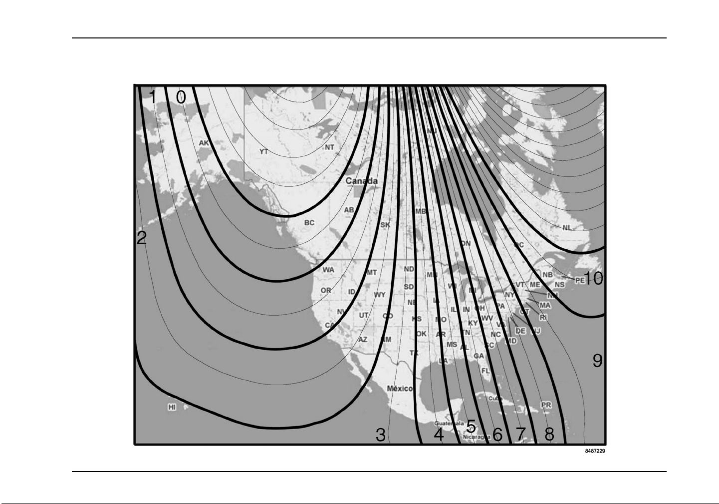
Declination Zone Map
Controls/Features
3879634R1 53
Page 66
Controls/Features
Step Procedure Displayed Message
Select Quadrant 2 (lower r ight) on the display by turning the display control knob either
1
2
3
clockwise or counterclockwise.
Select the Compass Declination message by pressing and releasing the display co ntrol
knob until this message appears.
Press and hold the display control knob until any Declination Zone number (0 – 10) is
displayed.
Turn the display control knob clockwise or counterclockwise until the desired Declination
Zone number is displayed. Refer to Declination Zone Map to determine the proper
number for the current geographic location.
4
5
NOTE: If no Declinat ion Zone number is selected within 15 seconds, the display will return
to the Compass Declination message.
NOTE: If the compass is being calibrated/recalibrated the Declination Zone must be set
to the Zone number for the location where the compass calibration/recalibration is bei ng
performed regardless of the location where the vehicle will eventually operate.
Press and HOLD the display control knob until the C ompass Declination message
appears (this indicates that the new Declination Zone number has been programmed
into the compass).
54 3879634R1
Page 67
Controls/Features
Compass Directional Calibration Procedure
To begin the Compass Directional Calibration Procedure, stop
the vehicle in an area large enough to permit driving in complete
circles and perform the following steps:
Step Procedure Displayed Message
Select Quadrant 2 (lower right) on the instrument panel gauge clu s ter display by turning
1
the display control knob either clockwise or counterclockwise.
Select the Calibrate C
2
3
4
3879634R1 55
knob until this messa
Press and hold the display control knob until the End Calibration command is displayed.
NOTE: IF the End Calibration command wil l not show up, turn OFF the vehicle, restart it,
andreturntoStep1.
NOTE: The following steps (4 through 6) must be completed within 3 minutes to lock-in
the new calibration. Do not press the display control knob or turn the key OFF until
these steps are completed or the calibration process will be cancelled.
Immediately following the End Calibration command being displayed, d rive the vehicle in
3 complete circles (during this time the compass display will go blank or have dashed
lines present).
ompass message by pressing and releasing the display control
ge appears.
Page 68
Controls/Features
Stop the vehicle and wait shortly. The End Calibration message should reappear on
5
6
7
the display.
Push and HOLD the display control knob until the End Calibration command disappears.
The calibration should now be complete. IMPORTANT!: Just pressing and failing
to hold the display control knob inward until the End Calibration command
disappears will cancel the calibration procedure and you must start over at Step 1.
Test the compass calibration. Turn the vehicle ignition key OFF and then restart the
vehicle. Wait 10 seconds to for the compass to complete its self test. Drive the vehicle
in a circle and note the compa ss readings. If the lower left quadrant of the Instrument
Panel Gauge Cluster Display shows the correct compass/vehicle heading, the compass
calibration is now complete. If the compass readings are incorrect, inspect for correct
Declination Zone number, turn OFF the vehicle, restart the vehicle, wait 10 seconds, and
perform another circle while periodically noting the compass readings. If readings are
still incorrect restart the compass calibration procedure.
Integral Digi
Quadrant 1: I
NOTE: The ava
configuratio
tal Display Detailed Information
nformational Displays
ilable display screens are dependant on the
n of the vehicle.
56 3879634R1
Page 69

Controls/Features
Quadrant 1 – Display Messages Description
Odometer The odometer displays the total distance traveled.
Display Format:
100,000.0
MILES
KM
Trip Odometer The trip odometer displays a record of the elapsed distance traveled since the last reset.
NOTE: The trip hours and trip miles are independently reset.
Display Format:
100,000.0
TRIP MILES
TRIP KM
Total Engine Hours The Engine Hour display provides a record of accumulated engine hours, and will not show any increase
unless the engine is running.
NOTE: This display function cannot be reset.
Display Format:
100,000.0
HOURS
Trip Hours The Trip Hour display provides a record of ela psed engine hours since the last reset.
NOTE: The trip hours and trip miles are independently reset.
Display Format:
100,000.0
TRIP HOURS
3879634R1 57
Page 70

Controls/Features
Quadrant 1 – Display Messages Description
Machine PTO A or B Hours This display will provide a record of the total accumulated Machine PTO hours, while PTO function A
or B is engaged.
Display Format:
100,000.0
PTO HOURS A
PTO HOURS B
Machine Trip PTO A or B Hours This d isplay will provide a re c ord of t he total a ccumulated Machine Trip PTO hours, while PTO fu nction A
or B is engaged.
Display Format:
100,000.0
PTO TRP HOURS A
PTO TRP HOURS B
Engine PTO Hours This display will provide a record of the Engine PTO hours sent from engine.
Display Format:
100,000.0
ENG PTO HOURS
Engine PTO Trip Hours This display will provide a record of the Engine PTO Trip hours sent from engine.
Display Format:
100,000.0
ENG PTO TRP HOURS
58 3879634R1
Page 71

Controls/Features
Quadrant 1 – Display Messages Description
Instantaneous Fuel Economy This display provides a record of the instantaneous fuel e conomy sent from the engine.
The display shall be in miles per gallon or lite rs per 100 kilometers, corresponding to the units selected
while in the odometer mode.
Display Format:
30.0
INST MPG
INST L/100KM
Trip Average Fuel Economy The display value shall be the average fuel economy va lue since the last reset of the trip odometer.
The display shall be in miles per gallon or lite rs per 100 kilometers, corresponding to the units selected
while in the odometer mode.
Display Format:
30.0
TRIP MPG
TRIP L/100KM
Machine PTO Fuel Used A and B The display value shall be the calculated Machine PTO Fuel Used.
Display Format:
100,000.0
PTO GAL A
PTO GAL B
PTO L A
PTO L B
3879634R1 59
Page 72

Controls/Features
Quadrant 1 – Display Messages Description
Machine PTO Trip Fuel Used A an d B The display value sh all be the calculated Machine PTO Trip Fuel Us ed.
Display Format:
100,000.0
PTO TRP GAL A
PTO TRP GAL B
PTO TRP L A
PTO TRP L B
Engine PTO Fuel Used The display value shall be the calculated Engine PTO Fuel Used.
Display Format:
100,000.0
ENG PTO GAL
PTO TRP L
Engine PTO Trip Fuel Used The display value shall be the calculated Engine PTO Trip Fuel Used.
Display Format:
100,000.0
ENG PTO TRP GAL
ENG PTO TRP L
Trip Idle Fuel Used The display value shall be the calculated Trip Idle Fuel Used.
Display Format:
100,000.0
TRP IDL GAL
TRP IDL L
60 3879634R1
Page 73
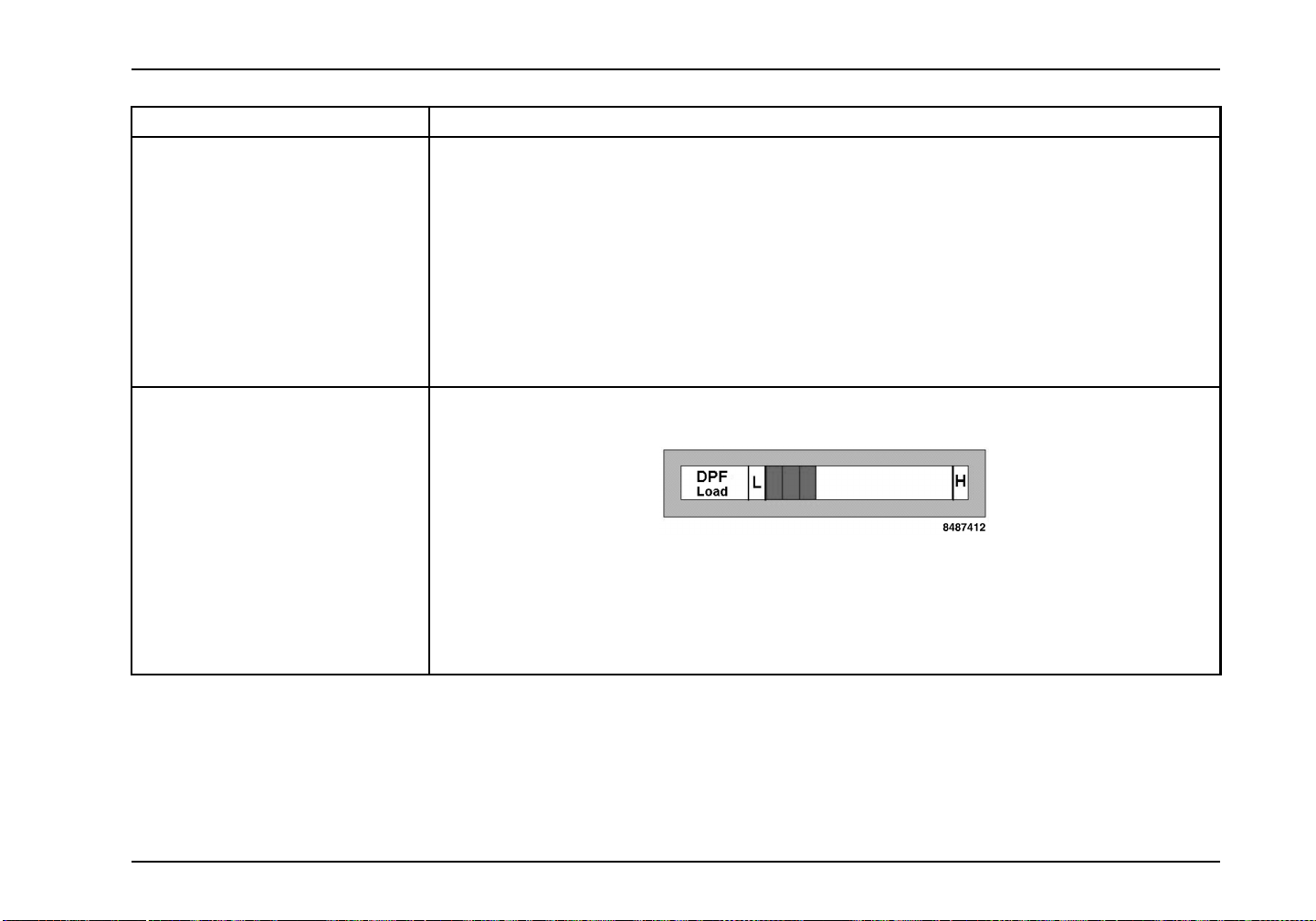
Controls/Features
Quadrant 1 – Display Messages Description
Axle Load Indication The instrument panel gauge cluster shall display an approximate value of Axle Load for the front and/or
rear axles.
NOTE: Axle lo ad readings are most accurate on a level surface with p arking brake released.
Display Format:
approx. 45.0
FT LBSX1000
FT KGX1000
RR LBSX1000
RR KGX1000
Diesel Particulate Filter Level The instrument panel gauge cluster shall display the relative Diesel Particulate Filter (DPF) Level.
The instrument panel gauge cluster displays the following graph:
With “L” (low) on the left and “H” (high) on the right, the graph is shown by bars each representing a 10
percent increase/decrease in soot level.
The instrument panel gauge cluster displays the last received level until a new value is received, or until
the instrument panel gauge cluster detects that it has not received a response to the SPN request, in
which case it shall display the word “data n/a” within the bar graph.
Quadrant 2 Text a
These messages i
message flashes,
be displayed fo
message is view
3879634R1 61
nd Warning Messages
nform the driver of vehicle conditions. If the
it will flash for 3 – 5 seconds, and then will
r an additional 3 – 5 seconds. If more than one
able, the displayed message will be followed by
an asterisk “*”,
messages, press
proceed to the n
The following i
that can be disp
indicating multiple messages. To view additional
and release the Display Control button to
ext m essage.
salistoftheroutine Text and Warningmessages
layed:
Page 74
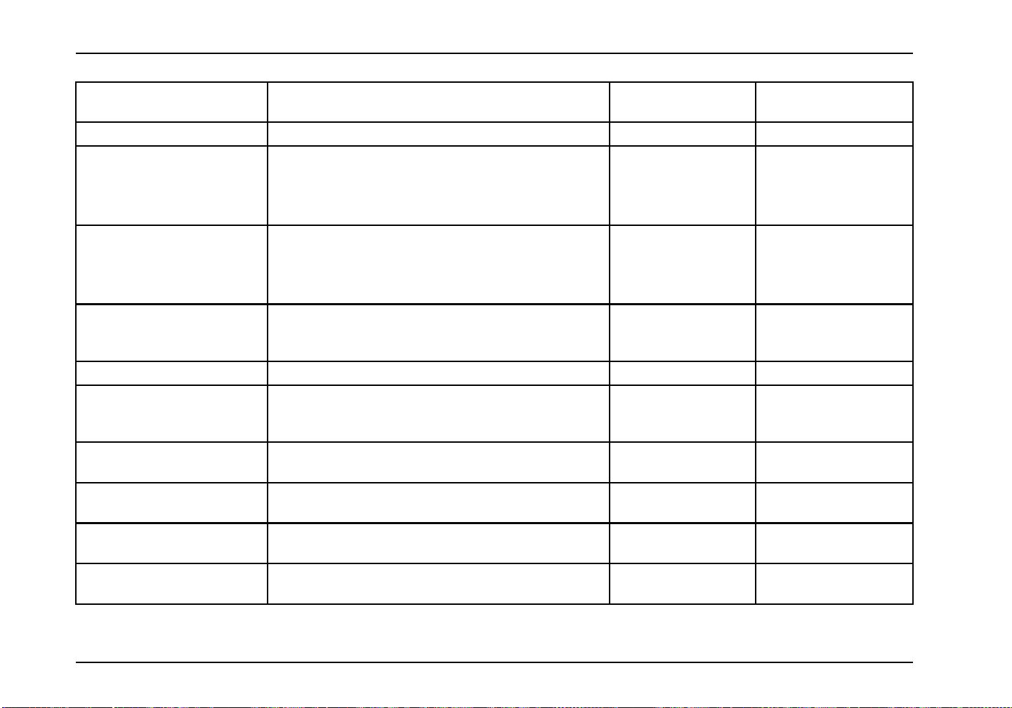
Controls/Features
Quadrant 2 – Display
Messages
PARKD REGEN ACTIVE Message is displayedduringaparkedregeneration. No No
Load Shedding Message is displayed when electrical load control and
Washer Fluid Low Indicates low washer fluid level. Yes No
Electrical Fault When instrument panel gauge cluster’s ability to display
Check A/C Indicates a fault in the HVAC System. Yes No
PARKD REGEN INHIBITED Message is displayed when parked regeneration has been
Air Filter Restriction Message displayed indicates restricted air flow to the
Exterior Lamp Check Active Message displayed indicates Exterior Lamp Check is in
HVAC Temp Setting Bar graph displayed show temperature setting in low to
Activate HVAC Front Blow er Bar graph d isplayed show blower speed setting in Off a nd
Description Flash (Yes/No) Warning Indicator
Association
Yes No
shedding feature is implemented.
Yes No
diagnostic codes is enabled, this message is displayed
when there are active diagnostic codes.
No No
requested, but is not performed due to a veh icle interlock
or an engine fault.
Yes No
engine.
Yes No
progress.
No No
high increments.
No No
low to high increments.
62 3879634R1
Page 75
Controls/Features
Quadrant 2 – Display
Messages
HVAC Sleeper Blower Speed Bar graph d isplayed show blower speed setting in O ff and
Air Pressure Diagnostic Yes No
Cruise Indicates that the Cruise Control System is turned On . No No
Fuel Filter Indicates that the fuel filter is clogged. Yes No
Check Brake Switch Yes No
Check Pupil Warning Indicator Yes No
Check Stop Arm/Crossing Gate Yes No
Check Exterior Lamps Yes No
Engine Control Shutdown Yes No
Check Trailer Lights Yes No
Engine Control System Error Yes No
PARKD REGEN REQUIRED Indicates parked regeneration is necessary. No No
PARKD REGEN INHIBITED
ENG TMP
Description Flash (Yes/No) Warning Indicator
Association
No No
low to high increments.
Message is displayed when engine coolant temperature is
below 170° F (76.6°C).
No No
REGEN INHIBIT SWITCH
ACTIVE
PARKED REGEN AVAILABLE No No
Low Coolant Level Message is displayed when coolant level is less than or
3879634R1 63
Message is displayed when Regen Inhibt Switch is “On”
and regeneration Is disabled.
equal to 80%.
No No
Yes No
Page 76
Controls/Features
Quadrant 2 – Display
Messages
Stop Engine Message is displayed when Red Stop indicator is
Warn Engine (Priority 1 or 2) (1) Message is displayed when MaxxForce, or MaxxForce®
Stop Hybrid Message is displayed when Hybrid system turns on and
Check Engine Message is displayed when ECM requests the Yellow
HV Batt Off-Line Message is displayed when Hybrid system battery is off
Check Hybrid Message is displayed when Hybrid system turns on the
Low Engine Oil Level Message is displayed when engine oil level is less than
Change Engine Oil Message is displayed when engine oil change is detected
Water in Fuel Message is displayed when water in fuel is present. Yes No
Refuel Message is displayed when fuel level is low. MaxxForce®
High Fuel Temp Message is displayed when fuel temp is high. MaxxForce®
Description Flash (Yes/No) Warning Indicator
Association
Yes Red warning indicator
illuminated. MaxxForce® engine o nly.
Yes (1) Red warning indicator
11/13 ECM turn on the Red warning indicator.
(2) Message is displayed when MaxxForce, or MaxxForce®
11/13 ECM requests the Yellow warning indicator and not
the Red warning indicator.
Yes Red warning indicator
requests the Red warning indicator.
Yes Yellow warning indicator
warning indicator and not the Red warning indicator.
Yes No
line.
Yes Yellow warning indicator
Yellow warning indicator while conditions for “HV Batt
Off-Line” message are not met.
Yes No
or equal to 80%.
Yes No
as necessary.
Yes No
11 and 13 engines only.
Yes No
11 and 13 engines only.
(2) Yellow warning
indicator
64 3879634R1
Page 77
Controls/Features
Quadrant 2 – Display
Messages
Electrical Fault (Priority 1 or 2) (1) Message is displayed when EGC requests the Red
Check Trans Message is displayed when transmission needs to be
Trans Temp Message is displayed when transmission turns on
Gen Trns Flt Message is displayed when transmission turns on Red
Trans Oil Life Message is displayed when transmission oi l needs
Trans Oil Filter Message is displayed when transmission oil filter needs
Trans Service Message is displayed when transmission needs service.
DPF Ash Service Required Message is displayed when diesel particulate filter ash
See Visor For Info Message is displayed indicates the particulate trap
Description Flash (Yes/No) Warning Indicator
warning indicator.
(2) Message is displayed when EGC requests the Yellow
warning indicator.
serviced.
the Yellow warning indicator. Not available with all
transmissions.
Stop, MIL, or PROTECT, or the Yellow Warning indicator
without the condition s to display Check Trans, Trans Temp,
Trans Oil Life, Trans Oil Filter, or Trans Service. Not
available with all transmissions.
changed. Not available with all transmissions.
changed. Not available with all transmissions.
Not available with all transmissions.
level requires service/cleaning.
indicator must be on or must flash.
Association
Yes (1) Red warning indicator
(2) Yellow warning
indicator
Yes Yellow warning indicator
Yes Yellow warning indicator
Yes Yes (see description)
Yes No
Yes No
Yes No
Yes No
Yes Yes (see description)
3879634R1 65
Page 78
Controls/Features
Quadrant 2 – Display
Messages
ECM, TCM, Shift Selector,ABS,
Retarder – Driveline, EGC,
Compass Module, ESC, VSM,
SD, AGSP, TPMS, Exhaust
Module, Telematics, AGSP 2,
SIC2,AGSP3,SIC1,PAM,
Hybrid, Service Tool, Global
ECM, TCM, Shift Selector,ABS,
Retarder – Driveline, EGC,
Compass Module, ESC, VSM,
SD, AGSP, TPMS, Exhaust
Module, Telematics, AGSP 2,
SIC2,AGSP3,SIC1,PAM,
Hybrid, Service Tool, Global
Retarder Temp Message is displayed when instrumen t panel gauge cluster
Gen Rtrd Flt Message is displayed when instrument panel gauge cluster
DRV Reward Expected No No
DRV Reward Good No No
DRV Reward Excellent No No
DRV Reward Penalty No No
Description Flash (Yes/No) Warning Indicator
Association
Message is displayed when a module other than the
engine requests the red stop warning indicator.
Message is displayed when a module other than the
engine requests the Yellow warning indicator.
receives signal from the Retarder – Driveline requesting
the Yellow warning indicator.
receives signal from the Retarder – Driveline requesting
the Red warning, MIL, or PROTECT indicator, or the
Yellow warning indicator without the conditions to display
Retarder Temp..
Yes Red warning indicator
Yes Yellow warning indicator
Yes Yellow warning indicator
Yes Yes (see description)
66 3879634R1
Page 79
Controls/Features
Quadrant 2 – Display
Messages
DRV Reward Increasing No No
DRV Reward Decreasing No No
VSL Ovrd Active No No
VSL Ovrd Expiring No No
Calibrate Compass Message is displayed when vehicle speed is less than
End Calibration Message is displayed when vehicle speed is less than 2
Calibration Ended Message is displayed when vehicle speed is less than 2
Declination Zone Message is displayed only when vehicle speed is less than
Description Flash (Yes/No) Warning Indicator
Association
Blank screen, available only when engine rpm less than
or equal t o 325 RPM, or vehicle speed less than 2 mph
(3 km/h).
2 mph (3 km/h) and the operator has not requested
“Calibrate Compass” in the current ignition cycle.
mph (3 km/h) and the operator has requested “Calibrate
Compass” in the current ignition cycle.
mph (3 km/h) and the operator has requested “Calibrate
Compass” in the current ignition cycle.
2 mph (3 km/h).
No No
No No
No No
No No
No No
Warning Messages
In addition to the Diagnostic Trouble Codes (DTC), the digital
display will display a warning message whenever an Engine
indicator is illuminated. This warning messa ge will be toggled
Red Stop indicator: Stop Engine me ssa g e
The following chart provides the warning messages that are
displayed along with corresponding Instrument panel gauge
cluster indicators.
with the normal DTC as follows:
Yellow Warning indicator: WARN ENGINE message
3879634R1 67
Page 80
Controls/Features
MaxxForce® Engines
Warning indicator Warning Message
Red Stop Stop Engine
Yellow Warning Warn Engine
Quadrant 3: Display Messages
Outside Temperature and Compass Displays (Optional)
The optional Outside Temperature and Compass Heading is
displayed in Quadrant 3. Typical displays for Temperature and
Compass Heading are listed in the following table. The display
provides both the outside ambient temperature and the relative
direction of the vehicle within a particular geographical zone.
Vehicle must be moving to acquire an accurate temperature.
Quadrant 3 –
Display Messages
Outside
Tempera t ure and
Compass Heading
Description
Display Format:
Outside Temperature Reading
The Outside Temperature is displayed on the first line of
Quadrant 3 above the Compass Heading. The temperature
sensor is located near the front bumper. Due to its location,
the sensor readings can be affected by road or engine heat
during idling or prevailing driving conditio ns (extended slow
movement).
The display will be in °F or °C, depending on the units selected
while in the odometer mode.
Quadrant 4: Transmission Gear Displays
Quadrant 4 – Transmission Gear Indications
Allison P-R-N-D-L gear
display
Eaton® Transmission display
68 3879634R1
Page 81
Controls/Features
Steering Wheel Controls
The steering wheel contains the Electric (city) horn, Optional Air
horn co ntrol, and Cruise/Throttle controls.
1 AIRHORN-Use
horn.
2 HORN - Used to activate the city horn.
dtoactivatetheair
3 CRUISE/THROTTLE - ON/OFF - Turns
the speed control feature ON or OFF.
Engine speed does not change when
you press the ON position. This control
just activates/deactivates the feature.
When the OFF position is pressed, th e
system will be turned OFF.
4 RESUME/ACCEL - Used to resume the
desired speed set on the cruise control
or accelerate to a higher desired speed.
When parked, used to increase idle
RPM.
Cruise Control
The cruise control systems for all electronic engines function in
a very similar manner. The biggest difference is the minimum
and maximum allowablecruise control speeds that will vary from
vehicle to vehicle.
WARNING
Do not use the cruise control system when
unpredictable driving conditions are present.
Such conditions include heavy traffic, roads
that are winding, icy, snow covered, slippery,
or with a loose surface. These conditions may
cause wheel slippage and loss of vehicle control,
resulting in property damage, personal injury, or
death.
3879634R1 69
Page 82

Controls/Features
Basic Fun ctions of Steering Wheel Controls
The CRUISE/THROTTLE - ON/OFF control turns the
speed control feature ON or OFF. Engine speed does not
change when you press the ON position. This control just
activates/deactivates the feature. When the OFF position is
pressed, the system will be turned OFF.
The left side CRUISE/THROTTLE switch has different labels,
depending on which feature was ordered. However, they all
perform the same function: to turn ON the basic feature.
The two available options are:
• Throttle - used when only throttle or an engine speed control
is ordered;
• Cruise/Throttle - used when cruise control and either a hand
throttle or an engine speed control are ordered.
The right switch (SET/COAST - RESUME/ACCEL) actually sets
and controls the enginespeed. But if the left switch has not been
activated, nothing will happen when pushing on this right switch.
This switch has the same label in all applications.
Operational Procedures
The following steps will activate and enable each of the four
engine speed control features.
Cruise Control – operates like an automotive cruise control.
1. Press the ON position of the CRUISE/THROTTLE -
ON/OFF steering wheel control.
2. Bring the vehicle to the desired operating speed ( above
35 MPH), and then push the SET/CRUISE position of
the steering wheel control.
3. Once in the cruise mode the right side SET/CRUISE
– RESUME/ACCEL switch can be used to increase or
decrease vehicle speed by pressing and holding the
RESUME/ACCEL to increase or the SET/CRUISE to
decrease vehicle speed.
4. A slight tap on the brake or clutch pedal will deactivate
the cruise but holds the selected speed in memory. To
return to this speed, just press RESUME/ACCEL.
5.WhenyoupresstheOFF(left)positionofthe
CRUISE/THROTTLE - ON/OFF switch, or if the vehicle
is shut off, the selected speed setting is canceled.
Throttle
This feature is ordered to provide variable engine speed control
primarily for operation of PTO powered equipment. It uses the
same Cruise controls as described below.
1. Press the CRUISE/THROTTLE - ON/OFF steering
wheel control to ON.
2. Press SET/CRUISE on the steering wheel control.
3. Press and hold RESUME/ACCEL to increase engine
speed until the desired engine speed is obtained. Or,
youcan re peatedlypress and release RESUME/ACCEL
to increase the speed in small increments.
70 3879634R1
Page 83

Controls/Features
4. To change from this initial setting, use the appropriate
control to raise or lower the engine speed as you would
in the cruise control mode. SET/CRUISE reduces
engine speed and RESUME/ACCEL increases engine
speed.
5. Press the OFF position of the ON/OFF control to turn
the throttle off and return the engine to idle.
Stationary Variable Speed Control (12VXT)
This feature is ordered to provide variable engine speed c ontrol
primarily for operation of PTO powered equipment. It operates
the same as the Cruise/ Throttle controls discussed above.
Stationary Pre-Set Speed Control (12VXU)
1. To activate this feature, press the ON position on the left
side CRUISE/THROTTLE - ON/OFF switch.
2. When ordered, this feature can provide two different
predetermined speeds, which are selected with the
SET/CRUISE or RESUME/ACCEL positions. You need
toknow which positionto use for your specific operation.
Press the right side SET/CRUISE or RESUME/ACCEL
switch for the desired pre-set speed.
3. First, press the switch that selects one of the desired
speeds.
4. To select the other speed, press the other switch. The
engine will immediately return to idle.
5. Youmustpushtheswitchasecondtimetogotothe
second speed. This is done to protect equipment from
being inadvertently operated at the wrong speed.
Mobile Variable Speed Control (12VXV)
Operates the same as cruise control, except the engine speed is
accurately controlled instead of vehicle speed. The truck could
be operated in one of several gears but the truck is limited to
a maximum of 20 MPH, or any pre-set lower speed down to 3
MPH.
3879634R1 71
Page 84

Controls/Features
Steering Column and Switches
The steering column contains switches and levers to aid in the
comfort of the operator and to assist the operator while driving
the vehicle.
1. Washer/Wiper Control - The windshield washer, along with
the windshield wipers, is controlled by the WASHER/WIPER
knob on the turn signal switch lever. To operate the windshield
washer, push in on the wiper knob to spray solution on the
windshield. Wipers will start wiping and continue for two cycles.
2. SignalingForA Turn- Whensignalingyourintentiontomake
a turn, move the turn signal lever up or down to the “full turn”
position which is past the point of resistance. On some models
the switch will automa ticallycancel if the steering whee l is turned
a large enough degree. On other models the switch does not
automatically cancel and will require manual cancellation.
Lane Change – The turn signal lever includes a “lane change”
feature which allows the operator to signal the intention to
change lanes without locking the switch into the full turn
position. To use this feature, move turn signal lever up or down
to the point where resistance to movement is felt. The turn
signal lever will return to the OFF position when released.
3. Windshield Wiper - The electric wiper has two speeds
(hi-low),whichcanbeoperatedbyrotatingtheWASHER/WIPER
knob. The optional intermittent control provides five wiper
ON/OFF cycle intervals, varying from 2 to 14 seconds. This is
done by rotating the w iper control from the wiper OFF position
to the any of the five intermittent wiper interval positions.
Automatic Intermittent Interval Control (Optional) –This
feature automatically changes the wiper speed from HIGH or
LOW to the slowest intermittent speed when the parking brake
has been set, and the wipers have been on for a predetermined
length of time. When the parking brake is released, the wipers
return to their previous speed.
Multi-function Switch - The multi-function turn signal switch
is mounted on the left side of the steering column below the
steering wheel.
72 3879634R1
Page 85

Controls/Features
WARNING
Do not use the washers in freezing weather
without first warming the windshield with the
defrosters; otherwise, the washer solution may
freeze on the windshield and obscure your vision
and cause an accident which could result in
property damage, personal injury, or death.
Do not use radiator coolant or anti-freeze in the
windshield washer reservoir. Radiator coolant
in the washer reservoir can severely reduce
visibility when sprayed on the windshield.
Keep the fluid reservoir filled with Fleetrite® Windshield Washer
Solvent or equivalent.
4. Low/High Beam - When the turn signal stalk is pulled past
the “click” position, lights will switch to Hi-Beam position. When
pulled again they will revert to Lo-Beam .
Headlight Flash-To-Pass - When the turn signal lever is pulled
withtheheadlightsOFF,theHi-Beamlightswillcomeonandstay
on as long as the lever is held in the pulled position. When the
Lo-Beam headlights are ON, the Hi-Beam lights can be made to
flash if the lever is not lifted past the ”click” or dimmer position.
5. Hazard Warning Switch - Red rocker switch located above
multipurposeturn signal lever. Push switch to forward position to
activate. The hazard warning flasher will operate with the ignition
switch in the ON or OFF position. Use the warning system any
time your vehicle becomes a traffic hazard, day or night. Push
switch rearward to deactivate.
Stop Override Hazard (Optional) - When hazard lights are
activated and the brake pedal is depressed, all hazard/turn
signal lights on the front, side lights of the truck, and the side
trailer lights will continue to flash. The rear lights of the truck or
tractor will burn steadily until the brake is released.
6. Tilting Adjustment Lever (Optional) - Allows the steering
wheel placement to be adjusted for driver comfort. Pull up to
adjust, push down to lock.
7. Trailer Brake Lever - This lever is used to apply and release
thebrakestothetrailer.
3879634R1 73
Page 86

Controls/Features
Center Dash Panel/Wing Panel
The Center Control Switch Panel consists of the switches
that start the vehicle, control the vehicle’s normal operations,
vehicle lights, and special mechanical functions. The panel also
includes control of the interior comfort levels (HVAC controls),
optional parking brake controls and auxiliary electrical power
source (see Vehicle Operation for operational details). Refer
to the Radio Operator’s Manual provided with the vehicle for
instructions on operating the radio installed in this Vehicle.
1. Radio
2. Fan Speed Control
3. Temperature Control
4. Mode Control
5. Storage Compartment/Optional Switch Pack Location
6. Parking Brake
7. Optional Component Panel
8. Trailer Air Supply
9. Optional Switch Pack Location
10. Ignition Switch
11. Switch Pack
74 3879634R1
Page 87
Switches
Up to 25 optionalswitches can be locatedin the centerand lower
right side of the center dash panel. Location of these switches
will vary depending on the options installed. Blank cover plates
willbeused in spacesthatdo not haveswitchesinstalled at those
locations.
Item Description
Marker Interrupt – MKR INTR
Controls/Features
Transmission Retarder – RTARDR ON
Turns ON transmission retarder to slow down drivetrain.
Transmission Retarder – HI/LOW
Selects the percentage of Transmission Retarder
capability. HI = 66%; LOW = 33%.
A momentary switch that turns all trailer marker lights
ON or OFF, depending on park li ght switch position.
Heated Mirror – ON/OFF
A momentary switch that, when pushed and released,
turns the mirror heating element ON or OFF.
ENG BRAKE – ON/OFF
Turns engine compression brake ON/OFF.
ENG BRAKE 1/2/3
A three position switch that selects the amount of
engine braking (1 = Low, 2 = Medium. 3 = High)
FOG LIGHT – ON/OFF
Turns ON Fog Lights when the switch is in the ON
position, i gnition switch is in the “Ignition” or “Start”
position, and the headlights are ON and in low beam
mode.
TRAC ENAB/DISAB
This switch enables or disables the ABS traction feature.
OFF ROAD ENABL
As part of the a
switch, when e
and more whee
E
utomatic traction control system, this
nabled, allows for greater engine power
l spin on soft road surfaces.
3879634R1 75
Page 88
Controls/Features
MUD/SNOW ENABLE
As part of the automatic traction control system, this
switch, when enabled, allows for greater engine power
and more wheel spin on soft road surface s.
PLOW LIGHT ON/OFF
With this feature, the ON position selects the high
mounted Plow lights whenever the headlights are ON. If
the operator shuts OFF t he vehicle with the plow lights
ON, they will remain ON.
LIFT GATE – ON
This switch provides power to the lift gate system.
This optional feature provides battery protection and/or
programmable time out.
AUTO NEUTL – ON
When the ON position is selected and the parking
brake is applied (vehicle speed is near zero mph), the
transmission goes into (auto) neutral.
FANOVRD–ON
With the switch in the ON position, the fan mode is
switched from “auto” to the constant “on”.
The switch indicator will be ON when the ON position
is selected.
WORK LIGHT – ON
This switch is used to turn the back of cab work light
ON or OFF.
2SpeedAxle–2SPDLO/2SPDHI
A 2 speed switch that allows the operator to select
either high o r low rear axle ratio.
Power Divider lock – LOCK/PDL
This switch is used to lock together the front and rear
axle of a tandem.
SUSP/DUMP
This switch allows the operator to release the air from
or reinflate the air bags of the air suspension system.
PTO OFF/ON
Engages Power Take Off when switch is in ON position
or disengages Power Take Off when switch is in PTO
OFF position.
5TH WHEEL SLIDE ON/OFF
This switch, when set to ON, releases the sliding 5th
wheel (when ignition switch is in “Run” and vehicle
speed is less than 2 mph).
Differential Lock – DIFF/LOCK
This switch, when set to LOCK, engages the locking
differential which locks the right and left side tires (only if
vehicle is below maximum differential lock engagement
speedof25mph(40km).
76 3879634R1
Page 89
Controls/Features
Forward Rear Tandem Axle Differential Lock – DIF FR
AXLE LOCK
This switch, when set to LOCK, engages the forward
rear locking differential for improved traction on poor
surfaces (only if vehicle is below maximum differential
lock engagement speed of 25 mph (40 km).
Rear Rear Tandem Axle Differential Lock – DIF RR
AXLE LOCK
This switch, when set to LOCK, engages the rear
rear locking differential for improved traction on poor
surfaces (only if vehicle is below maximum differential
lock engagement speed of 25 mph (40 km).
Front Axle Differential Lock – FRONT AXLE/ON
Engages Front Axle for 4X4 operation.
Transfer Case – XFER HI/XFER LOW
Selects Transfer Case high or low gear ratio.
AIR ASSIST – (OFF) ON
Provides inflation or deflation of auxiliary air bag.
Engine Shutdown Override – ENG OVRD/ON
This momentary switch, when pushed to the ON
position, will allow the vehicle to be restarted in the
event of an automatic engine shutdown.
AC Power Enable – ON 120V AC
This switch, when set to the ON position, will provide
AC output from the Power Pack 3 inverter.
WINTER/ENGINE INTAKE
Used to change engine intake air from “outside air” to
engine compartment air.
PARKD REGEN – ON
DPF regeneration activation when parked switch is
used for engine after-treatment. Manually initiates DPF
regeneration.
INHIBT REGEN – ON
The Regeneration Inhibit switch is used to prevent
the Active Regeneration or Parked Regeneration
processes.
ENAB/DATA LOG
When enabled, allows the driver to log the last five
seconds of data group’s operational parameter values
into ECM memory.
3879634R1 77
Page 90
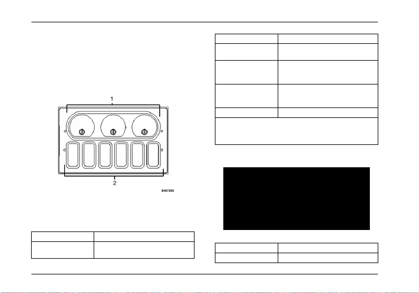
Controls/Features
Auxiliary Gauge/Switch Package (AGSP)
(Optional)
The Auxiliary Gauge/Switch Package provides locatio ns for
three additional gauges and six switches for optional customer
requirements. The following lists the gauges that are approved
for this location.
Optional Gauge Function
Ammeter Gauge Provides reading of batteryandalternator
current in Amps.
Rear–rear Axle
Temperature Gauge
Front–rear Axle
Temperature Gauge
Load Indicating Gauge Provides reading of rear axle lo ad. *
* Gauge reading is for reference only. DO NOT base legal
loading criteria on this gauge reading.
Refer to Switches in this section for optional auxiliary switches.
Provides monitoring of temperature of
axle lubri cant. Warning indication at
230°F.
Provides monitoring of temperature of
axle lubri cant. Warning indication at
230°F.
Panel Component Arrangements (Optional)
1. Auxiliary
2. Auxiliary
Optional Gauge Function
Air Application Gauge Provides readings of brake application
Gauge Locations
Switch Locations
air pressure. Max pressure of 150 psi.
Item Component Description
1 Two Post Power Socket
78 3879634R1
Page 91
Controls/Features
Item Component Description
2 Cigar Type Power Socket
3 Optional Filter Minder
4 Three Switch Pack
a. Optional Winter/Engine Intake
Switch
b. Optional Air Horn Switch
c. Optional Ether Start Swi tch
d. Optional Engine Start Switch
e. Optional Axle Enable Switch
f. Optional Axle Up/Down Switch
g. Optional Roof Auxiliary Switch
Item Component Description
5 Telematics No Data Logged Switch
6 Telematics Driver Alert Switch
7 Cigar Lighter
3879634R1 79
Page 92
Controls/Features
Climate Control
WARNING
Never drive the vehicle unless the windshield and all other windows are clear. A fogged, ice/snow covered, or dirty windshield
or window limits vision, which could cause an accident, resulting in property damage, personal injury, or death. To improve
defroster efficiency, remove ice and/or snow by hand from the windshield and windows with a non-metallic scraper.
CAUTION
Toclear system of humid air, operate blowers for 30 seconds at high speed, with the AIR FLOW/AIR CONDITIONER knob on the
normal heating position be f ore selecting the DEF position. This will prevent fogging the glass, which can occur if humid air is
blown onto a cool win dshield.
NOTE: The vehicle may be equipped with optional heater shut off va lve(s) to prevent hot coolant from circulating through the heater cor e(s). Clo sing
the valve(s) during hot weatheroperationwill improve A/C system performance. If the valves are shut off, in-cab temperature adjustment may become
limited. In addition, when shut off valves are closed, defrosters will only produce cold air.
Item No. Item Description
36 Fan Speed Control Use this control to regul ate the amount of air provided to the vents in any mode you select. Turn
theknobclockwisetoincreasefanspeed.TurningthecontroltotheOFFpositionwillshutOFF
the fan (and the A/C compressor if A/C is selected), but does not prevent outside air from entering
the vehicle. On vehicles equipp ed with A/C, moving the mode knob to the MAX A/C position, with
the fan ON, will close the fresh air door eliminating outside air from entering the vehicle.
37 Temperature Control Use this control to regulate the temperature of the air discha r ged from the vents. The blue area of
the control indicates cooler temperatures, while the red area indicates warmer temperatures.
38 Mode Control NOTE: The dot between the mode control icons is an additional mix position between the two
modes.
Use this control to direct the flow of air as follows:
80 3879634R1
Page 93
Controls/Features
MAX Air Conditioning Mode
In this mode, all airflow is directed to the panel air outlets and the air is recirculated inside the
vehicle. Use this mode to block out any outside odors, smoke, or dust and to cool the interior
rapidly upon initial start up in very hot or humid weather.
NOTE: Continuous use of the recirculation mode may make the inside air stuffy. Use of this mode
for longer than fifteen minutes without a window slightly open is not recommended.
The A/C compressor turns ON and OFF automatically as needed when in this mode.
NORM Air Conditioning Mode
In this mode, all airflow is directed to the panel air outlets. Fresh (outside) air is used to cool the
vehicle in this mode.
The A/C compressor turns ON and OFFautomatically as needed when in this mode.
Bi-Level Air Conditi
In this mode 75 percen
airflow is directed t
The A/C compressor tu
Vent Mode
In this mode, all airflow is directed to the panel air outlets, and fresh (outside) air is circulated
inside the vehicle.
Floor Mode
In this mode, all airflow i s directed to the floor air outlets, and fresh (outside) air is circulated
inside the vehicle.
3879634R1 81
oning Mode
t of the airflow is directed to the panel air outlets and 25 percent of the
othefloor air outlets, and fresh (outside) air is circulated inside the vehicle.
rns ON and OFF automatically as needed when in this mode.
Page 94
Controls/Features
Mix Mode
In this mode 50 percent of the airflow is directed to the defrost and side demist air outlets and
50 percent of the airflow is directed to the floor air outlets, and fresh (outside) air is circulated
inside the vehicle.
The A/C compressor turns ON and OFF automatically as needed when in this mode to reduce
humidity levels and help reduce moisture buildup on the windshield.
Defrost
In this mode, all of the airflow is directed to the defrost and side demist air outlets, and fresh
(outside) air is circulated inside the vehicle.
The A/C compressor turns ON and OFF automatically as needed when in this mode to reduce
humidity levels and help reduce moisture buildup on the windshield.
To remove stale air or smoke while air conditioner is operating, you may want to o pen a vent window for a short perio d of time. Always park in
the shade when possible. If your vehicle has been parked in the sun with the windows up, remove the overheated air inside by driving with
windows down and the air conditioner ON for one or two city blocks.
Air Conditioning
keeps all the mechanical parts of your air conditioner in good
operating condition.
CAUTION
Failure to follow recommended service
procedures and maintain adequate air flow
through air exchange devices may result
in component failure. Cleaning should be
performed by a qualified technician.
Keep radiator area free of bugs, leaves, etc. Do not cover the
condenser with a wire screen.
It is normal for small amounts of water to drain out of the air
conditioner module. This water is condensed moisture removed
from the air inside the vehicle.
Correct airflow may be restored by either replacing the filter(s),
which can be done without tools, or by cleaning the filters. The
filter(s) may be cleaned by using a power washer with a soap
solution. Keep the spray head at least six inches away from the
filter to avoid damage. Rinse thoroughly.
At least once or twice a month, turn ON the air conditioner for a
few minutes while the engine is running. This periodic operation
82 3879634R1
Page 95

Controls/Features
NOTE: If your air conditioning performance seems lower
than expected, check the front of the A/C condenser for an
accumulation of dirt or insects. Clean with a gentle water spray
from behind the radiator and through the condenser as required.
Check for dirt and debris in both the cab and sleeper HVAC
intake filters that may reduce airflow.
NOTE: The air conditioning system incorporates a low-pre ssure
switch, w hich disengages the compressor clutch if evaporator
outlet pressure falls below a certain set point. To restart the air
conditioning system after an automatic shutdown has occurred,
the operator must do one of the following:
1. Set A/C control to OFF and then back to ON. Fan speed
control knob MUST NOT be in the OFF position.
2. Place fan speed control knob in OFF position and then
back to the desired speed setting. A/C system must be
ON.
NOTE: If the syst em continues to shut down automatically, have
the system checked.
NOTE: The vehicle may be equipped with optional Heater Shut
Off Valve(s) to prevent hot coolant from circulating through the
heatercore(s). Closingthevalve(s)during hot weather operation
willimproveA/Csystemperformance. IfthevalvesareshutOFF,
in-cab temperature adjustment may become limited. In addition,
when shut off valves are closed defrosters will only produce cold
air.
Dehumidification
The heater/defroster systems can be oper ated simultaneously
with the air conditioner during mild weather and h igh humidity
conditions to dehumidify the cab air. Turn the mode button to
one of the A/C positions and position the temperature knob at
a comfortable temperature location. The air conditioner will
removethe humidity while the heaterkeeps the cab comfortable.
Door and Window Controls
Door Lock/Unlock
Cab Doors a nd Locks
The cab doors can be unlocked with the same key used for the
ignition lock. There is also a keyless remote entry available.
NOTE: The vehicle is delivered with two identical keys. If
more keys are needed, order them through your authorized
International dealer. Record the key code and keep it in a
secure place. A new key can be made if the keys are lost.
3879634R1 83
Page 96

Controls/Features
1. Door Handle
2. Key Lock
3. Interior Lock
4. Interior Door Handle
To open any door from inside,
pull out on interior door
handle.
To open any door from
outside, grab door handle
and pull downward.
With mechanical locks, only one door can be locked/unlocked at
a time. Electrical locks can lock/unlock both doors by operating
either the key, keyless entry fob, or the inner door lock handle
on either side.
If equipped with a crew cab, the rear door locks, when engaged,
must be unlocked using the mechanical lock release or the
switch for electric locks. The rear interior door handle will not
disengage the door locks.
Remote Keyless E ntry Operation (Optional)
The remote keyless entry key fob is used to lock and unlock all
doors from a distance of 30 feet (9 m) or less. Whenever the
doors are locked or unlocked using the key fob, the city horn
soundsmomentarily (chirps). Also, the remote keyless entry key
fob turns ON the interior light for a time period when the Unlock
button is pressed, and turns OFF the light (dims gradually to
OFF) when the Lock button is pressed. The Panic (emergency)
button, when pushed, causes the horn to chirp ON/OFF for three
minutes in unison with the headlights and park lights flashing.
This feature works only when the ignition switch is in the OFF
position.
The auxiliary button will be used to toggle the optional work light
ON or OF F (if OFF,itwillbe turned ON, and if ON, itwill be turned
OFF).
84 3879634R1
Page 97
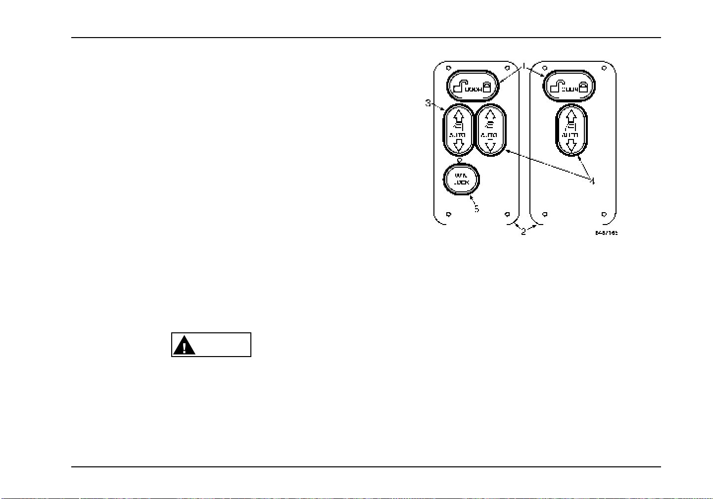
NOTE: This device complies with Part 15 of the FCC Rules and
with RSS-210 of Industry Canada. Operation is subject to the
following two conditions:
1. This device may not cause harmful interference.
2. This device must accept any interference received,
including interference that may cause undesirable
operation.
Changes or modifications not expressly approved by the party
responsible for compliance could void the user’s authority to
operate the equipment.
Door Opening/Unlock
Enter or exit the vehicle by manually pulling on the exterior
or interior door handles. To open the door from the interior, if
locked, the front door will unlock when the door handle is pulled.
If equipped with a crew cab, the rear door locks, when engaged,
must be unlocked using the mechanical lock release.
Lock/Unlock from Interior
Controls/Features
1. Lock/Unlock Button
2. Door Control Panel
3. Driver Side Power Window Control
4. Passenger Side Power Window Control
WARNING
To help reduce the risk of personal injury in the
event of an accident, keep doors locked when
vehicle is in motion.
3879634R1 85
5. Window Lock Control
Locking the Door
To lock, push the lock/unlock button on the lock symbol in the
door control panel located by the vent window. Pressing the
lock/unlock buttonon the lock symb ol once locks both cab doors.
Page 98

Controls/Features
Unlocking the Door
To unlock, push the lock/unlock button on the unlock symbol in
the door control panel located by the vent window. Pressing the
lock/unlock button once on the unlock symbol unlocks the driver
door. Pressing it twice unlocks both doors.
Automatic Door Lock Function
The automatic lock function automatically locks the doors at a
predetermined speed.
Windows
Manual Operation
To lower door glass (driver door), turn window regulator handle
clockwise. To raise glass, turn handle counterclockwise.
Reverse this procedure for the passenger door.
Power Operation
Trucks may have optional electrically-operated driver and
passenger windows. Controls for these window lifts are
mounted in the door control panels located by the vent windows.
The driver s ide controls regulate window operation for both
driver and passenger. To lower or raise driver window, press
andholdeither“Up”or“Down”directiononthedriversideAUTO
window control. To lower or raise passenger window, press
and hold either “Up” or “Down” direction on the passenger side
AUTO window control.
For one-touch windows down operation, press and release the
window control in the “Down” direction. The window will then go
to the full down position automatically.
Window Lockout Function
The drive r also has the ability to prevent passenger window
up/down operation by pressing the WINDOW LOCK control.
Mirror Controls
1. Mirror Select Switch
2. Mirror Direction Control Switch
86 3879634R1
Page 99

Controls/Features
These controls provide the driver with the ability to operate both
driver- and passenger-side flat mirrors. Use the mirror select
switch to select which mirror is to be adjusted and adjust the
mirror using the mirror direction control switch.
Vent Window
Vehiclesareequippedwitheitherafixedoropeningventwindow.
The opening vent window can be opened and closed to allow
additional airflow into the cab.
Driver Reward
The driver reward feature is designed to give the operator
incentives for driving more efficiently. This is accomplished by
measuring the driver’s habits based on fuel economy, time at
idle, or both. Rewards include higher maximum vehicle speed
and higher cruise control speed limit. Lower maximum vehicle
speed or cruise control speed limits may result as a penalty for
failing to meet the standards.
The following driver reward visual indications appear in the form
of text messages in the gauge cluster digital display:
• Expected –Reward indication which results in highervehicle
speed limits.
• Good – Reward indication which results in higher veh icle
speed limits.
• E xcellent – Reward indication whic h results in higher vehicle
speed limits.
• Penalty – Penalty indication which results in lower vehicle
speed limits.
• In creasing – Informs the driver that the vehicle speed limit
will soon be increased.
• Decreasing – Informs the driver that the vehicle speed limit
will soon be decreased.
3879634R1 87
Page 100

Controls/Features
88 3879634R1
 Loading...