

Page 1

Read Operators Manual For SafetyPARTS MANUAL
Copyright © 2007 Terramite Corporation
WWW.TERRAMITE.COM
Charleston, WV/USA
USA 1.800.428.3772
Intl. 1 .304.776.4231
Page 2

Read Operators Manual For Safety PARTS MANUAL
Copyright © 2007 Terramite Corporation
Table of Contents
SECTION ONE: INTRODUCTION/INFORMATION
History of Terramite Backhoes .................................................................................. 1.1
Before You Start ......................................................................................................... 1.2
Safety Tips .................................................................................................................. 1.2
Hand Signals .............................................................................................................. 1.3
Call First ..................................................................................................................... 1.4
SECTION TWO: PARTS
Left or Right is Determined from the Operator’s Position ...................................... 2.1
View of Front Loader Bucket .................................................................................... 2.2
View of Right Side of Loader Bucket ....................................................................... 2.3
View of Underside of Arm Center.............................................................................. 2.4
View of Right Side of Arm Assembly ...................................................................... 2.5
View of Front Axle
View of Front Axle
(Bumper Not Shown) ................................................................................. 2.6
(continued) ................................................................................................ 2.7
View of Front Axle - Ball Socket Style (Bumper Not Shown) ............................................ 2.8
View of Hub Assembly and Spindle ......................................................................... 2.9
View of Right Front Tire and Rim .......................................................................... 2.10
View of Right Side of Tractor ................................................................................. 2.11
View of Left Side of Tractor .................................................................................... 2.12
View form Right Side of Diesel Engine Compartment
(Without Air Filter) ................ 2.13
View of Diesel Air Filter Assembly ........................................................................ 2.14
View of Muffler Assembly - Diesel ......................................................................... 2.15
View Left Side of Kubota Engine............................................................................ 2.16
View Right Side of Kohler Engine ......................................................................... 2.17
View of Kohler Engine Leftside .............................................................................. 2.18
View of Power Steering Gear ................................................................................... 2.19
View of Front Valve w/Fittings .............................................................................. 2.20
View of Loader Valve Assembly and Battery - Perkins ......................................... 2.21
View of Front Valve Linkage System .................................................................... 2.22
View of Left Side of Diesel Dash Wiring Harness - Perkins ................................. 2.23
View of Right Side of Diesel Dash Wiring Harness -Perkins ............................... 2.24
View of Operator Position Facing Dash (Diesel) ................................................... 2.25
View of Operator Position Facing Dash (Gas) ....................................................... 2.26
View of Transmission Assembly (Diesel) .............................................................. 2.27
View of Transmission Assembly (Gas) .................................................................. 2.28
View from Right of Foot Pedal Control ................................................................. 2.29
View from Right Side of Hydraulic Tank ............................................................... 2.30
View from Left Side of Fuel Tank ........................................................................... 2.31
View of Hydraulic Filter Assembly ........................................................................ 2.32
View from Back of Seat ........................................................................................... 2.33
View from Operator Position of Rear Valve
View from Operator Position of Rear Valve
(Straight Boom) ......................................... 2.34
(Straight Boom) ......................................... 2.35
View from Operator Position of Rear Valve (Prior to 1-1-01) ......................................... 2.36
View from Operator Position of Rear Valve
View from Operator Position of Backhoe Valve
(Curved Boom Prior to 1-1-01) ................... 2.37
(Curved Boom Prior to 1-1-01) ............................ 2.38
View from Operator Position of Rear Valve (Prior to 1-1-01) ..................................... 2.39
View from Operator Position of Rear Valve
View of Fitting Location for Rear Valve
(180 Swing) ............................................... 2.40
(180 Swing) ..................................................... 2.41
View of Hose Location for Rear Valve (180 Swing) ......................................................... 2.42
View of Right Rear Tire and Rim ............................................................................ 2.43
View from Front of Rear Axle ................................................................................. 2.44
Top View of Parking Brake Assembly .................................................................... 2.45
View from Left Side of Outrigger Assembly
View from Left Side of Swing Assembly
(Curved Boom) ........................................ 2.46
(Curved Boom Prior to 1-1-01) ........................ 2.47
View of Backhoe Assembly for T5D with Straight Boom .................................... 2.48
View from Right Side of Swing Assembly
View of Left Side of Backhoe Assembly
(Straight Boom) .......................................... 2.49
(Prior to 1-1-01) ............................................... 2.50
View of Left Side of Rear Bucket & Linkage Assembly ....................................... 2.51
T7 Backhoe Assembly 180 Degree ......................................................................... 2.52
T7 Backhoe Assembly 180 Degree
(continued) ................................................................ 2.53
Tooth Caps ................................................................................................................ 2.54
Position to Check Proper Lever in Hydraulic Tank ............................................... 2.55
SECTION THREE: DECALS
Decal Location - Front Arms ....................................................................................... 3.1
Decal Location - Side View ......................................................................................... 3.2
Decal Location - Dash ..................................................................................................3.3
Decal Location - Dash
(continued) ............................................................................................ 3.4
Decal Location - Right Fender ....................................................................................3.5
Decal Location - Left Fender ....................................................................................... 3.6
Decal Location - Side View
(continued) .................................................................................. 3.7
Decal Location - Rear Valve ........................................................................................ 3.8
Decal Location - Rear Valve
(continued) .................................................................................. 3.9
SECTION FOUR: COMPONENTS
T5D/T7 Pin Chart
T5D/T7 Pin Chart
T7 Pin Chart
(Straight Boom) ............................................................................................. 4.1
(Straight Boom) ............................................................................................. 4.2
(Curved Boom Prior 1-1-01) ........................................................................... 4.3
T7 Pin Chart (Curved Boom Prior 1-1-01) .................................................................................... 4.4
T7 Pin Chart
T7 Pin Chart
(180 Degree Boom) ................................................................................................. 4.5
(180 Degree Boom) ................................................................................................. 4.6
Wiring Diagram Kohler Command 20HP/25HP ....................................................... 4.7
Wiring Diagram Perkins Diesel 20HP .......................................................................4.8
Wiring Diagram Perkins Terminals ............................................................................ 4.9
Wiring Diagram for Perkins Diesel Dash Harness .................................................. 4.10
Wiring Diagram for Perkins Diesel Dash Harness
Wiring Diagram for Perkins Diesel Dash Harness
(continued) ...................................... 4.11
(continued) ...................................... 4.12
Wiring Diagram for Perkins Diesel Dash Harness (continued) ...................................... 4.13
Wiring Diagram Kubota ........................................................................................... 4.14
Wiring Diagram Kubota
(continued) ..................................................................................... 4.15
Glow Plug Timer Relay ............................................................................................ 4.16
Hose and Fitting Location for V10 Valve
View from Operator's Position for V10 Valve
(180 Degree Swing) .......................................... 4.17
(180 Degree Swing) .................................. 4.18
Valve Section Service Kits V10 ............................................................................... 4.19
Valve Section Kits V10
Valve Section Kits V10
Valve Section Kits V10
(continued) ....................................................................................... 4.20
(continued) ....................................................................................... 4.21
(continued) ....................................................................................... 4.22
Valve Section Service Kits V10 (continued)........................................................................ 4.23
Valve Section Service Kits V10
(continued) ........................................................................ 4.24
Hydrastatic Transmission ......................................................................................... 4.25
Hydrastatic Transmission
(continued) .................................................................................. 4.26
Sunstrand Transmission ........................................................................................... 4.27
Sunstrand Transmission
(continued) ..................................................................................... 4.28
Gear Pump Part Number 66000 Gas / 66001 Diesel ............................................... 4.29
MAB/MAE Torquemotor Exploded Assembly View ............................................ 4.30
Rear Axle Assembly .................................................................................................. 4.31
Rear Axle Assembly
(continued) ............................................................................................. 4.32
Schematic View of Typical Control Valve Assembly - V20 .................................. 4.33
General Tightening Toque for Bolts, Nuts and Taperlock Studs - V20 ................. 4.34
4 Way, 3 Position Valve Section - V20 .................................................................... 4.35
Load Check Plug Assembly - V20 ........................................................................... 4.36
Model J-HP High Pressure Relief - V20 ................................................................. 4.37
SPK Monoblock Valve ............................................................................................. 4.38
Cylinder Components .............................................................................................. 4.39
T7 Loader Hydraulic Circuit Hose Lengths
(in.) ............................................................. 4.40
T7 Rear Boom Hose Diagram V10 .......................................................................... 4.41
T7/T9 Sunstrand Diesel Hose Diagram with Oil Cooler ....................................... 4.42
SECTION FIVE: OPTIONS
Quick Attach Backhoe Buckets ................................................................................... 5.1
View of Clam Shell 4 in 1 Bucket
View of Clam Shell 4 in 1 Bucket from Drivers Position (Factory Installed Option) ..........................
View Under the Dash for Clam Shell 4 in 1 Bucket (Only as Factory Installed Option) .........................
(Factory Installed Option) ..................................................5.2
5.3
5.4
SECTION SIX: TRANSLATIONS
Translations ....................................................................................................... 6.1 to 6.6
SECTION SEVEN: INDEX
Index .................................................................................................................. 7.1 to 7.5
Sample: Limited New Product Warranty ................................................................... 7.6
WWW.TERRAMITE.COM
Charleston, WV/USA
CONTENTS
USA 1.800.428.3772
Intl. 1 .304.776.4231
Page 3

Read Operators Manual For SafetyPARTS MANUAL
Copyright © 2007 Terramite Corporation
History of Terramite Backhoes
TERRAMITE was founded in 1965 by Kelly G. Cunningham. Mr. Cunningham realized that he could attach the digging
part of a tunneling machine he manufactured to the front of a tractor, producing a versatile piece of equipment with a
tremendous number of applications. He used the Gravely 7.6 tractor to power his patented backhoe, creating the Model 1,
the world’s first compact backhoe. During the years 1965 to 1972, the Model 1 was produced, and a new Model T-2 with an
endloader attachment was introduced.
In 1972, Mr. Cunningham purchased 19.5 acres in Cross Lanes, West Virginia and built the initial portion of the existing
plant. Terramite now has 56 acres with a plant four times as large. Constant improvement in safety, durability, strength, load
capacity and digging depth have resulted in the T-3, T3-15, T4, T5, T5B and T5C. In 1997 Terramite introduced the
Terramite T6, the largest and most powerful compact tractor loader backhoe ever. 1999 brought the addition of the Terramite
T5D. This newest member of the Terramite compact tractor loader backhoe family features center-mount steering, extended
reach arms, dual front curl cylinders, and much more.
1999 was also a year of new products for Terramite. The TX15 and TX25 Mini Excavators and the TSS36 and TSS38
Street Sweepers were introduced at the 1999 ARA Trade Show in Las Vegas early February.
June 2000 the Models T5D and T6 were renamed Models T7 and T9.
In addition to the Terramite backhoe lines, in 1985, Terramite created a concrete finishing product named the Roller
Screed. The Roller Screed is used for paving parking lots, entrance ramps, roads, sidewalks and airport runways.
WWW.TERRAMITE.COM
Charleston, WV/USA
1.1
USA 1.800.428.3772
Intl. 1 .304.776.4231
Page 4

Read Operators Manual For Safety PARTS MANUAL
Copyright © 2007 Terramite Corporation
Before You Start
READ OPERATOR'S HANDBOOK
Carefully read all WARNING! and DANGER! messages in handbook and be sure you understand their
IMPORTANT! If this machine is used by the owner, an
meanings.
employee, or is loaned or rented, make sure that the
following instructions are complied with:
1. The operator has read the Operation and the
Safety Rules sections of the Operator's
Handbook.
2. He has been given instructions on the safe
and correct use of the machine.
3. He has practiced operating the machine and
the use of all controls in a safe, clear area
before he operates the machine on a job site.
4. He has read all safety decals on the machine.
5. He has been informed to clear the area of
other persons and hidden hazards before
starting the machine.
Safety Tips
Safety is a prime consideration in the design of this
machine. Guards, shields and other safety features are built
in wherever possible. However, accident reports show
carelessness causes the majority of accidents. You can avoid
most accidents by observing the safety rules on these pages.
Study these rules carefully and enforce them on the job:
Never allow minors to operate or be in the vicinity
of the machine while working.
Do not allow the T9 to be operated by anyone who
is intoxicated or on medication that would affect their
judgement or ability to operate the machine.
The machine is designed to be operated by adults
who are of average size and weight. Persons who are
extremely heavy, big or tall, or those who are exceedingly
short, light or weak should not run the machine.
Before Operating the Terramite T9
Read the Operator's Handbook. Never allow anyone
to operate the backhoe without reading the Operator's Manual
and Safety Instructions. This should be followed by
supervised training, if possible.
Check Your Equipment. Always make a complete
inspection of the machine before operating it that day. Check
the hydraulic system and the engine oil level. Then check
the machine for broken, missing or defective parts. Check
the tires for cuts, bulges, irregularities and abnormal wear
and proper inflation. Check the neutral position of the foot
pedal. A malfunctioning machine invites accidents.
Keep Your Machine Clean. Slippery surfaces are
hazardous. Remove oil, grease or mud from the operating
area of the tractor. Failure to keep these areas clean could
cause a serious accident.
Wear Whatever is Needed for Protection. Protect
yourself by wearing all the protective clothing and personal
safety devices issued to you or required by job conditions.
You may need a hard hat, safety shoes, safety glasses, heavy
gloves, hearing protection, reflective clothing, wet weather
gear and a respirator. Never take chances by wearing loose
clothing, watches or rings.
Look For Hazards. Walk around a new work area
and check for any hidden hazards, such as holes and hidden
abutments.
Read and Heed Safety Decals. Make sure the safety
and information decals can be easily read. To clean decals,
use soap and water only. Gasoline or solvents will destroy
the decals. If these decals are missing or illegible, call our
Parts/Service Department for replacements.
Roll-Over Protective Structure. All Terramite T9
tractor loader backhoes are equipped with a Roll-Over
Protective Structure. This is designed to protect the operator
in the event of a roll-over. If this machine has been rolled
over, the R.O.P.S. must be replaced. It is designed to be
used only once.
Driving Pivot Pins. When driving pivot pins in or
out, use care to guard against injury from particles that may
chip off the pin or object used in striking the pin. These
pins can fly out at high speed if they are not tapped lightly
just before they come out. Make sure there isn't anyone or
anything in the way, in case the pin flies out. Safety glasses
should be worn.
WWW.TERRAMITE.COM
Charleston, WV/USA
1.2
USA 1.800.428.3772
Intl. 1 .304.776.4231
Page 5

Read Operators Manual For SafetyPARTS MANUAL
Copyright © 2007 Terramite Corporation
Hand Signals
Purpose and Scope
The purpose of the hand signals is to provide an easy means of communications in the interest of safety. These hand signals
are in general agreement with U.S. Army Field Manual, FM21-60, Section II, Standard Arm and Hand Signals. The standard
provides for hand signals to be used in agricultural operations especially when noise or distance precludes the use of normal
voice communications.
Fig. 1 - THIS FAR TO GO. Place palms at
ear level facing head, move laterally inward
to indicate remaining distance to go.
Fig. 2 - COME TO ME. Raise the arm
vertically overhead, palm to the front, and
rotate in large horizontal circles.
Fig. 3 - MOVE TOWARD ME. Beckon by
holding the arm horizontally to the front,
palm up, and motioning toward the body.
Fig. 4 - MOVE OUT - TAKE OFF. Face the
desired direction of movement; hold the arm
extended to the rear; then swing it overhead
and forward in the direction of desired
movement until it is horizontal, palm down.
Fig. 6 - SPEED IT UP - INCREASE SPEED.
Raise the hand to the shoulder, fist closed;
thrust the fist upward to the full extent of
the arm and back to the shoulder rapidly
several times.
Fig. 7 - SLOW IT DOWN - DECREASE
SPEED.
sideward, palm down, and wave arm
downward 45 deg. minimum several times,
keeping the arm straight. Do not move arm
above horizontal.
Extend the arm horizontally
Fig. 8 - START THE ENGINE. Simulate
cranking the vehicle by moving arm in a
circular motion at waist level.
Fig. 9 - STOP THE ENGINE. Draw right
hand palm down, across the neck in a
"throat cutting" motion from left to right.
Fig. 5 - STOP. Raise hand upward to the
full extent of the arm, palm to the front.
Hold that position until the signal is
understood.
WWW.TERRAMITE.COM
Charleston, WV/USA
1.3
Fig. 10 - LOWER EQUIPMENT. Make
circular motion with either hand pointing
to the ground.
Fig. 11 - RAISE EQUIPMENT. Make circular
motion with either hand at head level.
USA 1.800.428.3772
Intl. 1 .304.776.4231
Page 6

Read Operators Manual For Safety PARTS MANUAL
Copyright © 2007 Terramite Corporation
CALL FIRST
Call Your One-Call System First
Before you start any digging project, don't forget to call the
local One-Call System in your area. If you don't call, you
may have an accident or suffer injuries, cause interruption
of services, damage the environment or experience job
delays. The One-Call System will notify participating utility
companies of your proposed digging activities.
If you don't know the number for the local One-Call in
your area, dial the national One-Call referral number
toll free, 1-888-258-0808 for this information.
Utilities will then mark their underground facilities by using
the following international marking codes:
Red - Electric
Yellow - Gas, Oil or Petroleum
Orange - Communication, Telephone, TV
Blue - Potable Water
Green/Brown - Sewer
White - Proposed Excavation
Pink - Temporary Survey Markings
One-Call Safety Labels & Placards Available From
Hazard Communication Systems, Inc.
WARNING
Always contact your local One-Call system
before starting your digging project.
800-748-0241
WWW.TERRAMITE.COM
Charleston, WV/USA
1.4
USA 1.800.428.3772
Intl. 1 .304.776.4231
Page 7

Read Operators Manual For SafetyPARTS MANUAL
Copyright © 2007 Terramite Corporation
Please Note: Left or Right is Determined from the Operator's Position
Operator Position
for Endloader Use
Operator Position for
Backhoe Operation
WWW.TERRAMITE.COM
Charleston, WV/USA
2.1
USA 1.800.428.3772
Intl. 1 .304.776.4231
Page 8
Read Operators Manual For Safety PARTS MANUAL
Copyright © 2007 Terramite Corporation
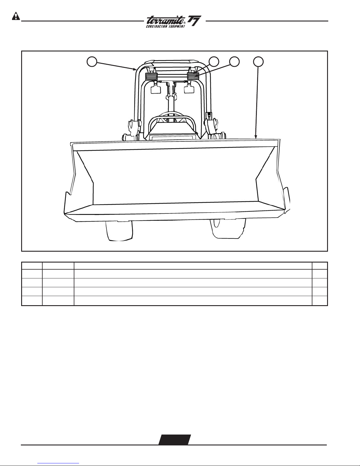
View of Front Loader Bucket
1 2 3
4
ITEM PART NUMBER DESCRIPTION QTY.
1 18043 Assembly, ROPS, Front and Rear, T5C/T5D/T6/T7/T9 (Arm Strut Included) 1
2 77075 Light, Flood, Rectangle, T5B/T5C/T5D/T6/T7/T9 4
3 74047 Bulb, Halogen, T5C/T5D/T6/T7/T9 4
4 13357 Bucket, Loader, 56” Wide, T5D/T7 1
WWW.TERRAMITE.COM
Charleston, WV/USA
2.2
USA 1.800.428.3772
Intl. 1 .304.776.4231
Page 9

View of Right Side of Loader Bucket
Read Operators Manual For SafetyPARTS MANUAL
Copyright © 2007 Terramite Corporation
1
2 3
4
3
4
7
ITEM PART NUMBER DESCRIPTION QTY.
3
6
233
25
1 17176 Pin, 5 1/2”, Arm Link to Arm Cylinder, T5D/T6/T7/T9 4
2 12037 Rod, Link, Loader Arm, T5D/T6/T7/T9 2
3 13200 Pin, 4 3/4”, Front Bucket to Arm, T5C/T5D/T6/T7/T9 4
4 13357 Bucket, Loader, 56” Wide, T5D/T7 1
5 13056 Edge, Cutting, 56” Loader, T5D/T7 1
6
12048 Arm Link Brace, Right, T5D/T6/T7/T9
12079 Arm Link Brace, Left, T5D/T6/T7/T9
2
7 17178 Pin, 5 1/2”, Arm Link to Arm, T5D/T6/T7/T9 2
WWW.TERRAMITE.COM
Charleston, WV/USA
2.3
USA 1.800.428.3772
Intl. 1 .304.776.4231
Page 10
Read Operators Manual For Safety PARTS MANUAL
Copyright © 2007 Terramite Corporation
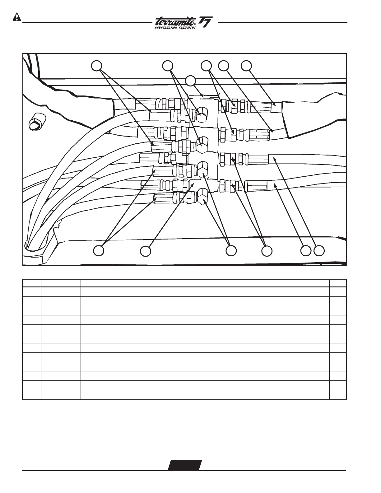
View of Underside of Arm Center
41 2 3 5
12
11
ITEM PART NUMBER DESCRIPTION QTY.
10
9
8
67
1 80132 Hose, 3/8” x 70” 4
2 20063 Fitting, 3/8” MP x 3/8” 90 Swivel, Stubby, T5D/T6/T7/T9 2
o
3 20176 Fitting, 3/8” M x 3/8” FM, Swivel 8
4 80134 Hose, 3/8” x 28” 2
5 80133 Hose, 3/8” x 26” 2
6 88418 Hose, 1/4” x 18” 2
7 80055 Hose, 1/4” x 38” 2
8 20177 Fitting, 3/8” M x 1/4” F, Straight Swivel 4
9 22118 Fitting, 3/8” M 90 x 1/4” F, Swivel 2
o
10 22266 Fitting, 3/8” Tee, Weld-On 4
11 80131 Hose, 1/4” x 70” 2
12 12046 Plate 1
WWW.TERRAMITE.COM
Charleston, WV/USA
2.4
USA 1.800.428.3772
Intl. 1 .304.776.4231
Page 11
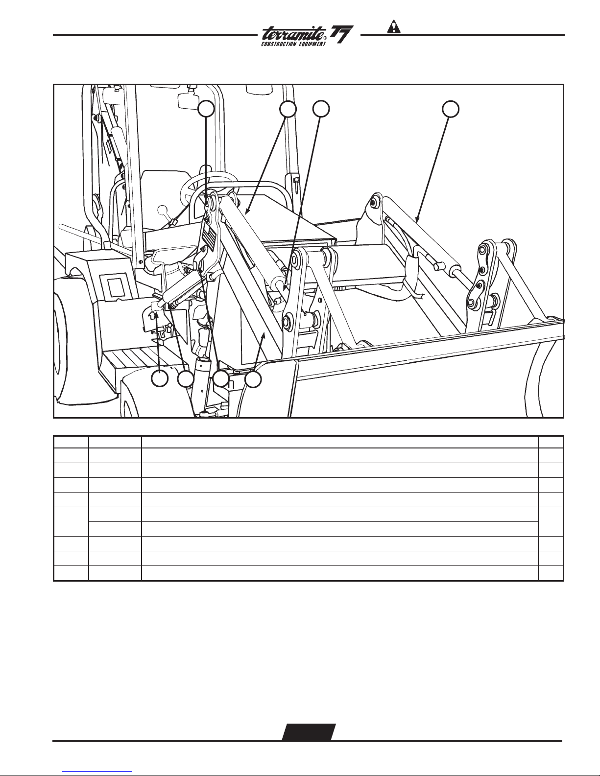
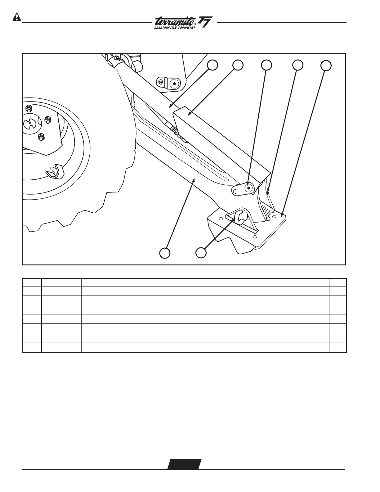
View of Right Side of Arm Assembly
Read Operators Manual For SafetyPARTS MANUAL
Copyright © 2007 Terramite Corporation
1
3
8
7
3
6
5
2
3 4
ITEM PART NUMBER DESCRIPTION QTY.
1 12600 Pin, 5 1/4”, Arm Cylinder to Arm, T5C/T5D/T6/T7/T9 2
2 82074 Cylinder, Front Curl, Right, T5D/T6/T7/T9 1
3 82073 Rod, 22 1/4”, Front Curl, T5D/T6/T7/T9 2
4 82066 Cylinder, Front Curl, Left, T5D/T6/T7/T9 1
5
12074 Assembly, Arm, T5D (Includes Decals)
12075 Assembly, Arm, T7 (Includes Decals)
1
6 17179 Pin, 5 1/2”, Arm Bracket to Arm Cylinder, T5D/T6/T7/T9 2
7 12026 Cylinder, Arm Lift, T5C/T5D/T7 2
8 12301 Pin, 7 7/8”, Arm Cylinder Rod to Frame, T5B/T5C/T5D/T6/T7/T9 1
WWW.TERRAMITE.COM
Charleston, WV/USA
2.5
USA 1.800.428.3772
Intl. 1 .304.776.4231
Page 12

Read Operators Manual For Safety PARTS MANUAL
Copyright © 2007 Terramite Corporation
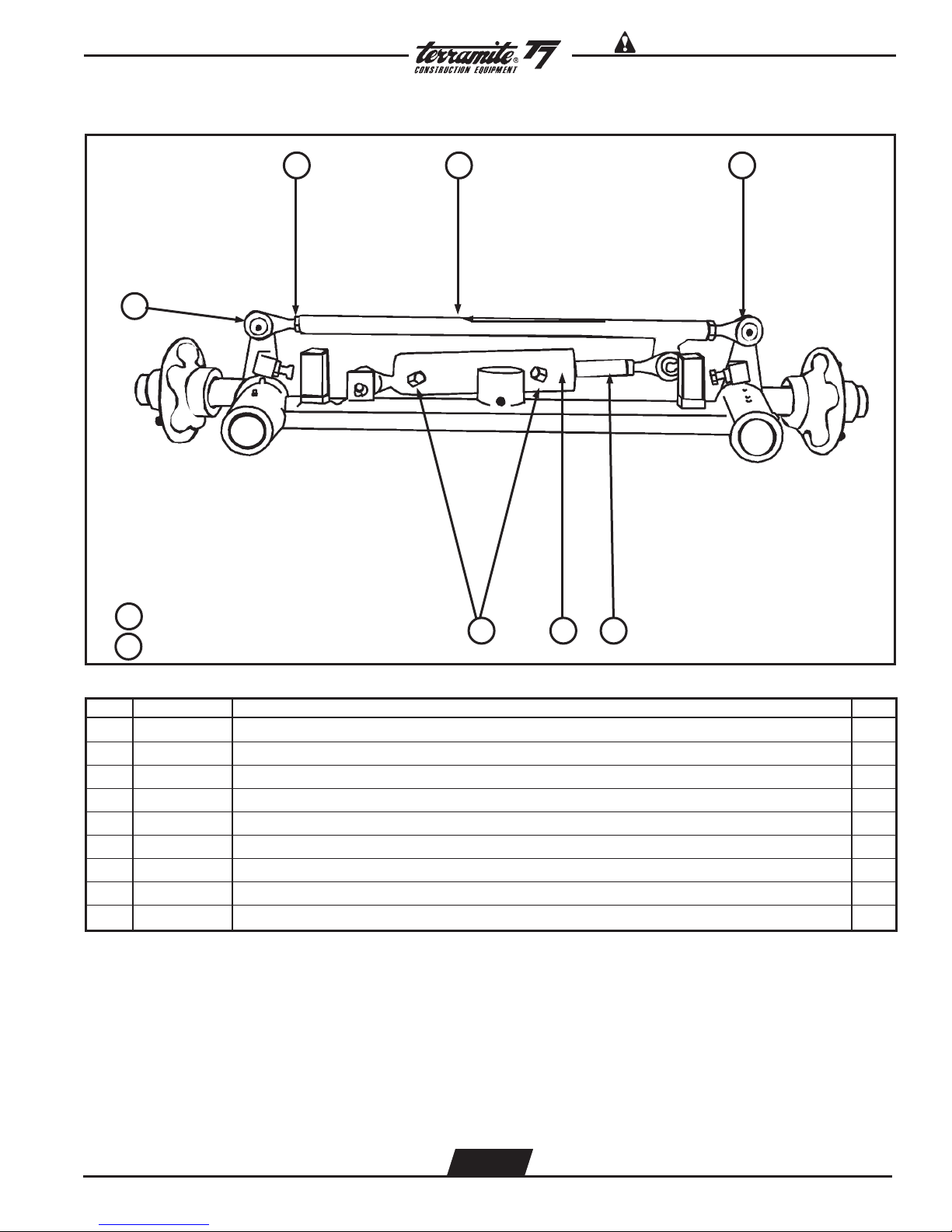
View of Front Axle (Bumper Not Shown) (Prior 1/1/01)
321
9 10 11
8
4 5
76
12
13
ITEM PART NUMBER DESCRIPTION QTY.
1 53091 Bearing, Thrust, F Spin, T5C/T5D/T6/T7/T9 2WD (not shown) 2
2 53212 Axle, Front, T5D/T7 (prior 1/1/01) 1
3 53107 Boss, Spindle Lock, T5D/T6/T9 2WD 2
4 28501 Screw, Set, 1/2” - 20 x 1/2” Plain 4
5 21428 Fitting, Grease 1/4” - 28 Straight 4
6 53050 Spindle, Front, Left, 9 5/8”, T5D/T7/T6/T9 2WD 1
7 53137 Hub, 5 on 4.5”, T5C/T5D/T6/T7/T9 2WD 2
8 53116 Spindle, Front, Right, 9 5/8”, T5D/T7/T6/T9 2WD 1
PIVOT PINS & BOLTS
9 15406 Pin, Front Axle Pivot, 11/4, T5C/T5D/T7 (prior 11/00) 1
10 53081 Nut, Hex, 1 1/4” - 12 Slotted Regular 2
11 15013 Bolt, 1/4” - 20 x 2 1/2” Gr8 Z 2
12 24008 Washer, 1/4” Flat USS 2
13 28504 Nut, 1/4” NC Lock Z 1
WWW.TERRAMITE.COM
Charleston, WV/USA
2.6
USA 1.800.428.3772
Intl. 1 .304.776.4231
Page 13
View of Front Axle (continued)(prior 1/01/01)
9
Read Operators Manual For SafetyPARTS MANUAL
Copyright © 2007 Terramite Corporation
321
7 Complete Assembly
8 Update Kit
ITEM PART NUMBER DESCRIPTION QTY.
6 5 4
1 28503 Nut, Jam, 5/8” NF Z 3
2 53054 Tie Rod, T5C/T5D/T6/T7/T9 1
3 53043 Tie Rod End, w/Kit, T5C/T5D/T6/T7/T9 4
4 25803 Rod, Power Steering, T5C,T5D/T6/T7/T9 2WD 1
5 25815 Cylinder, Power Steering, T5C/T5D/T6/T7/T9 1
6 23174 Fitting, 1/4” M x 1/4”F 45° Degrees 2
7 53092 Assembly, Axle, Front, T5D/T7 (Completely Assembled) 1
8 53131 Update Kit for Axle (prior to 1/01/01) 1
9 53221 Tie Rod, Ball Socket After Ser# 2370201 1
WWW.TERRAMITE.COM
Charleston, WV/USA
2.7
USA 1.800.428.3772
Intl. 1 .304.776.4231
Page 14
Read Operators Manual For Safety PARTS MANUAL
Copyright © 2007 Terramite Corporation
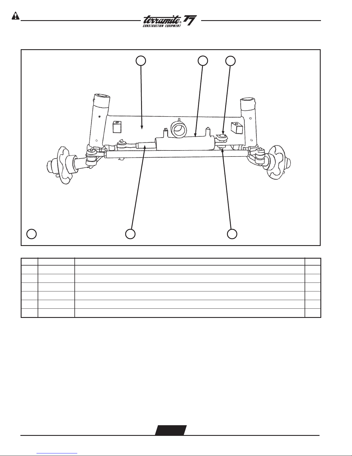
View of Front Axle - Ball Socket Style (Bumper Not Shown)(After 1/1/01)
1 2
3
6 Complete Assembly
ITEM PART NUMBER DESCRIPTION QTY.
45
1 53201 Axle, Front, T7/T9 2W 1
2 81212 Cylinder, Power Steering, Ball Socket Style, T5C/T7/T9 2WD 1
3 24028 Pin, Clevis, 5/8 x 2 1/4”1
4 53160 Pin, Cotter, 1/8 x 1 3/4”1
5 25803 Rod, Power Steering, T5C/T5D/T6/T7/T9 2WD 1
6 15162 Assembly, Axle, Front, Ball Socket,
T7/T9 2WD 1
WWW.TERRAMITE.COM
Charleston, WV/USA
2.8
USA 1.800.428.3772
Intl. 1 .304.776.4231
Page 15

View of Hub Assembly and Spindle
Read Operators Manual For SafetyPARTS MANUAL
Copyright © 2007 Terramite Corporation
121110987654321
13 Hub Assembly
ITEM PART NUMBER DESCRIPTION QTY.
1
53116 Spindle, Front, Right, T5D/T7 T6/T9 2WD
53050 Spindle, Front, Left, T5D/T7 T6/T9 2WD
1
2 53111 Seal, Front, Hub, T5C/T5D/T6/T7/T9 1
3 53123 Bearing, Front, Inner, T5C/T5D/T6/T7/T9 1
4 53124 Race, 5 on 5.5, Front, Inner, T5C/T5D/T6/T7/T9 1
5 53137 Hub, 5 on 4.5, T5C/T5D/T6/T7/T9 1
6 53058 Race, Old Style, In & Out and New Style Outer, T5C/T5D/T6/T7/T9 1
7 53125 Bearing, Front, Outer, T5C 1
8 53140 Washer, 3/4”, SAE Z, Front Axle 1
9 53150 Nut, Castelated, 3/4”, Front Hub 1
10 53160 Pin, Cotter, 1/8 x 13/4”1
11 53170 Cap, Dust, T3/T4/T5C/T5D/T6/T7/T9 1
12 28506 Nut, Lug, 1/2” - 20 ID x 13/16” OD, Front & Rear 5
13 53136 Assembly, Hub, 5 on 4.5 (Spindle Not Included) 1
14 53227 Bearing Kit w/no Hub 1
WWW.TERRAMITE.COM
Charleston, WV/USA
2.9
USA 1.800.428.3772
Intl. 1 .304.776.4231
Page 16

Read Operators Manual For Safety PARTS MANUAL
Copyright © 2007 Terramite Corporation
View of Right Front Tire and Rim
1 32
6 Tire Assembly
ITEM PART NUMBER DESCRIPTION QTY.
45
1 53170 Cap, Dust, T3/T5C/T5D/T6/T7/T9 1
2 28506 Nut, Lug, 1/2” - 20 ID x 13/16” OD, Front & Rear 5
3 51275 Tire, Front, 23” x 10.5” x 12”, T6/T7/T9 1
4 51273 Valve, Tire, Front 1
5 50017 Rim, Front, T5D/T6/T7/T9 1
6 51019 Assembly, Tire & Rim, Front, T6/T7/T9 1
WWW.TERRAMITE.COM
Charleston, WV/USA
2.10
USA 1.800.428.3772
Intl. 1 .304.776.4231
Page 17

View of Right Side of Tractor
Read Operators Manual For SafetyPARTS MANUAL
Copyright © 2007 Terramite Corporation
1
2345678
ITEM PART NUMBER DESCRIPTION QTY.
1 15126 Hood, T5D/T7 1
2 80055 Hose, 1/4” x 38” 1
3 20174 Fitting, 1/4” MP x 1/4” FM Swivel 1
4 12301 Pin, 7 7/8”, Arm Cylinder, Rod to Frame, T5B/T5C/T5D/T6/T7/T9 1
5 80025 Wrap, Hose, 4” (Sold per Foot) 4
6 80132 Hose, 3/8 x 70” 2
7 80131 Hose, 1/4” x 70” 2
8 12300 Pin, 6 7/8”, Arm to Frame, T5B/T5C/T5D/T6/T7/T9 1
WWW.TERRAMITE.COM
Charleston, WV/USA
2.11
USA 1.800.428.3772
Intl. 1 .304.776.4231
Page 18

Read Operators Manual For Safety PARTS MANUAL
Copyright © 2007 Terramite Corporation
View of Left Side of Tractor
1 2
35 46
ITEM PART NUMBER DESCRIPTION QTY.
1 12056 Strut, Lift, Arm, Loader, T5C/T5D/T6/T7/T9 1
2 17200 Pin, Quick Release w/Ring Grip, T5C/T5D/T6/T7/T9 1
3 22109 Bolt, 1/2 x 3 1/2” NC Gr8 Z 1
4 15542 Latch, Hood, T5D/T6/T7/T9 1
5 17198 Pin, 8 1/2”, Arm Lift Cylinder to Strut, T5C/T5D/T6/T7/T9 1
6 21003 Oil Filter 25HP Kubota 1
WWW.TERRAMITE.COM
Charleston, WV/USA
2.12
USA 1.800.428.3772
Intl. 1 .304.776.4231
Page 19

Read Operators Manual For SafetyPARTS MANUAL
Copyright © 2007 Terramite Corporation
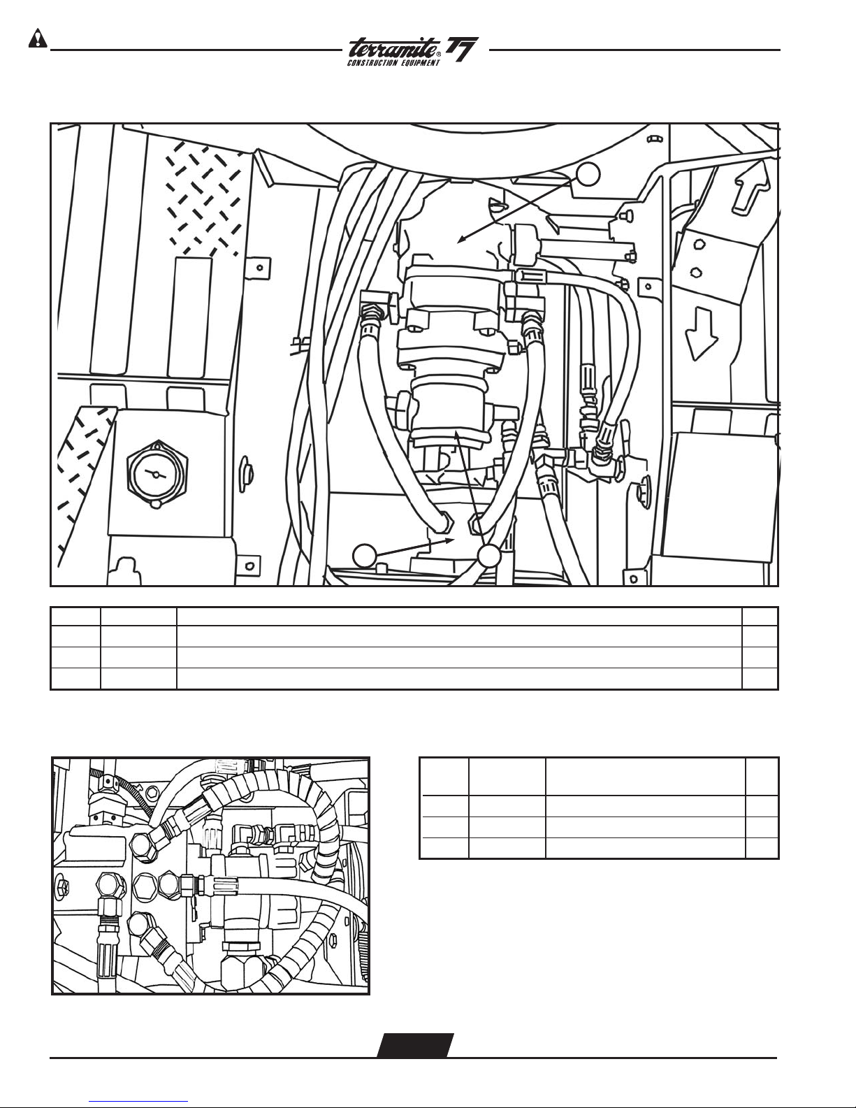
Right Side of Diesel Engine Compartment - Kubota (Without Air Filter)
3
ITEM PART NUMBER DESCRIPTION QTY.
5/
1 15506 Filter, Fuel,
16
”, T5C/T5D/T6/T7/T9 (not shown) 1
2 21003 Filter, Oil, 25hp., T5D/T6/T7/T9 1
3 43396 Filter, Fuel Element, 25 &32.5hp., T5D/T6/T7/T9 1
WWW.TERRAMITE.COM
Charleston, WV/USA
2.13
USA 1.800.428.3772
Intl. 1 .304.776.4231
Page 20

Read Operators Manual For Safety PARTS MANUAL
Copyright © 2007 Terramite Corporation
View of Diesel Air Filter Assembly
1
ITEM PART NUMBER DESCRIPTION QTY.
1 41056 Kit, Air Cleaner Filter, 3 Cylinder, Kubota 1
2 41074 Filter, Air (Not Shown) 1
WWW.TERRAMITE.COM
Charleston, WV/USA
2.14
USA 1.800.428.3772
Intl. 1 .304.776.4231
Page 21

View of Muffler Assembly - Diesel
Read Operators Manual For SafetyPARTS MANUAL
Copyright © 2007 Terramite Corporation
2
ITEM PART NUMBER DESCRIPTION QTY.
1 40037 Assembly, Engine, Kubota, 25hp. 1
2 42071 Muffler, Kubota, 25hp. 1
WWW.TERRAMITE.COM
Charleston, WV/USA
2.15
USA 1.800.428.3772
Intl. 1 .304.776.4231
Page 22

Read Operators Manual For Safety PARTS MANUAL
Copyright © 2007 Terramite Corporation
Left Side of Diesel Engine Compartment - Kubota (Without Air Filter)
2
ITEM PART NUMBER DESCRIPTION QTY.
1 15505
5
/16" in line (Not Shown) 1
2 21003 Filter, Oil, Engine, Kubota 1
WWW.TERRAMITE.COM
Charleston, WV/USA
2.16
USA 1.800.428.3772
Intl. 1 .304.776.4231
Page 23

View Right Side of Kohler Engine
Read Operators Manual For SafetyPARTS MANUAL
Copyright © 2007 Terramite Corporation
1 2 3 4
ITEM PART NUMBER DESCRIPTION QTY.
1 40027 Assembly, Engine, Command 20hp. (V-Twin) 1
2 70075 Plug, Spark RC/12yc/71 1
3 43233 Starter, CH20 1
4 42023 Muffler, Center Outlet, Kohler Command 20hp. 1
WWW.TERRAMITE.COM
Charleston, WV/USA
2.17
USA 1.800.428.3772
Intl. 1 .304.776.4231
Page 24

Read Operators Manual For Safety PARTS MANUAL
Copyright © 2007 Terramite Corporation
Kohler Engine Leftside View
123
ITEM PART NUMBER DESCRIPTION QTY.
1 40097 Pump, Fuel, Kohler Command 20 hp 1
2 15503 Filter, Gas Fuel,
1/
"1
4
3 21014 Filter, Oil, Engine, CH 20 1
WWW.TERRAMITE.COM
Charleston, WV/USA
2.18
USA 1.800.428.3772
Intl. 1 .304.776.4231
Page 25

View of Power Steering Gear
1
Read Operators Manual For SafetyPARTS MANUAL
Copyright © 2007 Terramite Corporation
3
2
4
5
ITEM PART NUMBER DESCRIPTION QTY.
1 15106 Gear, Power Steering, T5D/T6/T7/T9 1
2 20033 Fitting, #8 O-Ring x #6 JIC, T5D/T7/T9/Sweeper 2
3 20032 Fitting, #8 O-Ring x #4 JIC FM 2
4 80176 Hose, 1/4” X 65”, 1/4 MP x #4 Short JIC 90 2
5 88658 Hose, 3/8” x 58”, #6 Short JIC 90 x 3/8 MP 2
WWW.TERRAMITE.COM
Charleston, WV/USA
2.19
USA 1.800.428.3772
Intl. 1 .304.776.4231
Page 26
Read Operators Manual For Safety PARTS MANUAL
Copyright © 2007 Terramite Corporation
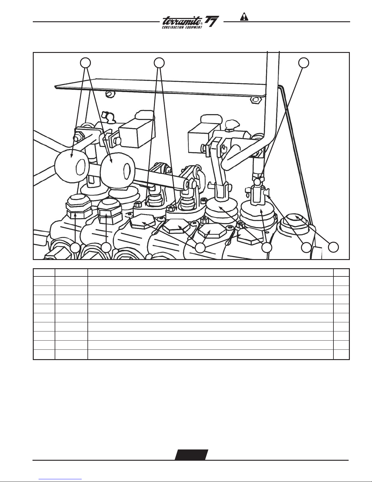
View of Front Valve w/Fittings
1
2
3
4
9 8
ITEM PART NUMBER DESCRIPTION QTY.
7 6
5
1 22784 Fitting, 1/2"M 90 x 1/4"F, Swivel 2
2 20786 Fitting, 1/2"MP x 3/8"F 90, Swivel 2
3 22278 Fitting, 1/2"F 90 x 1/2"F, Swivel 1
4 20010 Fitting, Nipple, 1/2" x 3" 1
5 85015 Valve, Front 1
6 13083 Detent. Spring (Not Shown) 1
7 13943 Relief Valve, Loader (Not Shown) 1
8 20094 Fitting, Reducer, 3/4" x 1/2" FM 1
9 21978 Fitting, 1/2"M 90 x 1/2"F, Swivel 1
WWW.TERRAMITE.COM
Charleston, WV/USA
2.20
USA 1.800.428.3772
Intl. 1 .304.776.4231
Page 27

Read Operators Manual For SafetyPARTS MANUAL
View of Loader Valve Assembly and Battery - Perkins
Copyright © 2007 Terramite Corporation
1 2 3 4 5 6
ITEM PART NUMBER DESCRIPTION QTY.
7
1 80132 Hose, 3/8" x 70" 2
2 80131 Hose, 1/4" x 70" 2
3 88878 Hose, 1/2" x 78" (not shown) 1
4 88845 Hose, 1/2" x 45" 1
5 72028 Cable, Battery to Ground, Black, T5C/T5D/T6/T7/T9 1
6 72038 Cable, Battery to Starter, T5C/T5D/T6/T7/T9 1
7 77022 Battery, Group 26, All Tractors/SCR/Sweeper 1
WWW.TERRAMITE.COM
Charleston, WV/USA
2.21
USA 1.800.428.3772
Intl. 1 .304.776.4231
Page 28

Read Operators Manual For Safety PARTS MANUAL
Copyright © 2007 Terramite Corporation
View of Front Valve Linkage Assembly
2 3 4 5 6 7
1
ITEM PART NUMBER DESCRIPTION QTY.
1 13947 Link, “L”, Front Valve, All Tractors 1
2 13965 Linkage, Ball-Socket, Wobblestick, All Tractors 1
3 13413 Pin, Cotter, 3/32” x 5/8”, Linkage, Valve, All Tractors 1
4 25500 Nut, 5/16” - 24 NF Jam 1
5 13944 Block, Pivot, Wobblestick, Front, T5C/T5D/T6/T7/T9 1
6 13411 Link, “U”, Valve, All Tractors 1
7 13995 Bolt, Wobblestick Hinge, Front, All Tractors 1
WWW.TERRAMITE.COM
Charleston, WV/USA
2.22
USA 1.800.428.3772
Intl. 1 .304.776.4231
Page 29
Read Operators Manual For SafetyPARTS MANUAL
Copyright © 2007 Terramite Corporation
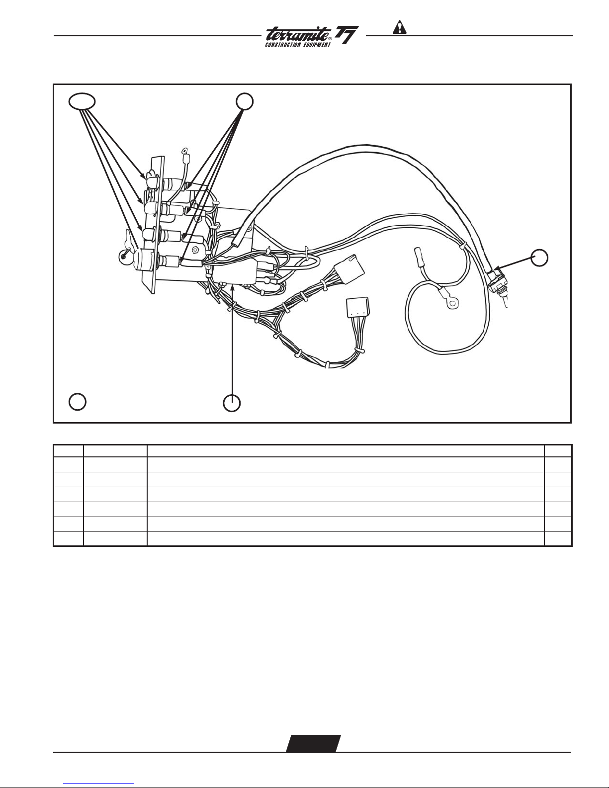
View of Left Side of Diesel Dash Wiring Harness - Perkins
1&2
3
5
6 Entire Assembly
ITEM PART NUMBER DESCRIPTION QTY.
4
1 74038 Lens, Warning Light, Red, Diesel, T5C/T5D/T6/T7/T9 4
2 74039 Bulb, Light, Warning 4
3 74037 Base, Warning Light 4
4 70038 Relay, Timer & Glow Plug, T7/T9 1
5 74000 Switch, Toggle, Double Throw, T5D/T6/T7/T9 1
6 72059 Harness, Wiring, Dash, Perkins, T5C/T5D/T7 1
WWW.TERRAMITE.COM
Charleston, WV/USA
2.23
USA 1.800.428.3772
Intl. 1 .304.776.4231
Page 30

Read Operators Manual For Safety PARTS MANUAL
Copyright © 2007 Terramite Corporation
View of Right Side of Diesel Dash Wiring Harness - Perkins
1
2
3 45
6
ITEM PART NUMBER DESCRIPTION QTY.
1 70010 Breaker, Circuit, 50 Amp. 1
2 74036 Breaker, Circuit, 15 Amp., T7/T9 2
3 77080 Hourmeter, All Tractors 1
4 14120 Plate, Instrument Panel, Diesel, Perkins, T6/T7/T9 1
5 70335 Switch, Ignition, 3 Prong 1
6 72049 Diode Harness, Dual, T6/T7/T9 1
WWW.TERRAMITE.COM
Charleston, WV/USA
2.24
USA 1.800.428.3772
Intl. 1 .304.776.4231
Page 31

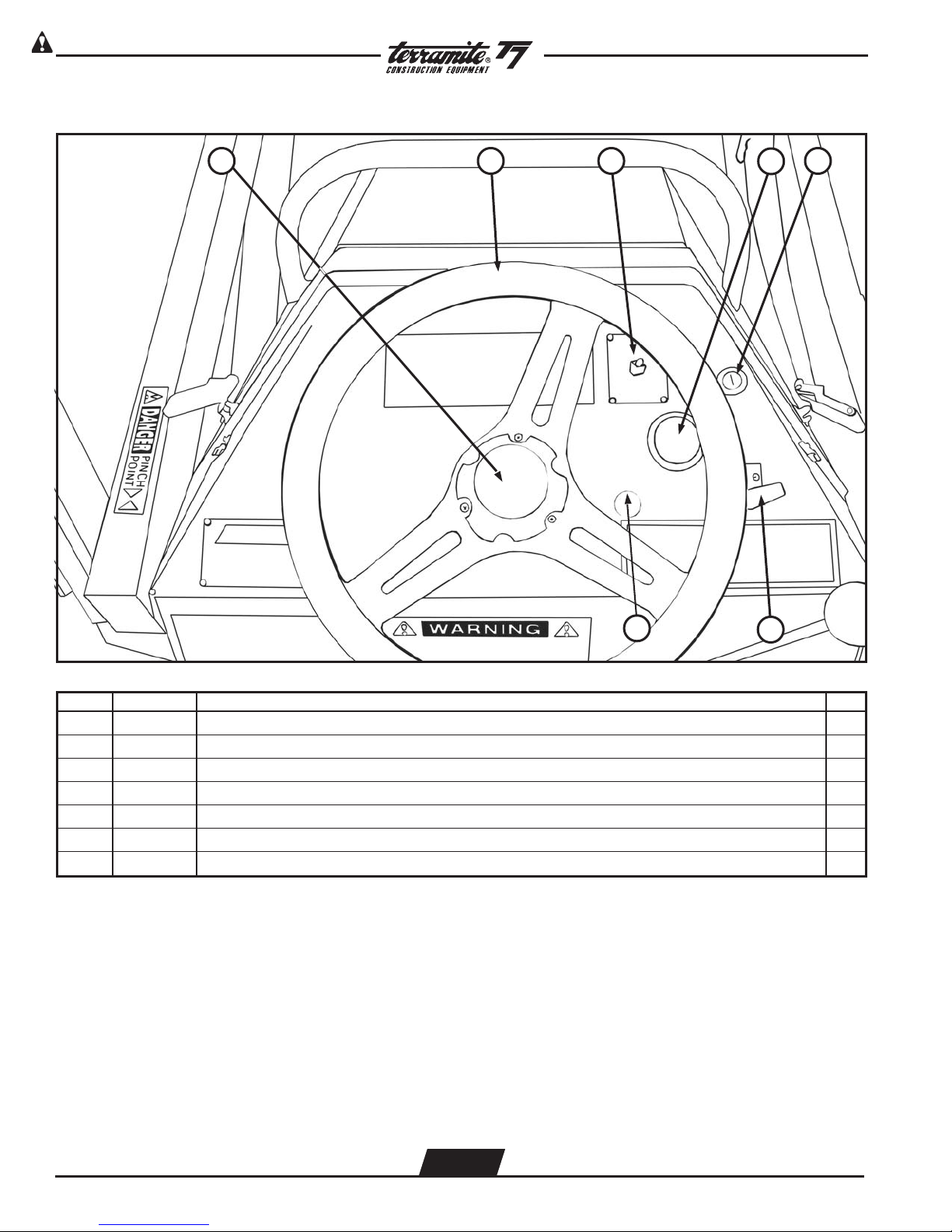
View of Operator Position Facing Dash (Diesel)
Read Operators Manual For SafetyPARTS MANUAL
Copyright © 2007 Terramite Corporation
1 2 3 4
11
12
5678
ITEM PART NUMBER DESCRIPTION QTY.
1 13140 Cable, Throttle, Diesel, T7/T9 1
2 74000 Switch, Toggle, Double Throw, T5D/T6/T7/T9 1
3 77080 Hourmeter, All Tractors 1
4
70335 Switch, Ignition, T6/T9
70111 Switch, Ignition, Perkins T6/T9 (after SN 229x0120)
1
5 13942 Knob, Red, Wobblestick Handle, Valve, All Tractors 1
6 13072 Handle, Wobblestick, Front, All Tractors 1
9 13136 Cap, Center, Steering Wheel 1
10 13003 Wheel, Steering, T5C/T5D/T6/T7/T9 1
11 70111 Perkins, Key Switch (after SN#227x0107) 1
12 70040 Kubota, Key Switch 1
WWW.TERRAMITE.COM
Charleston, WV/USA
2.25
USA 1.800.428.3772
Intl. 1 .304.776.4231
Page 32
Read Operators Manual For Safety PARTS MANUAL
Copyright © 2007 Terramite Corporation
View of Operator PositionFacing Dash (Gas)
1 2 5
3
4
7
ITEM PART NUMBER DESCRIPTION QTY.
6
1 13136 Cap, Center, Steering Wheel 1
2 13003 Wheel, Steering, T5C/T5D/T6/T7/T9 1
3 74000 SwitchToggle, Double Throw, T5D/T6/T7/T9 1
4 77080 Hourmeter, All Tractors 1
5 Serial Number Must Be Provided for Correct Keyswitch and Keys 3
6 13142 Cable, Throttle Command/Honda T5C/T5D/T7 1
7 14801 Cable, Choke 1
WWW.TERRAMITE.COM
Charleston, WV/USA
2.26
USA 1.800.428.3772
Intl. 1 .304.776.4231
Page 33

View of Transmission Assembly - Diesel
1
2
17
10
Read Operators Manual For SafetyPARTS MANUAL
Copyright © 2007 Terramite Corporation
3
4
12
11
8
9
ITEM PART NUMBER DESCRIPTION QTY.
5
6
7
1 11128 Spring Assembly 1
2 88820 Hose,1/2" x 20" 2
3 88827 Hose,3/4" x 27" 1
4 80201 Hose,1/2" x 57" 1
5 66007 Gear Pump 1
6 81624 Hose,1" x 24" 1
7 80250 Hose,3/8" x 25" 1
8 21032 Filter, In Line Hydraulic 1
9 80233 Hose,1/2" x 80" 1
10 80251 Hose,3/8" x 25" 1
11 88659 Hose,3/8" x 58" 1
12 88831 Hose,1/2" x 31" 1
13 80232 Hose,1/2" x 47" Oil Filter to Back Valve (Not Shown) 1
14 80229 Hose,1/2" x 123" Oil Cooler to Oil Filter (Not Shown) 1
15 80099 Hose,1/2" x 96" Front Valve to Oil Cooler (Not Shown) 1
16 80230 Hose, 1/4" x 65" Power Steering (Not Shown) 2
17 64200 Sauer - Danfoss Transmission 1
WWW.TERRAMITE.COM
Charleston, WV/USA
2.27
USA 1.800.428.3772
Intl. 1 .304.776.4231
Page 34
Read Operators Manual For Safety PARTS MANUAL
Copyright © 2007 Terramite Corporation
View of Transmission Assembly - Gas
1
3 2
ITEM PART NUMBER DESCRIPTION QTY.
1 64055 Transmission, Eaton, T5C/T5D/T7 1
2 66000 Pump, Double Gear, T5C/T5D/T7 1
3 64003 Motor, Torque, Parker/TRW, All Tractors 1
Sunstrand Transmission Assembly
ITEM PART NUMBER DESCRIPTION QTY.
1 64200 Transmission 1
2 88820 Hose 1/2 x 20" 2
3 66000 Pump, Double Gear 1
WWW.TERRAMITE.COM
Charleston, WV/USA
2.28
USA 1.800.428.3772
Intl. 1 .304.776.4231
Page 35
View from Right of Foot Pedal Control
1 2
Read Operators Manual For SafetyPARTS MANUAL
Copyright © 2007 Terramite Corporation
8
ITEM PART NUMBER DESCRIPTION QTY.
67
45
3
1 11600 Pedal, Foot 1
2 11628 Bolt, Pedal Stop, T5C/T5D/T7 2
3 11627 Block, Pillow, Bearing, T5C/T5D/T6/T7/T9 1
4 11629 Bolt, Spring Centering, T5C/T5D/T7 1
5 13029 Spring, Pedal, Hairpin, T5C/T5D/T6/T7/T9 1
6 11610 Block, Pedal, T5C/T5D/T6/T7/T9 1
7 11620 Shaft, Pedal, T5C/T5D/T6/T7/T9 1
8 16177 Tape, Pedal, Anti-Skid 1
WWW.TERRAMITE.COM
Charleston, WV/USA
2.29
USA 1.800.428.3772
Intl. 1 .304.776.4231
Page 36

Read Operators Manual For Safety PARTS MANUAL
Copyright © 2007 Terramite Corporation
View from Right Side of Hydraulic Tank
1
ITEM PART NUMBER DESCRIPTION QTY.
1 22204 Cap, Hydraulic, w Dipstick & Breather, T5C/T5D/T6/T7/T9 2WD 1
WWW.TERRAMITE.COM
Charleston, WV/USA
2.30
USA 1.800.428.3772
Intl. 1 .304.776.4231
Page 37

View from Left Side of Fuel Tank
Read Operators Manual For SafetyPARTS MANUAL
Copyright © 2007 Terramite Corporation
1
ITEM PART NUMBER DESCRIPTION QTY.
2&3
1 11299 Gauge, Fuel, T5D/T6/T7/T9 1
2 15005 Cap, Safety, Green, (Diesel) T5C/T5D/T6/T7/T9 1
3 11282 Cap, Safety, Red, (Gas), T5B/T5C/T5D/T7/Screed 1
WWW.TERRAMITE.COM
Charleston, WV/USA
2.31
USA 1.800.428.3772
Intl. 1 .304.776.4231
Page 38

Read Operators Manual For Safety PARTS MANUAL
Copyright © 2007 Terramite Corporation
View of Hydraulic Filter Assembly
1
2
ITEM PART NUMBER DESCRIPTION QTY.
1 21030 Filter, Hydraulic, Spin On 1
2 21025 Assembly, Filter, Hydraulic 1
View of Hydraulic Filter
3
1
2
ITEM PART NUMBER DESCRIPTION QTY.
1 21029 Filter Head 1
2 21030 Filter Hydraulic 1
3 10357 Bracket Hydraulic Filter 1
WWW.TERRAMITE.COM
Charleston, WV/USA
2.32
USA 1.800.428.3772
Intl. 1 .304.776.4231
Page 39
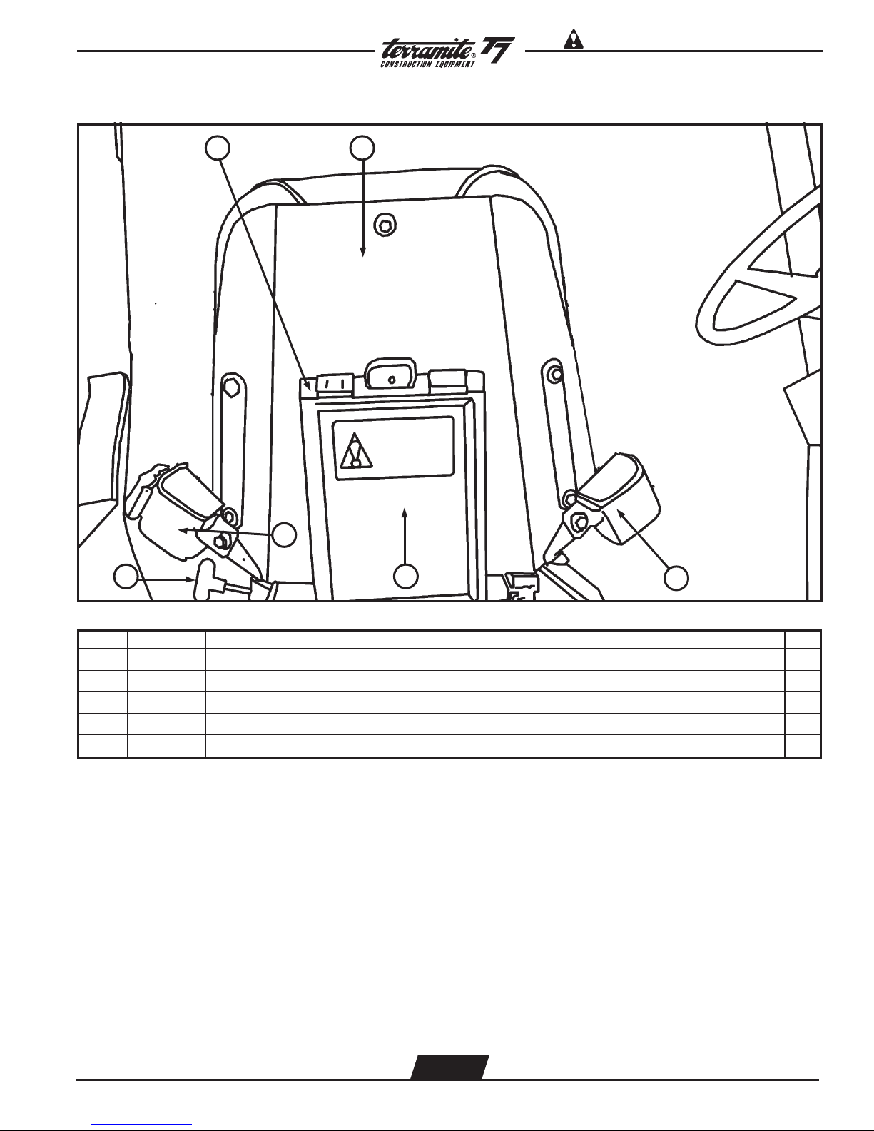
View from Back of Seat
1 2
Read Operators Manual For SafetyPARTS MANUAL
Copyright © 2007 Terramite Corporation
3
6
ITEM PART NUMBER DESCRIPTION QTY.
4
3
1 11911 Box, Manual, Operator’s Seat 1
2 14260 Assembly, Seat, w/Swivel Disc w/Arm, T5D/T6/T7/T9 1
3 11903 Belt, Seat, T5C/T5D/T6/T7/T9/Sweeper 1
4 95086 Manual, Operator's, All Tractors (Not Shown) 1
5 14011 Knob, Seat Shaft 1
WWW.TERRAMITE.COM
Charleston, WV/USA
2.33
USA 1.800.428.3772
Intl. 1 .304.776.4231
Page 40
Read Operators Manual For Safety PARTS MANUAL
Copyright © 2007 Terramite Corporation
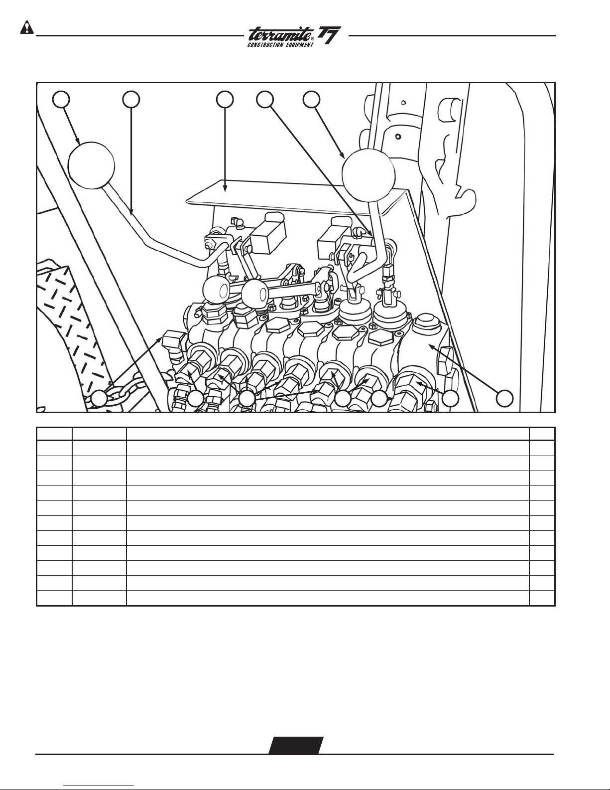
View from Operator Position of Rear Valve (Straight Boom - Non 180 Only)
1 2 3 4 1
567891011
ITEM PART NUMBER DESCRIPTION QTY.
1 13942 Knob, Red, Wobblestick Handle, Valve, T5C/T5D/T6/T7/T9 2
2 13073 Handle, Wobblestick, Left Rear 2
3 14050 Decal, Wobblestick and Operator Hazard 1
4 13123 Handle, Wobblestick, Right Rear 1
5 13400 Valve, Rear 1
6 25128 Fitting, #12 O’ring x 1/2” FPT 2
7 21788 Fitting, 1/2”M x 1/2”FM 45, Swivel 2
8 25286 Fitting, 3/4”MB x 3/8”F, Bushing HD 12
9 21764 Fitting, 3/8”M x 1/4”F 45, Swivel 9
10 21765 Fitting, 3/8”MP x 1/4”FP 45, Restrictor 3
11 25718 Fitting, 7/8”MP 90 x 1/2”, Swivel 1
WWW.TERRAMITE.COM
Charleston, WV/USA
2.34
USA 1.800.428.3772
Intl. 1 .304.776.4231
Page 41
Read Operators Manual For SafetyPARTS MANUAL
Copyright © 2007 Terramite Corporation
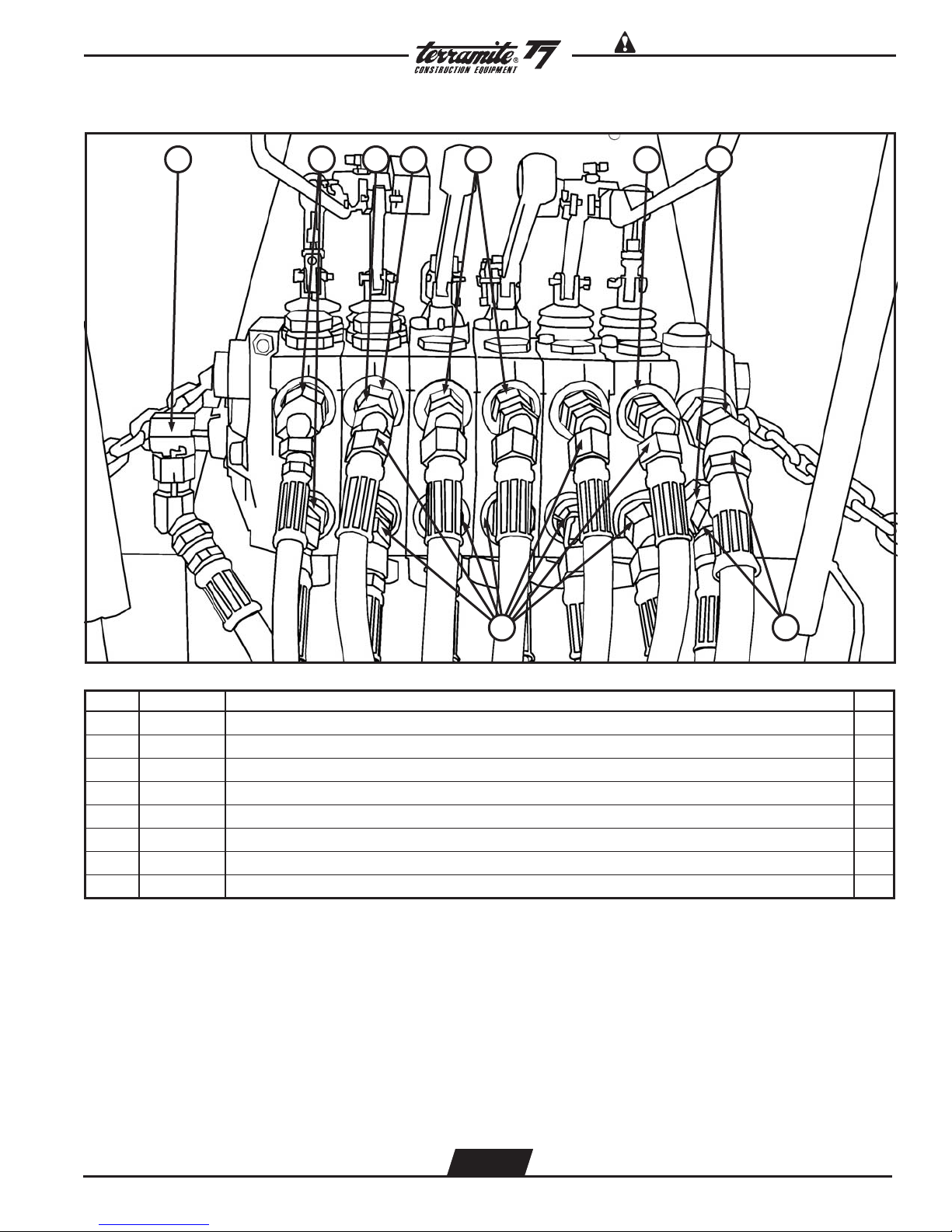
View from Operator Position of Rear Valve (Straight Boom - Non 180 Only)
21
3
9
ITEM PART NUMBER DESCRIPTION QTY.
8
7
56
4
1 13431 Handle, Outrigger, T5C/T5D/T6/T7/T9 2
2 13410 Bracket, Aluminum, Rear Valve Handle 2
3 16410 Wobblestick Eye Bolt 2
4 13429 Valve, Main Relief 1
5 13418 Pin, Pivot, Valve Hose Link, T5C/T5D/T7 8
6 13423 Valve, Boot Spool Protector 4
7 13401 Kit, Load Check 9
8 13456 Relief, Port 2600# 1
9 13454 Relief, Port 2000# 2
WWW.TERRAMITE.COM
Charleston, WV/USA
2.35
USA 1.800.428.3772
Intl. 1 .304.776.4231
Page 42

Read Operators Manual For Safety PARTS MANUAL
Copyright © 2007 Terramite Corporation
View of Operator Position at Rear Valve (Prior to 1-1-01 Non 180 Only)
1 2 3
4
6
ITEM PART NUMBER DESCRIPTION QTY.
5
1 13073 Handle, Wobblestick, Left Rear, T5C/T5D/T6/T7/T9 1
2 13431 Handle, Outrigger, T5C/T5D/T6/T7/T9 2
3 13123 Handle, Wobblestick, Right Rear, T5C/T5D/T6/T7/T9 1
4 13942 Knob, Red Wobblestick Handle, Valve, T5C/T5D/T6/T7/T9 2
5 15102 Cover, Rear Valve (Boom Latch), T5C/T7/T9 1
6 13135 Cable, Boom Latch Control, T-Handle, T7/T9 1
7 22222 Spring For Boom Latch 1
8 22023 Washers For Latch 1
WWW.TERRAMITE.COM
Charleston, WV/USA
2.36
USA 1.800.428.3772
Intl. 1 .304.776.4231
Page 43
Read Operators Manual For SafetyPARTS MANUAL
Copyright © 2007 Terramite Corporation
View from Operator Position of Rear Valve Curved Boom Prior to 1-1-01 Non 180 Only
1 2 3
4
2 5
6
8
ITEM PART NUMBER DESCRIPTION QTY.
1 25718 Fitting, 7/8" MP 90 x 1/2", Swivel 2
2 21765 Fitting, 3/8" MP x 1/4" FP 45 - Restrictor 2
o
o
7
3 13048 Restrictor, w/spring, Rear Valve 1
4 85031 Checks, Anti-Cavitation, (Not Shown) 2
5 25286 Fitting, 3/4" MB x 3/8" F, Bushing HD 12
6 20065 Fitting, #12 O'Ring x 1/2" FPT 2
7 21788 Fitting, 1/2" M x 1/2" FM 45, Swivel 2
8 21764 Fitting, 3/8" M x 1/4" F 45, Swivel 8
WWW.TERRAMITE.COM
Charleston, WV/USA
2.37
USA 1.800.428.3772
Intl. 1 .304.776.4231
Page 44

Read Operators Manual For Safety PARTS MANUAL
Copyright © 2007 Terramite Corporation
Curved Boom Prior to 1-1-01
View from Operator Position of Backhoe Valve
Non 180 Only
1 2 3 4
5
6
10
ITEM PART NUMBER DESCRIPTION QTY.
2
8
8
549
7
1 88425 Hose, 1/4” x 25” 1
2 80061 Hose, 1/4” x 72” 2
3 80058 Hose, 1/4” x 51” 2
4 80020 Hose, 1/4” x 98” 2
5 80021 Hose, 1/4” x 136” 2
6 88840 Hose, 1/2” x 40” 1
7 88857 Hose, 1/2” x 57” 1
8 80054 Hose, 1/4” x 36” 2
9 80155 Hose, 1/4” x 24” 1
10 88880 Hose, 1/2” x 80” 2
WWW.TERRAMITE.COM
Charleston, WV/USA
2.38
USA 1.800.428.3772
Intl. 1 .304.776.4231
Page 45

Read Operators Manual For SafetyPARTS MANUAL
Copyright © 2007 Terramite Corporation
View from Operator Position of Rear Valve
1 2 3 4 2 5
Prior to 1-1-01
Non 180 Only
7869 9 6
ITEM PART NUMBER DESCRIPTION QTY.
1 25500 Nut, 5/16” - 24 NF Jam 5
2 13444 Block, Pivot, Universal Rear, T5C/T5D/T6/T7/T9 1
3 21429 Fitting, Grease, 1/4” 90°D 7
4 14052 Plate, Wobblestick & Operator Hazard, T5C/T5D/T6/T7/T9 1
5 13965 Linkage, Ball-Socket, Wobblestick, All Tractors 3
6 13418 Pin, Pivot, Valve Hose Link, T5C/T5D/T6/T7 10
7 13443 Link Bar, Wobblestick Connecting, T5C/T5D/T6/T7/T9 3
8 13411 Link, “U”, Valve All Tractors 3
9 13410 Bracket, Aluminum, Rear Valve Handle, T6/T9 2
WWW.TERRAMITE.COM
Charleston, WV/USA
2.39
USA 1.800.428.3772
Intl. 1 .304.776.4231
Page 46

Read Operators Manual For Safety PARTS MANUAL
Copyright © 2007 Terramite Corporation
View of Operator Position at Rear Valve (180 Swing)
21 3
4
5
ITEM PART NUMBER DESCRIPTION QTY.
1 13135 Cable, Boom Latch Control, T-Handle, T7/T9 1
2 84046 Wobblestick, Right Rear, V10-1294 Kit Pivot Section 1
3 13942 Knob, Red Wobblestick Handle, Valve, T5C/T5D/T6/T7/T9 2
4 84045 Handle, Wobblestick Left and Right, V10-1294 2
5 85120 Handle Outrigger/Offset V10-1294 1
WWW.TERRAMITE.COM
Charleston, WV/USA
2.40
USA 1.800.428.3772
Intl. 1 .304.776.4231
Page 47

Read Operators Manual For SafetyPARTS MANUAL
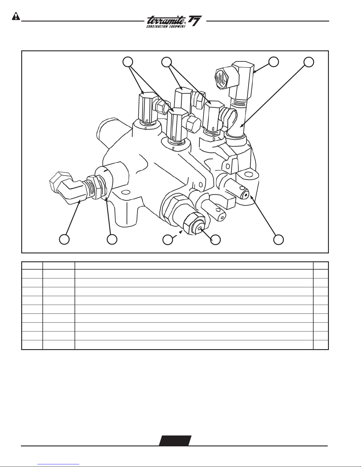
View of Fitting Location for Rear Valve (180 Swing)
21 3
Copyright © 2007 Terramite Corporation
5
4
6
ITEM PART NUMBER DESCRIPTION QTY.
1 20039 Fitting, #10 O-Ring x #8 JIC 90 1
2 20156 Fitting, #8 O-Ring x #6 JIC 90 6
3 20007 Fitting, #10 O-Ring - 7/8MB x 1/2" F, Bushing 1
4 20192 Fitting, 1/2MB x #8 JIC Long 90 1
5 20039 Fitting, #10 O-Ring x #8 JIC 90 1
6 20149 Fitting, #8 MP x #8M JIC Long 90 6
WWW.TERRAMITE.COM
Charleston, WV/USA
2.41
USA 1.800.428.3772
Intl. 1 .304.776.4231
Page 48
Read Operators Manual For Safety PARTS MANUAL
Copyright © 2007 Terramite Corporation
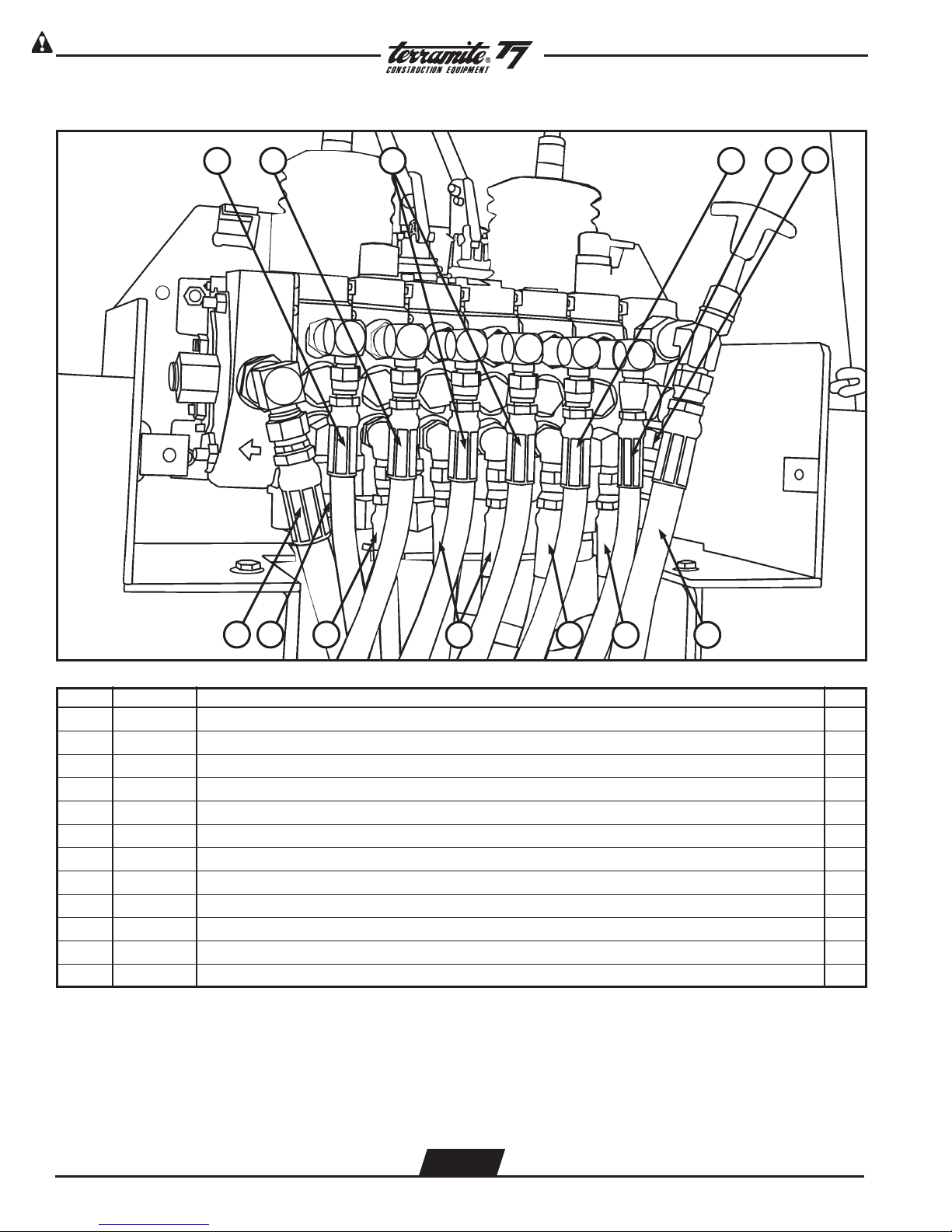
View of Hose Location for Rear Valve (180 Swing)
6
1 4
2 3
5
1112
ITEM PART NUMBER DESCRIPTION QTY.
10
9
4
78
1 80202 Hose, 1/4" x 130" 1
2 80203 Hose, 1/4" x 91" 1
3 80188 Hose, 1/4" x 48" 2
4 80205 Hose, 1/4" x 67" 2
5 80190 Hose, 1/4" x 25" 1
6 80200 Hose, 1/2" x 47" 1
7 80201 Hose, 1/2" x 57" 1
8 80197 Hose, 1/4" x 24" 1
9 80202 Hose, 1/4" x 39" 2
10 80204 Hose, 1/4" x 87" 1
11 80191 Hose, 1/4" x 124" 1
12 80199 Hose, 1/2" x 180" 1
WWW.TERRAMITE.COM
Charleston, WV/USA
2.42
USA 1.800.428.3772
Intl. 1 .304.776.4231
Page 49

View of Right Rear Tire and Rim
Read Operators Manual For SafetyPARTS MANUAL
Copyright © 2007 Terramite Corporation
6 Tire Tube
7 Tire Assembly
ITEM PART NUMBER DESCRIPTION QTY.
5
4
3
12
1 51173 Tire, Rear, High Flotation, 31” x 15.5” x 15”, T5C/T5D/T6/T7/T9 1
2 50016 Rim, Rear, 15” x 13”, T5C/T5D/T6/T7/T9 1
3 51003 Valve Stem 1
4 28506 Nut Lug, 1/2” - 20 ID x 13/16” OD, Front & Rear 5
5 55380 Lug Stud, Rear Wheel 5
6 51000 Tube, 9.50 x 16 Tire (Not Shown) 1
7 51018 Assembly, Tire & Rim, Rear - HFT, T5C/T5D/T6/T7/T9 1
WWW.TERRAMITE.COM
Charleston, WV/USA
2.43
USA 1.800.428.3772
Intl. 1 .304.776.4231
Page 50
Read Operators Manual For Safety PARTS MANUAL
Copyright © 2007 Terramite Corporation
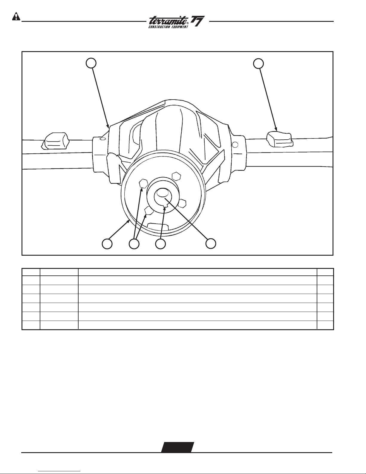
View from Front of Rear Axle
1
2
43
ITEM PART NUMBER DESCRIPTION QTY.
5
6
1 55004 Axle, Rear, T5C/T5D/T7/T9 2W 1
2 55005 Pad, Rear Axle Spring 2
3 57034 Brake Drum, Weldment 1
4 26288 Bolt, 3/8” x 1 3/4” NF GR8Z 4
5 62021 Key, Torque Motor, TRW/Parker 1
6 51800 Flange, Drive Motor, T4/T5C/T5D/T6/T7/T9 1
WWW.TERRAMITE.COM
Charleston, WV/USA
2.44
USA 1.800.428.3772
Intl. 1 .304.776.4231
Page 51

Top View of Parking Brake Assembly
Read Operators Manual For SafetyPARTS MANUAL
Copyright © 2007 Terramite Corporation
2
1 2
8
9
7
10
6
5 4 3
ITEM PART NUMBER DESCRIPTION QTY.
NOT SHOWN
ATTACHES TO BRAKE BAND
1 55620 Brake Band 1
2 55606 Brake Cable 1
3 55613 Brake Off Set Link Not Shown - Attaches to Brake Band 1
4 64003 Drive Motor 1
5 51800 Drive Motor Flange 1
6 22034 Bolt 1
7 28500 Nut 1
8 23005 Nut 1
9 22038 Bolt 1
17028 Bushing, Brake 9/16" ID x 1" OD x 7/8" L 1
10 17029 Bushing, Brake 9/16" ID x 1"OD x 1 1/4" L 1
22042 Bolt, 14mm x 90 mm C2.0z Brake 38748 1
ITEM
SHOWN
ITEM
SHOWN
13168 Spring, Retro Fit Parking Brake 1
55621 Spring Bracket, Parking Brake 1
WWW.TERRAMITE.COM
Charleston, WV/USA
2.45
USA 1.800.428.3772
Intl. 1 .304.776.4231
Page 52
Read Operators Manual For Safety PARTS MANUAL
Copyright © 2007 Terramite Corporation
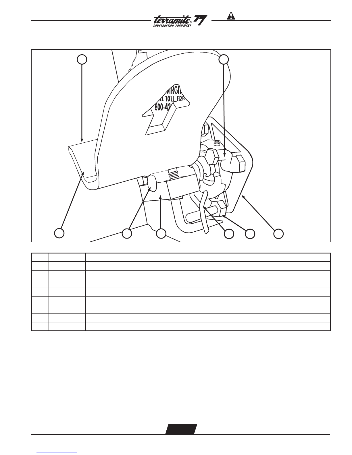
View from Left Side of Outrigger Assembly (Curved Boom)
1 2 3 4
5
7
ITEM PART NUMBER DESCRIPTION QTY.
6
1 81139 Cylinder, Outrigger, T5C/T5D/T7 1
2 11123 Guard, Outrigger, T5C/T5D/T7 1
3 11502 Pin, 4 1/8”, Outrigger to Cylinder, T5C/T5D/T6/T7/T9 1
4 10202 Pin, Linch (Not Shown) 1
5 11048 Pad, Outrigger Foot 1
6 17156 Pin, 5 1/4”, Pull, Outrigger Pad, T5D/T6/T7/T9 1
7 11112 Outrigger, T5C/T5D/T7 1
WWW.TERRAMITE.COM
Charleston, WV/USA
2.46
USA 1.800.428.3772
Intl. 1 .304.776.4231
Page 53

Read Operators Manual For SafetyPARTS MANUAL
Copyright © 2007 Terramite Corporation
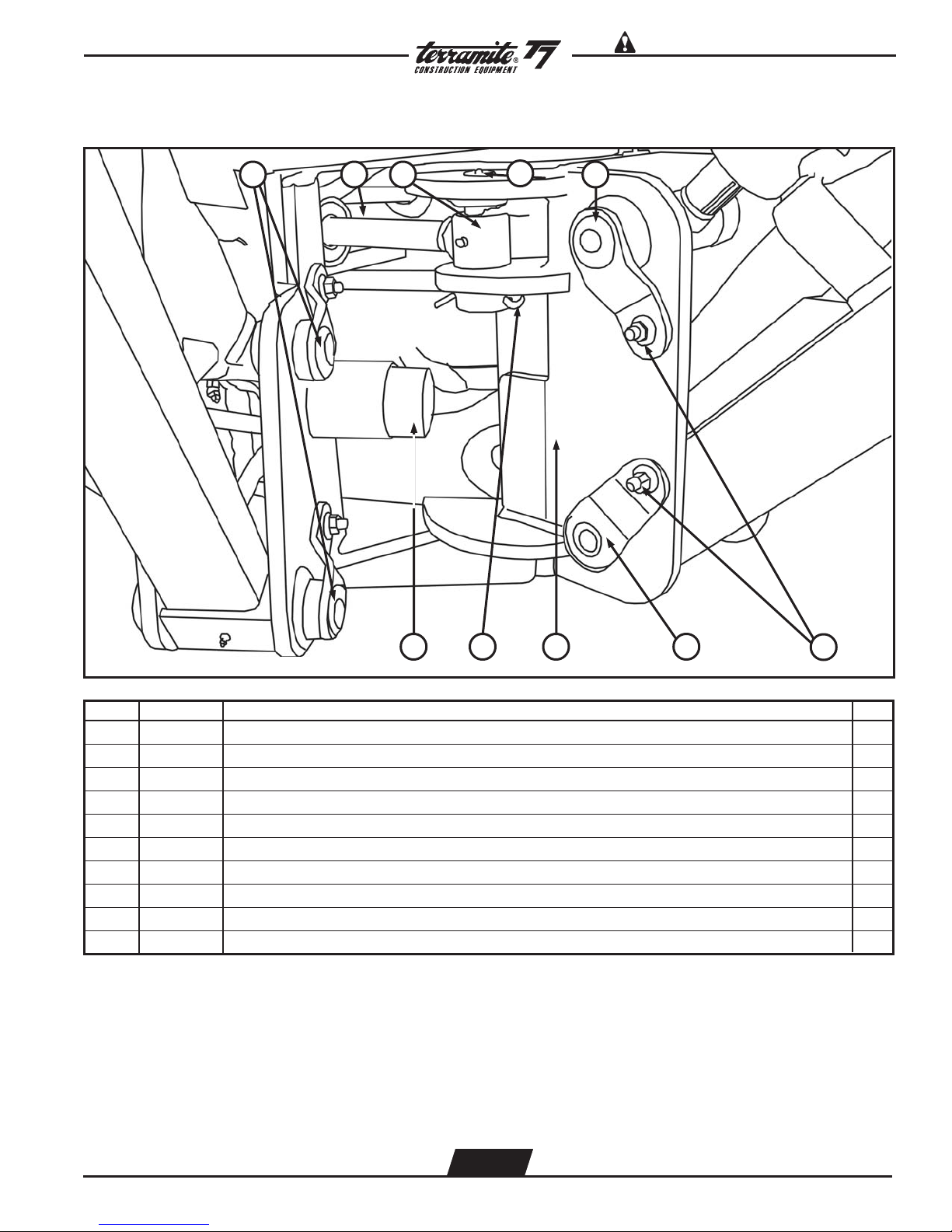
View of Left Side of Swing Assembly (Curved Boom Prior 1-1-01)
1
2
5
8
7
6
3
9 10 9
4
11
12
ITEM PART NUMBER DESCRIPTION QTY.
14
13 12
1 15300 Pin, 4 1/8”, Swing Cylinder to Swing, T5C/T5D/T6/T7/T9 (Not Shown) 1
2 11140 Pin, 18”, Swing Pin, T5C/T5D/T7 (Not Shown) 1
3 17208 Pin, 7 3/4”, Boom Cylinder to Swing, T6/T7/T9 1
4 10237 Boom Latch, Curved Boom, T5D/T6/T7/T9 1
5 10400 Pin, 8 1/4”, Boom to Swing, T5C/T5D/T7 1
6 21420 Pin, Cotter, Case Hard 1
7 11006 Stop, Swing, T5C/T5D/T7 1
8 11100 Pin, 6 1/4”, Outrigger, Boom, T5C/T5D/T6/T7/T9 1
INSET - SWING CYLINDER SUB - ASSEMBLY
9 20025 Fitting, 1/4” Tee 2
10 80045 Hose, 1/4” Swing Crossover, 15” 2
11 82070 Cylinder, Swing w/Tee Fitting 2
12 20174 Fitting, 1/4”M x 1/4”FM Straight, Swivel 2
13 88420 Hose, 1/4” Swing to Valve, 20” 1
14 88425 Hose, 1/4” Swing to Valve, 25” 1
WWW.TERRAMITE.COM
Charleston, WV/USA
2.47
USA 1.800.428.3772
Intl. 1 .304.776.4231
Page 54

Read Operators Manual For Safety PARTS MANUAL
Copyright © 2007 Terramite Corporation
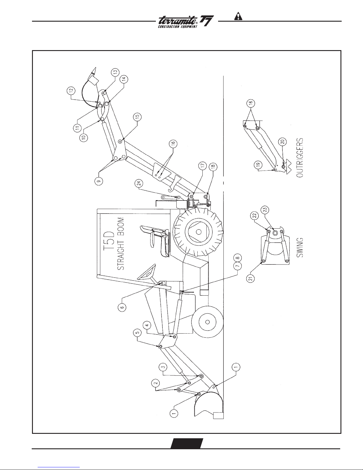
View of Backhoe Assembly for T5D with Straight Boom
1 2 3 4 5 6
7
8
9101112
ITEM PART NUMBER DESCRIPTION QTY.
1 10184 Boom Lock, T5C/T5D 1
2 13114 Spring, Boom Lock, 5.5”L 1
3 10193 Handle, Boom Lock, T5C/T5D 1
4 13942 Knob, Red 1
5 21000 Cylinder,Crowd, T5/T5C/T5D 1
6 81060 Cylinder, Rear Curl,T5C/T5D 1
7 10322 Assembly, Dipper, T5D (Includes Decals) 1
8 10289 Assembly, Boom, T5D (Includes Decals) 1
9 21200 Cylinder, Boom, T5/T5C/T5D 1
10 11501 Outrigger, T5C/T5D 2
11 11123 Guard, Outrigger, T5C/T5D/T7 2
12 81139 Cylinder, Outrigger, T5C/T5D/T7 2
WWW.TERRAMITE.COM
Charleston, WV/USA
2.48
USA 1.800.428.3772
Intl. 1 .304.776.4231
Page 55
Read Operators Manual For SafetyPARTS MANUAL
View from Right Side of Swing Assembly (Straight Boom)
Copyright © 2007 Terramite Corporation
21
3 5
4
78910
ITEM PART NUMBER DESCRIPTION QTY.
6
1 11100 Pin, 6 1/4” Outrigger, Boom, T5C/T5D/T6/T7/T9 2
2 25201 Rod, Swing, T5C/T5D/T6/T7/T9 1
3 82070 Cylinder, Swing, T5C/T5D/T6/T7/T9 1
4 15300 Pin, 4 1/8”, Swing Cylinder to Swing, T5C/T5D/T6/T7/T9 2
5 10410 Pin, 7 3/4”, Boom Cylinder to Swing, T5C/T5D/T6/T7 1
6 20082 Nut, 3/8"NC Flange Z 2
7 10400 Pin, 8 1/4”, Dipper/Bucket, Boom/Swing, T5C/T5D/T6/T7 1
8 11300 Swing, T5C/T5D 1
9 21420 Pin, Cotter, Case Hard 1
10 11006 Stop, Plastic, Swing, T5C/T5D/T7 1
WWW.TERRAMITE.COM
Charleston, WV/USA
2.49
USA 1.800.428.3772
Intl. 1 .304.776.4231
Page 56
Read Operators Manual For Safety PARTS MANUAL
Copyright © 2007 Terramite Corporation
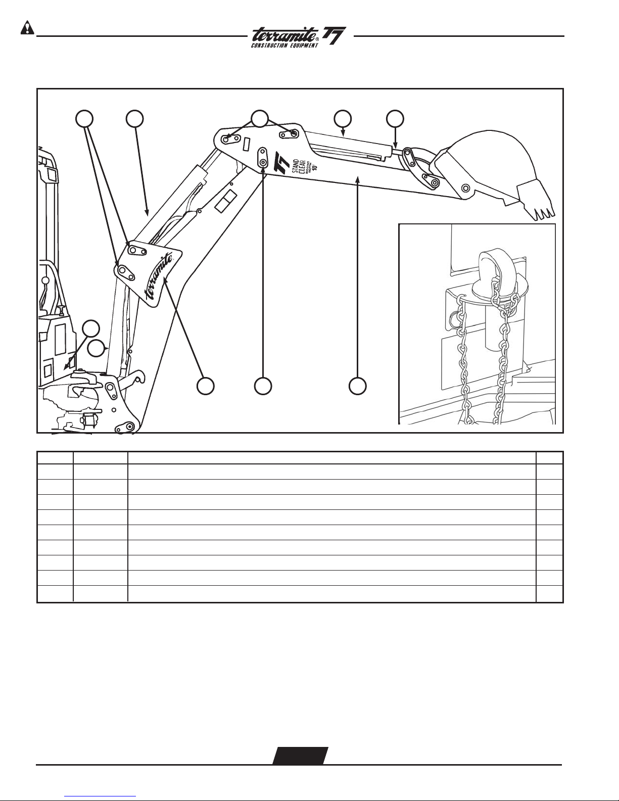
View of Left Side of Backhoe Assembly (Prior 1-1-01)
2
9
8
1 2 3 4
9
567
ITEM PART NUMBER DESCRIPTION QTY.
1 81190 Cylinder, Boom and Crowd, T7 2
2 10700 Pin, 6 7/8”, Crowd and Rear Curl Cylinder, Dipper, T5C/T5D/T7 4
3 81158 Cylinder, Rear Curl, T5D/T7 1
4 81048 Rod, Rear Curl, T5D/T7 1
5 10271 Assembly, Dipper, T7 (Includes Decals) 1
6 10701 Pin, 7 1/4”, Boom to Dipper, T5C/T5D/T7 1
7 10292 Assembly, Boom, Curved, T5D/T7 (Includes Decals) 1
8 81222 Cylinder, Boom, T7 1
9 17270 Pin, Lock, Swing, T7/9 1800 1
WWW.TERRAMITE.COM
Charleston, WV/USA
2.50
USA 1.800.428.3772
Intl. 1 .304.776.4231
Page 57

Read Operators Manual For SafetyPARTS MANUAL
View of Left Side of Rear Bucket & Linkage Assembly
Copyright © 2007 Terramite Corporation
1 2
3 4
5
ITEM PART NUMBER DESCRIPTION QTY.
6 7 8 9 10 11 12 13 14 15
1 17190 Pin, 8 1/4”, Quick Attach Bucket, T5C/T5D/T7 1
2 10812 Pin, 7 5/8”, Dipstick to Linkage, T5C/T5D/T6/T7/T9 1
3 20082 Nut, 3/8” NC Flange Z 2
4 11160 Bucket, 16”, Quick Attach, T5C/T5D/T7 1
5 19479 Center Assembly, Quick Attach, T5C/T5D/T7 1
6 17269 Pin, 6 1/2”, Rear Curl Cylinder to Quck Attach, T5C/T5D/T6/T7/T9 1
7 10812 Pin, 7 5/8”, Dipstick to Linkage, T5C/T5D/T6/T7/T9 1
8 10202 Pin, Linch, T5C/T5D/T6/T7/T9/Sweeper 1
9 17273 Pin, 9”, Quick Attach Pull, T5C/T5D/T7 1
10 18240 Linkage Assembly, Center, T5C/T5D/T6/T7/T9 1
11 10260 Bushing, 1 1/2” ID x 1 3/4”OD x 3” L 1
12 10819 Bushing 1 ID” x 1 1/4” OD x 1” L 1
13 17055 Bushing, 1 1/2” ID x 1 3/4” OD x 2” L 1
14 18261 Linkage Link, Right, T5C/T5D/T6/T7/T9 1
15 18260 Linkage Link, Left, T5C/T5D/T6/T7/T9 1
WWW.TERRAMITE.COM
Charleston, WV/USA
2.51
USA 1.800.428.3772
Intl. 1 .304.776.4231
Page 58
Read Operators Manual For Safety PARTS MANUAL
Copyright © 2007 Terramite Corporation
T7 Backhoe Assembly 180
33
39
38
36
35
37
34
o
4
2
46
45
5
3
44
1
5
18
20
32
2
7
18
13
12
14 17 10 6
16
41
40
13
15
14
44
45
43
42
6
47
9
19
11
5
8
WWW.TERRAMITE.COM
Charleston, WV/USA
2.52
USA 1.800.428.3772
Intl. 1 .304.776.4231
Page 59

Read Operators Manual For SafetyPARTS MANUAL
Copyright © 2007 Terramite Corporation
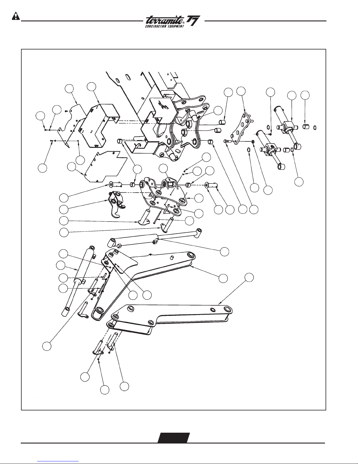
T7 Backhoe Assembly 180
ITEM PART NUMBER DESCRIPTION QTY.
1 11150 Swing, 180, T7/T9 1
o
o
2 17055 Bushing, 1.5"ID x 1.75"OD x 2"L 4
3 17244 Pin, 51/2”, Swing Cylinder 2
4 11155 Plate, Swing Cylinder, 180, T7/T9 1
o
5 17252 Bushing, 1.5"ID x 1.75"OD x 1.25"L, T7/T9 6
6 17253 Pin, 4 3/4”, Swing Pivot, 180, T7/T9 2
7 81169 Cylinder, Trunnion Swing, 180, T7/T9 2
o
o
8 21420 Pin, Cotter, Case Hard 2
9 10292 Assembly, Boom, T7 (Includes Decals) 1
10 10237 Boom Latch, Curved Boom, T5D/T6/T7/T9 1
11 10271 Assembly, Dipper, T7 (Includes Decals) 1
12 81190 Cylinder, Crowd, T7 1
13 10700 Pin, 6 7/8” Crowd & Rear Curl Cylinder, T5C/T6/T7/T9 3
14 10406 Pin, 7 1/4” Boom to Dipper, T5B/T5D/T6/T7/T9 2
15 20082 Nut, 3/8" NC Flange Z 6
16 22123 Bolt, 3/8-16 x 1 1/4" Gr8 Z 6
17 17208 Pin, 8 1/4” Boom Cylinder to Swing, T6/T7/T9 1
18 22200 Ring, External, Snap, 11/2", 180, T7/T9 4
o
19 22197 Bolt, 3/4-16 x 2 3/4" Gr8 Z 4
20 22199 Nut, 3/4-16, Nylon Lock Gr8 Z 4
21 15138 Bracket, Engine Mounting, Front, Perkins, 20hp. 1
22 15136 Bracket, Engine Mounting, Rear, Perkins, 20hp. 2
23 48024 Mount, Rubber Isolator 4
24 22021 Bolt, 1/2-13 x 3" NC Gr8 Z 4
25 22081 Washer, 1/2" USS 4
26 22080 Washer, 1/2" x 2" OD Z 4
27 28500 Nut, 1/2" NC Lock Z 4
28 24007 Spacer, Frame, Front Valve Washer 4
29 10062 Bracket, Radiator Arm (Left) Perkins 1
30 10063 Bracket, Radiator Arm (Right) Perkins 1
31 22008 Bolt, 3/8-16 x 1" Gr 8 ZP, T5C/T5D/T6/T7/T9/Sweeper 4
32 20134 Fitting, #6 O-ring Plug 2
33 16279 Cover, Rear Valve, V-10, 180, T7/T9 1
o
34 15147 Plate, Back Valve Cover, V-10 6 Spool 1
35 15148 Plate, Top Valve Cover, V-10 6 Spool 1
36 22025 Bolt, 1/4" x 3/4" NC Gr8, T5C/T5D/T6/T7/T9/Sweeper 3
37 24008 Washer, 1/4" Flat USS 13
38 22045 Bolt, 5/16" x 3/4" NC Gr8 Z 7
39 28504 Nut, 1/4" NC Lock Z 3
40 22212 Bolt, 5/16" NC x 4 1/2" L, Gr8 Z 3
41 17257 Spacer, Boom Hose 3
42 17258 Spacer, Swing Hose Guide 1
43 22213 Bolt, 5/16" NC x 7" L, Gr 8 Z 1
44 28020 Washer, 5/16", Lock Z 4
45 23003 Nut, 5/16-18, Hex NC 4
46 17256 Stop, Plastic Swing 2
47 81222 Cylinder, Boom, T7 1
WWW.TERRAMITE.COM
Charleston, WV/USA
2.53
USA 1.800.428.3772
Intl. 1 .304.776.4231
Page 60

Read Operators Manual For Safety PARTS MANUAL
Copyright © 2007 Terramite Corporation
Tooth Caps
4
1
ITEM PART NUMBER DESCRIPTION QTY.
2 3
1 10500 Cap, Tooth, Standard Pin, T5C/T5D/T6/T7/T9 NA
2 10590 Cap, Tooth, Tiger NA
3 10591 Cap, Tooth, Tiger, HD NA
4 10530 Roll Pin, Tooth Cap, SD NA
ROLL PIN
Not Shown
Position machine must be in to check proper level in hydraulic tank.
NOTE: Filling tank with loader or backhoe in any other position will result in overfilling and spillage of fluid
through the breather cap. Replace cap if oil should ever spill out of breather cap since it will clog off
the air supply that the systems needs to operate properly.
Loader arm lifted off ground a few inches. Backhoe dipper fully extended
Front loader bucket curled back Backhoe Bucket curled all the way back
Backhoe boom in full raised position
WWW.TERRAMITE.COM
Charleston, WV/USA
2.54
USA 1.800.428.3772
Intl. 1 .304.776.4231
Page 61

Read Operators Manual For SafetyPARTS MANUAL
Copyright © 2007 Terramite Corporation
Hydraulic System Oil Change and Type Specifications
When your machine is new, the hydraulic system oil and filter should be changed within the first 50
hours of use and every 250 thereafter. Refill the hydraulic reservoir with engine oil type API SF.CD
15W40 when outside temperature is above 40 degrees F. Use engine oil type API SF.CD 10 weight
when outside temperature is below 40 degrees F. Replace filter with Terramite / 2-200.5C filter or
NAPA / 1759 filter. It is important to follow these instructions to alleviate any cold weather engine
starting problems and any pressure or heat related component failure.
DO NOT USE HYDRAULIC OIL!
MAJOR DAMAGE WILL RESULT!
For your engine oil requirements and change intervals refer to your engine owners manual.
On Hand Spare Parts
Following is a list of spare parts we recommend you keep on hand.
Oil, Fuel and Air Filters
One of each size Cylinder Packing Kit (specify serial number of machine when ordering)
Grease Fittings
One each of a longest length and medium length Hoses and spare Cylinder Fittings
Tie Rod End
Pedal Return Spring
Wheel Bearings
Tooth Caps with Pins
Assortment of long, medium and short Pins
Control Valve Linkage Parts and Cotter Pins
Special Tools
ITEM PART NUMBER DESCRIPTION QTY.
1 10599 1-05.SDT Punch, for 1-05.SD & TT Tooth Caps 1
2 21176 A-176 Spanner wrench for cylinder repair 1
WWW.TERRAMITE.COM
Charleston, WV/USA
2.55
USA 1.800.428.3772
Intl. 1 .304.776.4231
Page 62
Read Operators Manual For Safety PARTS MANUAL
Copyright © 2007 Terramite Corporation
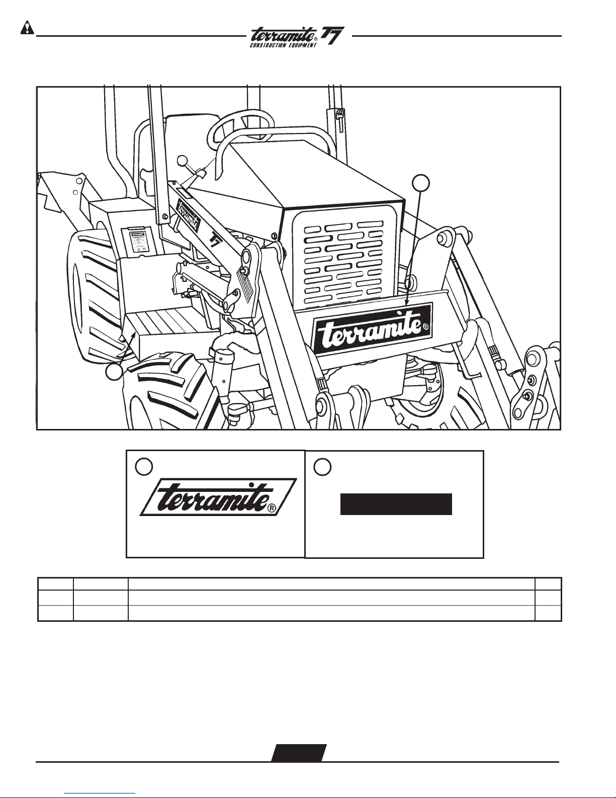
Decal Location - Front Arms
1
2
1
ITEM PART NUMBER DESCRIPTION QTY.
2
1 14194 Decal, Black, TMC Jumbo Logo, T6/T7/T9/Sweeper 1
2 16181 Kit, Complete, Skid Tape, T5D/T7/T9/T6 2
WWW.TERRAMITE.COM
Charleston, WV/USA
3.1
USA 1.800.428.3772
Intl. 1 .304.776.4231
Page 63
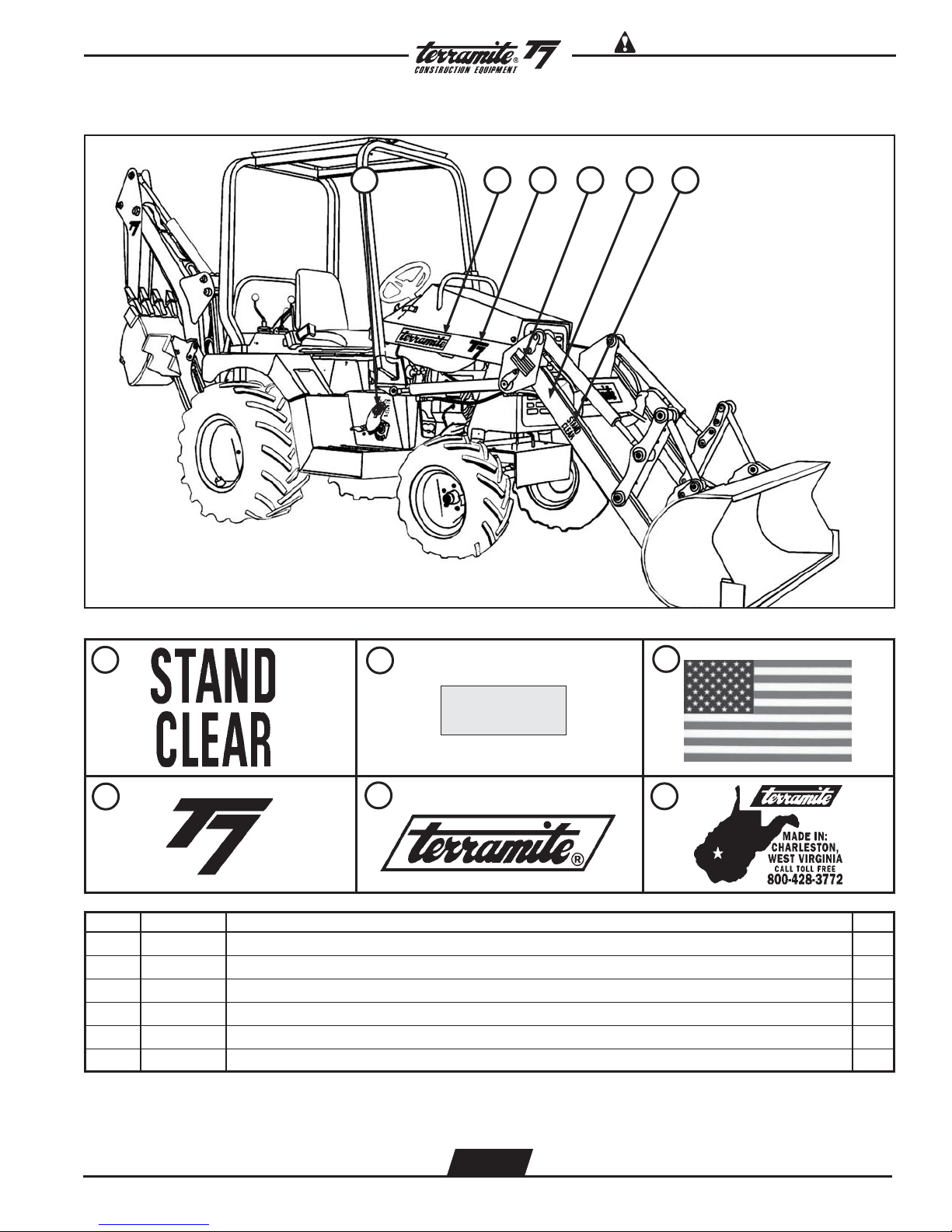
Decal Location - Side View
Read Operators Manual For SafetyPARTS MANUAL
Copyright © 2007 Terramite Corporation
123456
1
4
ITEM PART NUMBER DESCRIPTION QTY.
2
5
3
6
1 14004 Decal, Stand Clear, Red, T5C/T5D/T6/T7/T9 4
2 14021 Decal, Reflector, Amber, T5C/T5D/T6/T7/T9 2
3 14099 Decal, American Flag, T5C/T5D/T6/T7/T9 2
4 14001 Decal, Terramite, Large, T5C/T5D/T6/T7/T9 2
5 14214 Decal, Black, Small, T7 2
6 14070 Decal, Black, W.V., T5C/T5D/T6/T7/T9/Sweeper 2
WWW.TERRAMITE.COM
Charleston, WV/USA
3.2
USA 1.800.428.3772
Intl. 1 .304.776.4231
Page 64
Read Operators Manual For Safety PARTS MANUAL
Copyright © 2007 Terramite Corporation
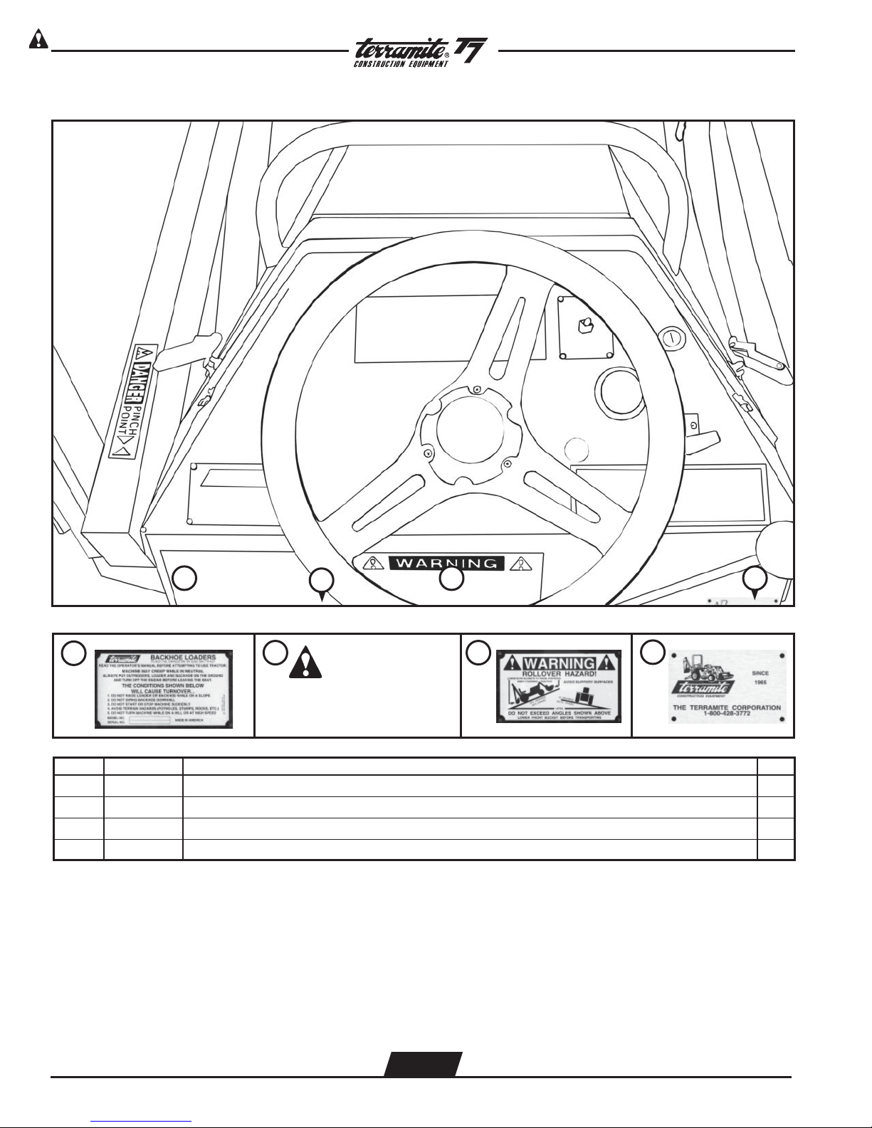
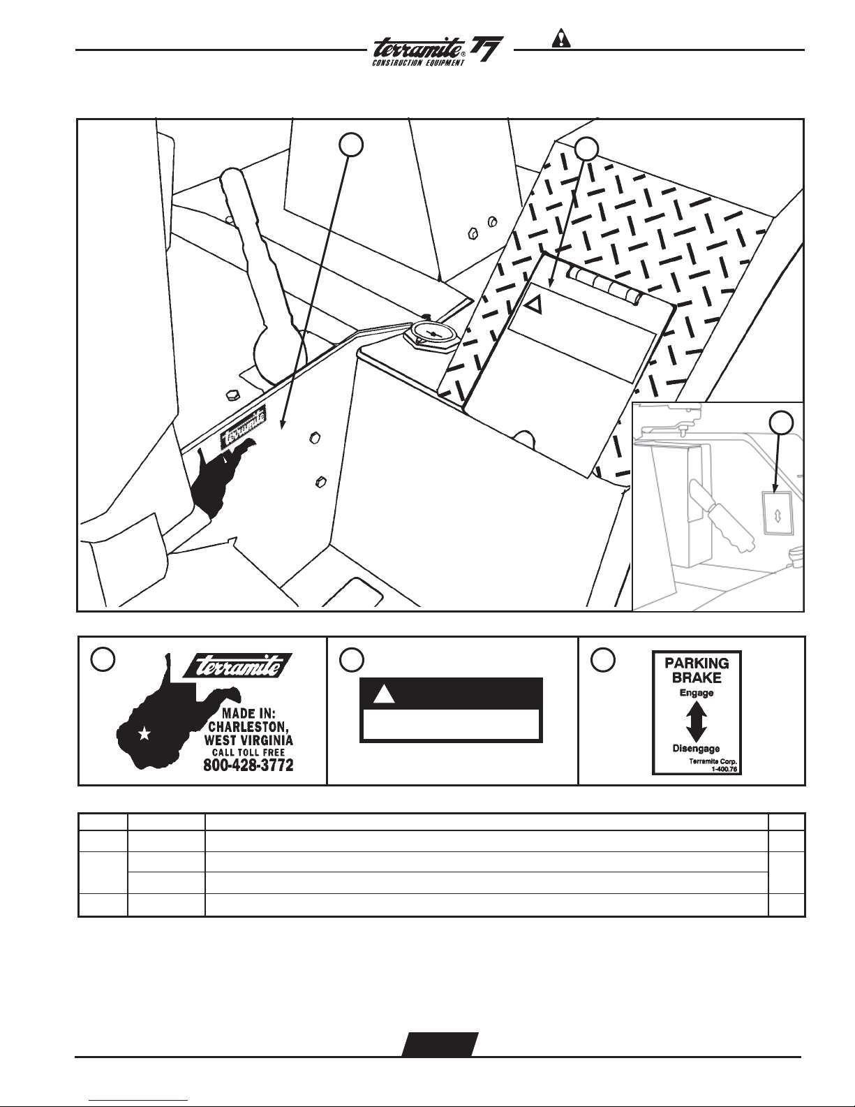
Decal Location - Dash
2
1
ITEM PART NUMBER DESCRIPTION QTY.
1 14203 Decal, Read Operators Manual, T5D/T6/T7/T9 1
2 14220 Decal, Danger, Parking Brake - NIU 1
3 14202 Decal, Warning Roll Over, T5D/T6/T7/T9 1
4 14024 Decal, Plate, TMC Starting 1965 1
2 3
DD
ANGERANGER
D
ANGER
DD
ANGERANGER
SET PARKING BRAKE
AND LOWER BUCKETS TO
GROUND WHEN MACHINE
IS NOT IN USE.
31
4
4
WWW.TERRAMITE.COM
Charleston, WV/USA
3.3
USA 1.800.428.3772
Intl. 1 .304.776.4231
Page 65

Decal Location - Dash (Diesel Shown)
1 2 3 4 5
Read Operators Manual For SafetyPARTS MANUAL
Copyright © 2007 Terramite Corporation
67
1
DANGER
Front Work Lights
4
PINCH
POINT
5
MODEL NO.
SERIAL NO.
CHARLESTON, WV 25313 1-304-776-4231
MADE IN USA
6 7
KEEP SHIELDS, GUARDS AND SFETY DEVICES IN PLACE
KEEP HANDS AND FEET FROM MOVING PARTS
NEVER LET CHILDREN RIDE ON OR OPERATE THE TRACTOR
BE ALERT FOR DANGER TO BYSTANDERS AND PROPERTY
HANDLE FUEL WITH CARE AND USE APPROVED CONTAINERS
KEEP MACHINE LUBRICATED AND IN A GOOD STATE OF REPAIR
SAFETY FIRST
PN/ 14201
Throttle
Rear Work Lights
ITEM PART NUMBER DESCRIPTION QTY.
1 14100 Decal, Pinch Point, T5C/T5D/T6/T7/T7/T9 2
2 14012 Decal, Serial Number Plate, T5D/T7/T9/SCR/Sweeper/Dozer 1
3 14201 Decal, Safety First, T5D/G/T6/T7/T9 1
4 14104 Decal, Work Lights, Plate F&R, T5D/T6/T7/T9 1
5 14105 Decal, Throttle Plate, T5D/T6/T7/T9 1
6 14053 Decal, Call Before U Dig 1
7 14204 Decal, Controls, Front Bucket, T5D/T6/T7/T9 1
WWW.TERRAMITE.COM
Charleston, WV/USA
3.4
USA 1.800.428.3772
Intl. 1 .304.776.4231
Page 66
Read Operators Manual For Safety PARTS MANUAL
Copyright © 2007 Terramite Corporation
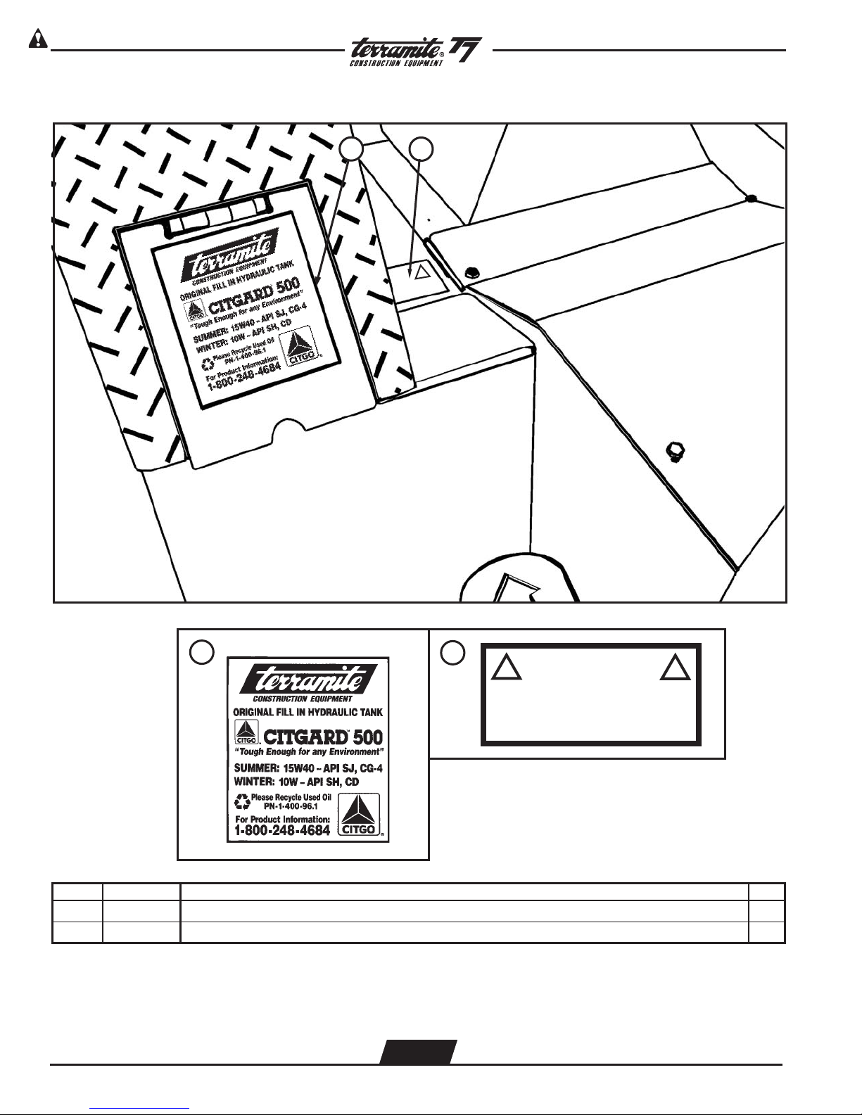
Decal Location - Right Fender
1
2
!
1
ITEM PART NUMBER DESCRIPTION QTY.
2
CAUTION
!
Regular hydraulic fluid in this system
will cause premature transmission failure.
Above 32 F use 15w40 API SG CD or equivalent.
Below 32 F use 10w API SG CD
!
Terramite Corp. PN
1-400-98
1 14017 Decal, Oil, Citgo/Terramite, T5C/T5D/T6/T7/T9 1
2 14098 Decal, Caution, Hydraulic Premature Failure, T5C/T5D/T6/T7/T9 2WD 1
WWW.TERRAMITE.COM
Charleston, WV/USA
3.5
USA 1.800.428.3772
Intl. 1 .304.776.4231
Page 67
Decal Location - Left Fender
Read Operators Manual For SafetyPARTS MANUAL
Copyright © 2007 Terramite Corporation
1
2
!
3
1
ITEM PART NUMBER DESCRIPTION QTY.
2
!
DANGER
DIESEL FUEL ONLY
NO SMOKING NO OPEN FLAMES
3
1 14070 Decal, Black, W.V., T5C/T5D/T6/T7/T9/Sweeper 1
2
14071 Decal, Diesel Fuel Only, T5C/T5D/T6/T7/T9
14051 Decal, Gasoline Only, T5C/T5D/T7
3 14076 Decal, Parking Brake 1
WWW.TERRAMITE.COM
Charleston, WV/USA
3.6
USA 1.800.428.3772
Intl. 1 .304.776.4231
1
Page 68
Read Operators Manual For Safety PARTS MANUAL
Copyright © 2007 Terramite Corporation
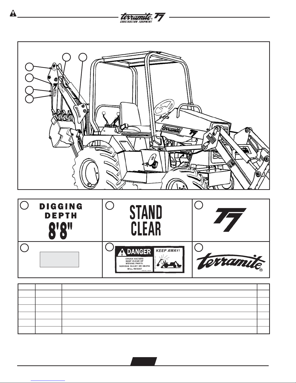
Decal Location Side View (continued)
5
4
3
2
1
6
1
4
ITEM PART NUMBER DESCRIPTION QTY.
2
5
PN/ 14054
3
6
1 14093 Decal, Digging Depth 8'8", T5D/T7 2
2 14004 Decal, Stand Clear Red, T5C/T5D/T6/T7/T9 4
3 14159 Decal, Black, Large, T7 2
4 14022 Decal, Reflector, Red, T5C/T5D/T6/T7/T9 2
5 14054 Decal, Warning, Crush Hazard, T5C/T5D/T6/T7/T9 2
6 14107 Decal, Black, Radius, Terramite, T6/T9 2
WWW.TERRAMITE.COM
Charleston, WV/USA
3.7
USA 1.800.428.3772
Intl. 1 .304.776.4231
Page 69

Decal Location - Rear Valve
Read Operators Manual For SafetyPARTS MANUAL
Copyright © 2007 Terramite Corporation
1
2
3
1
2
READ
OWNER’S
MANUAL
BEFORE
OPERATING
ITEM PART NUMBER DESCRIPTION QTY.
3
BOOM LATCH
TO ENGAGE
BOOM LATCH
1. Raise boom to
full UP position
2. Using control
cable, lower boom
latch onto pins
3. Lower boom
to lock position
TO DISENGAGE
BOOM LATCH
1. Raise boom to
full UP position
2. Pull handle and
turn clockwise
to lock boom latch
in disengaged
position
3. Operate backhoe
TMC P/N 14112
1 14284 Decal, Operator Danger T7/T9 1
2 14207 Decal, Vertical, Read Owners Manual, T5C/T5D/T6/T7/T9 1
3 14112 Decal, Boom Latch Operator, T7/T9 1
WWW.TERRAMITE.COM
Charleston, WV/USA
3.8
USA 1.800.428.3772
Intl. 1 .304.776.4231
Page 70
Read Operators Manual For Safety PARTS MANUAL
Copyright © 2007 Terramite Corporation
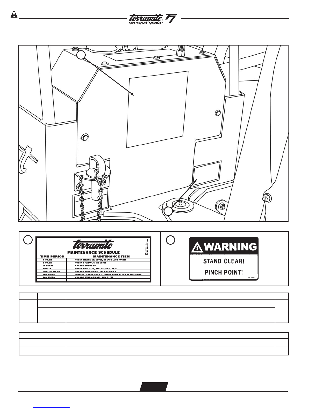
Decal Location - Rear Valve (Continued)
1
2
1
ITEM PART NUMBER DESCRIPTION QTY.
1
14510 Decal, Maintenance Diesel Only
14005 Decal, Maintenance Gas Only
2
2 38186 Decal, Pinch Point, Stand Clear, T7/T9/Sweeper 2
PAINT
08026 Paint, Yellow, Spray Can Dupont Paint Code #G 9325A 1
08037 Paint, Gray, Spray Can 1
1
WWW.TERRAMITE.COM
Charleston, WV/USA
3.9
USA 1.800.428.3772
Intl. 1 .304.776.4231
Page 71
T5D/T7 Pin Chart (Straight Boom)
Read Operators Manual For SafetyPARTS MANUAL
Copyright © 2007 Terramite Corporation
WWW.TERRAMITE.COM
Charleston, WV/USA
4.1
USA 1.800.428.3772
Intl. 1 .304.776.4231
Page 72

Read Operators Manual For Safety PARTS MANUAL
Copyright © 2007 Terramite Corporation
T5D/T7 Pin Chart (Straight Boom)
T5D PINS
ITEM P/N DESCRIPTION SIZE
1 13200 FRONT BUCKET/ARMS 1” x 4 3/4”
2 17176 ARM LINK/ARM CYLINDER 1” x 5 1/2”
3 17178 ARM LINK/ARM - TAPPED 1” x 5 1/2”
4 17179 ARM BUCKET/FRONT CURL 1” x 5 1/2”
5 12600 ARM CYLINDER/ARMS 1” x 5 1/4”
6 12300 ARM/FRAME 1” x 6 7/8”
7 12301 ARM CYLINDER/FRAME 1” x 7 7/8”
8 17198 ARM/CYLINDER/FRAME 1” x 8 1/2”
9 10700 CROWD & REAR CURL CYLINDER/DIPPER 1” x 6 7/8”
10 17031 LINKAGE CURL/CYLINDER 1” x 7 3/8”
11 10206 R.C. CYLINDER/BUCKET Q.D. & BOOM LATCH 1” x 6 1/2”
12 19072 REAR BUCKET PULL 1” x 8 1/2”
13 17190 Q.A. BUCKET 1 1/4” x 8 1/4”
14 10812 DIP/LINKAGE 1 1/4” x 7 5/8”
15 10701 BOOM/DIPPER 1 1/4” x 7 1/4”
16 11100 CRD-BM CYL/BM,O.R/FRAME 1” x 6 1/4”
17 10410 BOOM CYL./SWING 1 1/4” x 7 3/4”
18 10400 DIP/BKT,BOOM/SWING 11/4” x 8 1/4”
19 11502 OUTRIGGERS 1” x 4 1/8”
20 17156 OUTRIGGER PAD - PULL PIN 1” x 5 1/4”
21 17020 SWING CYL/FRAME 1” x 6 5/8”
22 15300 SWING CYL/SWING 1” x 4 1/8”
23 11140 SWING 1 1/4” x 18”
24 17174 BOOM LOCK 1 1/4” x 11”
WWW.TERRAMITE.COM
Charleston, WV/USA
4.2
USA 1.800.428.3772
Intl. 1 .304.776.4231
Page 73

T7 Pin Chart (Curved Boom Prior 1/1/01)
Read Operators Manual For SafetyPARTS MANUAL
Copyright © 2007 Terramite Corporation
WWW.TERRAMITE.COM
Charleston, WV/USA
4.3
USA 1.800.428.3772
Intl. 1 .304.776.4231
Page 74

Read Operators Manual For Safety PARTS MANUAL
Copyright © 2007 Terramite Corporation
T7 Pin Chart (Curved Boom Prior 1/1/01)
T7 CURVED BOOM PINS
ITEM P/N DESCRIPTION SIZE
1 13200 FRONT BUCKET/ARMS 1” x 4 3/4”
2 17176 ARM LINK/ARM CYLINDER 1” x 5 1/2”
3 17178 ARM LINK/ARM - TAPPED 1” x 5 1/2”
4 17179 ARM BUCKET/FRONT CURL 1” x 5 1/2”
5 12600 ARM CYLINDER/ARMS 1” x 5 1/4”
6 12300 ARM/FRAME 1” x 6 7/8”
7 12301 ARM CYLINDER/FRAME 1” x 7 7/8”
8 17198 ARM/CYLINDER/FRAME 1” x 8 1/2”
9 10700 CROWD & REAR CURL CYLINDER/DIPPER 1” x 6 7/8”
10 17031 LINKAGE CURL/CYLINDER 1” x 7 3/8”
11 10206 R.C. CYLINDER/BUCKET Q.D. & BOOM LATCH 1” x 6 1/2”
12 19072 REAR BUCKET PULL 1” x 8 1/2”
13 17190 Q.A. BUCKET 1 1/4” x 8 1/4”
14 10812 DIP/LINKAGE 1 1/4” x 7 5/8”
15 10701 BOOM/DIPPER 1 1/4” x 7 1/4”
16 10416 BOOM CYL./SWING 1 1/4” x 7 3/4”
17 10400 BOOM/SWING 1 1/4” x 8 1/4”
18 11100 CRD-BM CYL/BM,O.R/FRAME 1" x 6 1/4"
19 11502 OUTRIGGERS 1” x 4 1/8”
20 17156 OUTRIGGER PAD - PULL PIN 1” x 5 1/4”
21 17020 SWING CYL/FRAME 1” x 6 5/8”
22 15300 SWING CYL/FRAME 1” x 4 1/8”
23 11140 SWING 1 1/4” x 18”
WWW.TERRAMITE.COM
Charleston, WV/USA
4.4
USA 1.800.428.3772
Intl. 1 .304.776.4231
Page 75
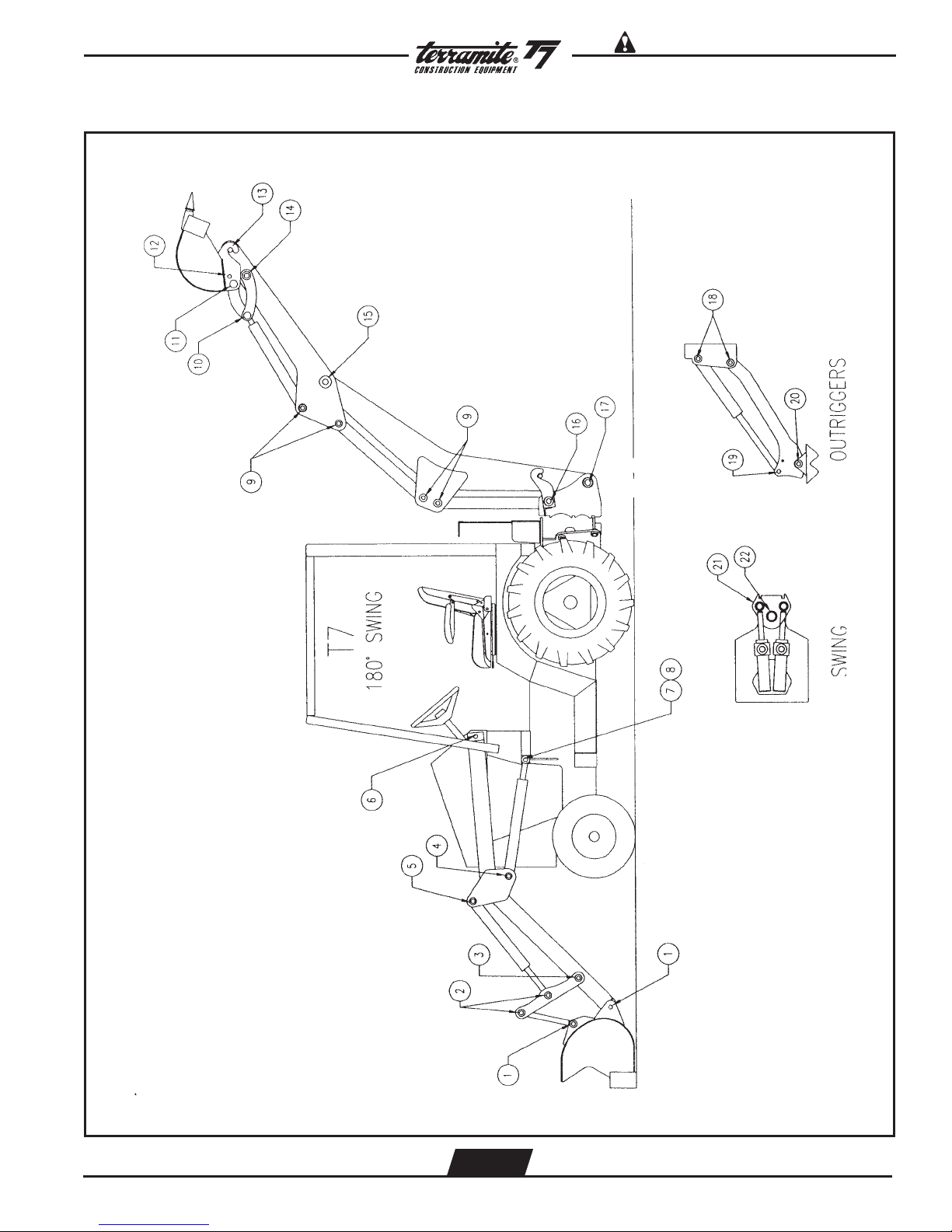
T7 Pin Chart (180 Degree Boom)
Read Operators Manual For SafetyPARTS MANUAL
Copyright © 2007 Terramite Corporation
WWW.TERRAMITE.COM
Charleston, WV/USA
4.5
USA 1.800.428.3772
Intl. 1 .304.776.4231
Page 76

Read Operators Manual For Safety PARTS MANUAL
Copyright © 2007 Terramite Corporation
T7 Pin Chart (180 Degree Boom)
T7 CURVED BOOM PINS
ITEM P/N DESCRIPTION SIZE
1 13200 FRONT BUCKET/ARMS 1” x 4 3/4”
2 17176 ARM LINK/ARM CYLINDER 1” x 5 1/2”
3 17178 ARM LINK/ARM - TAPPED 1” x 5 1/2”
4 17179 ARM BUCKET/FRONT CURL 1” x 5 1/2”
5 12600 ARM CYLINDER/ARMS 1” x 5 1/4”
6 12300 ARM/FRAME 1” x 6 7/8”
7 12301 ARM CYLINDER/FRAME 1” x 7 7/8”
8 17198 ARM/CYLINDER/FRAME 1” x 8 1/2”
9 10700 CROWD & REAR CURL CYLINDER/DIPPER 1” x 6 7/8”
10 17031 LINKAGE CURL/CYLINDER 1” x 7 3/8”
11 10206 R.C. CYLINDER/BUCKET Q.D. & BOOM LATCH 1” x 6 1/2”
12 19072 REAR BUCKET PULL 1” x 8 1/2”
13 17190 Q.A. BUCKET 1 1/4” x 8 1/4”
14 10812 DIP/LINKAGE 1 1/4” x 7 5/8”
15 10701 BOOM/DIPPER 1 1/4” x 7 1/4”
16 17208 BOOM CYL./SWING 1 1/4” x 8 1/4”
17 10406 BOOM/SWING 1 1/2” x 7 1/4”
18 11100 CRD-BM CYL/BM,O.R/FRAME 1" x 6 1/4"
19 11502 OUTRIGGERS 1” x 4 1/8”
20 17156 OUTRIGGER PAD - PULL PIN 1” x 5 1/4”
21 17244 SWING CYL/FRAME 1 1/4” x 5 1/2”
22 17253 SWING CYL/SWING 1 1/2” x 4 3/4”
WWW.TERRAMITE.COM
Charleston, WV/USA
4.6
USA 1.800.428.3772
Intl. 1 .304.776.4231
Page 77

Wiring Diagram Kohler Command 20 HP/ 25 HP
Read Operators Manual For SafetyPARTS MANUAL
Copyright © 2007 Terramite Corporation
WWW.TERRAMITE.COM
Charleston, WV/USA
OPTIONAL
4.7
USA 1.800.428.3772
Intl. 1 .304.776.4231
Page 78

Read Operators Manual For Safety PARTS MANUAL
Copyright © 2007 Terramite Corporation
Wiring Diagram Perkins Diesel 20HP
WWW.TERRAMITE.COM
Charleston, WV/USA
4.8
USA 1.800.428.3772
Intl. 1 .304.776.4231
Page 79

Wiring Diagram Perkins Terminals
Read Operators Manual For SafetyPARTS MANUAL
Copyright © 2007 Terramite Corporation
WWW.TERRAMITE.COM
Charleston, WV/USA
4.9
USA 1.800.428.3772
Intl. 1 .304.776.4231
Page 80

Read Operators Manual For Safety PARTS MANUAL
Copyright © 2007 Terramite Corporation
Wiring Diagram Perkins Diesel Dash Harness
WWW.TERRAMITE.COM
Charleston, WV/USA
4.10
USA 1.800.428.3772
Intl. 1 .304.776.4231
Page 81
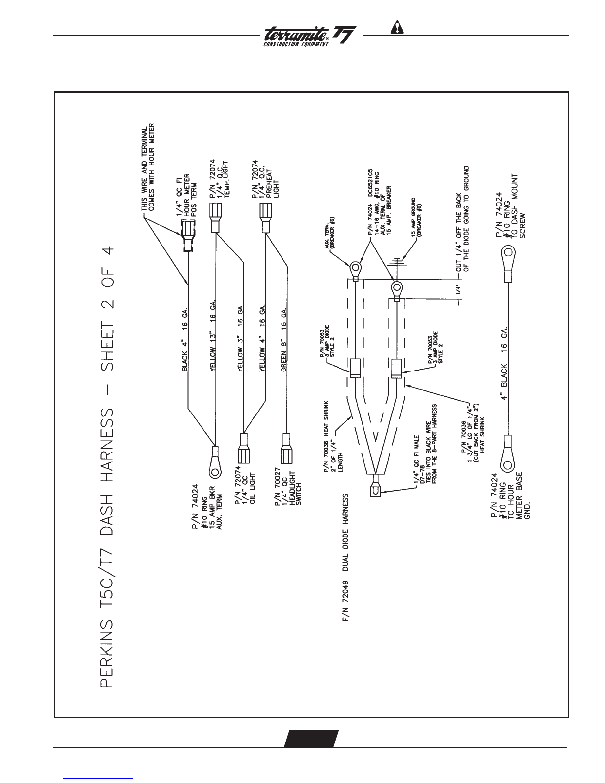
Read Operators Manual For SafetyPARTS MANUAL
Copyright © 2007 Terramite Corporation
Wiring Diagram Perkins Diesel Dash Harness (Continued)
WWW.TERRAMITE.COM
Charleston, WV/USA
4.11
USA 1.800.428.3772
Intl. 1 .304.776.4231
Page 82

Read Operators Manual For Safety PARTS MANUAL
Copyright © 2007 Terramite Corporation
Wiring Diagram Perkins Diesel Dash Harness (Continued)
WWW.TERRAMITE.COM
Charleston, WV/USA
4.12
USA 1.800.428.3772
Intl. 1 .304.776.4231
Page 83

Read Operators Manual For SafetyPARTS MANUAL
Copyright © 2007 Terramite Corporation
Wiring Diagram Perkins Diesel Dash Harness (Continued)
WWW.TERRAMITE.COM
Charleston, WV/USA
4.13
USA 1.800.428.3772
Intl. 1 .304.776.4231
Page 84

Read Operators Manual For Safety PARTS MANUAL
Copyright © 2007 Terramite Corporation
Wiring Diagram Kubota
WWW.TERRAMITE.COM
Charleston, WV/USA
4.14
USA 1.800.428.3772
Intl. 1 .304.776.4231
Page 85

Wiring Diagram Kubota
Read Operators Manual For SafetyPARTS MANUAL
Copyright © 2007 Terramite Corporation
WWW.TERRAMITE.COM
Charleston, WV/USA
4.15
USA 1.800.428.3772
Intl. 1 .304.776.4231
Page 86

Read Operators Manual For Safety PARTS MANUAL
Copyright © 2007 Terramite Corporation
WWW.TERRAMITE.COM
Charleston, WV/USA
4.16
USA 1.800.428.3772
Intl. 1 .304.776.4231
Page 87

Read Operators Manual For SafetyPARTS MANUAL
Hose and Fitting Location for V10 Valve (180 Swing)
Copyright © 2007 Terramite Corporation
WWW.TERRAMITE.COM
Charleston, WV/USA
4.17
USA 1.800.428.3772
Intl. 1 .304.776.4231
Page 88

Read Operators Manual For Safety PARTS MANUAL
Copyright © 2007 Terramite Corporation
View from Operators Position for V10 Valve (180 Swing)
2
15
3
4 Seal Kit - 1 per section, 6 required
ITEM PART NUMBER DESCRIPTION QTY.
1 84046 Kit RH Mech Pivot Section, RH, V10-1294 1
2 13942 Knob, Red Wobblestick Handle, Valve, T5C/T5D/T6/T7/T9 1
3 84045 Handle, Wobblestick, LH & RH v10-1294 1
4 85107 Kit, Section Seal, V10-1294 1
5 84047 Kit LH Mech Wobblestick, Pivot Section 1
WWW.TERRAMITE.COM
Charleston, WV/USA
4.18
USA 1.800.428.3772
Intl. 1 .304.776.4231
Page 89

Valve Section Service Kits V-10
Read Operators Manual For SafetyPARTS MANUAL
Copyright © 2007 Terramite Corporation
ITEM PART NUMBER DESCRIPTION QTY.
1 85111 Valve Section 1, Work Components V10-1294 1
ITEM PART NUMBER DESCRIPTION QTY.
1 85112 Valve Section 2, Work Components V10-1294 1
WWW.TERRAMITE.COM
Charleston, WV/USA
4.19
USA 1.800.428.3772
Intl. 1 .304.776.4231
Page 90

Read Operators Manual For Safety PARTS MANUAL
Copyright © 2007 Terramite Corporation
Valve Section Service Kits V-10
ITEM PART NUMBER DESCRIPTION QTY.
1 85113 Valve Section 3&4, Work Components, V10 - 1294 1
2
ITEM PART NUMBER DESCRIPTION QTY.
1 85114 Valve Section 5, Work Components, V10 - 1294 1
2 85116 Kit, Anti - Cavitation Check Cartridge, V10 - 1294 1
WWW.TERRAMITE.COM
Charleston, WV/USA
4.20
USA 1.800.428.3772
Intl. 1 .304.776.4231
Page 91
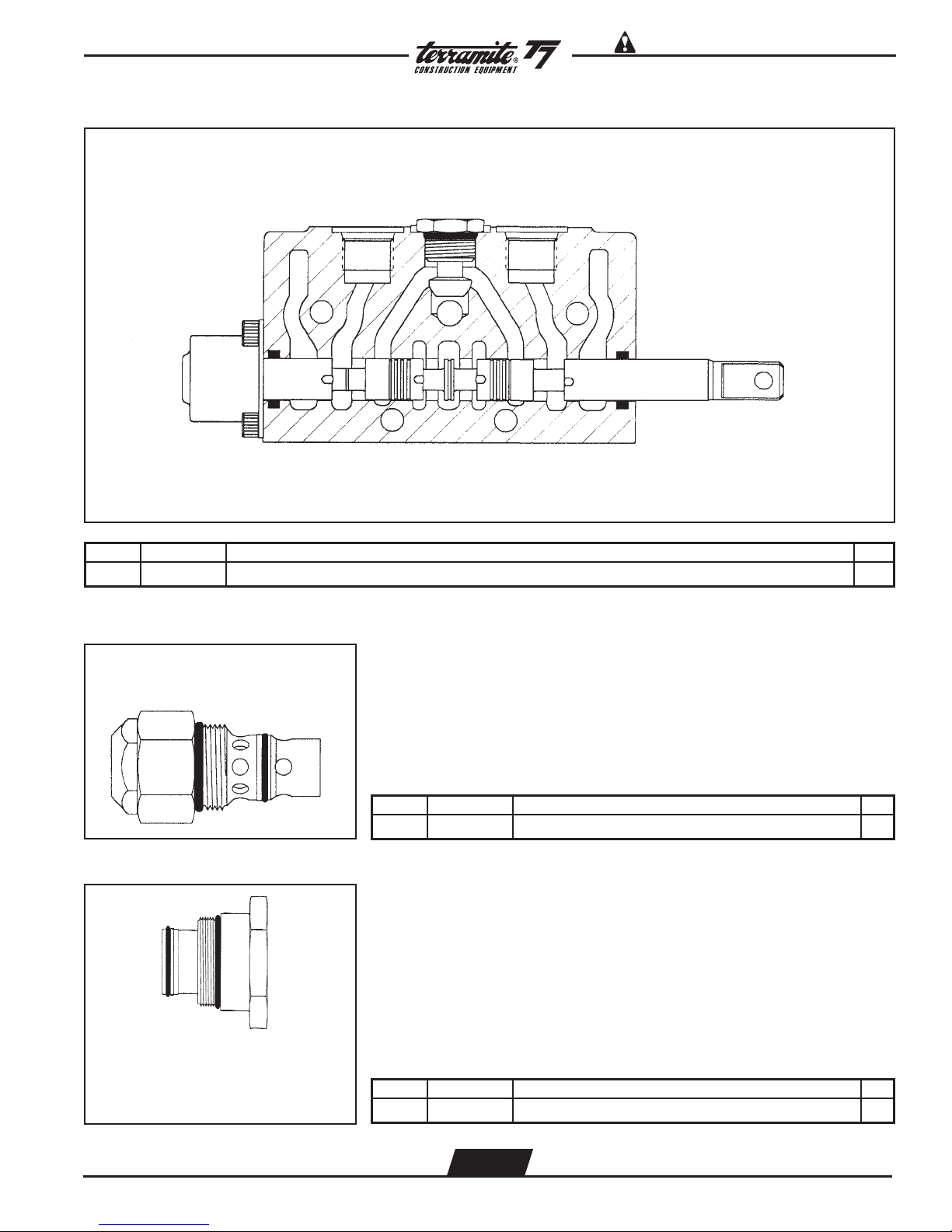
Valve Section Service Kits V-10
Read Operators Manual For SafetyPARTS MANUAL
Copyright © 2007 Terramite Corporation
ITEM PART NUMBER DESCRIPTION QTY.
1 85115 Valve Section 6, Work Components, V10 - 1294 1
ITEM PART NUMBER DESCRIPTION QTY.
1 85106
Kit, Plug Seal, Relief Cartridge, V10 - 1294
1
WWW.TERRAMITE.COM
Charleston, WV/USA
ITEM PART NUMBER DESCRIPTION QTY.
1 85123
4.21
Kit, Plug Seal, Power Beyond, V10 - 1294
1
USA 1.800.428.3772
Intl. 1 .304.776.4231
Page 92

Read Operators Manual For Safety PARTS MANUAL
Copyright © 2007 Terramite Corporation
Valve Section Service Kits V-10
ITEM PART NUMBER DESCRIPTION QTY.
1 85120 Kit, Left, Mechanical Wobblestick Pivot Section, V10-1294 1
2 85121 Kit, Right, Mechanical Wobblestick Pivot Section, V10-1294 1
WWW.TERRAMITE.COM
Charleston, WV/USA
4.22
USA 1.800.428.3772
Intl. 1 .304.776.4231
Page 93

Valve Section Service Kits V-10
Read Operators Manual For SafetyPARTS MANUAL
Copyright © 2007 Terramite Corporation
1
ITEM PART NUMBER DESCRIPTION QTY.
2 3
4
1
1 85119 Screw, Hex Head, V10 - 1294 4
2 85118 Pin, Cotter, V10 - 1294 1
3 85117 Pin, Clevis, V10 - 1294 1
4 85120 Handle, Outrigger/Offset, V10 - 1294 1
WWW.TERRAMITE.COM
Charleston, WV/USA
4.23
USA 1.800.428.3772
Intl. 1 .304.776.4231
Page 94
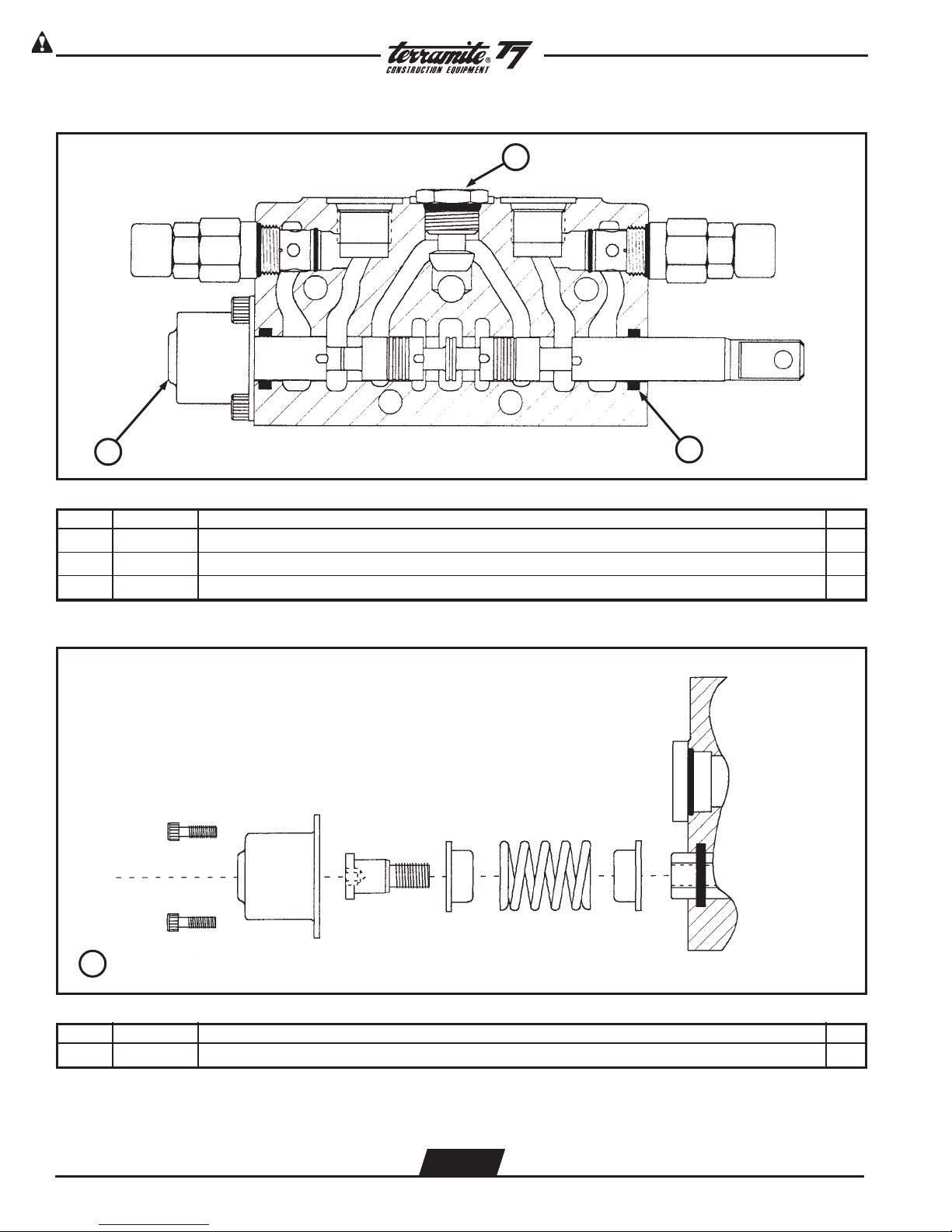
Read Operators Manual For Safety PARTS MANUAL
Copyright © 2007 Terramite Corporation
Valve Section Service Kits - V10
2
1
ITEM PART NUMBER DESCRIPTION QTY.
3
1 85108 Kit, Spool Positioner, V10 - 1294 (See Diagram Below) 1
2 85109 Kit, Load Check Plug, V10 - 1294 1
3 85110 Kit, Spool Lip Seal, V10 - 1294 1
1 Spool Positioner Kit
ITEM PART NUMBER DESCRIPTION QTY.
1 85108 Kit, Spool Positioner, V10 - 1294 1
WWW.TERRAMITE.COM
Charleston, WV/USA
4.24
USA 1.800.428.3772
Intl. 1 .304.776.4231
Page 95

Hydrastatic Transmission
CESSNA
B
Read Operators Manual For SafetyPARTS MANUAL
Copyright © 2007 Terramite Corporation
EATON
67
EATON
EATON
33A
Serial Code and Assembly Number
Location
Gas 64055 Right Hand Rotation
Diesel 64011 Left Hand Rotation
PLEASE PROVIDE SERIAL NUMBER OF MACHINE WHEN ORDERING ANY COMPONENT PARTS.
*
WWW.TERRAMITE.COM
Charleston, WV/USA
4.25
USA 1.800.428.3772
Intl. 1 .304.776.4231
Page 96

Read Operators Manual For Safety PARTS MANUAL
Copyright © 2007 Terramite Corporation
ITEM PART NUMBER HYDRASTATIC TRANSMISSION DESCRIPTION QTY.
1 60401 Retaining Ring 1
2 60402 Shaft Seal 1
3 60403 Washer 1
4 60404 Retaining Ring 2
5 60405 Bearing Race 2
6 60406 Bearing, Thrust 1
7 60471 Key 1
8 60407 Drive Shaft 1
9 60409 Housing Assembly 1
10 60410 Bearing 2
11 60411 Inner Race 2
12 60412 O-Ring, 3/32" x 15/16", Outer Pintle 2
13 60465 Sleeve Cover 1
13A 60415 Trunnion Cover 1
13B 60561 Washer 1
14 60414 Retaining Ring 2
14A 60562 Seal, Pintle 1
15 60418 Seal Cover 1
17 60564 Screws, Trunnion Cover 2
18 60516 O-Ring, Outer Pintle 1
19 60517 Camplate, For Eaton Trans. 1
19 60417 Camplate, For Cessna Trans. 1
29 60422 Rotating Kit Assembly 1
31 60429 Housing, Gasket 1
33 60533 Backplate Assy., Eaton, with Power Steering 1
33A 60535 Backplate Assy., w/valve plate, Eaton 1
33B 60432 Backplate Assy., Cessna, without Power Steering 1
35 60436 Plug Assembly 2
36 60435 O-Ring 33/32" x 7/8" ID, Back Plate 1
37 60434 Spring, Transmission, Relief Valve 2
38 60467 Relief Valve Assembly 2
39 60433 Plug Assembly 1
40 60440 Retaining Ring 1
41 60441 Separator Plug 1
42 60442 O-Ring, 33/32" x 7/8" 1
43 60454 Spreader 1
44 60437 O-Ring, 1/16" x 3/8" 1
45 60443 Coupler 1
50 64050 Gerotor and Coupler 1
51 60449 O-Ring, Molded 1
60453 Adapter Assembly without Power Steering
52 60553 Adapter Assembly with Power Steering 1
64058 Adapter Assembly with Power Steering - Diesel
53 60450 Check Valve Assembly 2
54 60452 Back Up Washer 2
55 60455 O-Ring,1/16" x 7/16" 2
56 60456 Steel Ball 2
57 60457 Pin 2
58 60461 Poppet Filter Relief 1
59 60463 Spring 1
60 60560 Spring Retainer 1
61 60469 Plug Assembly 1
62 60466 O-Ring, 33/32" x 41/64"1
64 60464 O-Ring, 1/16" x 31/4" 1
65 60465 Cover Plate 1
66 60459 Cap Screw 2
67 60534 Plate, Valve 1
*S 64100 Seal Repair Kit, Cessna 1
*S 64101 Seal Repair Kit Eaton 1
*S 60043 Rotating Rebuild Kit, Cessna 1
*S 60564 Screws, Trunnion Cover 2
68 60464 O-Ring in Back 1
WWW.TERRAMITE.COM
Charleston, WV/USA
4.26
USA 1.800.428.3772
Intl. 1 .304.776.4231
Page 97

Sunstrand Transmission
Read Operators Manual For SafetyPARTS MANUAL
Copyright © 2007 Terramite Corporation
PLEASE PROVIDE SERIAL NUMBER OF MACHINE WHEN ORDERING ANY COMPONENT PARTS.
*
WWW.TERRAMITE.COM
Charleston, WV/USA
4.27
USA 1.800.428.3772
Intl. 1 .304.776.4231
Page 98
Read Operators Manual For Safety PARTS MANUAL
Copyright © 2007 Terramite Corporation
ITEM PART NUMBER PREVIOUS PART NUMBER SUNSTRAND TRANSMISSION DESCRIPTION QTY.
B01 4250152 Housing 1
B02 500748 9008000-0132 Lip Seal 1
B03 3103218 Thrust Plate 1
B22 4250062 Cylinder block kit 1
B24 4250095 Cylinder block 1
B25 9009625-0106 Washer 2
B26 3103199 Spring 1
B28 9006250-0131 Retaining Ring 1
B32 4250127 Piston Assembly 9
B36 3103197 Slipper retainer 1
B37 425003 End cap gasket 1
B38 5000046 Needle bearing 1
B40 001289 9004800-3708 Pin 2
B43 001511 9005100-4400 Plug 3
B43A 001123 9004201-2500 O-ring 3
B45 001537 9005100-8700 Plug 2
B45A 001149 9004201-6200 O-ring 2
B50 9007200-4448 Screw 4
B52 002337 9009611-4778 Washer 3
B53 006999 9800999 Lifting Bracket 1
E04 374447 9001310-0008 Ball bearing 1
E05 5000660 Retaining ring 1
E08 9006200-0256 Retaining ring 1
E11 4250176 Seal carrier assembly 1
E11A 505536 9004100-0350 O-ring 1
N07 9004300-1460 O-ring 2
N08 4250027 Trunnion cover 1
N10 001909 9007200-3112 Screw 8
N10 516517 9007276-0135 Screw 8
S14 4800482 A pad seal 1
S15 4460586 Cover Plate 1
S16 9007200-3716 Screw 1
Swashplate
C01 4250102 Swashplate 1
C01 4510126 Swashplate kit (SB-1996-010) 1
C02 4800470 Tapered roller bearing 2
C02 508996 9001415-0006 Tapered roller bearing (SB-1996-010) 2
N05 4510026 Trunnion shim kit (SB-1996-010) 2
N06 4250043 Spacer (SB-1996-010) 2
Input Shaft
E01 4250001 Shaft, 13 tooth spline 1
E01 4250161 Shaft, 20 tooth spline 1
E01 4250013 Shaft, straight key 1
E02 509647 9003261-2524 Key 1
WWW.TERRAMITE.COM
Charleston, WV/USA
4.28
USA 1.800.428.3772
Intl. 1 .304.776.4231
Page 99

Read Operators Manual For SafetyPARTS MANUAL
Gear Pump Part Number 66000 Gas / 66001 Diesel
1
Copyright © 2007 Terramite Corporation
2 Complete Seal Kit
ITEM PART NUMBER DESCRIPTION QTY.
1 64049 Key, Coupler, Cessna 1
2 66030 Kit, Seal, Double Gear Pump 1
WWW.TERRAMITE.COM
Charleston, WV/USA
4.29
USA 1.800.428.3772
Intl. 1 .304.776.4231
Page 100
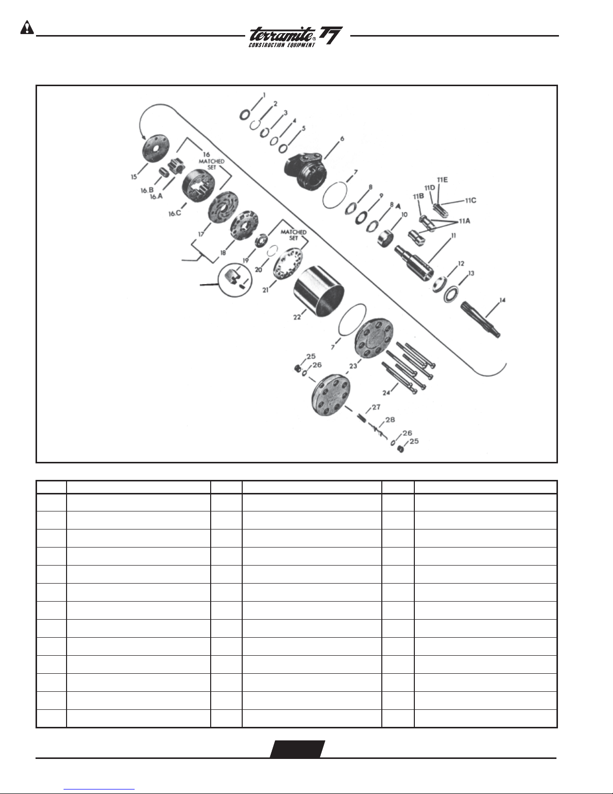
Read Operators Manual For Safety PARTS MANUAL
Copyright © 2007 Terramite Corporation
MAB/MAE Torquemotor Exploded Assembly View
ITEM DESCRIPTION ITEM DESCRIPTION ITEM DESCRIPTION
1 Seal 11B Nut 17 Manifold Plate
2 Retaining Ring 11C Washer 18 Manifold
3 Back-Up Washer 11D Bolt 19 Commutator
4 Washer 11E Lock Washer 20 Seal Ring
5 Seal 12 Bearing 21 Commutator Ring
6 Housing 13 Thrust Bearing 22 Sleeve
7 Seal Ring (2) 14 Drive Link 23 End Cover Assembly
8 Thrust Washer 15 Wear Plate 24 Special Bolt (7)
8A Thrust Washer 16 Rotor Set 25 Plug
9 Thrust Bearing 16A Rotor 26 O-Ring
10 Bearing 16B Vane (7) 27 Sping
11 Coupling Shaft 16C Stator 28 Valve (Shuttle)
11A Key
WWW.TERRAMITE.COM
Charleston, WV/USA
4.30
USA 1.800.428.3772
Intl. 1 .304.776.4231
 Loading...