

Page 1

Page 2

Page 3
Safety Tips
Safety is a prime consideration in the design of this
machine. Guards, shields and other safety features are
built in wherever possible. However, accident reports
show carelessness causes the majority of accidents. You
can avoid most accidents by observing the safety rules on
these pages. Study these rules carefully and enforce them
on the job:
Never allow minors to operate or be in the
vicinity of the machine while working.
Do not allow the T5C to be operated by anyone
who is intoxicated or on medication that would affect
their judgement or ability to operate the machine.
The machine is designed to be operated by
adults who are of average size and weight. Persons
who are extremely heavy, big or tall, or those who
are exceedingly short, light or weak can not run the
machine.
Before Operating the Terramite T5C
Read the Operator's Handbook. Never
allow anyone to operate the backhoe without
reading the Operator's Manual and Safety
Instructions. This should be followed by supervised
training.
Check Your Equipment. Always make a
complete inspection of the machine before
operating it that day. Check the hydraulic system
and the engine oil level. Then check the machine
for broken, missing or defective parts. Check the
tires for cuts, bulges, irregularities and abnormal
wear and proper inflation. Check the neutral
position of the foot pedal. A malfunctioning
machine invites accidents.
"Do Not Operate" Tag. When you service
the machine, put a "DO NOT OPERATE" Tag on
the instrument panel. This tag (Terramite Part
Number 1-400.82) is included with each machine.
Keep Your Machine Clean. Slippery
surfaces are hazardous. Remove oil, grease or mud
from the operating area of the tractor. Failure to
keep these areas clean could cause a serious
accident.
Wear What is Needed for Protection.
Protect yourself by wearing all the protective
clothing and personal safety devices issued to you
or required by job conditions. You may need a hard
hat, safety shoes, safety glasses, heavy gloves,
hearing protection, reflective clothing, wet weather
gear and a respirator. Never take chances by wearing
loose clothing, watches or rings.
Look For Hazards. Walk around a new work
area and check for any hidden hazards, such as holes
and abutments.
Read and Heed Safety Decals. Make sure
the safety and information decals can be easily read.
To clean decals, use soap and water only. Gasoline
or solvents will destroy the decals. If these decals
are missing or illegible, call our Parts/Service
Department for replacements.
Roll-Over Protective Structure. All
Terramite T5C tractor loader backhoes are equipped
with a Roll-Over Protective Structure. This is
designed to protect the operator in the event of a
roll-over. If this machine has been rolled over, the
R.O.P.S. must be replaced. It is designed to be used
only once.
Driving Pivot Pins. When driving pivot pins
in or out, use care to guard against injury from
particles that may chip off the pin or object used in
striking the pin. These pins can fly out at high speed
if they are not tapped lightly just before they come
out. Make sure there isn't anyone or anything in
the way, in case the pin flies out. Safety glasses
should be worn.
See Operator's Manual For More Safety Information
1.1
Page 4

Before Your Start
READ OPERATOR'S HANDBOOK
Carefully read all WARNING! and DANGER! messages in handbook
and be sure you understand their meanings.
IMPORTANT! If this machine is used by the owner, an employee, or is
loaned or rented, make sure that the following instructions are complied
with:
1. The operator has read the Operation and the Safety Rules
sections of the Operator's Handbook.
2. He has been instructed on the safe and correct use of the
machine.
3. He has practiced operating the machine and the use of all
controls in a safe, clear area before he operates the machine on a
job site.
4. He has read all safety decals on the machine.
5. He has been informed to clear the area of other persons and
hidden hazards before starting the machine.
1.2
Page 5

Table of Contents
Safety - Important ................................................ 1.1
Before Operating the Terramite T5C................... 1.2
Section Two: HYDRAULICS
Oil Change and Type Specifications .................... 2.1
Front with Loader Arm Assembly Raised ............. 2.2
Loader Valve Hoses and Fittings
Under Fuel Tank Hood Assembly ........................ 2.3
Transmission Assembly ......................................... 2.4
Rear Valve ...................................................... 2.5-2.7
Gear Pump Part #66045 ...................................... 2.8
Rod Assembly ....................................................... 2.9
Hydrastatic Transmission .................................... 2.10
Hydraulic Main Power Circuits(Gas Model) ...... 2.11
Hydraulic Main Power Circuit ........................... 2.12
Loader Circuit .................................................... 2.13
Woddlestick Hose Diagram Backhoe Circuit ..... 2.14
MAB/MAE Torquemotor Exploded................... 2.15
Power Steering Column Exploded ..................... 2.16
Schematic - Backhoe Control Valve .................. 2.17
Parts Ordering Information ................................ 2.18
V20 Seal Identification Chart
Loader Valve ...................................................... 2.19
4-Way, 3-Position Valve Section ......................... 2.20
Loader Check Plug / High Pressure Releif .......... 2.21
Section Four: ELECTRICAL WIRING
Diagram Kohler Magnum 20 HP ......................... 4.1
Diagram Kohler Command 20/25 HP .................. 4.2
Harness/A-Kohler Command ............................... 4.3
Diagram Honda 20 HP ........................................ 4.4
(Pre - 1997 Model) .......................................... 4.5
Harness/A-Relay Harness ..................................... 4.6
Harness/Honda Engine ........................................ 4.7
Harness/Honda Voltage Regulator Harness/
A-Relay Harness ............................................... 4.8
Harness - Honda Dash ......................................... 4.9
Section Five: OPTIONS
Tires ..................................................................... 5.1
Work Lights and Canopy/Mounted Lights
Strobe Light ..................................................... 5.2
Clam Shell 4 in 1 Bucket ..................................... 5.3
Under Dash for Clam Shell 4 in 1 Bucket ........... 5.4
Drive Position
Dash for Clam Shell Buck ................................ 5.5
Street Pads/Flip Over Pads/Tooth Caps ................ 5.6
Quick Attach Backhoe Buckets (After 5-1-98) ... 5.7
Auger (Bradco./McMillen)................................... 5.8
Auger Connections .............................................. 5.9
Back-up Alarm and Connections....................... 5.10
Section Three: COMPONENTS
Seat Assembly ...................................................... 3.1
Exploded View of Front End Loader .................... 3.2
Exploded View of Dash ........................................ 3.4
Under the Hood - Kohler Command Engine ....... 3.6
Drive Shaft Coupler ............................................. 3.7
View from Behind Center Steer ........................... 3.8
View from Behind Dash ..................................... 3.10
Front Wheel Hubs / Hub Assembly and Spindle 3.12
Front / Rear Tires and Rims ................................ 3.13
Parking Brake Assembly ..................................... 3.14
Retro Fit Parking Brake Spring Assembly ........... 3.16
Front of Rear Axle - Parking Brake Assembly .... 3.16
Exploded View of Dipstick ................................. 3.17
Backhoe Assembly ............................................. 3.18
Rear Axle Assembly ........................................... 3.20
Pin Schematic .................................................... 3.22
General Tightening Torque for Bolts, Nuts
and Taperlock Studs ........................................... 3.23
Decal Location Right Side ................................. 3.24
Decal Location - Dash ....................................... 3.25
Decal Location - Rear ........................................ 3.26
Couplings ........................................................... 3.27
Section Six: TRANSLATIONS
Translations ................................................ 6.1 to 6.6
Section SEVEN: INDEX & SAMPLE WARRANTY
Index .......................................................... 7.1 to 7.5
Sample Warranty .................................................. 7.6
RECORDS
Serial Number _________________________
Model# ______________________________
Engine Type: __________________________
Engine Serial Number: __________________
Accessories: ___________________________
____________________________________
____________________________________
____________________________________
1.3
Page 6

1.4
Page 7
Read Operators Manual For Safety
PARTS MANUAL
Hydraulics
Oil Change and Type Specifications
When your machine is new, the hydraulic system oil and filter must be changed within the first 50
hours of use and every 250 thereafter. Refill the hydraulic reservoir with engine oil type API SF.CD
15W40 when outside temperature is above 40 degrees F. Use engine oil type API SF.CD 10 weight
when outside temperature is below 40 degrees F. Replace filter with Terramite / 21002 filter. It is
important to follow these instructions to alleviate any cold weather engine starting problems and any
pressure or heat related component failures.
DO NOT USE REGULAR HYDRAULIC OIL!
MAJOR DAMAGE WILL RESULT!
This is the position machine must be in to check proper level in
hydraulic tank.
Required Pre-Fuel Filter Changes for Gasoline and Diesel Machines
ALL Terramite Backhoes and Street Sweepers require their pre-fuel filters to be changed at the first
20 hours and again at 40 hours. These pre-fuel filters should be changed every 20 to 50 hours
thereafter using a 10 micron filter.
The following Pre-fuel filters are designed for gasoline and diesel engines.
Terramite 15506
NOTE:NOTE:
NOTE: Filling tank with loader or backhoe in any other position will result in overfilling and spillage of fluid
NOTE:NOTE:
through the breather cap. Replace cap if oil should ever spill out of breather cap since it will clog off
the air supply that the systems needs to operate properly.
1.800.428.3772
Intl. 1 .304.776.4231
WWW.TERRAMITE.COM/SAFETY
Copyright © 2006 Terramite Corporation
Charleston, WV/USA
2.1
Page 8
Read Operators Manual For Safety
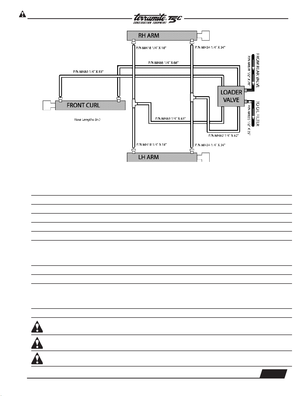
Hydraulics
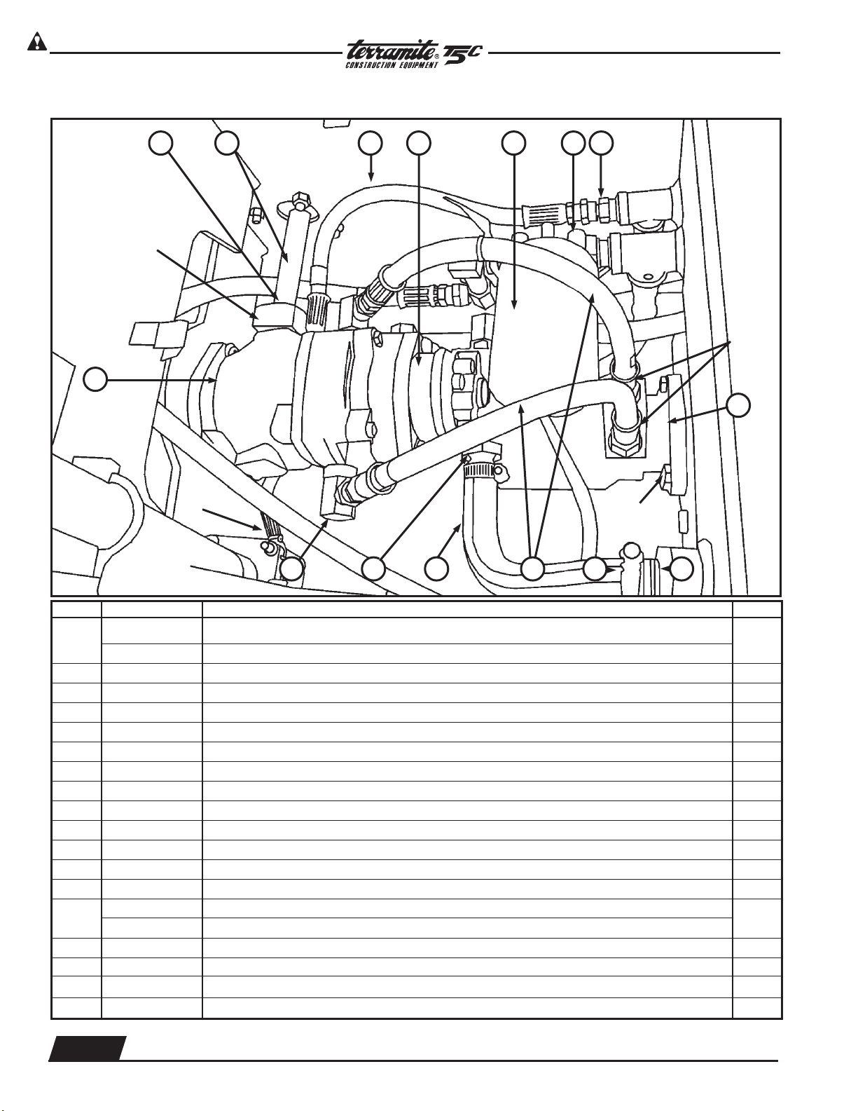
View from Front with Loader Arm Assembly Raised
PARTS MANUAL
1
4
ITEM PART NUMBER DESCRIPTION QTY.
7
2
6
3
8
5
1
4
1 88418 Hose, 1/4" x 18" (front hose set) 2
2 22244 Fitting, 1/4" Tee (front hose set) 2
3 20174 Fitting, 1/4" (front hose set) 26
4 88434 Hose, 1/4" x 34" (front hose set) 2
5 22174 Fitting, 1/4" x 90° (front hose set) 5
6 88462 Hose, 1/4" x 62" (front hose set) 1
7 88463 Hose, 1/4" x 63" (front hose set) 1
8 12033 Distributor Block 1
2.2
WWW.TERRAMITE.COM/SAFETY
Charleston, WV/USA
Copyright © 2006 Terramite Corporation
1.800.428.3772
Intl. 1 .304.776.4231
Page 9
Read Operators Manual For Safety
PARTS MANUAL
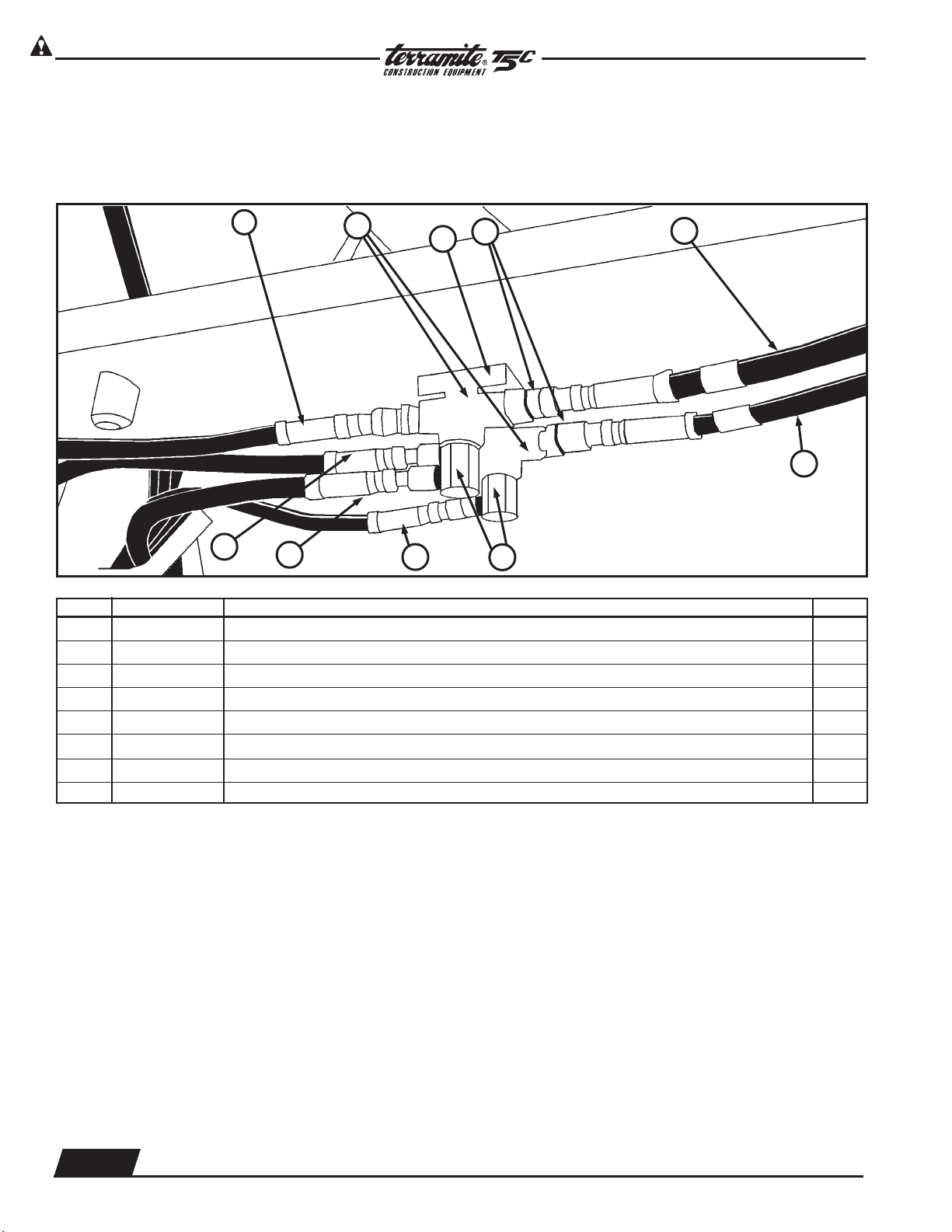
View of Loader Valve Hoses and Fittings from Right Side of Engine
Compartment Under Fuel Tank Hood Assembly
1 2 3 4 5 6
Hydraulics
78
ITEM PART NUMBER DESCRIPTION QTY.
1 85015 Valve, Loader(No Fittings) 1
1 84070 Valve, Loader(With Fittings) 1
2 88483 Hose, 1/4" x 83", Loader Valve 1
3 88466 Hose, 1/4" x 66", Loader Valve 1
4 88463 Hose, 1/4" x 63", Loader Valve 1
5 88462 Hose, 1/4" x 62", Loader Valve 1
6 88835 Hose, 1/2" x 35", Loader Valve 1
7 22278 Fitting, 1/2" x 90°, Loader Valve 1
8 22784 Fitting, 1/2" x 1/4" x 90°, Loader Valve 4
13096 Front Valve Seal Kit 1
1.800.428.3772
Intl. 1 .304.776.4231
WWW.TERRAMITE.COM/SAFETY
Copyright © 2006 Terramite Corporation
2.3
Charleston, WV/USA
Page 10
Read Operators Manual For Safety
Hydraulics
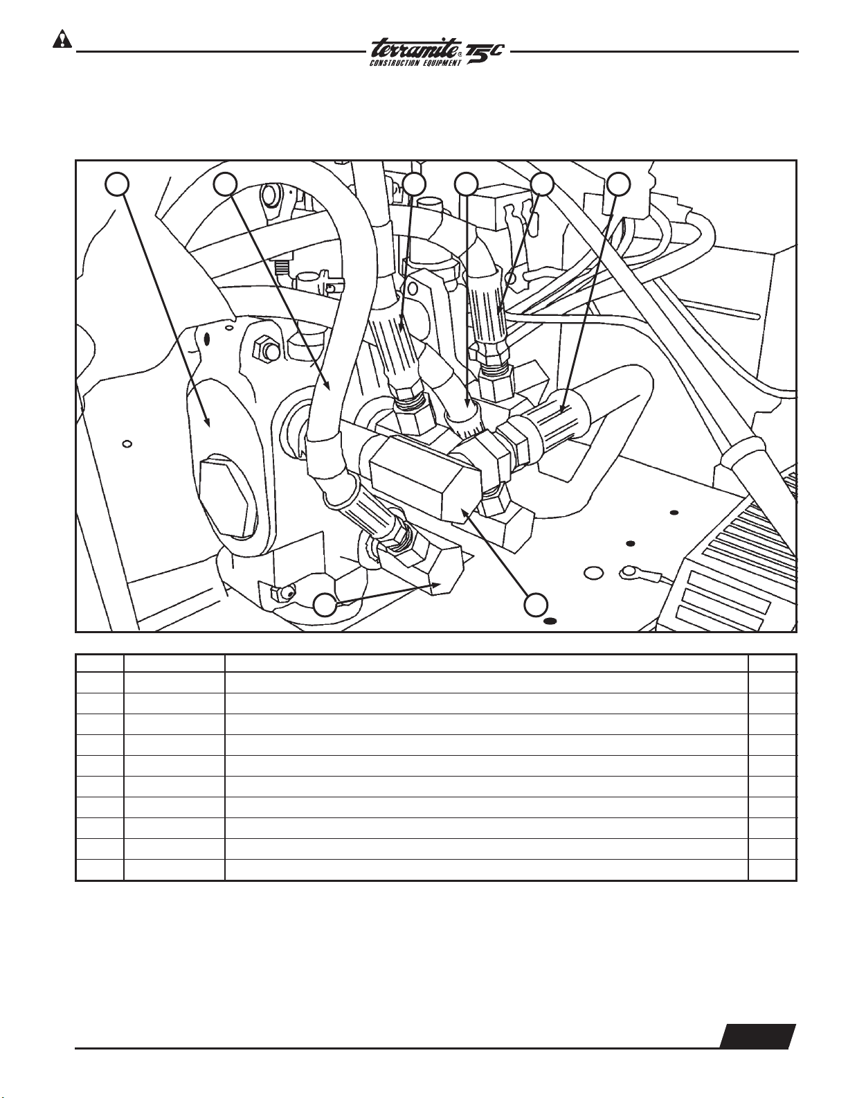
View from Top - Transmission Assembly
PARTS MANUAL
Block #13054
Roll Pin #17005
1
2
PN#80037
3 4 5 6 7 8
Fitting
#20007
10
Bolt #22034
Nut #28500
111213141516
ITEM PART NUMBER DESCRIPTION QTY.
1
64064 Hydrostatic Transmission Gas Only (Resale)
1
64012 Hydrostatic Transmission Diesel Only
2 11620 Pedal Shaft 1
3 61623 Pedal Shaft Bushing 1
4 88615 Hose, 3/8” x 15”, Transmission 1
5 66045 Gear Pump 1
6 21002 Filter, Hydraulic 1
7 22003 Filter Base 1
8 21786 Fitting, 1/2” x 3/8”, Trans. 1
9 15900 Tank, Hydraulic, T5 1
10 64003 Torquemotor 1
11 22201 Filter, Strainer (Inside Tank) 1
12 22020 Clamp, Hose 2
13 88820 Hose, 1/2” x 20”, Trans. 2
14
81012 Hose, 3/4" x 12", Trans. prior to 11-92
81010 Hose, 3/4" x 12", Trans. after 11-92
1
15 81612 Fitting, 11/16” x 3/4”, Trans. 1
16 27128 Fitting, #12 x 1/2" x 90°, Trans. 2
25286 Fitting On Bottom of Transmission
22118 Fitting For Charge Plate Adapter 3/8 90%
2.4
WWW.TERRAMITE.COM/SAFETY
Charleston, WV/USA
Copyright © 2006 Terramite Corporation
1.800.428.3772
Intl. 1 .304.776.4231
Page 11
Read Operators Manual For Safety
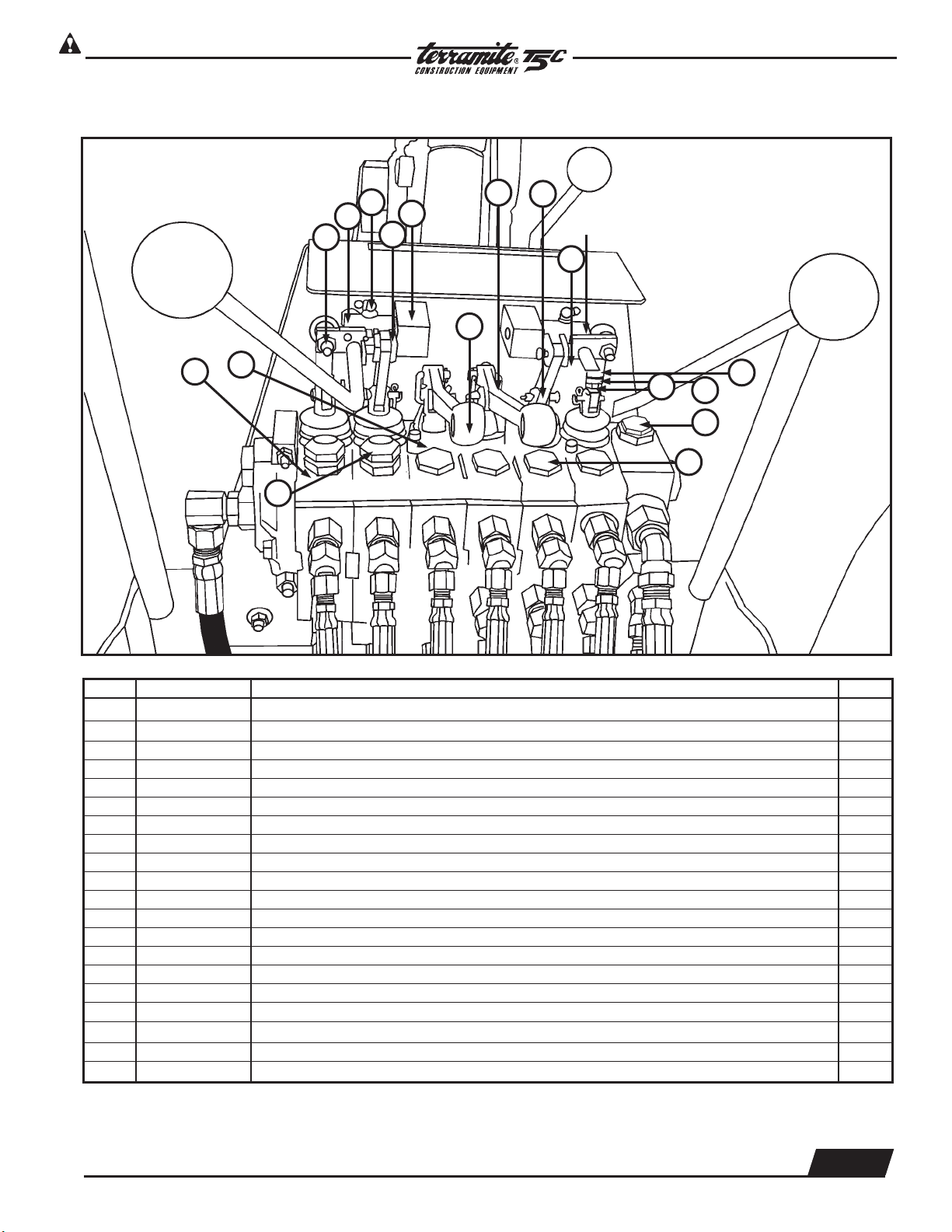
View from Operator Position of Rear Valve
1
PARTS MANUAL
Hydraulics
6
3
2
18
8
12
5
Bolt 10
14
17
7
3
4
7
13
15
16
ITEM PART NUMBER DESCRIPTION QTY.
1 25500 Nut, 5/16" NF Jam 2
2 13444 Wobblestick Pivot Block, Universal 1
3 16410 Eye Bolt 2
4 13965 Linkage 3
5 13443 Connecting Link 2
6 13411 Valve Link 3
7 13410 Aluminum Valve Handle Bracket 2
8 13418 Pin, Valve Hose Link Pivot 8
9 21429 90o Grease Fitting 1
10 23008 Nut on back of Wobblestick 1
11 13443 Lock Nut 1
12 13431 Outrigger Handles 2
13 13429 Main Relief Rear Valve 1
14 13423 Valve Boot Spool Protector 4
15 13401 Load Check Plug Assembly 9
16 13456 Port Relief 2600# 1
17 13454 Port Relief 2000# 2
18 13444 Uni Blocks
85041 Orings 6
13499 Pressure Shims
1.800.428.3772
Intl. 1 .304.776.4231
WWW.TERRAMITE.COM/SAFETY
Copyright © 2006 Terramite Corporation
2.5
Charleston, WV/USA
Page 12
Read Operators Manual For Safety
Hydraulics
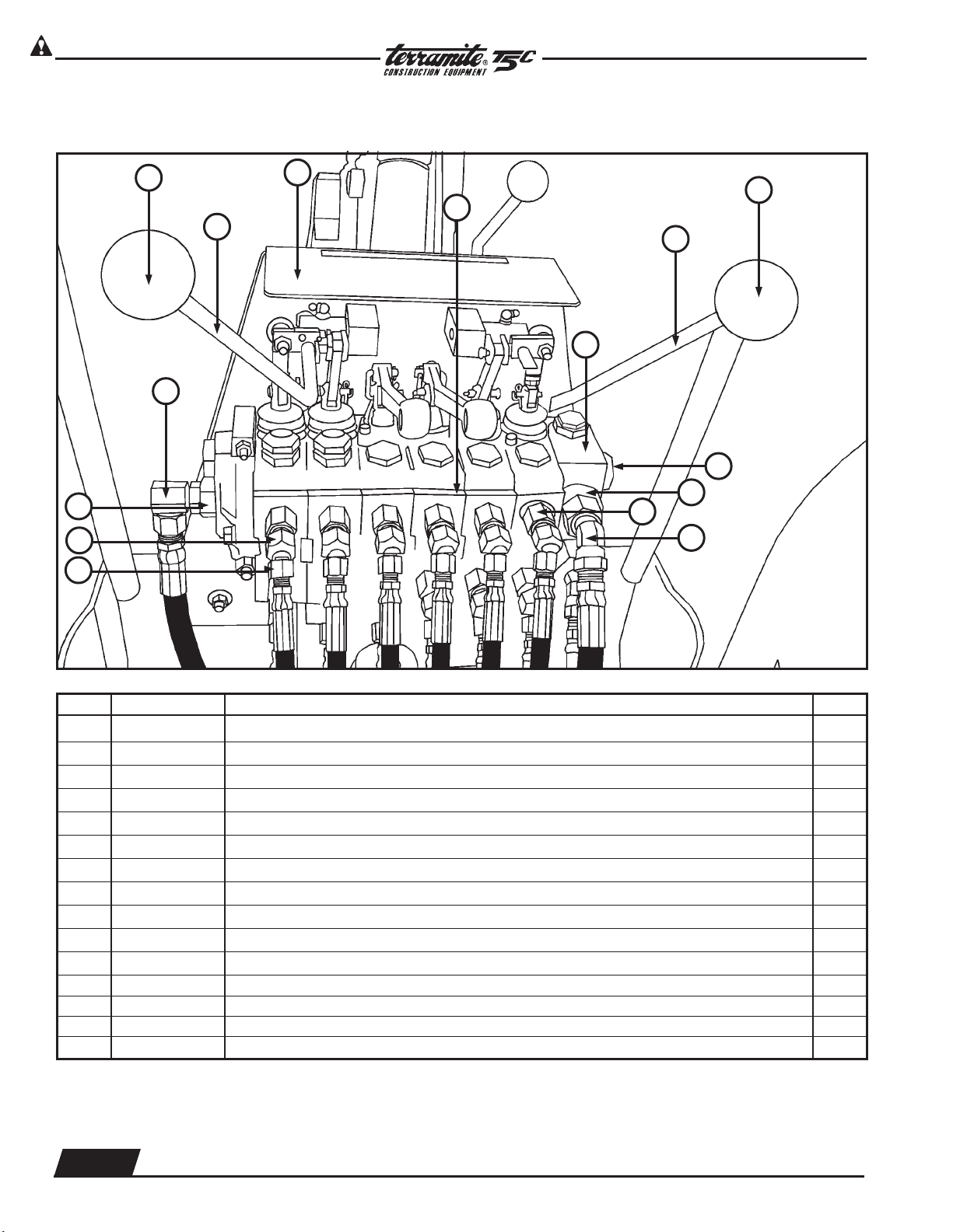
View from Operator Position of Rear Valve
PARTS MANUAL
12
10
9
1
2
11
3
1
18
4
5
End Cap
13
6
8
7
ITEM PART NUMBER DESCRIPTION QTY.
1 13942 Knob 2
2 13073 Handle, Wobblestick, Left Rear 1
3 14050 Decal, Wobblestick & Operator Hazard 1
4 13123 Handle, Wobblestick, Right Rear 1
5 13400 Rear Valve Assembly 1
6 20065 Fitting, #12 x 8" adaptor 2
7 21788 Fitting, #8 x 1/2" x 45° 2
8 25286 Fitting, #8 x 6" adaptor 12
9 21764 Fitting, 3/4" x 1/4" x 45° 9
10 21765 Fitting, Restrictor 3
11 25108 Fitting, #10 x 1/2" x 90° 1
13444 Block
12 84029 Power Beyond - Sleeve Kit
13 85156 End Cap
14 26002 Restrictor Sets Screws
2.6
WWW.TERRAMITE.COM/SAFETY
Charleston, WV/USA
Copyright © 2006 Terramite Corporation
1.800.428.3772
Intl. 1 .304.776.4231
Page 13
Read Operators Manual For Safety
PARTS MANUAL
Hydraulics
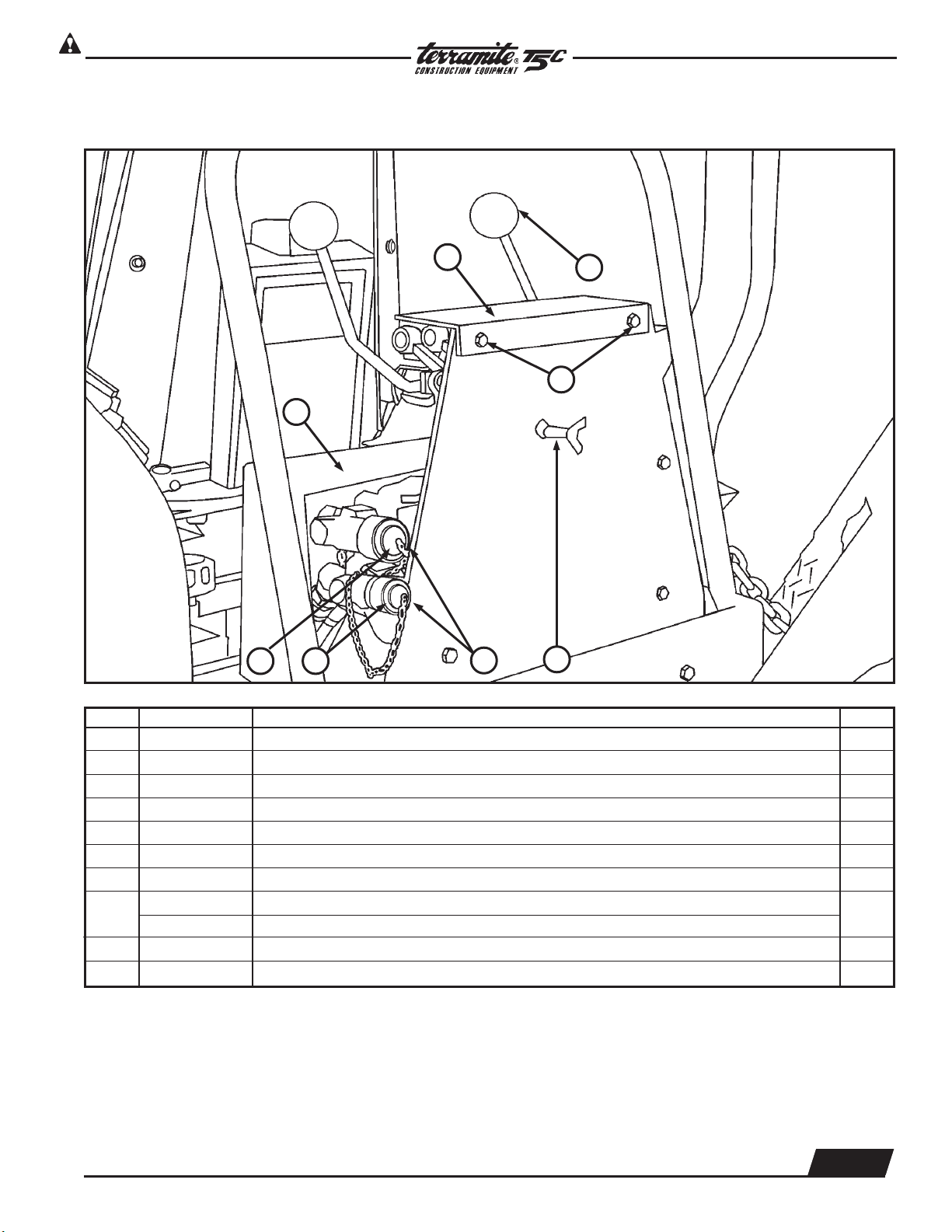
View from Right Rear
5
9
1
2
3
6
8
4
ITEM PART NUMBER DESCRIPTION QTY.
1 25054 Q.A. Plug 1
2 27010 Threaded Q.A. Plug 1
3 28890 Auxiliary P.T.O. Kit 1
NOT
SHOWN
21188 Fittings, 1/2” x 90° 2
4 26485 P.T.O. Depress Lever 1
5 14052 Decal Plate For Handle Operations 1
6 13942 Wobblestick Knob 2
14005 Maintenance Decal (Gas Only) Located Under Dash Not Shown
7
14510 Maintenance Decal (Diesel Only) Located Under Dash Not Shown
8 Bolts 2
9 15017 Hose Cover
1.800.428.3772
Intl. 1 .304.776.4231
Copyright © 2006 Terramite Corporation
WWW.TERRAMITE.COM/SAFETY
Charleston, WV/USA
1
2.7
Page 14
Read Operators Manual For Safety
PARTS MANUAL
Hydraulics
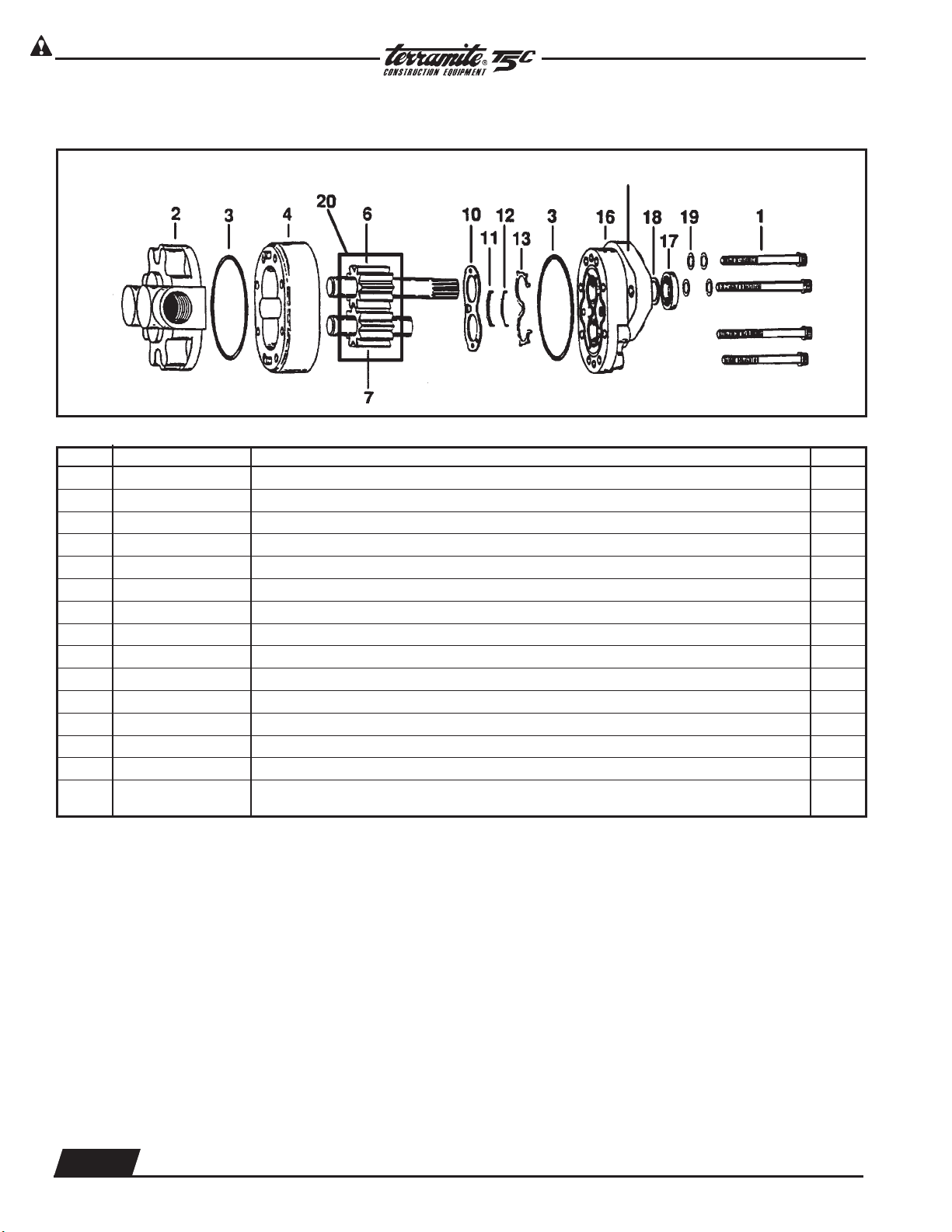
Gear Pump Part # 66045
Serial Code and Assembly Number
ITEM PART NUMBER DESCRIPTION QTY.
1 NSS* Cap Screws 8
2 64501 Backplate Assembly 1
3 60464 O-Ring 1/16" x 3" 1
4 64504 Body 1
6 64505 Drive Gear Assembly 1
7 64506 Idler Gear Assembly 1
10 NSS* Wear Plate 1
11 NSS* Bearing Seal 1
12 NSS* Molded O-Ring 1
13 NSS* Back Up Gasket 1
16 64513 Front Plate 1
17 64514 Seal, Gear Pump, Shaft 1
19 65131 Washer, Gear Pump 4
SP 65101 Seal Repair Kit 1
20 66010 2-Keys 2
NSS* Not Sold Separately
2.8
WWW.TERRAMITE.COM/SAFETY
Charleston, WV/USA
Copyright © 2006 Terramite Corporation
1.800.428.3772
Intl. 1 .304.776.4231
Page 15
Read Operators Manual For Safety
1 2 3 4
ROD BEARING BLOCK PISTON SEAL KIT
RO D PART PART PART PART
DIAMETER NUMBER NUMBER NUMBER NUMBER
PARTS MANUAL
Hydraulics
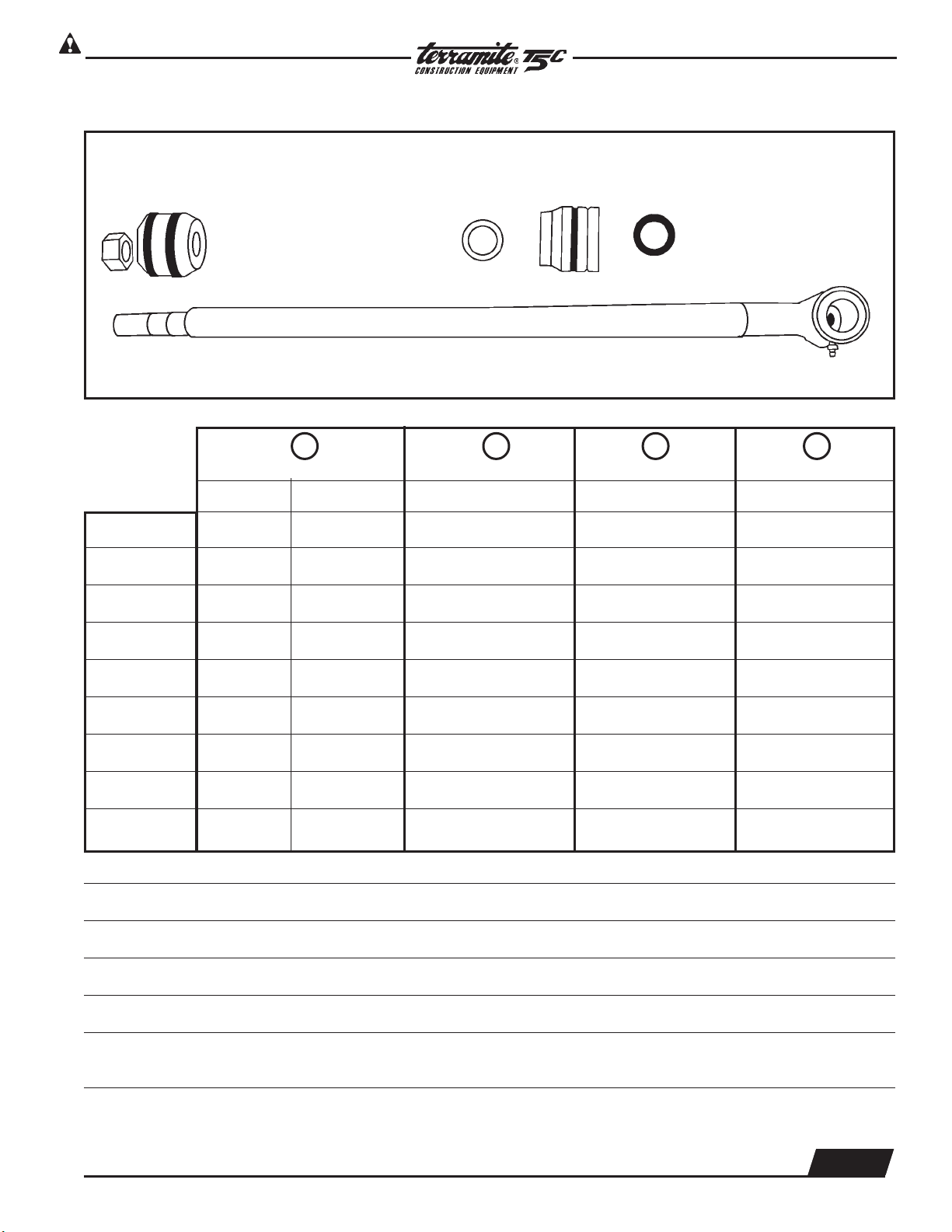
Rod Assembly
Arm 1" 22501 22103 21111 21151
Power Steering 1" 25803 22103 21111 21151
Swing 1" 25201 22103 21111 21151
Front Curl 11/8" 23101 22203 21111 21125
Rear Curl* 11/8" 20301 22203 21111 21125
Outrigger 11/8" 21601 22203 21111 21125
Boom Lift 11/4" 21201 82058 23110 21525
Boom Crowd 11/4" 21201 82058 23110 21525
2 inch 11/4" 81048 82104 21111 82051
*Standard
**On machines manufactured before 6-96 part number is 25801 (Previous Part Number 1-58.1).
NOT SHOWN: Rear Curl Rod 1
1
/4" Part Number: 81048
NOTE: All rod assemblies use the same locknut Part Number 23420 (Previous Part Number 1N12FL).
NOTE: Units dated before 4-91 use aluminum pistons in 2" ID Cylinder Barrels only.
Use Seal Kit 2-15.1 (New #82049 for 1" kit-Prior to 4/94 Aluminum)
and 2-15.1125 (New #82050 for 11/8" kit-Prior to 4/94 Aluminum).
SPECIAL TOOL 21176 Spanner wrench for cylinder repair
1.800.428.3772
Intl. 1 .304.776.4231
Copyright © 2006 Terramite Corporation
WWW.TERRAMITE.COM/SAFETY
Charleston, WV/USA
2.9
Page 16
Read Operators Manual For Safety
Hydraulics
CESSNA
B
PARTS MANUAL
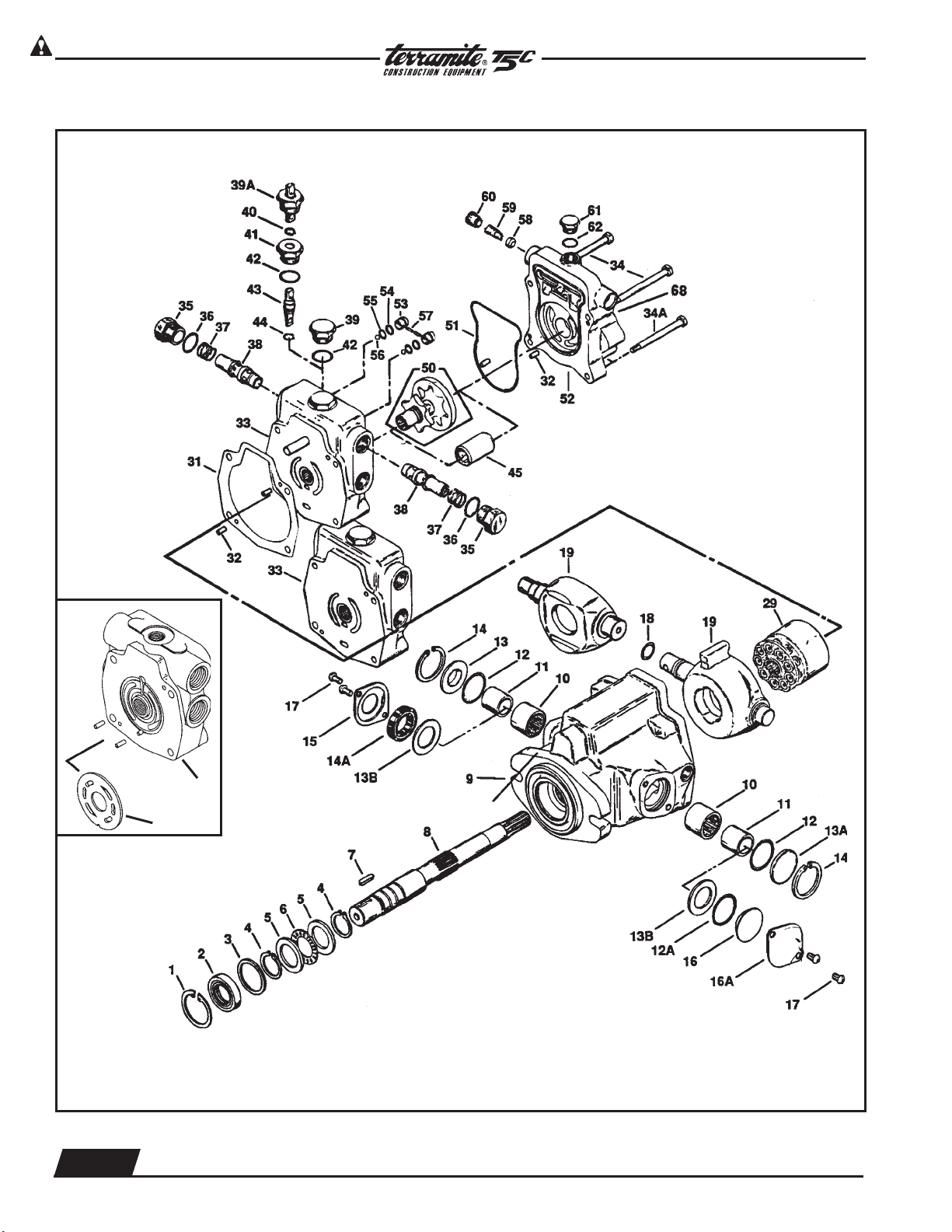
Hydrastatic Transmission
EATON
67
33A
EATON
Serial Code and Assembly Number
Location
EATON
CESSNA
PLEASE PROVIDE SERIAL NUMBER OF MACHINE WHEN ORDERING ANY COMPONENT PARTS.
*
2.10
WWW.TERRAMITE.COM/SAFETY
Charleston, WV/USA
Copyright © 2006 Terramite Corporation
1.800.428.3772
Intl. 1 .304.776.4231
Page 17

Read Operators Manual For Safety
PARTS MANUAL
Hydraulics
ITEM PART NUMBER DESCRIPTION QTY.
1 60401 Retaining Ring 1
2 60402 Shaft Seal 1
3 60403 Washer 1
4 60404 Retaining Ring 2
5 60405 Bearing Race 2
6 60406 Bearing, Thrust 1
7 60471 Key 1
8 60407 Drive Shaft 1
9 60409 Housing Assembly 1
10 60410 Bearing 2
11 60411 Inner Race 2
12 60412 O-Ring, 3/32" x 15/16", Outer Pintle 2
13 60465 Sleeve Cover 1
13A 60415 Trunnion Cover 1
13B 60561 Washer 1
14 60414 Retaining Ring 2
14A 60562 Seal, Pintle 1
15 60418 Seal Cover 1
17 60564 Screws, Trunnion Cover 2
18 60516 O-Ring, Outer Pintle 1
19 60517 Camplate, For Eaton Trans. 1
19 60417 Camplate, For Cessna Trans. 1
29 60422 Rotating Kit Assembly 1
31 60429 Housing, Gasket 1
33 60533 Backplate Assy., Eaton, with Power Steering 1
33A 60535 Backplate Assy., w/valve plate, Eaton 1
33B 60432 Backplate Assy., Cessna, without Power Steering 1
35 60436 Plug Assembly 2
36 60435 O-Ring 33/32" x 7/8" ID, Back Plate 1
37 60434 Spring, Transmission, Relief Valve 2
38 60467 Relief Valve Assembly 2
39 60433 Plug Assembly 1
40 60440 Retaining Ring 1
41 60441 Separator Plug 1
42 60442 O-Ring, 33/32" x 7/8" 1
43 60454 Spreader 1
44 60437 O-Ring, 1/16" x 3/8" 1
45 60443 Coupler 1
50 64050 Gerotor and Coupler 1
51 60449 O-Ring, Molded 1
60453 Adapter Assembly without Power Steering
52 60553 Adapter Assembly with Power Steering 1
64058 Adapter Assembly with Power Steering - Diesel
53 60450 Check Valve Assembly 2
54 60452 Back Up Washer 2
55 60455 O-Ring,1/16" x 7/16" 2
56 60456 Steel Ball 2
57 60457 Pin 2
58 60461 Poppet Filter Relief 1
59 60463 Spring 1
60 60560 Spring Retainer 1
61 60469 Plug Assembly 1
62 60466 O-Ring, 33/32" x 41/64"1
64 60464 O-Ring, 1/16" x 31/4" 1
65 60465 Cover Plate 1
66 60459 Cap Screw 2
67 60534 Plate, Valve 1
*S 64100 Seal Repair Kit, Cessna 1
*S 64101 Seal Repair Kit Eaton 1
*S 60043 Rotating Rebuild Kit, Cessna 1
*S 60564 Screws, Trunnion Cover 2
68 60464 O-Ring in Back 1
1.800.428.3772
Intl. 1 .304.776.4231
WWW.TERRAMITE.COM/SAFETY
Copyright © 2006 Terramite Corporation
2.11
Charleston, WV/USA
Page 18
Read Operators Manual For Safety
Hydraulics
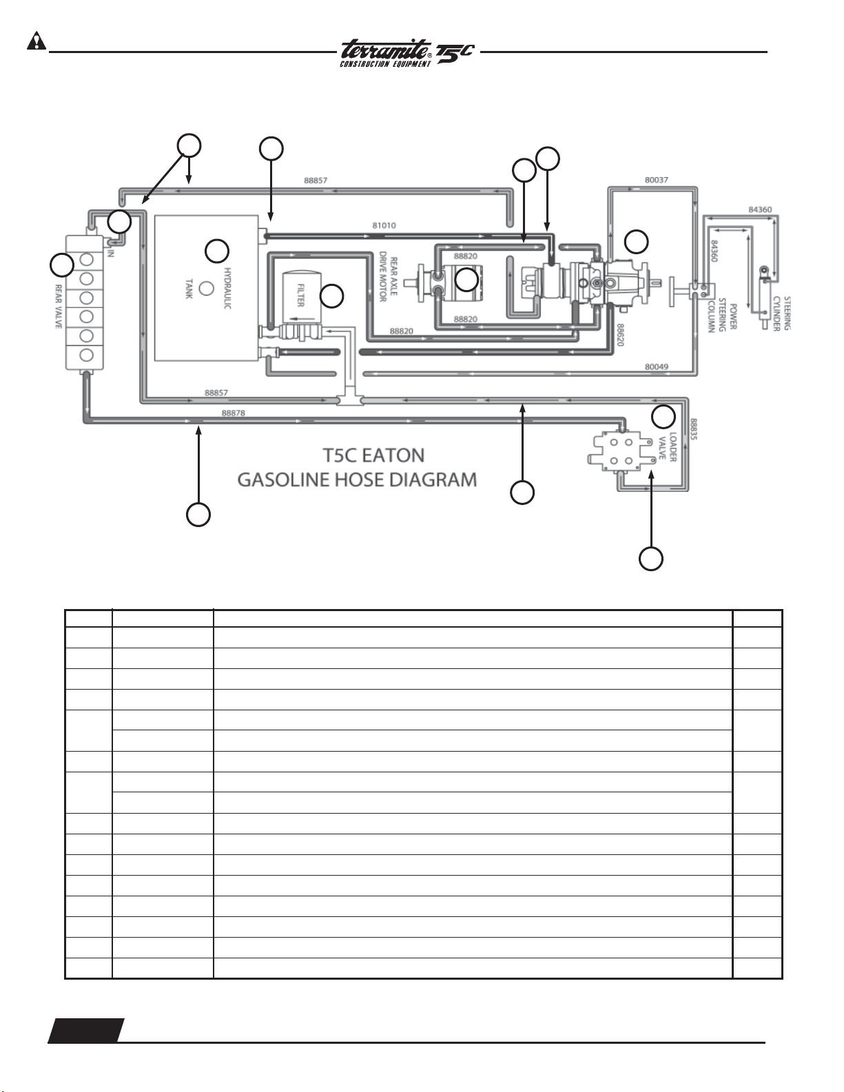
Hydraulic Main Power Circuit (shown is for gas model)
PARTS MANUAL
15
2
1
14
11
3
4
13
5
6
7
8
10
9
ITEM PART NUMBER PREVIOUS PART NUMBER DESCRIPTION QTY.
1 13429 Main Relief Rear Valve 1
2 88857 Hose 1/2" x 57" (back valve section) 2
3 22201 Filter, Strainer (Inside Tank) 1
4 64003 Drive Motor 1
5
81012 Hose, 3/4" x 12"(back valve section) Prior to 11-92
81010 Hose, 3/4" x 12"(back valve section) After 11-92
1
6 88820 Hose, 1/2" x 20"(back valve section) 3
7
66005 Transmission Gasoline Type
66006 Transmission Diesel Equipped
1
8 13900 Valve Loader 1
9 13943 Loader Circuit Relief Valve 1
10 88836 Hose, 1/2" x 36"(back valve section) 1
11 88878 Hose, 1/2" x 78"(back valve section) 1
12 88620 Hose, 3/8" x 20"(back valve section) 1
13 21002 Filter, Hydraulic 1
14 22204 Cap, Hyd. Breather Filter w/Dipstick 1
15 13400 Rear Valve Assembly 1
Continued On Next Page
2.12
WWW.TERRAMITE.COM/SAFETY
Charleston, WV/USA
Copyright © 2006 Terramite Corporation
1.800.428.3772
Intl. 1 .304.776.4231
Page 19
Read Operators Manual For Safety
Loader Circuit
PARTS MANUAL
Hydraulics
Hydraulic Main Power Circuit (Continued)
HYDRAULIC FILTER TYPES:
PARKER 921999
NAPA 1551-1259
WIX 51551
FRAM P-1653
AC PF16
BALDWIN BT-839-10
HOSE TYPES:
3
/8" 2 WIRE BRAID MP6-6 & MB6-6F
1
/2" 2 WIRE BRAID NPT
3
/4" SUMP LINE HOSE
OIL:
ABOVE 40°F - API 15W-40 SF/CC/CD
BELOW 40°F - API 10w SF/CC/CD
WARNING: USE ONLY 2 WIRE BRAID HOSES AS SPECIFIED ABOVE. SYNTHETIC OR OTHER TYPES OF
HOSES MAY FAIL CAUSING SERIOUS INJURY OR DEATH.
WARNING: DO NOT USE ORDINARY HYDRAULIC OIL OR MAJOR DAMAGE TO TRANSMISSION AND
MOTOR WILL RESULT.
NOTE: For Diesel, switch hoses marked A and B
1.800.428.3772
Intl. 1 .304.776.4231
WWW.TERRAMITE.COM/SAFETY
Copyright © 2006 Terramite Corporation
2.13
Charleston, WV/USA
Page 20
Read Operators Manual For Safety
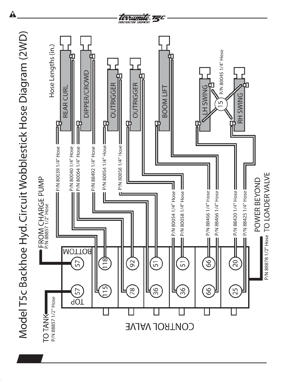
Hydraulics
T5C Wobblestick Hose Diagram Backhoe Circuit
PARTS MANUAL
2.14
WWW.TERRAMITE.COM/SAFETY
Charleston, WV/USA
Copyright © 2006 Terramite Corporation
1.800.428.3772
Intl. 1 .304.776.4231
Page 21
Read Operators Manual For Safety
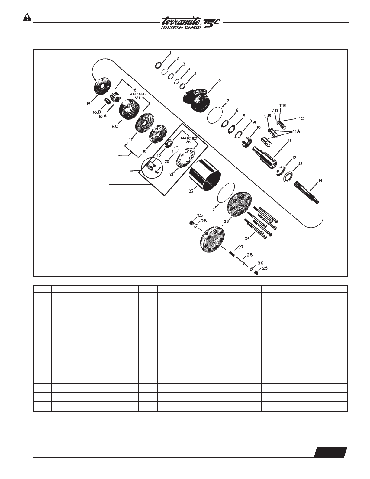
MAB/MAE Torquemotor Exploded Assembly View
Commentator and Ring
PN# 62008
PARTS MANUAL
Hydraulics
ITEM DESCRIPTION ITEM DESCRIPTION ITEM DESCRIPTION
1 Seal 11B Nut 17 Manifold Plate
2 Retaining Ring 11C Washer 18 Manifold
3 Back-Up Washer 11D Bolt 19 Commutator
4 Washer 11E Lock Washer 20 Seal Ring
5 Seal 12 Bearing 21 Commutator Ring
6 Housing 13 Thrust Bearing 22 Sleeve
7 Seal Ring (2) 14 Drive Link 23 End Cover Assembly
8 Thrust Washer 15 Wear Plate 24 Special Bolt (7)
8A Thrust Washer 16 Rotor Set 25 Plug
9 Thrust Bearing 16A Rotor 26 O-Ring
10 Bearing 16B Vane (7) 27 Sping
11 Coupling Shaft 16C Stator 28 Valve (Shuttle)
11A Key
1.800.428.3772
Intl. 1 .304.776.4231
Copyright © 2006 Terramite Corporation
WWW.TERRAMITE.COM/SAFETY
Charleston, WV/USA
2.15
Page 22
Read Operators Manual For Safety
Hydraulics
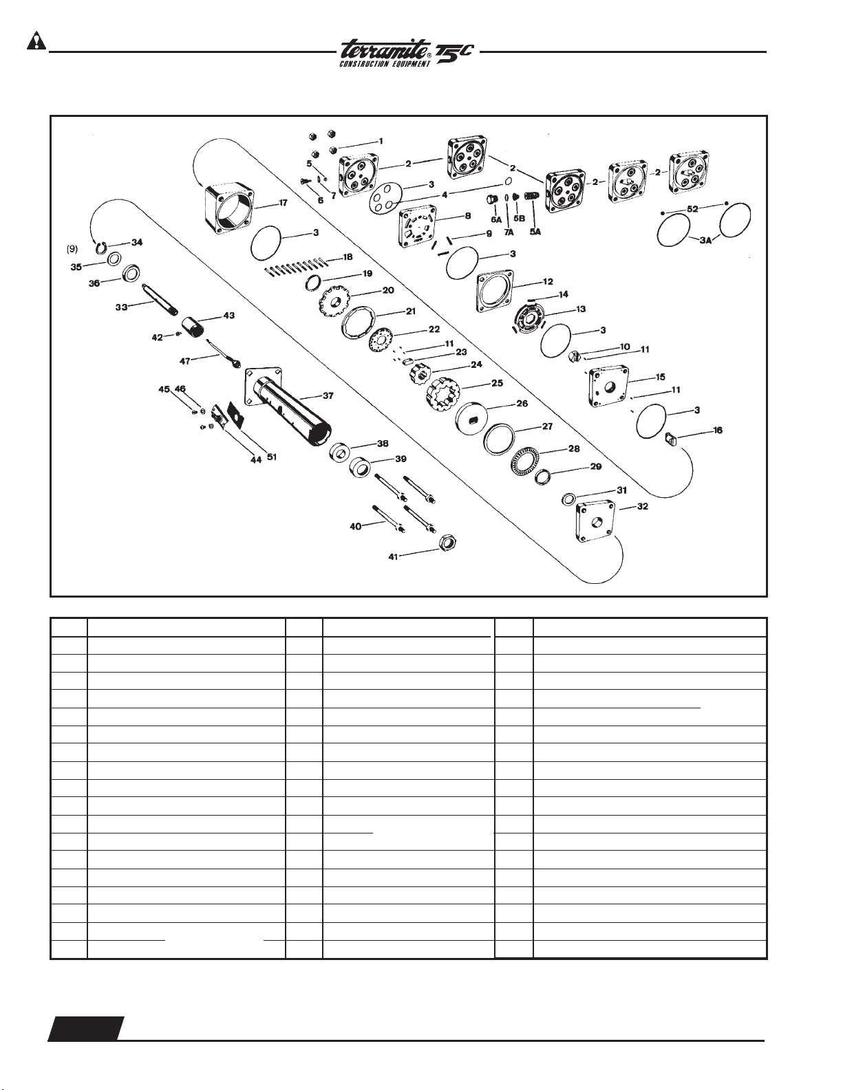
Power Steering Column Exploded Assembly View
PARTS MANUAL
ITEM DESCRIPTION
1 Nut 5/16 UNF 24 (4)
2 Port Cover
3 Seal Ring (5)
3A Seal Ring (White)
4 O'Ring (3), (4) or (5)
5 Ball-7/32 inch (6mm) dia.
5A Relief Valve Cartridge
5B Coil Spring
6 Plug
6A Hex Plug
7 O'Ring, Plug & O'Ring Assy.
7A O'Ring
8 Port Manifold
9 Spring, 3/4 inch (19mm) (3)
10 Hex Drive Assy.
11 Alignment Pin (Needle Brg.) (9)
12 Valve Ring
13 Valve Plate
Matched Set
}
ITEM DESCRIPTION
14 Spring, 1/2 Inch (13mm) (3)
15 Isolation Manifold
16 Drive Link
17 Metering Ring
18 Screw, Hex Socket Hd (11)
19 Seal, Commutator
20 Commutator Cover
21 Commutator Ring
22 Commutator
23 Spacer-Drive Link
24 Rotor
25 Stator
26 Drive Plate
27 Spacer-Trust Bearing
28 Thrust Bearing
29 Face Seal
31 Seal Spacer
32 Upper Cover Plate
Matched Set
}
ITEM DESCRIPTION
33 Input Shaft/Wheel Tube
34 Retaining Ring
35 Washer-Retaining Plate
36 Retaining Plate
37 Upper Cover & Jacket Assy.
38A7/8 Bushing
38B3/4Bushing
39 Seal
40 Special Bolt, 5/16 24UNF-2A
41 Nut
42 Screw
43 Contact Ring Assy.
44 Contact Brush Assy.
45 Screw & Lock Washer
46 Washer [for 11/2 inch (38 mm) Jacket]
47 Horn Wire Cable Assy.
51 Spacer [for 11/2 inch (38 mm) Jacket]
52 Ball 9/32 inch (22mm)
Items #44, 45, 46, 51 are not part of HGF service assembly unit. They must be
purchased as separate items of order.
Matched
}
Set
2.16
WWW.TERRAMITE.COM/SAFETY
Charleston, WV/USA
Copyright © 2006 Terramite Corporation
1.800.428.3772
Intl. 1 .304.776.4231
Page 23
Read Operators Manual For Safety
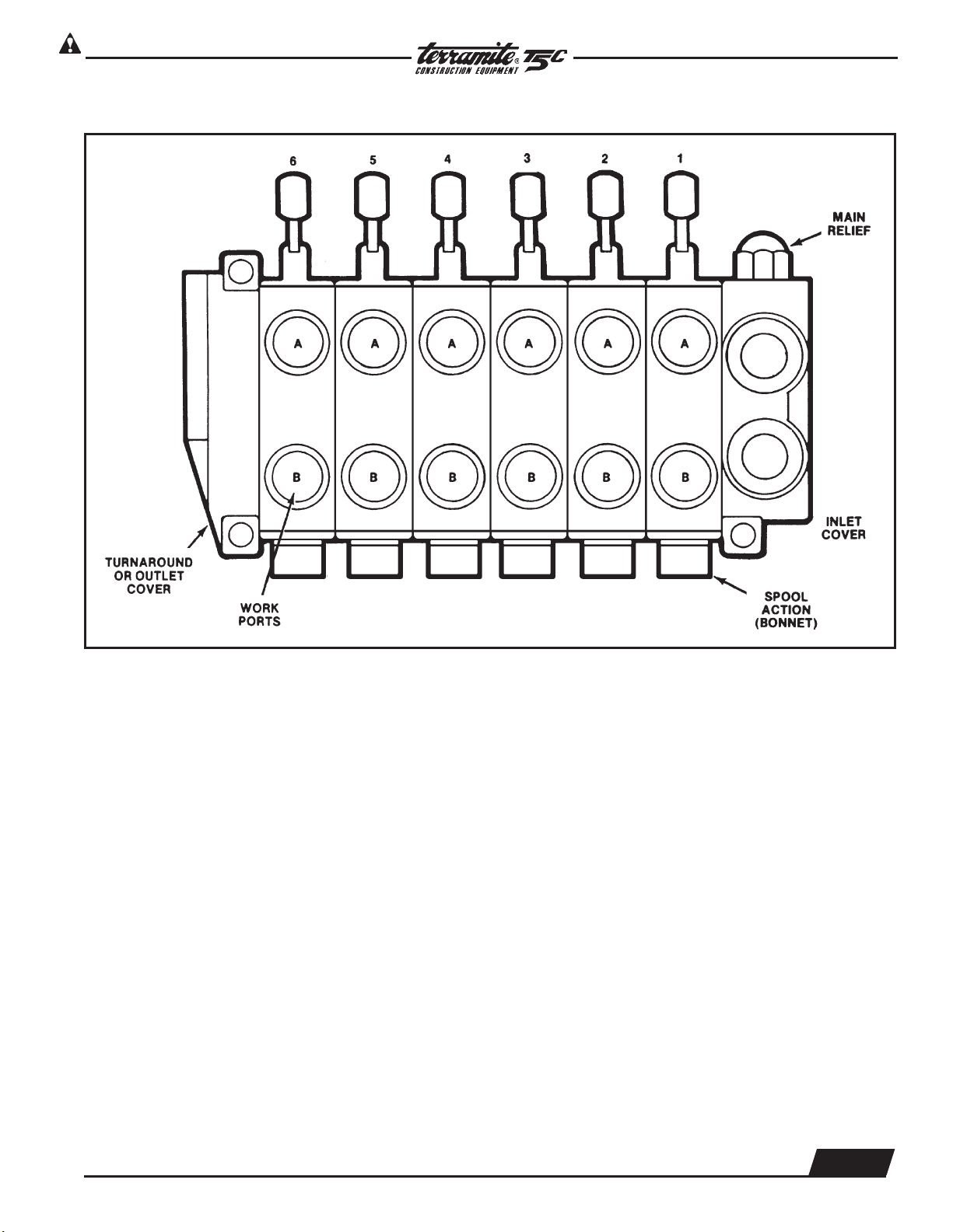
Schematic-View of Backhoe Control Valve Assembly
PARTS MANUAL
Hydraulics
1. Before disassembly, it is suggested that each valve section be marked numerically to avoid incorrect
reassembly.
2. Remove three assembly stud nuts from the left end section using a
3. Remove valve sections by sliding from assembly studs.
9
/16" thin wall socket.
1.800.428.3772
Intl. 1 .304.776.4231
WWW.TERRAMITE.COM/SAFETY
Copyright © 2006 Terramite Corporation
2.17
Charleston, WV/USA
Page 24
Read Operators Manual For Safety
Hydraulics
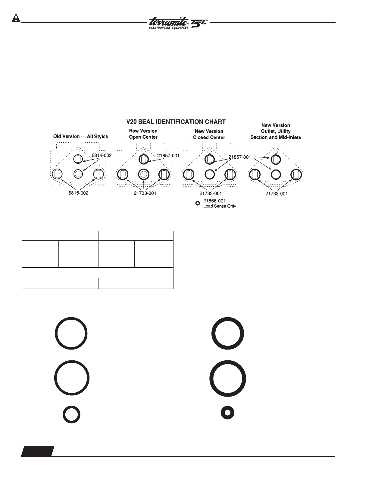
Parts Ordering Information
As of April 1, 1991, the section seals for the
V20 changed. The new versions have larger cross
section (old was .070, new is .103) and different configurations for open center and closed center sections. The old design utilized the same seals for all
versions (two .801 I.D. and two .926 I.D.). The new
design uses one configuration for open center (three
.924 I.D. and one .799 I.D.) and another configuration
PARTS MANUAL
for closed center, load sensing and all outlet covers
(two .924 I.D. and two .799 I.D., with one .237 I.D. for
load sensing).
The following charts is provided to aid in selection of the proper seals. It is important to note that
the seal kits include all O-rings (new and Old), therefore there will be some left unused.
The following section seals are included in the Kits:
Standard Kits Viton Kits
Old New Old New
(2)6814-002 (2)21867-001 (2)7450-001 (2)9003-117
(2)6815-002 (3)21733-001 (2)7451-001 (3)9002-119
Load sensing kits (additional seals)
(1)8316-001 (1)21866-001 (1)9002-011 (1)9002-108
OLD NEW
6814-002 ....... STD
7450-001 ....... VITON
6815-002 ....... STD
7451-001 ....... VITON
Seal kit changes.
K-6121 Section Seal Kit, One Section
K-6027 Complete Seal Kit, 3 or 4 Way Section
K-6028 Complete Seal Kit, 4 Way Float Section
K-6209 Complete Seal Kit, Series 3 or 4 Way Section
K-6210 Complete Seal Kit, Series 4 Way Float Section
K-6154 Complete Seal Kit, Load Sensing 4 Way Float
K-6155 Complete Seal Kit, Load Sensing 3 or 4 Way Section
K-6156 Section Seal Kit, Load Sensing-One Section
K-6160 Viton Section Seal Kit, One Section
*Complete Seal Kits include spool seals and O-rings for check plugs.
21867-001 ..... STD
9003-117 ....... VITON
21733-001 ..... STD
9002-119 ....... VITON
Seal Kit PN#85057 Prior to 1991
THESE SEALS ARE NOT INTERCHANGEABLE. OLD AND NEW STYLE SECTIONS MAY BE USED IN THE SAME ASSEMBLY
PROVIDED THE CORRECT SEALS ARE USED FOR EACH SECTION.
2.18
WWW.TERRAMITE.COM/SAFETY
Charleston, WV/USA
8316-001 ....... STD
9002-011 ....... VITON
Copyright © 2006 Terramite Corporation
Seal Kit PN#85058 After 1991
21866-001 ..... STD
9002-108 ....... VITON
1.800.428.3772
Intl. 1 .304.776.4231
Page 25

Read Operators Manual For Safety
PARTS MANUAL
Hydraulics
Loader Valve
Relief
Valve
Power
Beyond
Detent Assembly
1. Raise and Lower Control Section
2. Curl and Dump Section
1.800.428.3772
Intl. 1 .304.776.4231
Copyright © 2006 Terramite Corporation
WWW.TERRAMITE.COM/SAFETY
Charleston, WV/USA
2.19
Page 26
Read Operators Manual For Safety
Hydraulics
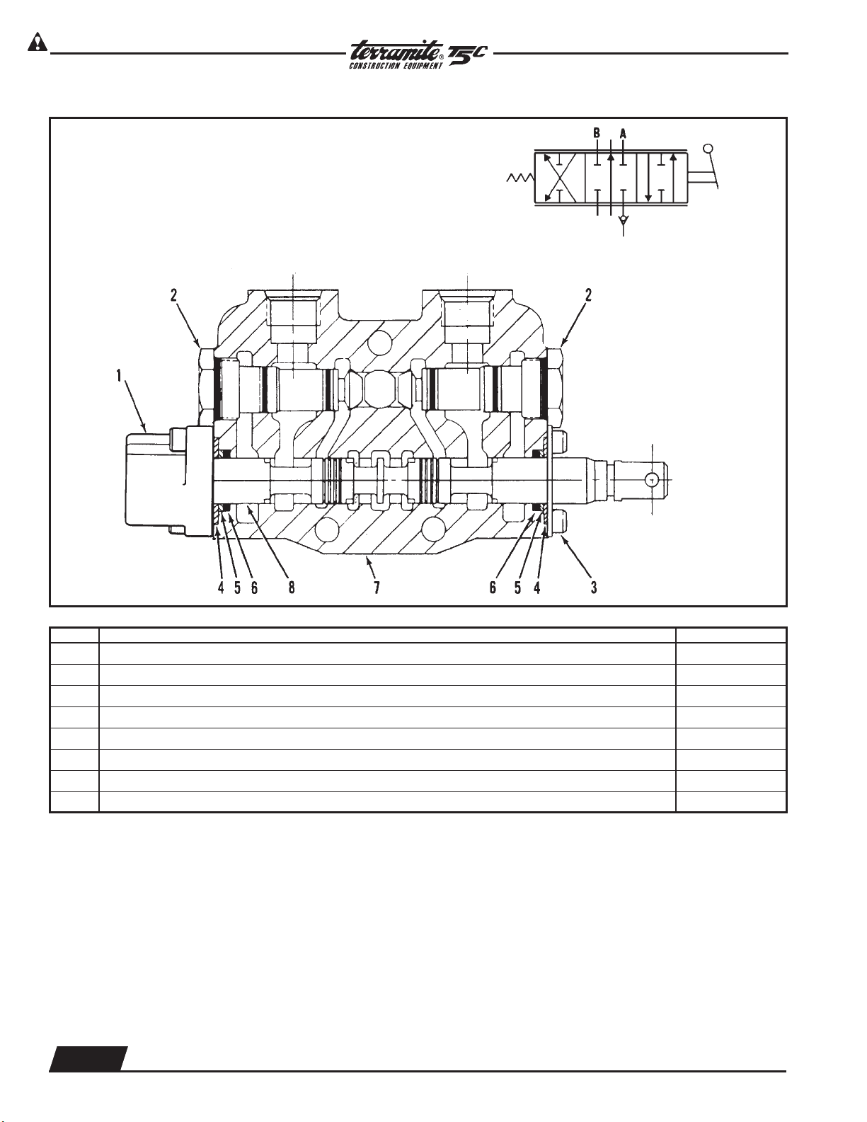
4-Way, 3-Position Valve Section
PARTS MANUAL
Torque to
10 ft. lbs. [13,6 Nm]
ITEM DESCRIPTION QTY. PER SECTION
1 Positioner, Spool, Standard 1
2 Check, Load 2
3 Retainer Assembly, Standard, Includes Screws 1
4 Retainer, Plate Washer 2
5 Washer, Back-Up (See Note 1) 2
6 Seal, O-Ring (See Note 1) 2
7 Housing, Standard (See Note 2) 1
8 Spool, 4-Way (See Note 2) 1
Notes:
1. Seal and washer not sold separately. Order Seal Kit.
2. These are matched parts and are not sold separately.
Buna-N seals are standard for all Gresen valve assemblies. Optional Viton seals are available.
2.20
WWW.TERRAMITE.COM/SAFETY
Charleston, WV/USA
Copyright © 2006 Terramite Corporation
1.800.428.3772
Intl. 1 .304.776.4231
Page 27
Read Operators Manual For Safety
PARTS MANUAL
Hydraulics
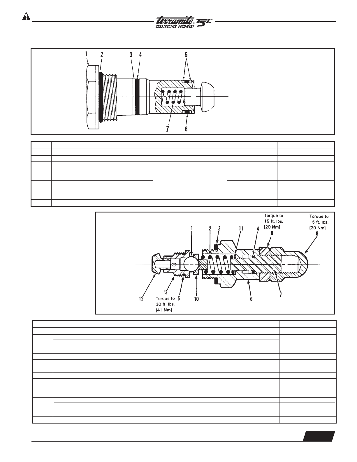
Load Check Plug Assembly
Torque Load Check Plug
Assembly to 20 ft. lbs. [27 Nm].
ITEM DESCRIPTION QTY. PER PLUG ASSEMBLY
Replacement Load Check Plug Assembly
Seal Kit, (Contains Items 2, 3, 4, 5 & 6)
1 Plug, Lift Check, Steel (Heavy Duty) 1
2 Seal, O-Ring 1
3 Washer, Back-Up, Outer 1
4 Seal, O-Ring, Outer 1
5 Washer, Back-Up, Inner 2
6 Seal, O-Ring 1
7 Spring, Lift Check 1
Not Sold Separately
}
For Installation: Torque Relief
Valves Assembly to 45 ft. lbs.
[61 Nm]
High Pressure
Relief
ITEM DESCRIPTION QTY. PER PLUG ASSEMBLY
1 Ball 1
2
3 Gasket, Relief Body 1
4 O-Ring, Adjusting Screw 1
5 O-Ring, Valve Seat 1
6 Body 1
7 Screw, Adjusting 1
8 Nut, Jam, Adjusting Screw 1
9 Nut, Acorn Cap 1
10 Guide, Spring 1
11
12 Poppet, Check 1
13 Seat, Valve 1
Spring, Relief (Models SPK & SSK only)
Spring, Relief (Models SPK & SSK only)
Washer, Spacer (SP) 1
Washer, Spacer (SPK) 2
1
1.800.428.3772
Intl. 1 .304.776.4231
WWW.TERRAMITE.COM/SAFETY
Copyright © 2006 Terramite Corporation
2.21
Charleston, WV/USA
Page 28

Read Operators Manual For Safety
Hydraulics
PARTS MANUAL
Terramite Suggests Keeping a Current Journal on Replacement Parts
for Quick Reference or Field Notes on Your Machine
_________________________________________________________
_________________________________________________________
_________________________________________________________
_________________________________________________________
_________________________________________________________
_________________________________________________________
_________________________________________________________
_________________________________________________________
_________________________________________________________
_________________________________________________________
_________________________________________________________
_________________________________________________________
_________________________________________________________
_________________________________________________________
_________________________________________________________
_________________________________________________________
_________________________________________________________
_________________________________________________________
_________________________________________________________
_________________________________________________________
_________________________________________________________
_________________________________________________________
_________________________________________________________
_________________________________________________________
_________________________________________________________
_________________________________________________________
_________________________________________________________
Remember to Read, Understand and Follow Your Operator's Hand-
book on Safety and the Correct Procedure for Safe Operation and
Handling of Your Compact Tractor Loader Backhoe.
2.22
WWW.TERRAMITE.COM/SAFETY
Charleston, WV/USA
Copyright © 2006 Terramite Corporation
1.800.428.3772
Intl. 1 .304.776.4231
Page 29

Read Operators Manual For Safety
Manual Box, Manual and Read Operator's Book First Must be on Machine
PARTS MANUAL
Components
1
Bolt
PN# 22008
13
2
7
6
Roll Pin
3
PN# 25000
5
10
Spring
PN# 14081
Washer
PN# 28956
8
Plate Welded
to Frame
4
ITEM PART NUMBER DESCRIPTION QTY.
1 11981 Seat Cushion, Back 1
2 11904 Seat Cushion, Bottom 1
3 14259 Seat Assembly, Swivel 1
4 11903 Seat Belt Assembly (Both Halves) 1
5 26000 Spring 1
6 14011 Handle 1
7 14066 Handle Assembly 1
22010 Nut 1" NF Z Jam 1
8
9 14062 Seat Rails with Handles - Not Shown 2
10 14063 Seat Rails 2
11 14013 Seat Assembly without Bearings - Not Shown 1
12 14219 Update Kit for Older Seats (Prior to 7-1-96) - Not Shown 1
13 11911 Manual Box 1
14 14046 Decal, Read Owner's Manual - See section four for decal information 1
22084 Washer/ Flat 1" USS #17962 1
53160 Cotter Pin 1
14018 Plastic Disc 1
Seat Swivel Bearing (Used Prior to 7-1-96)
ITEM PART NUMBER DESCRIPTION QTY.
NOT
SHOWN
NOT
SHOWN
14217 Seat Bearing Prior to 7-1-96 1
14219 Seat Assembly with Bearing Prior to 7-1-96 1
1.800.428.3772
Intl. 1 .304.776.4231
WWW.TERRAMITE.COM/SAFETY
Copyright © 2006 Terramite Corporation
3.1
Charleston, WV/USA
Page 30

Read Operators Manual For Safety
Components
Exploded View of Front End Loader
30
17
PARTS MANUAL
13
28
37
32
29
26
20
27
25
2
27
19
33
2
11
14
7
34
36
4
1
25
31
38
39
22
35
3.2
16
28
WWW.TERRAMITE.COM/SAFETY
Charleston, WV/USA
24
26
Copyright © 2006 Terramite Corporation
10
12
6
40
5
23
3
1.800.428.3772
Intl. 1 .304.776.4231
Page 31

Read Operators Manual For Safety
PARTS MANUAL
Components
ITEM PART NUMBER DESCRIPTION QTY.
1
2 22500 Arm Cylinder 2
3
4 53212 Axle Weldment after SN 5960601 1
5
6 15013 Bolts 2
7 53220 Bumper 1
8 22146 Bumper Bolts 2
9 28500 Bumper Nuts 2
10
11 20177 Button Fittings, Hydraulic 26
12
13
14 23174 Fitting, 1/4" x 45° 2
15 20174 Fitting, 1/4", Hydraulic Hose (Not Shown) 26
16 21428 Fitting, Grease 32
17 23100 Front Curl Cylinder 1
18 15600 Grill Assembly (Not Shown) 1
19 77072 Headlight Assembly 1
20 12062 Loader Arm Assembly(resale) 1
21 42023 Muffler, 20 HP Kohler Engine (Not Shown) 1
22
23 20082 Nut, 3/8" NC Flange 24
24 28504 Nuts 2
25 13200 Pin, 1" x 43/4" Loader Bucket 2
26 12600 Pin, 1" x 51/4", Arm Cylinder 2
27 13000 Pin, 1" x 51/4", Front Curl Cylinder 2
28 12300 Pin, 1" x 67/8", Loader Arm 2
29 12301 Pin, 1" x 77/8", Arm Cylinder Rod 2
30 23101 Rod, F. Curl 1
31
32 11282 Safety Fuel Cap 1
33
34 53103 Spindle, L 11/4" prior to SN 5960601 1
35 53114 Spindle, R 13/4" after SN 5960601 1
36
37 15500 Tank, Fuel 1
38
39
40 24008 Washers 2
13300 48" Loader Bucket
13356 56" Loader Bucket
15405 Axle Pin 11/8"
15407 Axle Pin 11/4"
53075 Axle Weldment prior to SN 5960601
53201 Axle Weldment
53090 Bearing, Thrust prior to SN 5960601
53091 Bearing, Thrust after SN 5960601
53106 Bushing Spindle after SN 5960601
53175 Bushing Spindle
53081 Castle Nut 11/4" I.D.
53080 Castle Nut 11/8" I.D.
13303 Cutting Edge 48" (Weld-on)
13056 Cutting Edge 56" (Weld-on)
28502 Nut, 1/2" NF Jam prior to SN 5960601
28503 Nut, 5/8" NF Jam after SN 5960601
25801 Rod, Power Steering prior to SN 5960601
25803 Rod, Power Steering after SN 5960601
26500 Screw, Set prior to SN 5960601
28501 Screw, Set after SN 5960601
53050 Spindle, L
53104 Spindle, L 13/4" after SN 5960601
53113 Spindle, R 11/4" prior to SN 5960601
53116 Spindle, R
25815 Steering Cylinder prior to SN 2150180
81212 Steering Cylinder after SN 2150180
53053 Tie Rod prior to SN 5960601
53054 Tie Rod after SN 5960601
53042 Tie Rod End prior to SN 5960601
53043 Tie Rod End after SN 5960601
1
1
2
2
1
1
1
1
4
1
2
2
1.800.428.3772
Intl. 1 .304.776.4231
WWW.TERRAMITE.COM/SAFETY
Copyright © 2006 Terramite Corporation
3.3
Charleston, WV/USA
Page 32

Read Operators Manual For Safety
Components
Exploded View of Dash
26
23034
12
PARTS MANUAL
11
10
25
9
8
13
7
Before 3/2006
14
16
3
2
4
77080
27
77062
16085
15
6
5
22045
1
14801
18
23
13072
20
24
19
22045
17
22
21
ENGINE PART NUMBER DESCRIPTION QTY.
Kohler 15123 Hood Assembly with Decals
Honda 15128 Hood Assembly with Decals 1
11
Perkins 15124 Hood Assembly with Decals
Kubota 15125 Hood Assembly with Decals
3.4
WWW.TERRAMITE.COM/SAFETY
Charleston, WV/USA
Copyright © 2006 Terramite Corporation
1.800.428.3772
Intl. 1 .304.776.4231
Page 33

Read Operators Manual For Safety
PARTS MANUAL
Components
13003
27
1
3
13072
77080
77080
After 3/2006
ITEM PART NUMBER DESCRIPTION QTY.
1 13142 Throttle Cable 1
2 77033 Ignition Switch w/Key (3 Prong) Before 5-98 Processing Requires Serial Number 1
3 70036 Ignition Switch w/Key (6 Prong) After 5-98 Processing Requires Serial Number
4 15100 Steering Gear, Power 1
5 21002 Filter, Hydraulic (Not Shown) 1
6 15900 Tank, Hydraulic, T5 (Not Shown) 1
7 56002 Brake Lever, Adjustable 1
8 28751 Nut, Headlamp 8
9 77072 Headlamp assembly 2
10 15501 Fitting, Fuel Tank, 1/8 MP x 1/4" HB 90o (specify engine model) 1
11 72015 See Wiring Harness & order by engine type 1
12 28208 Bolt, 1/2" x 11/4"2
13 15032 Hood, Hinge, Bushing, T5c/T7/T9 (Not Shown) 2
14 22204 Cap, Hyd. Breather Filter w/Dipstick 1
15 15700 Deck Center 1
16 10160 T5 and T5B Old Style Dipstick (Not Shown) 1
17 11600 Foot Pedal 1
18 11627 Pillow Block Bearing 1
19 11629 Spring Centering Bolt 1
20 13029 Pedal Spring 1
21 11610 Pedal Block 1
22 11620 Pedal Shaft 1
23 22184 Pedal Stop Bolt 1
24 Factory Insalled 4 POINT ROPS mount - Weld on type (standard Equipment After 1-1-97)
15425 Bolt on Reto Fit 4 POINT ROPS Kit (Requires Drilling)
25 13942 Wobblestick Knob 1
26 13136 Cap Steering Wheel 1
27 14801 Choke Cable 1
1.800.428.3772
Intl. 1 .304.776.4231
WWW.TERRAMITE.COM/SAFETY
Copyright © 2006 Terramite Corporation
3.5
Charleston, WV/USA
Page 34

Read Operators Manual For Safety
Components
Under the Hood - Kohler Command Engine
PARTS MANUAL
3
4
7
2
6
3.6
WWW.TERRAMITE.COM/SAFETY
Charleston, WV/USA
1
Copyright © 2006 Terramite Corporation
5
1.800.428.3772
Intl. 1 .304.776.4231
Page 35

Read Operators Manual For Safety
PARTS MANUAL
Components
ITEM PART NUMBER DESCRIPTION QTY.
1 13142 Throttle Cable 1
2 84000
80033
3 15501 Fitting, Fuel Tank, 1/8 MP x 1/4" HB 90o (specify engine model) 1
4 15502 Clamp, Fuel Hose 5
5 15503
15506
6 22027 Hood Prop Bolt 1
7 42023 20HP Kohler Engine Muffler 1
1
/4" Fuel Hose (Sold by the Foot) 3
5
/16" Fuel Hose (Sold by the Foot)
1
/4" Fuel Filter 1
5
/16" Fuel Filter
View of Drive Shaft Coupler
1
ITEM PART NUMBER DESCRIPTION QTY.
1 60033 Drive Shaft Coupler used after 1-91 Key Wayed 1
NOT
SHOWN
61622 UCC Sleeve Coupling used prior to 1-91 1
60001 4WD (Set Screw on Engine end only) 1
2 60040 Drive Shaft Splined L3 Tooth after 2450222 1
3 60035 Drive Shaft Assy, Slined, T5C\7\9 2WD 1
1.800.428.3772
Intl. 1 .304.776.4231
WWW.TERRAMITE.COM/SAFETY
Copyright © 2006 Terramite Corporation
3.7
Charleston, WV/USA
Page 36

Read Operators Manual For Safety
Components
View from Behind Center Steer
After April 2006
28
77290
PARTS MANUAL
72028
13
21428
17
25500
Next to Linkage
8
13965
13949
13995
5
21
24
Battery -
Not for Resale
7
4
9
13943
31
3
85036
36
88835
3.8
32
88462
34
88466
88483
35
88463
33
WWW.TERRAMITE.COM/SAFETY
Charleston, WV/USA
15
22284
Copyright © 2006 Terramite Corporation
14
22278
1.800.428.3772
Intl. 1 .304.776.4231
Page 37

Read Operators Manual For Safety
PARTS MANUAL
Components
ITEM PART NUMBER DESCRIPTION QTY.
3 13413 Cotter Pin 7
4 13943 Relief Valve, Loader 1
5 13944 Wobblestick Pivot Block, Front 1
7 13949 Wobblestick Hinge Bolt Support 1
8 13965 Linkage 3
9 13995 Wobblestick Hinge Bolt 1
13 21428 Fitting, Grease 32 Per Machine
14 22278 Fitting, 1/2" x 90°, Loader Valve 1
15 22784 Fitting, 1/2" x 1/4" x 90°, Loader Valve 4
17 25500 Nut, 5/16" NF Jam 3
21 72038 48" Cable, Battery to Solenoid 1
24 77022 Battery (not for resale for shipments) 1
28 77290 Insulator, Red 1
31 85036 Kit, Linkage Valve 1
32 88462 Hose, 1/4" x 62", Loader Valve 1
33 88463 Hose, 1/4" x 63", Loader Valve 1
34 88466 Hose, 1/4" x 66", Loader Valve 1
35 88483 Hose, 1/4" x 83", Loader Valve 1
36 88835 Hose, 1/2" x 35", Loader Valve 1
All Hoses Must Be 5000 psi rated, 20,000 Burst 2 Wire
Braid Rubber Covered.
1/2 FX08 1/2 ID E-Z Flex 250 MSHA IC - 123/10 Exceeds SAE 3500psi MAX
3/8 FX06 3/8 ID E-Z Flex 250 MSHA IC - 123/10 Exceeds SAE 4000psi MAX
1/4 FX04 1/4 ID E-Z Flex 250 MSHA 2G-IC-20C/1 Exceeds SAE 5000psi MAX
1.800.428.3772
Intl. 1 .304.776.4231
WWW.TERRAMITE.COM/SAFETY
Copyright © 2006 Terramite Corporation
3.9
Charleston, WV/USA
Page 38

Read Operators Manual For Safety
Components
View from Behind Dash
Before April 2006
PARTS MANUAL
27
11
12
20
1
17
Next to Linkage
24
Battery - Not for Resale
77033 or 70036
25
28
23
21
26
7
19
13142
9
5
13
2
16
6
8
4
29 30
Ground Wire
31
36
3
22
18
3.10
34
WWW.TERRAMITE.COM/SAFETY
Charleston, WV/USA
32
35
Copyright © 2006 Terramite Corporation
15
33
14
10
1.800.428.3772
Intl. 1 .304.776.4231
Page 39

Read Operators Manual For Safety
PARTS MANUAL
Components
ITEM PART NUMBER DESCRIPTION QTY.
1 13072 Handle, Loader Wobblestick 1
2 13411 Valve Link 3
3 13413 Cotter Pin 7
4 13943 Relief Valve, Loader 1
5 13944 Wobblestick Pivot Block, Front 1
6 13947 “L” Link 1
7 13949 Wobblestick Hinge Bolt Support 1
8 13965 Linkage 3
9 13995 Wobblestick Hinge Bolt 1
10 14801 Choke Cable 1
11 15417 Bracket, Battery 1
12 20082 Nut, 3/8" NC Flange Z 1
13 21428 Fitting, Grease 32 Per Machine
14 22278 Fitting, 1/2" x 90°, Loader Valve 1
15 22784 Fitting, 1/2" x 1/4" x 90°, Loader Valve 4
16 23008 Nut, 3/8" - 24" NF Lock 1
17 25500 Nut, 5/16" NF Jam 3
18 40014 ASCO Fuel Shutoff Valve Assembly 1
19 70033 Holder, Fuse, 20 AMP, ATO 1
20 72028 7" Cable, Battery to Ground 1
21 72038 48" Cable, Battery to Solenoid 1
22 72076 ASCO Fuel Shutoff Valve 1
23 73695 Toggle Switch Back Boot Cover 1
24 77022 Battery (not for resale for shipments) 1
25 77062 Single Pole Toggle Switch 1
26 77080 Hourmeter (view from back) 1
27 77280 Insulator, Black 1
28 77290 Insulator, Red 1
29 84070 Valve, Loader(With Fittings) 1
30 85015 Valve, Loader 1
31 85036 Kit, Linkage Valve 1
32 88462 Hose, 1/4" x 62", Loader Valve 1
33 88463 Hose, 1/4" x 63", Loader Valve 1
34 88466 Hose, 1/4" x 66", Loader Valve 1
35 88483 Hose, 1/4" x 83", Loader Valve 1
36 88835 Hose, 1/2" x 35", Loader Valve 1
All Hoses Must Be 5000 psi rated, 20,000 Burst 2 Wire
Braid Rubber Covered.
1/2 FX08 1/2 ID E-Z Flex 250 MSHA IC - 123/10 Exceeds SAE 3500psi MAX
3/8 FX06 3/8 ID E-Z Flex 250 MSHA IC - 123/10 Exceeds SAE 4000psi MAX
1/4 FX04 1/4 ID E-Z Flex 250 MSHA 2G-IC-20C/1 Exceeds SAE 5000psi MAX
1.800.428.3772
Intl. 1 .304.776.4231
WWW.TERRAMITE.COM/SAFETY
Copyright © 2006 Terramite Corporation
3.11
Charleston, WV/USA
Page 40

Read Operators Manual For Safety
Components
PARTS MANUAL
Front Wheel Hubs
1
ITEM PART NUMBER DESCRIPTION QTY.
2
1 53130 Hub, previous to 6-1-96 2
2 53137 Hub, 5 on 4 after 6-1-96 2
Hub Assembly and Spindle
1
NOTE: THESE PART NUMBERS USED ON MACHINES BUILT AFTER 6-96. WHEN ORDERING, SUPPLY SERIAL NUMBER OF
ITEM PART NUMBER DESCRIPTION QTY.
1 53170 Dust Cap 1
2 53160 Cotter Pin 1
3 53150 Nut 1
4
53057 Bearing, Outer Before 6-96
53125 Bearing, Outer After 6-96
5 53140 Washer 1
6 53137 Hub, 5 on 4 after 6-1-96 1
7
8
9
53058 Race, Outer & Inner Before 6-96
53124 Race, Inner After 6-96
53057 Bearing, Inner Before 6-96
53123 Bearing, Inner After 6-96
53055 Seal Before 6-96
53111 Seal After 6-96
2 3
4 5
YOUR MACHINE.
6
7
8 9
1
1
1
1
3.12
WWW.TERRAMITE.COM/SAFETY
Charleston, WV/USA
Copyright © 2006 Terramite Corporation
1.800.428.3772
Intl. 1 .304.776.4231
Page 41

Read Operators Manual For Safety
PARTS MANUAL
Components
Left Front Tire and Rim (Prior to 3-03)
1
4
3
2
5
Left Rear Tire and Rim
9
8
7
ITEM PART NUMBER DESCRIPTION QTY.
1 51272 Tire, 20.5 x 8 x 10 2
2 53170 Dust Cap 2
3 51273 Tire Valve 2
4 28505 Nut, 3/8" NF Lug 10
5
6
51292
52871 5 Lug after SN 5960601 (painted)
Rim, Front
51005 Front Tube (not shown) 2
4 Lug prior to SN 5960601
2
51172 Std. Rear Tire
Mounted on 9.5"x16" Rim (1-18.2) used
7
51721 Std. Rear Tire
51722 Std. Rear Tire
8
51182
51184 after 2003
Rim
prior to 11-95
Mounted on 9.5"x16" Rim (1-18.4)
used after 11-95
prior to 11/1/95
2
2
9 28506 Nut, Lug 10
10 51000 Rear Tube (not shown) 2
1.800.428.3772
Intl. 1 .304.776.4231
WWW.TERRAMITE.COM/SAFETY
Copyright © 2006 Terramite Corporation
3.13
Charleston, WV/USA
Page 42

Read Operators Manual For Safety
Components
Top View of Parking Brake Assembly
PARTS MANUAL
PN # 16054
PN # 22035
PN # 16053
1
8
9
7
6
5 4 3
2
10
NOT SHOWN
ATTACHES TO BRAKE BAND
ITEM PART NUMBER DESCRIPTION QTY.
1 55620 Brake Band 1
2 55606 Brake Cable 1
3 55613 Brake Off Set Link Not Shown - Attaches to Brake Band 1
4 64003 Drive Motor 1
5 51800 Drive Motor Flange 1
6 22034 Bolt 1
7 28500 Nut 1
8 23005 Nut 1
9 22038 Bolt 1
17028 Bushing, Brake 9/16" ID x 1" OD x 7/8" L 1
10 17029 Bushing, Brake 9/16" ID x 1"OD x 1 1/4" L 1
22042 Bolt, 14mm x 90 mm C2.0z Brake 38748 1
3.14
WWW.TERRAMITE.COM/SAFETY
Charleston, WV/USA
Copyright © 2006 Terramite Corporation
1.800.428.3772
Intl. 1 .304.776.4231
Page 43

Read Operators Manual For Safety
Retro Fit Parking Brake Spring Assembly
1
3
PARTS MANUAL
Components
55620
2
4
55613
PART NUMBER DESCRIPTION QTY.
1 13168 Spring, Retro Fit Parking Brake 1
2 55621 Spring Bracket, Parking Brake 1
1.800.428.3772
Intl. 1 .304.776.4231
WWW.TERRAMITE.COM/SAFETY
Copyright © 2006 Terramite Corporation
3.15
Charleston, WV/USA
Page 44

Read Operators Manual For Safety
Components
View from Front of Rear Axle - Parking Brake Assembly
1
PARTS MANUAL
6
4
ITEM PART NUMBER DESCRIPTION QTY.
1
55002 Rear Axle prior to 10-1-95
55004 Rear Axle after 10-1-95
35
2
1
2 51800 Drive Motor Flange 1
3 26288 Bolt, 3/8" x 13/4" NF GR8 4
4 62021 Key 1/4" x 1/4" x 13/8"1
5 57034 Brake Drum 1
6 23008 Nut 1
3.16
WWW.TERRAMITE.COM/SAFETY
Charleston, WV/USA
Copyright © 2006 Terramite Corporation
1.800.428.3772
Intl. 1 .304.776.4231
Page 45

Read Operators Manual For Safety
PARTS MANUAL
Components
Exploded View of Dipstick
2
12
PN 10013 Bushing
1.25" ID x 1.5" OD x 2"
PN 17002
Bushing 1.25" ID x 1.5" OD x 3"
3
10
11
PN 19479 Quick Attach
Center Assembly
7
9
6
Bushing 1.25" OD x 1" ID x 3"
PN 10260
PN 17269
6 1/2" Pin
PN 17273
Quick Attach Pull Pin
1
5
8
4
ITEM PART NUMBER DESCRIPTION QTY.
1 10116 16” Bucket (Standard) 1
2 10268 Dipstick Assembly (resale) 1
3 10500 Tooth Cap after 1-90 NA
4 10510 Tooth Shank (Weld On) NA
5 10530 Pin, Tooth after 1-90 NA
6 10812 Pin, 11/4" x 71/2" 1
7 17013 Pin, 1" x 73/8" 1
8 17190 Pin, 11/4" x 81/4" 1
9 18240 Linkage Assembly Center; T5C 1
10 18260 Linkage Link Assembly T5C Left Assembly 1
11 18261 Linkage Link Assembly T5C Right Assembly
12 18270 Dipstick For Linkage Type Only 1
1.800.428.3772
Intl. 1 .304.776.4231
Copyright © 2006 Terramite Corporation
WWW.TERRAMITE.COM/SAFETY
Charleston, WV/USA
3.17
Page 46

Read Operators Manual For Safety
Components
Backhoe Assembly
PARTS MANUAL
5
36
18
30
42
31
32
20
26 27
11 21
21201 Rod
25
9
2
7
19
6
34
24
81048
Rod
23
3.18
35
29
21601
10 16 17
15
WWW.TERRAMITE.COM/SAFETY
Charleston, WV/USA
Rod
13 14
8
12
3
Copyright © 2006 Terramite Corporation
4
22
1.800.428.3772
Intl. 1 .304.776.4231
Page 47

Read Operators Manual For Safety
PARTS MANUAL
Components
ITEM PART NUMBER DESCRIPTION QTY.
1 10013 Boom Bushings 2
2 10286 Boom Assembly (resale) 1
3 10400 Pin, 11/4" x 81/4" 2
4 10410 Pin, 1" x 73/4" 1
5 10700 Pin, 1" x 67/8" 2
6 10701 Pin, 11/4" x 71/4" 1
7 10900 Boom Assembly 1
8 11006 Swing Stop 2
9 11100 Pin, 1" x 61/4" 6
10 11123 Guard, Outrigger 2
11 11140 Pin, Main Swing 1
12 11300 Swing Assembly 1
13 11500 Outrigger Assembly 4 Lug Prior to 5-1-96 2
14 11501 Outrigger Assembly 5 Lug after 5-1-96
15 11502 Pin, 1" x 41/8" 2
16 11510 Guard, Outrigger 2
17 11511 Outrigger Guard with pin 2
18 12019 Rod, Swing Cylinder Boss Only
19 14022 Reflector, Red 3
20 15300 Pin, 1" x 41/8" 2
21 17002 Bushing 1
22 17273 Pin, 1" x 9" 1
23 20082 Nut, 3/8" NC Flange 24
24 20174 Fitting, 1/4" 26
25 21000 Crowd Cylinder 1
21201 Rod, Crowd Cyl. 1
26 21200 Boom Cylinder 1
27 21201 Rod, Boom Cylinder 1
28 21420 Cotter Pin 2
29 21600 Outrigger Cylinder Before 3-3-99 2
30 25201 Rod, Swing Cylinder 1
31 28500 Nut, 1/2" NC Lock 1
32 28950 Washer 1
33 80045 Hose, 1/4" Swing Crossover, 15" 2
34 81060 Rear Curl Cylinder For Linkage Type T5C/T7 1
81048 Rod\Rear Cur Link 1
35 81139 Outrigger Cylinder After 3-3-99
36 82070 Cylinder Assembly, Swing W/Tee Fitting 2
37 84131 Hose, 1/4" x 131" (Not pictured) 1
38 88420 Hose, 1/4" Swing to Valve, 20" (Not pictured) 1
39 88425 Hose, 1/4" Swing to Valve, 25" (Not pictured) 1
40 88466 Hose, 1/4" x 66" (Not pictured) 3
41 88492 Hose, 1/4" x 92", crowd cylinder (Not pictured) 1
42 17020 Pin 6 5/8" Swing Cylinder To Frame 2
1.800.428.3772
Intl. 1 .304.776.4231
WWW.TERRAMITE.COM/SAFETY
Copyright © 2006 Terramite Corporation
3.19
Charleston, WV/USA
Page 48

Read Operators Manual For Safety
Components
PARTS MANUAL
Rear Axle Assembly
ITEM NUMBER DESCRIPTION PART NO. QTY.
PART DANA
1 55010 Housing-Axle * 1
2 64004 Gear & Pinion Ass'y-Drive * 1
3 55030 Kit-Inner Pinion Bearing 706031X 1
4 55040 Shim-Drive Pinion Adjusting * 1
5 55050 Baffle-Pinion Bearing * 1
6 55060 Shim-Pinion Bearing Adjusting * 1
7 55022 Kit-Outer Pinion Bearing 706030X 1
8 55080 Slinger-Pinion Bearing Outer * 1
9 55090 Seal-Pinion 35723 1
10 55100 End Yoke Assembly 3-4-5761X 1
Continued On Next Page
3.20
WWW.TERRAMITE.COM/SAFETY
Charleston, WV/USA
Copyright © 2006 Terramite Corporation
1.800.428.3772
Intl. 1 .304.776.4231
Page 49

Read Operators Manual For Safety
Rear Axle Assembly (Continued)
PARTS MANUAL
Components
ITEM NUMBER PART NUMBER DESCRIPTION PART NO. QTY.
PART PREVIOUS DANA
11 55110 5-11 Washer-Pinion Nut 30186 1
12 55120 5-12 Nut-Pinion 30185 1
13 55130 5-13 Companion Flange Assembly 2-1-1881X 1
14 55140 5-14 Cover-Carrier * 1
15 55150 5-15 Gasket-Carrier Cover 34685 1
16 55160 5-16 Plug-Cover 36472 1
17 55170 5-17 Bolt-Carrier Cover 34279
18 55180 5-18 Cap-Differential Bearing ** 1
19 55190 5-19 Bolt-Differential Bearing Cap 500400-20 2
20 55200 5-20 Kit-Differential Bearing 706032X 1
21 55210 5-21 Shim-Differential Bearing * 1
22 55220 5-22 Case-Differential * 1
23 55230 5-23 Bolt-Drive Gear 30187
24 55240 5-24 Pinion-Differential * 2
25 55250 5-25 Gear-Differential * 2
26 55260 5-26 Thrust Washer-Differential Pinion * 2
27 55270 5-27 Thrust Washer-Differential Gear * 2
28 55280 5-28 Shaft-Differential * 1
29 55290 5-29 Lock-Differential Shaft 13449 1
30 55300 5-30 Bolt-Break Mounting 34616-1 6
31 55310 5-31 Nut-Brake Mounting 35704 6
32 55320 5-32 Seal-Shaft Inboard 34419 2
33 55330 5-33 Ring-Wheel Bearing Retaining 32755 2
34 55340 5-34 Bearing Assembly 565903 2
35 55350 5-35 Seal-Shaft Outboard 35239 2
36 55360 5-36 Retainer-Oil Seal 35490 2
37 55370 5-37 Shaft-Axle Flanged * 2
38 55380 5-38 Bolt-Wheel 35491 10
LIMITED SLIP DIFFERENTIAL (TRAC-LOK) STD. ON SER #9975236 & UP
39 55390 5-39 Case-Differential * 1
40 55400 5-40 Gear-Differential * 2
41 55410 5-41 Shaft-Differential * 1
42 55420 5-42 Ring-Snap * 2
43 55430 5-43 Spacer-Differential Gear (Dished) *
44 55440 5-44 Plate-Differential *
45 55450 5-45 Disc-Differential *
46 55460 5-46 Plate-Differential (Selective Thickness) *
47 55470 5-47 Clip-Differential Clutch Retainer * 1
*SOLD IN KITS FORM ONLY FROM DANA
1.800.428.3772
Intl. 1 .304.776.4231
WWW.TERRAMITE.COM/SAFETY
Copyright © 2006 Terramite Corporation
3.21
Charleston, WV/USA
Page 50

Read Operators Manual For Safety
Components
PARTS MANUAL
Model T5C - Pin Schematic
1
2
4
3
15
6
5
7
17
16
3.22
8
WWW.TERRAMITE.COM/SAFETY
Charleston, WV/USA
14
10
13
Copyright © 2006 Terramite Corporation
9
12
11
1.800.428.3772
Intl. 1 .304.776.4231
Page 51

Read Operators Manual For Safety
PARTS MANUAL
Components
General Tightening Torque for Bolts, Nuts and Taperlock Studs
The following charts give the standard torque values for bolts, nuts and taperlock studs for SAE
Grade 5 or better quality.
Use these torques for bolts and nuts with
standard threads (conversions are approximate).
standard thread
Metric Fasteners
Thread
Size Standard Torque
Inches Lb. Ft. N.m*
1/4 9 ± 3 12 ± 4
5/16 18 ± 5 25 ± 7
3/8 32 ± 5 45 ± 7
7/16 50 ± 10 70 ± 15
1/2 75 ± 10 100 ± 15
9/16 110 ± 15 150 ± 20
5/8 150 ± 20 200 ± 25
3/4 265 ± 35 360 ± 50
7/8 420 ± 60 570 ± 80
1-/ 640 ± 80 875 ± 100
1-1/8 800 ± 100 1100 ± 150
1-1/4 1000 ± 120 1350 ± 175
1-3/8 1200 ± 150 1600 ± 200
1-1/2 1500 ± 200 2000 ± 275
*1 newton meter (N.m) is approximately the same as 0.1 mkg.
[Usually, material strength identification on
bolt head is with number (i.e., 8.8, 10.9, etc.)]
The chart on the right gives the torque for
bolts and nuts with Grade 8.8.
NOTICE: Caution must be taken to avoid
mixing metric and standard (customary)
fasteners. Mismatched or incorrect fasteners
can result in vehicle damage or malfunction,
or possible personal injury. Original fasteners
removed from the vehicle should be saved
for assembly when possible. If new ones are
required, caution must be taken to replace
with one that is of same part no. and grade
or better.
Metric ISO Thread
Thread
Size Torque
(mm) (N-m*) (Lb. Ft.)
M6 12 ± 4 9 ± 3
M8 25 ± 7 18 ± 5
M10 55 ± 10 40 ± 7
M12 95 ± 15 70 ± 10
M14 150±20 110±15
M16 220 ± 30 160 ± 20
M18 325 ± 50 240 ± 35
M20 450 ± 70 330 ± 50
M22 600 ± 90 440 ± 65
M24 775 ± 100 570 ± 75
M27 1150 ± 150 840 ± 110
M30 1610 ± 200 1175 ± 150
M33 2000 ± 275 1450 ± 200
M36 2700 ± 400 2000 ± 300
ISO - International Standard Organization
*1 newton meter (N.m) is approximately the same as 0.1 mkg.
1.800.428.3772
Intl. 1 .304.776.4231
WWW.TERRAMITE.COM/SAFETY
Copyright © 2006 Terramite Corporation
3.23
Charleston, WV/USA
Page 52

Read Operators Manual For Safety
Components
All Safety Decals Must Be On The Machine And Clearly Legible!
Decal Location - Right Side from Operators Position
4
2
1
9
PARTS MANUAL
DECAL SETS
Less Serial Plate
& Wobble Control
T1------------- 14169
T2------------- 14170
5
6
4
T3------------- 14171
T3-15 -------- 14172
T4------------- 14173
T5------------- 14174
7
T5B ---------- 14175
T5C ---- Gas 14176
T5C - Diesel 14177
2
3
8
1
6 8
ITEM PART NUMBER DESCRIPTION QTY.
2
3
7
4
5
9
1 14226 Decal, Digging Depth 8'4" 2
2 14004 Decal, Stand Clear 4
3 14055 Decal, Small Terramite 4
4 14057 Decal, T5C 4
5 14322 Decal, Plate ROPS T5&T6 Series 1
6 14001 Decal, Large Terramite 2
7 14099 Decal, American Flag 2
8 14070 Decal, West Virginia 2
9 14054 Decal, Danger, Crush Hazard 2
3.24
WWW.TERRAMITE.COM/SAFETY
Charleston, WV/USA
Copyright © 2006 Terramite Corporation
1.800.428.3772
Intl. 1 .304.776.4231
Page 53

Read Operators Manual For Safety
All Safety Decals Must Be On The Machine And Clearly Legible!
4
2
5
3
PARTS MANUAL
Components
Decal Location - Dash
1
2
4
Diesel Only Decal Not Shown
ITEM PART NUMBER DESCRIPTION QTY.
5
31
1 14076 Decal, Parking Brake 1
2 14020 Decal Plate, Warning, Serial Number, etc. 1
3 14058 Decal, Instrument Panel 1
14051 Decal, Gas Only
4
14071 Decal, Diesel Only
1
5 14023 Decal, Notice Starting Procedure 1
1.800.428.3772
Intl. 1 .304.776.4231
WWW.TERRAMITE.COM/SAFETY
Copyright © 2006 Terramite Corporation
3.25
Charleston, WV/USA
Page 54

Read Operators Manual For Safety
Components
Decal Location - Rear of Operators Position
1
PARTS MANUAL
4
2
3
6
5
1
4
ITEM PART NUMBER DESCRIPTION QTY.
2
5
3
6
1 14054 Decal, Danger, Crush Hazard 1
2 14046 Decal, Read Owners Manual 1
3 14050 Decal, Wobblestick & Operator Hazard 1
4
14005 Decal, Maintenance Gas Only (Located Under Hood)
14510 Decal, Maintenance Diesel Only NOT SHOWN
1
5 14055 Decal, Small Terramite 2
6 14053 Decal, Warning Call Before You Dig 1
3.26
WWW.TERRAMITE.COM/SAFETY
Charleston, WV/USA
Copyright © 2006 Terramite Corporation
1.800.428.3772
Intl. 1 .304.776.4231
Page 55

Read Operators Manual For Safety
I.D. of Magnalloy Hub Part # New #
3/4” 1-66.18 #61618
7/8” 1-66.5 #61605
1” 1-66.2 #61602
PAR TS
1 1/8” 1-66.19 #61619
Magnalloy Style Coupling Screed, T3 - T3-15 & T4 Only
PARTS MANUAL
Components
Shaft Is Flush
With End Of Teeth
1-66.1 Rubber Insert
Engine Side
I.D. of UCC Hub/Part #
7/8” 1-66.24
1” 1-66.25
7/8 #61626
1” #61625
UCC Style Coupling T5-T5B Some T5C
Engine Side (Gas Only)
1-67.8 1” Yoke End
Note:
Diesel Yoke
1-67.10
UCC Hub
(Specify Engine Or Pump Side)
1-67.6 Yoke, Center
UCC Sleeve Coupling
(Blue, Nylon)
Transmission
1-67.7 7/8” Yoke End
1-67.4 “U” Joint
(z required)
1.800.428.3772
Intl. 1 .304.776.4231
Drive Shaft Coupling
Copyright © 2006 Terramite Corporation
T5C Only
Since Jan. 91
WWW.TERRAMITE.COM/SAFETY
Charleston, WV/USA
3.27
Page 56

Read Operators Manual For Safety
Components
PARTS MANUAL
Terramite Suggests Keeping a Current Journal on Replacement Parts
for Quick Reference or Field Notes on Your Machine
_________________________________________________________
_________________________________________________________
_________________________________________________________
_________________________________________________________
_________________________________________________________
_________________________________________________________
_________________________________________________________
_________________________________________________________
_________________________________________________________
_________________________________________________________
_________________________________________________________
_________________________________________________________
_________________________________________________________
_________________________________________________________
_________________________________________________________
_________________________________________________________
_________________________________________________________
_________________________________________________________
_________________________________________________________
_________________________________________________________
_________________________________________________________
_________________________________________________________
_________________________________________________________
_________________________________________________________
_________________________________________________________
_________________________________________________________
_________________________________________________________
Remember to Read, Understand and Follow Your Operator's Hand-
book on Safety and the Correct Procedure for Safe Operation and
Handling of Your Compact Tractor Loader Backhoe.
3.28
WWW.TERRAMITE.COM/SAFETY
Charleston, WV/USA
Copyright © 2006 Terramite Corporation
1.800.428.3772
Intl. 1 .304.776.4231
Page 57

Read Operators Manual For Safety
T5C Wiring Diagram Kohler Magnum 20 HP
PARTS MANUAL
Electrical and Wiring
1.800.428.3772
Intl. 1 .304.776.4231
WWW.TERRAMITE.COM/SAFETY
Copyright © 2006 Terramite Corporation
(© 1993 Terramite Corp.)
4.1
Charleston, WV/USA
Page 58

Read Operators Manual For Safety
Electrical and Wiring
T5C Wiring Diagram Kohler Command 20/25 HP
PARTS MANUAL
4.2
WWW.TERRAMITE.COM/SAFETY
Charleston, WV/USA
Copyright © 2006 Terramite Corporation
1.800.428.3772
Intl. 1 .304.776.4231
Page 59

Read Operators Manual For Safety
Harness/A-Kohler Command
PARTS MANUAL
Electrical and Wiring
1.800.428.3772
Intl. 1 .304.776.4231
WWW.TERRAMITE.COM/SAFETY
Copyright © 2006 Terramite Corporation
4.3
Charleston, WV/USA
Page 60
Read Operators Manual For Safety
Electrical and Wiring
PARTS MANUAL
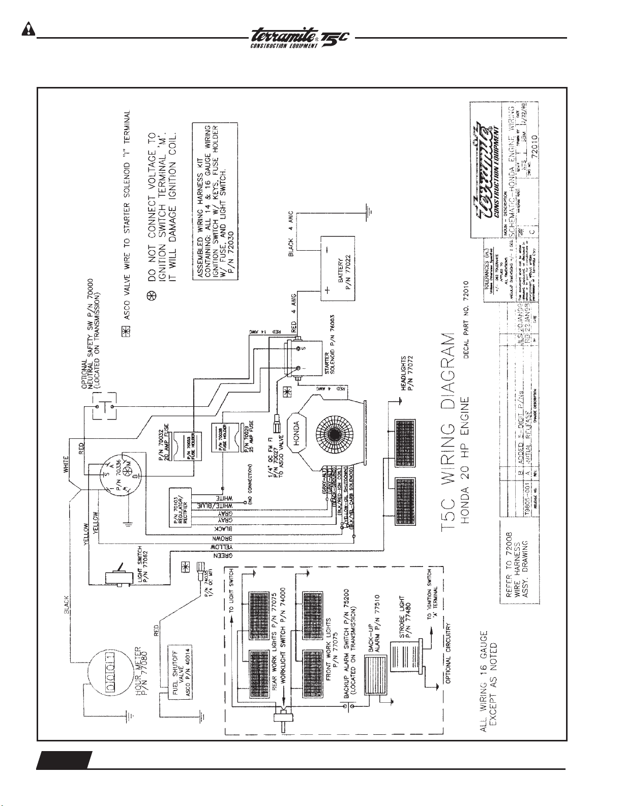
T5C Wiring Diagram Honda 20 HP
PRIOR TO 10/2000
4.4
WWW.TERRAMITE.COM/SAFETY
Charleston, WV/USA
Copyright © 2006 Terramite Corporation
(© 1993 Terramite Corp.)
1.800.428.3772
Intl. 1 .304.776.4231
Page 61

Read Operators Manual For Safety
Pre - 1997 Model T5C Wiring Diagram Honda 20 HP
PARTS MANUAL
Electrical and Wiring
1.800.428.3772
Intl. 1 .304.776.4231
WWW.TERRAMITE.COM/SAFETY
Copyright © 2006 Terramite Corporation
4.5
Charleston, WV/USA
Page 62
Read Operators Manual For Safety
Electrical and Wiring
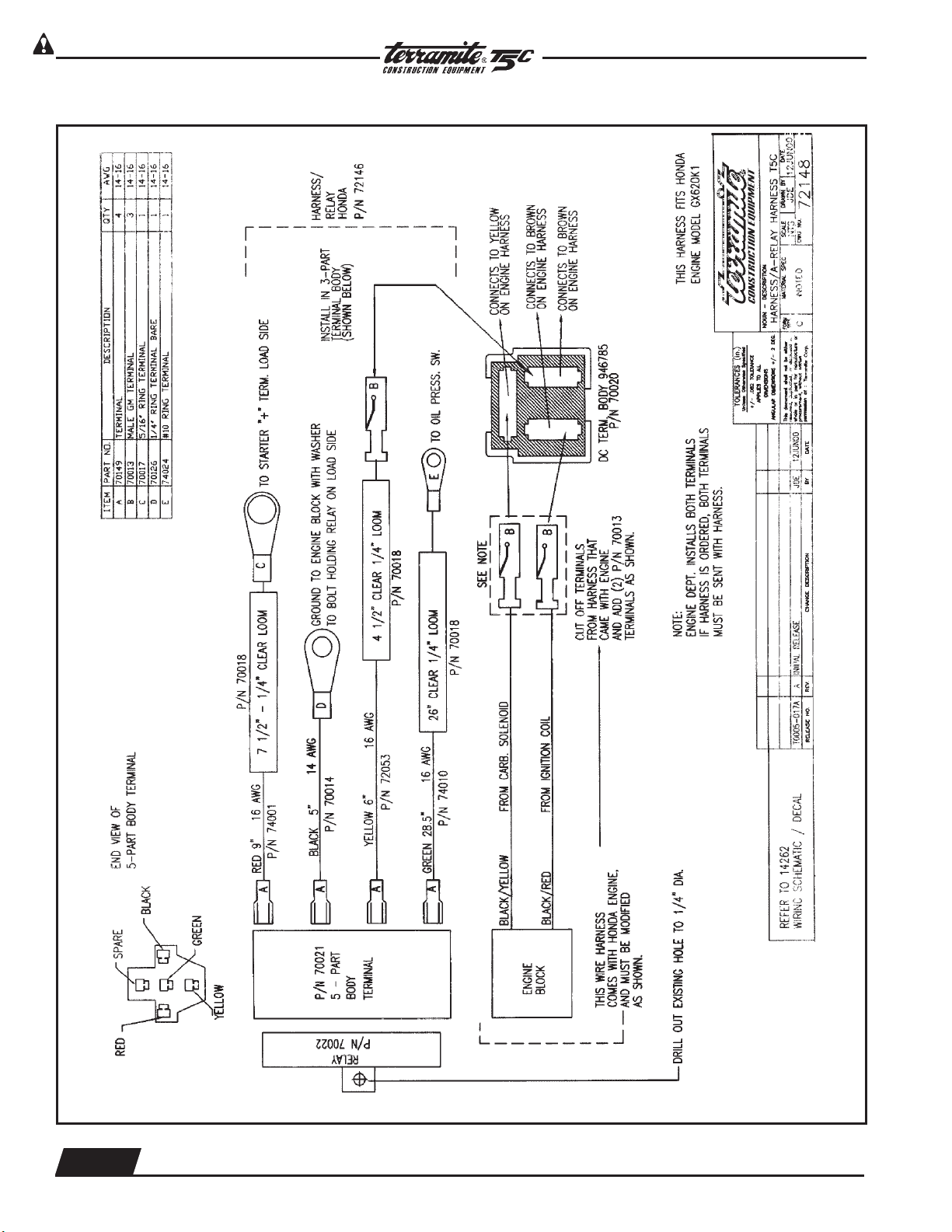
Harness/ A-Relay Harness T5C
PARTS MANUAL
4.6
WWW.TERRAMITE.COM/SAFETY
Charleston, WV/USA
Copyright © 2006 Terramite Corporation
1.800.428.3772
Intl. 1 .304.776.4231
Page 63

Read Operators Manual For Safety
Harness/ Honda Engine T5C
PARTS MANUAL
Electrical and Wiring
1.800.428.3772
Intl. 1 .304.776.4231
WWW.TERRAMITE.COM/SAFETY
Copyright © 2006 Terramite Corporation
4.7
Charleston, WV/USA
Page 64

Read Operators Manual For Safety
Electrical and Wiring
Harness/ Honda Voltage Regluator Harness/ A-Relay Harness
PARTS MANUAL
4.8
WWW.TERRAMITE.COM/SAFETY
Charleston, WV/USA
Copyright © 2006 Terramite Corporation
Harness/A-Relay Harness
1.800.428.3772
Intl. 1 .304.776.4231
Page 65

Read Operators Manual For Safety
PARTS MANUAL
Electrical and Wiring
Harness - Honda DashT5C
1.800.428.3772
Intl. 1 .304.776.4231
WWW.TERRAMITE.COM/SAFETY
Copyright © 2006 Terramite Corporation
4.9
Charleston, WV/USA
Page 66

Read Operators Manual For Safety
Electrical and Wiring
PARTS MANUAL
Terramite Suggests Keeping a Current Journal on Replacement Parts
for Quick Reference or Field Notes on Your Machine
_________________________________________________________
_________________________________________________________
_________________________________________________________
_________________________________________________________
_________________________________________________________
_________________________________________________________
_________________________________________________________
_________________________________________________________
_________________________________________________________
_________________________________________________________
_________________________________________________________
_________________________________________________________
_________________________________________________________
_________________________________________________________
_________________________________________________________
_________________________________________________________
_________________________________________________________
_________________________________________________________
_________________________________________________________
_________________________________________________________
_________________________________________________________
_________________________________________________________
_________________________________________________________
_________________________________________________________
_________________________________________________________
_________________________________________________________
_________________________________________________________
Remember to Read, Understand and Follow Your Operator's Hand-
book on Safety and the Correct Procedure for Safe Operation and
Handling of Your Compact Tractor Loader Backhoe.
4.10
WWW.TERRAMITE.COM/SAFETY
Charleston, WV/USA
Copyright © 2006 Terramite Corporation
1.800.428.3772
Intl. 1 .304.776.4231
Page 67

Read Operators Manual For Safety
PARTS MANUAL
Options
Tires
1
2
3
FRONT TIRES
4
5
6
REAR TIRES
ITEM PART NUMBER DESCRIPTION RIM INFORMATION QTY.
51274 Front Tire
1 52741 Front Tire 2
52771 Front Tire
51174 Softrac Rear Tire
2 51741 Softrac Rear Tire 2
51771 Softrac Rear Tire
51272 Std. Front Tire (prior to 3-03)
3 52721 Std. Front Tire (prior to 3-03) 2
52761 Std. Front Tire (prior to 3-03)
51173 HF Rear Tire
4 51761 HF Rear Tire 2
51731 HF Rear Tire
5 51034 Industrial Front Tire 2
6 51030 Industrial Rear Tire 2
Mounted on 4 Hole Rim (1-29.2)
used prior to 6-96
Mounted on 5 Hole Rim (1-29.6)
used after 6-96
Mounted on 15"x13" Rim (1-18.3)
used prior to 11-95
Mounted on 15"x13" Rim (1-18.5)
used after 11-95
Mounted on 4 Hole Rim (1-29.2)
used prior to 6-96
Mounted on 5 Hole Rim (1-29.6)
used after 6-96
Mounted on 15"x13" Rim (1-18.3)
used prior to 11-95
Mounted on 15"x13" Rim (1-18.5)
used after 11-95
Mounted 12" X 7" Rim (1-29.6)
used after 2-03
Mounted on 5 Hole Rim (1-29.6)
used after 2-03
PN #52871
PN #51184
PN #52871
PN #51184
PN #50021
PN #50022
1.800.428.3772
Intl. 1 .304.776.4231
WWW.TERRAMITE.COM/SAFETY
Copyright © 2006 Terramite Corporation
5.1
Charleston, WV/USA
Page 68

Read Operators Manual For Safety
Options
View of Work Lights and Canopy
1 2
Amber Reflectors
14055
Decal
14032
PARTS MANUAL
14031
Red Reflectors
ITEM PART NUMBER DESCRIPTION QTY.
1 77075 Light, Flood, Rect. 2or4
2
18007 Canopy, Fiberglass Only (resale)
18067 Canopy w/Hardware
Fits 2 post ROPS style machine
prior to 1-97 (NOT SHOWN)
1
3 77075 Work Lights, Front and Back Mount 4
4 77480 Strobe Light 1
View of Work Lights
Mounted Front and Back
4
3
Strobe Light
5.2
WWW.TERRAMITE.COM/SAFETY
Charleston, WV/USA
Copyright © 2006 Terramite Corporation
1.800.428.3772
Intl. 1 .304.776.4231
Page 69

Read Operators Manual For Safety
Clam Shell 4 in 1 Bucket
PARTS MANUAL
Options
1 2 3
4
5 6
8 9 6
7
10
6
SEE NEXT PAGE
ITEM PART NUMBER DESCRIPTION QTY.
146
6
13
1112
1 85072 Guide w/Hose 1
2 85010 Strap - Hose Guide 1
3 22025 Bolt, 1/4" x 3/4" LG 2
4 28504 Nut, 1/4" Lock 2
5 13000 Pin/w - Front Curl Cylinder (Rod) 1
6 20082 Nut, 3/8" - 16NC Flange 9
7 22174 Fitting - 1/4" Straight Male to 1/4" Female Swivel 90
°
2
8 81126 Cylinder/A, Clam Bucket 2
9 17136 Pin/w - Clam Cylinder (Rod End) 2
10 17138 Clam/w - 4 in 1 1
12 19333 Blade/w - 4 in 1 Clam 1
13 17137 Pin/w - Clam Cylinder (Barrel End) 2
14 13200 Pin/w - Bucket to Loader Arms 2
1.800.428.3772
Intl. 1 .304.776.4231
WWW.TERRAMITE.COM/SAFETY
Copyright © 2006 Terramite Corporation
5.3
Charleston, WV/USA
Page 70

Read Operators Manual For Safety
Options
View from Under Dash for Clam Shell 4 in 1 Bucket
PARTS MANUAL
(Only as Factory Installed Option)
1 1 2
3
ITEM PART NUMBER DESCRIPTION QTY.
1 84102 Hose, 1/4 " x 104" 2
2 20146 Valve, Loader, 3 Spool 1
(Used with Clam Shell
Bucket Only)
3 22784 Fitting, 1/2 "M 90° x 1/4 "M Swivel 2
5.4
WWW.TERRAMITE.COM/SAFETY
Charleston, WV/USA
Copyright © 2006 Terramite Corporation
1.800.428.3772
Intl. 1 .304.776.4231
Page 71

Read Operators Manual For Safety
View of Clam Shell 4 in 1 Bucket from Drivers Position
1 2 3 4
PARTS MANUAL
Options
5
ITEM PART NUMBER DESCRIPTION QTY.
1 84102 Hose/A - 1/4" Male Pipe Ends 102" Lg. 2
2 23174 Fitting - 1/4" Male to 45°, 1/4" Female Swivel 2
3 20174 Fitting - 1/4" Straight Male to 1/4" Female Swivel 4
4 88418 Hose/A - 1/4" Male Pipe Ends 18" Lg. 2
5 80054 Hose/A - 1/4" Male Pipe Ends 36" Lg. 2
6 21403 Handle, Loader, Black 1
(Used with Clam Shell
Bucket Only)
View of Dash for Clam Shell
4 in 1 Bucket
(Only as Factory Installed Option)
1.800.428.3772
Intl. 1 .304.776.4231
WWW.TERRAMITE.COM/SAFETY
Copyright © 2006 Terramite Corporation
6
5.5
Charleston, WV/USA
Page 72

Read Operators Manual For Safety
Options
View of Street Pads Flip Over Pad
PARTS MANUAL
1
ITEM PART NUMBER DESCRIPTION QTY.
3
1 11595 Street Pad, Detachable 2
2 11129 Flip Over Pad 2
3 17156 Pin, Pull 1" x 41/8"2
2
NOT
SHOWN
11599 Street & Cleat Pad Kit, Detachable 1
Tooth Caps
NOTE: When installing new caps
product number should be on the
inside and brand name should be
to outside.
ROL/PIN Not Shown
9
5 6
ITEM PART NUMBER DESCRIPTION QTY.
7
8
Tooth Cap Not Shown
10
5 10587 Tooth Cap Fits machines built from 2-87 to 12-89 NA
6 10500 Tooth Cap Fits machines built after 1-90 NA
7 10590 Tiger Tooth Fits machines built after 1-90 NA
8 10591 Tiger Tooth Fits machines built after 1-90 NA
9 10530 Roll/Pin NA
10 19036 Tooth Cap 65-2-87 NA
11 19114 Kit Includes Shank, Tooth and Pin
12 10510 Weld on Shank
SPECIAL 10599 Punch, for 1-05.SD & TT Tooth Caps
TOOL
5.6
WWW.TERRAMITE.COM/SAFETY
Charleston, WV/USA
Copyright © 2006 Terramite Corporation
1.800.428.3772
Intl. 1 .304.776.4231
Page 73

Read Operators Manual For Safety
Quick Attach Backhoe Buckets after May 1, 1998
PARTS MANUAL
Options
1
5
9
2 3
6
10
7
12
4
8
11
ITEM PART NUMBER DESCRIPTION QTY.
1
19133 Bucket, 8”, Quick Attach, T5C/T7
19279 Bucket, 10", Quick Attach, T5C/T7
1
2 19069 Bucket, 12”, Quick Attach, T5C/T7 1
3
11160 Bucket, 16”, Quick Attach, T5C/T7 (Standard)
19265 Bucket, 18”, Quick Attach, T5C/T7
1
4 19183 Bucket, 20”, Quick Attach, T5C/T7 1
5 19212 Bucket, 24”, Quick Attach, T5C/T7 1
6
19146 Bucket, 36”, Quick Attach, T5C/T7
19155 Bucket, 38”, Quick Attach, T5C/T7
1
7 19297 Ripper, Quick Attach, T5C/T7 1
8 11129 Outrigger Pad Assembly, Flip Over T5C/T7 2
9 19370 Blade, Landscape, Quick Attach, T5C/T7 1
10 19438 Edge, Cutting, Serrated, 56” w/Bolts, T7 1
11 19436 Edge, Cutting, Bolt-On, 56” w/Bolts, T7 1
12 19451 Bucket, Loader, Flat Bottom, 56" T7 1
1.800.428.3772
Intl. 1 .304.776.4231
WWW.TERRAMITE.COM/SAFETY
Copyright © 2006 Terramite Corporation
5.7
Charleston, WV/USA
Page 74

Read Operators Manual For Safety
Options
PARTS MANUAL
View of Auger
6
3
1
5
4
7
9 8
7
ITEM PART NUMBER DESCRIPTION QTY.
1 13499 Diggerhead, 810 "M" Series 1
2 88115 Hose, 1/2" x 115"* 2
3 13498 Bracket, Hose, Post Drill * 3
4 11165 Chain, 5/16 proof coil (by foot)* 3'
13411 Auger, 6" diameter 1
5
13404 Auger, 9" diameter 1
13403 Auger, 12" diameter 1
13407 Auger, 15" diameter 1
6 13457 Chain Hook Bracket* 2
7 13412 Tooth, Auger, Pengo, Outer 2
8 13413 Tooth, Auger, Pengo, Inner 2
9 13414 Tooth, Auger, Pengo, Point 1
NOT
SHOWN
NOT
SHOWN
5.8
85005 Installation Kit (Complete) 1
13495 Diesel Installation Kit (Complete) 1
*Included with PD5 Installation Kit
WWW.TERRAMITE.COM/SAFETY
Charleston, WV/USA
Copyright © 2006 Terramite Corporation
1.800.428.3772
Intl. 1 .304.776.4231
Page 75

Read Operators Manual For Safety
PARTS MANUAL
Options
View of Auger Connections
32 41 5
6
12
13
14
15
1011
ITEM PART NUMBER DESCRIPTION QTY.
89
7
16
1 20093 Quick Attach Fitting* 2
2 13422 Knob, Valve, Hydraulics, Auger* 1
3 25728 Fitting, 11/16" MB x 1/2" F SW 90º* 3
4 85013 Valve, Hydraulic, Auger* 1
5 21788 Fitting, 1/2" MP x 1/2" FS* 1
6 88820 Hose, 1/2" x 20"* 2
7 13406 Bracket, Valve, Hydraulic, Auger* 1
8 22704 Fitting, 3/4" pipe street ELL** 1
9 25228 Fitting, #12 "O" Ring x 1/2" FPT* 4
10 22702 Fitting, Nipple 1/2" x 3"* 2
11 21288 Fittings, 1/2" MP x 1/2" FP 90º* 3
12 88115 Hose, 1/2" x 115" 2
13 20093 Quick Attach Fitting 2
14 21288 Fittings, 1/2" MP x 1/2" FP 90º* 2
15 25054 Dust Plug-Male (shown coupled to female) 2
16 25294 Dust Cap-Female (shown coupled to male) 2
*Included with PD5 Installation Kit **Included with PD5-D Installation Kit
1.800.428.3772
Intl. 1 .304.776.4231
WWW.TERRAMITE.COM/SAFETY
Copyright © 2006 Terramite Corporation
5.9
Charleston, WV/USA
Page 76

Read Operators Manual For Safety
Options
View of Back-up Alarm and Connections
PARTS MANUAL
1
2
ITEM PART NUMBER DESCRIPTION QTY.
3 4 5 6
1 77510 Alarm, Back-up* 1
2 77101 Harness, Back-up Alarm* 1
3 77101 Harness, Back-up Alarm* 1
4 75200 Switch, Back-up Alarm* 1
5 61624 Pedal Shaft w/Bracket* 1
6 77522 Bracket, Back-up Alarm Switch* 1
NOT
SHOWN
77599 Back-up Alarm Kit 1
*Included in BK-BU.Alarm Kit
5.10
WWW.TERRAMITE.COM/SAFETY
Charleston, WV/USA
Copyright © 2006 Terramite Corporation
1.800.428.3772
Intl. 1 .304.776.4231
Page 77

Read Operators Manual For Safety
PARTS MANUAL
Translation Chart
ENGLISH FRANÇAIS DEUTSCH ESPAÑOL
adapter adaptateur Zwischenstück adaptador
arm bras Arm brazo
axle assembly essieu ensemble Achse vollst eje conjunto
axle shaft arbre d'essieu Achsenwelle barra eje
bearing palier Lager cojinete
body carrosserie Karosserie carrocería
body assembly ens carrosserie Karosserie vollst conj carrocería
bolt boulon Bolzen bulón
boom flèche Hubarm aguilón
boot capuchon Kappe capuchón
bracket support Winkel grampa
brake head assembly étrier frein ens Bremskopf vollst cabeza freno conj
brake lever assembly ens levier trein Bremsebel vollst conj planca freno
brake shoe patin frein Bremsschuh zapata freno
breather reniflard Entlüse carcasa
bucket godet Schaufel cucharón
bushing chemise Buchse buje
button bouton Knopf botón
cable câble Kabel, Seil Cable
cam came Nocke leva
cap chapeau Kappe tapa
carburetor carburateur (mélangeur) Vergaser carburador
case carter Gehäuse caja
chain chaînes Kette cadena
Channel canal, moulure U-Träger, Profil perfil
choke enrichisseur Starterklappe ahogador
circuit breaker disjoncteur Unterbrecher disyuntor
circuit circuit Stromkreis circuito
clamp attche, collier Klammer, Einspannbacke abrazadera
cleaner épurateur Luftreiniger filtro
clevis chape Gabelkopf horquilla
clip agrafa Klemme, Bügel fbroche
collar collier Bundring, Flansch collar
column montant, colonne Säule columna de dirección
cone cône, bague intériéure Konus, Kegel cónico
connecting de liaison verbinden conectar
connection connexion Verbindungsstück, conexión
connector raccord Anschluss, Stecker conector
control commande Steuerung, Betätigung control
converter convertisseur Drehmomentwandler convertidor
cotter pin goupille fendu Splint chaveta
counterweight contrepoids Gegengewicht contrapeso
coupler raccord Anschlussstück, conector, enganche
Schnellwechsler
coupling accouplement Verbindungsstück acoplamiento
cover couvercle Deckel cubierta, tapa
crankcase carter moteur Kurbelgehäuse cárter
crankshaft vilebrequin Kurbelwelle cigüeñal
crosshead traverse Kreuzkoph cruceta
cup coupelle Aussenring, Schale taza
1.800.428.3772
Intl. 1 .304.776.4231
WWW.TERRAMITE.COM/SAFETY
Copyright © 2006 Terramite Corporation
6.1
Charleston, WV/USA
Page 78

Read Operators Manual For Safety
PARTS MANUAL
Translation Chart (Continued)
ENGLISH FRANÇAIS DEUTSCH ESPAÑOL
cushion coussin Dämpfungselement, amortiguador
Sitzpolster, Vollgummi
cylinder cylindre Zylinder cilindro
cylinder block bloc-cylindres Motorblock, Zylinder- bloque de motor
block
decal décalque, décalcomanie Abziebild, Beschriftung calcomania
detachable amovible abnehmbar, geteilt separable
differential différentiel Differential diferencial
diode diode Diode diodo
dipstick jauge baïonnette Messstab varilla medidora
direction switch inverseur de marche Richtungsschalter interruptor de direccion
directional de sens de marche richtungsabhängig sentido de marcha
disc disque Scheibe disco
distributor allumeur Verteiler, Zündverteiler distribuidor
divider diviseur, répartiteur Teller, Verteiler divisor
dowel goujon Passstift, Haltestift espiga
drive axle essieu moteur Antriebsachse eje motriz
drum tambour Trommel tambor
dual jamelé, double doppelt, zweifach doble
elbow coude Kniestück, Winkelstück codo
element élément Element, Einsatz elemento
enclosure carter, carénage Umrandung, Gehäuse compartimiento
end terminal, extrémité Ende extremo
engine moteur Motor motor
exhaust échappement Auspuff escape
extension prolongement, rollonge Verläagerung extensión
exhaust valve souparpe d'échappement Auspuff-, Auslassventil válvula de escape
fan ventilateur Lüfter ventilador
felt feutre Filz anillo de retén
fender aile, pare-boue Schutzblech, Kofflügel guardabarros
film film, autocollant Aufkleber pelicula
filter filtre Filter filtro
fitting graisseur, raccord Nippel, Schraubverbindung acoplamiento
flap rabat, bavette Felgenrand, Klappe pestaña
flasher clignotant Blinkgeber contacto intermitente
flash lamp ampoule de clignotant Blinkleuchte bombilla intermitente
float flotteur gleiten, schwimmen flotador
floor sol, plancher Boden piso
flow débit, courant, flux Strömung, Durchfluss flujo
flywheel volant (moteur) Schwungscheibe volante
flow protector protecteur de débit Durchfluss-Schutzvorrichtung protector de flujo
foot pied Fuss pie
fork fourche Gabel horquilla
forward en avant vorwärts adelante, hacia adelante
frame châssis Rahmen bastidor
front avant vorne, Front frente, parte delantera
fuel carburant Kraftstoff combustible
FFTL triple levée Dreifach-Vollfreihub alto despejo libre
fuse fusible Sicherung fusible
gasket joint Dichtung junta
6.2
WWW.TERRAMITE.COM/SAFETY
Charleston, WV/USA
Copyright © 2006 Terramite Corporation
1.800.428.3772
Intl. 1 .304.776.4231
Page 79

Read Operators Manual For Safety
PARTS MANUAL
Translation Chart (Continued)
ENGLISH FRANÇAIS DEUTSCH ESPAÑOL
guage jauge Anzeiger medidor, indicador,
calibrador
gear pignon, engrenage Zahnrad, Gang engranaje
glow plug bougie de préchauffage Glühkerze bujía incandescente
grommet virole Tülle, Dichtungsring arandela aislante
group ensemble Gruppe, Satz grupo
guard protecteur Schutz, Abdeckung protector
guide guide Führung guía
hand brake frein à main Handbremse freno de emergencia
handle poignée Griff, Handgriff asa
harness faisceau Kabelbaum, Verdrahtung mazo de cables
head téte Kopf culata
head lamp phare AV Scheinwerfer luz delantera
height hauteur Höhe altura
hinge charnière Gelenk, Scharnier bisagra
hold down tendeur Aufspannvorrichtung sujetador
holder support Halter soporte
hood capot Motorhaube capó
hook crochet Zughaken gancho
horn avertisseur Hupe, Signalhorn bocina
hose durite, flexible Schlauch manguera
housing boîtier, carter Gehäuse caja
hub moyeu Nabe, Radnabe maza
hydraulic hydraulique Hydraulik hidráulico
ignition allumage Zündung encendido
indicator indicateur Anzeigevorrichtung indicador
injection injection Einspritzung inyección
injector injecteur Einspritzventil inyector
inner intérieur innen interior
insert pièce rapportée Einsatz inserto
instrument instrument Instrument instrumento
insulation isolation Isolierung aislante
insulator isolateur Isolator, Nichtleiter aislador
intake valve soupape d'admission Ansaugventil válvula de admisión,
válvula de aapiración
interface surface de réparation, Übertragungseinheit entrecara, zona Interfacial
interface
jacket chemise, jupe Mantel, Wärmeisolierung camisa, chaqueta
intermediate intermédiaire, moyen indirekt intermedio, medianero
joint joint Gelenk, Verbindung junta, unión, juntaura
keeper détente Gegenmutter, Halter tirante, fijader, retentór
key clé, clavette Schlüssel, Keil llave
lever levier Hebel palanca
leveler niveleur, correcteur Planierer nivelador
light lumière Leuchte luz
line canalisation Leitung tuberia
liner chemise, garniture Laufbuchse camisa
lining revêtement, garniture (frein) Auskleidung, Belag revestimiento, forro
link baillette, maillon Glied, Gelenkstück eslabón
locknut contre-écrou Kontermutter, Siche- tuerca de traba
rungsmutter
1.800.428.3772
Intl. 1 .304.776.4231
WWW.TERRAMITE.COM/SAFETY
Copyright © 2006 Terramite Corporation
6.3
Charleston, WV/USA
Page 80

Read Operators Manual For Safety
PARTS MANUAL
Translation Chart (Continued
ENGLISH FRANÇAIS DEUTSCH ESPAÑOL
lockwasher rondelle d'arrêt Federring arandela de seguridad
magnet aimant Magnet imán
manifold collecteur Krümmer múltiple
master cylinder maître-cylindre Hauptzylinder cilindro maestro
maximum maximum maximal máximo
meter instrument, mètre Messgerät medidor, dosificador
modulating de modulation Modulation modulador
motor moteur Motor, elektr. motor
mount support anbauen, montieren montar
mounting montage Befestigung, Anbausatz montaje
muffler silencieux d'échappement Schaildämpfer silenciador
nipple graisseur Schmiernippel boquilla
nut écrou Mutter tuerca
oil huile Öl aceite
oil level niveau d'huile Ölstand nivel del aceite
outer extérieur aussen exterior
oil filter filtre à huile Ölfilter filtro de aceite
O-ring joint torique O-Ring sello anular
oversize surdimensionné, majoré Übermass, Übergrösse sobremedida
packing gerniture d'étanchéité Abdichtung empaquetadura
pad tampon, coussin Polster, Unterlagsblock almohadilla
pan carter, cuvette Ölwanne colector del cárter
panel tableau Verkleidungsblech, panel, tablero de
Instrumentenbrett instrumentos
pedal pédale Pedal pedal
pin goupille, axe Bolzen, Stift pasador
pinion pignon Ritzel piñón
piston piston Kolben pistón
pivot pivot Anlenk-, Drehpunkt, Auf- pivote
hängung
plate plaque, plateau Platte, Blech placa, plancha
plug bouchon Schraubstopfen tapón, bujia
plunger plongeur Tauch-, Ventilkolben émbolo
polished poli poliert pulido
precleaner préfiltre Vorreiniger antefiltro
primary primarire Haupt-, Vor-, primär primario
priority priorité, séquence Sicherheits-, Vorrang prioridad
protector protecteur Schutzvorrichtung protector
pulley pulie Riemenscheibe polea
pump pompe Pumpe bomba
push rod poussoir Schubstange varilla de empuje
race chemin de roulement, Lager-, Laufring anillo de cojinete
cuvette
radiator radiateur Kühlernetz radiador
rail rail (glissiére) Schiene riel, mástil
rear arrière, AR rückwärts, hinten posterior, trasero
rectifier redresseur Gleichrichter rectificador
regulator régulateur Regler, Reguliervorrichtung regulador
relay relais Relais relé
relief valve soupape de décharge Überdruckventil válvula de alivio
6.4
WWW.TERRAMITE.COM/SAFETY
Charleston, WV/USA
Copyright © 2006 Terramite Corporation
1.800.428.3772
Intl. 1 .304.776.4231
Page 81

Read Operators Manual For Safety
PARTS MANUAL
Translation Chart (Continued)
ENGLISH FRANÇAIS DEUTSCH ESPAÑOL
repair réparation Reparatur reparación
required (Reqd.) requis erforderlich requerido
reservoir réservoir Tank depósito, tanque
retainer arrètoir Halterung retén
reverse marche AR Rückwärsgang marcha atrás, reverso
right hand (RH) côté droit, à droit rechts lado derecho (L.D.)
ring anneau, joint Ring anillo, aro, argolla
rivet rivet Niete remache
rocker arm culbuteur Kipphebel balancin
rod bielle Stange, Pleuelstange varilla
roller galet Laufrolle rodillo
rotor rotor Rotor, Laufrad rotador, rotor, rodete
seal joint Dichtring sello
seal-o-ring joint torique O-Ring-Dichtung anillo,
anillo de estancamiento
sealant produit d'étanchéité Dichtungsmittel sellante, sellador
seal-u-cup joint en demi-lune U-Profil-Dichttungsring copa en "U"
seat siège Sitz asiento
secondary secondaire Anbau-, Hilfs-, Sekundär secundario, auxiliar
sender emetteur, sonde Geber (Kraftstoffstand) sensor
sending unit émetteur Messwertgeber unidad sensora
separator séparateur Separator, Abscheider separador
setscrew vis de fixation Gewindestift tornillo de traba, tornillo
prisionero
shaft arbre, axe Welle eje, mango largo, rastágo
shield bouclier, écran de pro- Abdeckung, Schild protector
tection
shim cale de réglage Beilagscheibe calce
short block bloc-moteur nu Teil-, Skelettmotor bloque de motor sin ac-
cesoriso, bloque parcial
shroud panneau, plaque Abdeckplatte cubierta, refuerzo de
ventilador
sideshift déport latéral Seitenschubvorrichtung desplazador lateral
sleeve manchon, chemise Büchse, Hülse manguito
snap jonc d'arrêt Sprengring anillo de presión,
cierre de resorte
socket douille, chape Fassung enchufe
solenoid solénoïde Magnetspule solendoide
spacer entretoise Distanzstück espaciador
spark plug bougie d'allumage Zündkerze bujía
spider croisilon Gelenkkreuz cruceta
spindle pivot, fusée, broche Spindel, Achszapfen punta de eje
spool tiroir Ventilstössel carrete
springs ressort Feder resortes
sprocket barbotin Antriebsrad rueda dentada
standard (Std.) normal Standard estándar
starter démarreur Anlasser arranque
stationary (Stat.) stationnaire Aussenmast, stationär estacionario, inmóvil
stator stator Ständer, Stator estator
steering directon Lenkung directción
1.800.428.3772
Intl. 1 .304.776.4231
WWW.TERRAMITE.COM/SAFETY
Copyright © 2006 Terramite Corporation
6.5
Charleston, WV/USA
Page 82

Read Operators Manual For Safety
PARTS MANUAL
Translation Chart (Continued)
ENGLISH FRANÇAIS DEUTSCH ESPAÑOL
stem tige Schaft vóstago
strainer filtre, crépine Sieb filtro
strap sangle Riemen, Gurt banda, correa
strut étai, tirant Strebe tirante de dirección
stud goujon, tenon Stehbolzen espárrago
support support Auflager, Abstützung soporte
switch interrupteur Schalter interruptor
tag étiquette Anhänger etiqueta
tapered conique konisch, kegelförmig, perfil cónico, aguzado
verjüngt
tappet poussoir Anschlag, Stössel levantaválvulas
tee té T-Stück conexión "T"
terminal borne Anschlussklemme terminal
thermistor thermistor Thermistor, Temperatur- termistor
fühler
thermostat thermostat Thermostat termostato
tightner tendeur Spanner tensor, adjustador
tilt cylinder vérin d'inclinaison Neigezylinder cilindro de inclinación
tire pneumatique Reifen neumático
transfer déclacomanie, autocollant Abziehbild transferencia
transmission transmission, boîte de vi- Getriebe transmisión
tesses
tread-step marchepied Triffstufe estribo antirresbalante
tube tuyau, tube, gicleur Rohr, Schlauch tubo
tubing canalisations Rohr, Schlauchleitung tuberias, tubos
undersize sous-dimensionne, minore Untermass bajomedida
union raccord Anschiussstück, Verbinaung unión
universal joint cardan Kreuzgelenk junta universal
upright montant senkrecht, Hubgerüst montante vertical
valve soupape, clapet Ventil válvula
valve mechanism culbuterie Ventilsteuerung mecanismo de válvulas
vacuum vide, dépression Vakuum, Unterdruck vacio, vacuómetro
washer rondelle Unterlegscheibe aradela
water eau Wasser agua
water pump pompe à eau Wasserpumpe bomba de agua
wear strip bande d'usure Verschleissstreifen plancha de desgaste
wheel roue Rad rueda
wheel cylinder cylindre de roue Radbremszylinder cilindro de rueda
wiper racleur Wischer, Abstreifer limpiaparabrisas
wire fil Draht, Leitung alambre, cable
wire harness faisceau de fils Kabelbaum mazo de cables
wire marker marquer de fil Kabelmarkierung marcador de alambre
worm vis sans fin Schnecke tornillo sin fin
wrap revêtement, enveloppe Hülle envolver, envoltura
yoke chape Gabelgelenk, Joch horquilla
6.6
WWW.TERRAMITE.COM/SAFETY
Charleston, WV/USA
Copyright © 2006 Terramite Corporation
1.800.428.3772
Intl. 1 .304.776.4231
Page 83

Read Operators Manual For Safety
A
Adapter Assembly with Power Steering ........................... 2.11
Adapter Assembly without Power Steering ..................... 2.11
Alarm, Back-up ................................................................. 5.10
Alignment Pin (Needle Brg.) (9) ........................................ 3.23
Arm Cylinder ............................................................. 3.3, 3.22
ASCO Fuel Shutoff Valve ................................................. 3.11
ASCO Fuel Shutoff Valve Assembly ................................ 3.11
Auger, 12" diameter............................................................ 5.8
Auger, 15" diameter............................................................ 5.8
Auger, 6" diameter ............................................................. 5.8
Auger, 9" diameter ............................................................. 5.8
Auxillary P.T.O. Kit ............................................................. 2.7
Axle Pin ............................................................................... 3.3
Axle Pin, 11/4" .................................................................... 3.3
Axle Weldment ................................................................... 3.3
B
48" Loader Bucket ............................................................. 3.3
56" Loader Bucket .............................................................. 3.3
Back-up Alarm Kit ............................................................. 5.10
Back Up Washer ............................................................... 2.11
Backplate Assembly .......................................................... 2.8
Backplate Assy., Cessna, without Power Steering ........... 2.11
Backplate Assy., Eaton, with Power Steering ................... 2.11
Backplate Assy., w/valve plate, Eaton .............................. 2.11
Baffle-Pinion Bearing ........................................................ 3.20
Ball 9/32 inch (22mm) ........................................................ 3.23
Ball .................................................................................... 2.11
Ball-7/32 inch (6mm) dia. ................................................... 3.23
Battery ....................................................................... 3.9, 3.11
Bearing Assembly ............................................................. 3.21
Bearing Block ......................................................................2.9
Bearing Race ..................................................................... 2.11
Bearing Seal ...................................................................... 3.12
Bearing .............................................................................. 2.11
Bearing, Inner After 6-96................................................. 3.12
Bearing, Inner Before 6-96 .............................................. 3.12
Bearing, Outer After 6-96 ................................................ 3.12
Bearing, Outer Before 6-96 .............................................. 3.12
Bearing, Thrust ......................................................... 3.3, 2.11
Blade/w - 4 in 1 Clam .......................................................... 5.3
Blade, Landscape, Quick Attach ........................................ 5.7
Bolt ................................................................................... 3.14
Bolt, 1/2" x 11/4" ................................................................. 3.5
Bolt-Break Mounting ........................................................ 3.21
Bolt-Carrier Cover ............................................................. 3.21
Bolt-Differential Bearing Cap ............................................ 3.21
Bolt-Drive Gear ................................................................. 3.21
Bolt-Parking Brake Assembly ........................................... 3.16
Bolt, 1/4" x 3/4" LG ............................................................. 5.3
Bolt-Wheel ....................................................................... 3.21
PARTS MANUAL
INDEX
Boom Assembly ................................................................ 3.19
Boom Bushings ................................................................ 3.19
Boom Cylinder .................................................................. 3.19
Bracket, Battery ................................................................ 3.11
Bracket, Hose, Post Drill .................................................... 5.8
Brake Band ....................................................................... 3.14
Brake Cable ....................................................................... 3.14
Brake Drum ....................................................................... 3.16
Brake Lever, Adjustable ...................................................... 3.5
Brake Off Set Link ............................................................. 3.14
Bucket, 10", Quick Attach .................................................. 5.7
Bucket, 12", Quick Attach .................................................. 5.7
Bucket, 16", Quick Attach .................................................. 5.7
Bucket, 18", Quick Attach .................................................. 5.7
Bucket, 20", Quick Attach .................................................. 5.7
Bucket, 24", Quick Attach .................................................. 5.7
Bucket, 36", Quick Attach .................................................. 5.7
Bucket, 38", Quick Attach .................................................. 5.7
Bucket, 8", Quick Attach .................................................... 5.7
Bucket, Loader, Flat Bottom, 56" ........................................ 5.7
Bucket, 16”, Standard ....................................................... 3.17
Bucket, 48" and 56" Loader ................................................ 2.5
Bumper ................................................................................ 3.3
Bushing .................................................................... 3.14, 3.19
Bushing Spindle ................................................................. 3.3
C
Cable, Battery to Ground 7" ............................................. 3.11
Cable, Battery to Solenoid 48" .................................. 3.9, 3.11
Camplate, For Cessna Trans. ............................................ 2.11
Camplate, For Eaton Trans. .............................................. 2.11
Canopy, Fiberglass Only (resale) ....................................... 5.2
Canopy w/Hardware .......................................................... 5.2
Cap Screw .................................................................. 2.11, 2.8
Cap, Hyd. Breather Filter w/Dipstick .................................. 3.5
Cap, Steering Wheel ........................................................... 3.5
Cap-Differential Bearing ................................................... 3.21
Case-Differential ............................................................... 3.21
Castle Nut ........................................................................... 3.3
Center Assembly, Quick Attach ....................................... 3.17
Chain, 5/16 proof coil ......................................................... 5.8
Chain Hook Bracket ........................................................... 5.8
Check Valve Assembly ..................................................... 2.11
Choke Cable ...................................................................... 3.11
Clam/w - 4 in 1 .................................................................... 5.3
Clamp, Fuel Hose ................................................................ 3.7
Clip-Differential Clutch Retainer ....................................... 3.21
Commutator Cover ............................................................ 2.15
Commutator Ring .............................................................. 2.15
Commutator ...................................................................... 2.15
Companion Flange Assembly........................................... 3.21
Cotter Pin ............................................ 3.1, 3.9, 3.11, 3.12, 3.19
Coupler ............................................................................. 2.11
Coupling Shaft ....................................................................3.7
1.800.428.3772
Intl. 1 .304.776.4231
WWW.TERRAMITE.COM/SAFETY
Copyright © 2006 Terramite Corporation
7.1
Charleston, WV/USA
Page 84

Read Operators Manual For Safety
PARTS MANUAL
INDEX
Cover Plate ....................................................................... 2.11
Cover-Carrier .................................................................... 3.21
Crowd Cylinder ................................................................. 3.19
Cutting Edge (Weld On) ..................................................... 2.3
Cylinder/A, Clam Bucket .................................................... 5.3
Cylinder Assembly, Swing W/Tee Fitting ......................... 3.19
(Continued)
D
Decal Plate, Since 1965 .................................................... .3.25
Decal Plate, Warning, Serial Number, etc .......................... 3.25
Decal Plate, Warning, SN., etc. ......................................... 3.25
Decal, American Flag ........................................................ 3.24
Decal, Danger, Crush Hazard ................................... 3.24, 3.26
Decal, Diesel Only ............................................................ 3.25
Decal, Digging Depth 8’4" ............................................... 3.24
Decal, Gas Only ................................................................ 3.25
Decal, Instrument Panel .................................................... 3.25
Decal, Large Terramite ...................................................... 3.24
Decal, Maintenance .......................................................... 3.26
Decal, Notice Starting Procedure ...................................... 3.25
Decal, Parking Brake ......................................................... 3.25
Decal, Plate ROPS T5&T6 Series ...................................... 3.24
Decal, Plate, Since 1965 ..................................................... 3.25
Decal, Read Owners Manual ............................................ 3.26
Decal, Small Terramite ....................................................... 3.24
Decal, Stand Clear ............................................................. 3.24
Decal, T5C ........................................................................ 3.24
Decal, Warning Call Before You Dig ................................. 3.25
Decal, West Virginia .......................................................... 3.24
Decal, Wobblestick & Operator Hazard ............................ 3.26
Deck Center ........................................................................ 3.5
Diesel Installation Kit ......................................................... 5.8
Diggerhead, 810 "M" Series ............................................... 5.8
Dipstick Assembly ............................................................ 3.17
Dipstick for Linkage Type Only ........................................ 3.17
Dipstick T5 and T5B Older Style ........................................ 3.5
Disc-Differential ................................................................3.21
Distributor Block ................................................................ 2.2
Drive Gear Assembly .......................................................... 2.8
Drive Motor Flange ................................................. 3.14, 3.16
Drive Motor ...................................................................... 3.14
Drive Shaft Coupler ............................................................ 3.7
Drive Shaft Coupling ........................................................ 3.27
Drive Shaft ........................................................................ 2.11
Drive Shaft Splined L3 Tooth ............................................. 3.7
Drive Shaft Assy., Splined ..................................................3.7
Dust Cap-Female ................................................................ 2.7
Dust Plug-Male .................................................................. 2.7
Dust Cap .................................................................. 3.12, 3.13
F
1/4" Fuel Filter .................................................................... 3.7
4-Way, 3-Position Valve Section ....................................... 2.20
5/16" Fuel Filter ...................................................................3.7
Face Seal ........................................................................... 2.16
Filter Base ........................................................................... 2.4
Filter, Hydraulic................................................................... 3.5
Filter, Strainer (Inside Tank) ................................................ 2.4
Filter, Strainer ...................................................................... 2.4
Fitting - 1/4" Male to 45°, 1/4" Female Swivel .................... 5.5
Fitting - 1/4" Straight Male to 1/4" Female Swivel ............. 5.5
Fitting, 1/2 "M 90° x 1/4 "M Swivel .................................... 5.4
Fitting, #10 x 1/2" x 90° ....................................................... 2.6
Fitting, #12 x 1/2" x 90°, Trans. ........................................... 2.4
Fitting, #12 x 8" adaptor ..................................................... 2.6
Fitting, #8 x 1/2" x 45° ......................................................... 2.6
Fitting, #8 x 6" adaptor ....................................................... 2.6
Fitting, 1/2" x 1/4" x 90°, Loader Valve ...................... 3.9, 3.11
Fitting, 1/2" x 90°, Loader Valve ................................. 3.9, 3.11
Fitting, 1/2" x 3/8", Trans. ................................................... 2.4
Fitting, 1/4" (front hose set) ............................................... 2.2
Fitting, 1/4" Tee (front hose set) ........................................ 2.2
Fitting, 1/4" x 45° (front hose set) .......................................2.2
Fitting, 1/4" x 45° ................................................................ 2.2
Fitting, 1/4" x 90° (front hose set) .......................................2.2
Fitting, 1/4" ....................................................................... 3.19
Fitting, 1/4", Hydraulic Hose ..............................................2.8
Fitting, 11/16" x 3/4", Trans. ............................................... 2.4
Fitting, 3/4" x 1/4" x 45° ...................................................... 2.6
Fitting, Bottom Type 1/4" ................................................... 2.4
Fitting, Fuel Tank ................................................................ 3.5
Fitting, Restrictor ................................................................ 2.6
Fitting, Straight 1/4" Swivel ................................................2.2
Fitting,Grease ............................................................. 3.9, 3.11
Fittings, 1/2" x 90° .............................................................. 2.3
Flip Over Pad ...................................................................... 5.6
Foot Pedal Control ............................................................. .3.5
Foot Pedal ........................................................................... 3.5
Front Curl Cylinder ............................................................. 3.3
Front Curl Rod .................................................................... 3.3
Front Tire ............................................................................ 5.1
Front Tube ........................................................................ 3.13
Fuel Cap, Safety ..................................................................3.3
Fuel Hose 1/4" .................................................................... 3.7
Fuel Hose 5/16" .................................................................. 3.7
New Fitting, 1/4" ................................................................. 2.2
E
Edge, Cutting, Bolt-On, 56" w/Bolts ................................... 5.7
Edge, Cutting, Serrated, 56" w/Bolts ................................. .5.7
End Yoke Assembly .......................................................... 3.20
7.2
WWW.TERRAMITE.COM/SAFETY
Charleston, WV/USA
Copyright © 2006 Terramite Corporation
G
Gasket, Relief Body ........................................................... 2.11
Gasket-Carrier Cover ......................................................... 3.21
Gear & Pinion Ass’y-Drive ............................................... 3.20
Gear Pump Part # 66034 .......................................................2.8
1.800.428.3772
Intl. 1 .304.776.4231
Page 85

Read Operators Manual For Safety
PARTS MANUAL
INDEX
Gear Pump ........................................................................... 2.8
Gear-Differential ................................................................ 3.21
Grill Assembly ..................................................................... 3.3
Guide w/Hose ..................................................................... 5.3
Guide, Spring .................................................................... 2.11
Housing, Gasket ............................................................... 2.11
H
1/4" Fuel Hose .................................................................... 3.7
5/16" Fuel Hose .................................................................. 3.7
Clamp, Fuel Hose ................................................................ 3.7
Clamp, Hose ........................................................................3.7
Handle ................................................................................. 3.1
Handle Assembly ................................................................3.1
Handle, Loader Wobblestick ............................................ 3.11
Handle, Loader, Black.......................................................... 5.5
Handle, Wobblestick, Left Rear .......................................... 2.6
Handle, Wobblestick, Right Rear ........................................ 2.6
Headlamp Assembly ........................................................... 3.5
Headlight Switch/Toggle .................................................... 3.5
HF Rear Tire ........................................................................5.1
Holder, Fuse, 20 AMP, ATO .............................................. 3.11
Hood Assembly w/Decals .................................................. 3.4
Hood, Hinge, Bushing ........................................................ 3.5
Hood Prop Bolt ...................................................................3.7
Honda 20 HP, Wiring Diagram ............ 4.4, 4.5, 4.6, 4.7, 4.8, 4.9
Hose, 1/2" x 115" .............................................................. 2.14
Hose, 1/2" x 20 ................................................................... 2.4
Hose, 1/4 " x 104" ............................................................... 5.4
Hose/A - 1/4" Male Pipe Ends 102" Lg. ............................. 5.5
Hose/A - 1/4" Male Pipe Ends 18" Lg. ............................... 5.5
Hose/A - 1/4" Male Pipe Ends 36" Lg. ............................... 5.5
Hose 1/2" x 57" (back valve section) ................................ 2.14
Hose, 1/2" x 35", Loader Valve .................................. 3.9, 3.11
Hose, 1/2" x 36"(back valve section) ................................ 2.12
Hose, 1/2" x 78"(back valve section) ................................ 2.14
Hose, 1/2" x 20", Trans. ...................................................... 2.4
Hose, 1/4" Swing Crossover, 15"............................. 2.14, 3.19
Hose, 1/4" Swing to Valve, 20" ................................ 2.14, 3.19
Hose, 1/4" Swing to Valve, 25" ................................ 2.14, 3.19
Hose, 1/4" x 131" ..................................................... 2.14, 3.19
Hose, 1/4" x 18" (front hose set) ...................................... 2.13
Hose, 1/4" x 34" (front hose set) ...................................... 2.13
Hose, 1/4" x 34", Arm Cylinder ......................................... 2.13
Hose, 1/4" x 36", Power Steering ...................................... 2.12
Hose, 1/4" x 62" (front hose set) ...................................... 2.13
Hose, 1/4" x 62", Loader Valve .................................. 3.9, 3.11
Hose, 1/4" x 63" (front hose set) ...................................... 2.13
Hose, 1/4" x 63", Loader Valve .................................. 3.9, 3.11
Hose, 1/4" x 66" (front hose set) ... ................................... 2.13
Hose, 1/4" x 66" ................................................................ 3.19
Hose, 1/4" x 66", Loader Valve .................................. 3.9, 3.11
Hose, 1/4" x 83" (front hose set) ...................................... 2.13
Hose, 1/4" x 83", Loader Valve .................................. 3.9, 3.11
Hose, 1/4" x 92" ................................................................ 3.19
Hose, 3/4" x 12"(back valve section) ................................ 2.12
Hose, 3/4" x 12", Trans. ...................................................... 2.4
Hose, 3/8" x 20"(back valve section) ................................ 2.12
Hourmeter (view from back) ............................................. 3.11
Hourmeter .................................................................... 3.4, 3.5
Housing Assembly ........................................................... 2.11
Housing ............................................................................ 2.11
Housing, Gasket ................................................................. 3.3
Housing-Axle .................................................................... 3.20
Hub, 5 on 4 after 6-1-96 ..................................................... 3.12
Hub, previous to 6-1-96 .................................................... 3.12
Hydraulic Main Power Circuit .......................................... 2.12
Hydraulic Tank .......................................................... 2.12, 3.5
Hydrostatic Transmission ....................................... 2.10, 2.11
I
Idler Gear Assembly ............................................................ 2.8
Ignition Switch w/Key ........................................................ 3.5
Inner Race ......................................................................... 2.11
Input Shaft/Wheel Tube ................................................... 3.21
Installation Kit ................................................................... 5.8
Insulator, Black ................................................................. 3.11
Insulator, Red ..............................................................3.9, 3.11
K
Key ................................................................................... 3.16
Keyway ............................................................................. 2.11
Kit-Differential Bearing ..................................................... 3.21
Kit-Inner Pinion Bearing ................................................... 3.20
Kit-Outer Pinion Bearing .................................................. 3.20
Knob .. ................................................................................ 2.6
Knob, Valve, Hydraulics, Auger ......................................... 5.9
Kohler Comm. 20/ 25 HP -Wiring Diagram ................... 4.2, 4.3
Kohler 20 HP Engine Muffler ..............................................3.7
L
L Link .. ... ..... ...................................................................... 3.11
Light, Flood, Rect. .............................................................. 5.2
Linkage Assembly, Center................................................ 3.17
Linkage Link, Left ............................................................. 3.17
Linkage Link, Right .......................................................... 3.17
Linkage .............................................................. 3.9, 3.11, 3.17
Linkage Valve Kit ....................................................... 3.9, 3.11
Load Check Plug Assembly .............................................. 2.21
Loader Arm Assembly (resale) ........................................... 3.3
Loader Circuit ................................................................... 2.13
Loader Circuit Relief Valve ............................................... 2.21
Loader Valve ..................................................................... 2.19
Loader Valve Hoses and Fittings ........................................ 2.3
Lock-Differential Shaft ...................................................... 3.21
1.800.428.3772
Intl. 1 .304.776.4231
WWW.TERRAMITE.COM/SAFETY
Copyright © 2006 Terramite Corporation
7.3
Charleston, WV/USA
Page 86

Read Operators Manual For Safety
PARTS MANUAL
INDEX
(Continued)
M
MAB/MAE Torquemotor Exploded Assey View - Typic... 2.15
Magnalloy Style Coupling .................................................3.27
Main Relief Rear Valve ........................................................ 2.5
Manifold ............................................................................ 2.15
Manual Box ......................................................................... 3.1
Metric Fasteners ................................................................ 3.23
Model J-HP High Pressure Relief ...................................... 2.11
Molded O-Ring .................................................................. 2.11
N
Nut, 3/8" - 16NC Flange ..................................................... 3.3
Nut, 3/8” NC Flange Z ...................................................... 3.19
Nut ............................................................................ 3.12, 3.14
Nut, 1/2" NC Lock ..............................................................3.19
Nut, 1/2" NF Jam ................................................................. 3.3
Nut, 3/8" NC ...................................................................... 3.13
Nut, 3/8" NC Flange Z ....................................................... 3.11
Nut, 3/8" 24" NF Lug ......................................................... 3.11
Nut, 5/8" NF Jam ................................................................. 3.3
Nut, 5/16" NF Jam ....................................................... 3.9, 3.11
Nut, 1" NFZ Jam ................................................................. 3.1
Nut, Brake Mounting ......................................................... 3.21
Nut, Acorn Cap ..................................................................2.11
Nut, Headlamp .................................................................... 3.5
Nut, Jam, Adjusting Screw ................................................ 2.11
Nut, Lug ............................................................................. 3.13
Nut-Parking Brake Assembly............................................. 3.16
Nut-Pinion ......................................................................... 3.21
O
Oil Change and Type Specifications .................................. 2.1
O-Ring 1/16" x 3" ................................................................ 2.8
O-Ring 33/32" x 7/8" ID, Back Plate .................................. 2.11
O-Ring, 1/16" x 3/8" .......................................................... 2.11
O-Ring, 1/16" x 31/4" ........................................................ 2.11
O-Ring, 3/32" x 15/16", Outer Pintle .................................. 2.11
O-Ring, 33/32" x 41/64" ..................................................... 2.11
O-Ring, 33/32" x 7/8" ........................................................ 2.11
O-Ring, Adjusting Screw .................................................. 2.11
O-Ring, Molded ................................................................ 2.11
O-Ring, Outer Pintle .......................................................... 2.11
O-Ring, Valve Seat ............................................................ 2.11
Outrigger,Guard ....................................................... 3.18, 3.19
Outrigger T5C, Handle ........................................................ 2.5
Outrigger Assembly 4 Lug ....................................... 3.18, 3.19
Outrigger Assembly 5 Lug ....................................... 3.18, 3.19
Outrigger Assembly before 3-3-99 ........................... 3.18, 3.19
Outrigger Cylinder after 3-3-99 ................................ 3.18, 3.19
Outrigger Guard ................................................................ 3.19
Outrigger Guard with pin ......................................... 3.18, 3.19
P
P.T.O. Depress Lever .......................................................... 2.7
Pedal Block ......................................................................... 3.5
Pedal Shaft .......................................................................... 3.5
Pedal Spring ........................................................................3.5
Pedal Stop Bolt ................................................................... 3.5
Pillow Block Bearing ........................................................... 3.5
Pin, 6 1/2”, Rear Curl Cylinder to Quick Attach ................ 3.17
Pin, 7 5/8”, Dipstick to Linkage ........................................ 3.17
Pin, 8 1/2”, Quick Attach Pull ........................................... 3.17
Pin, 8 1/4”, Quick Attach Bucket ...................................... 3.17
Pin/w - Bucket to Loader Arms .......................................... 5.3
Pin/w - Clam Cylinder (Barrel End) ..................................... 5.3
Pin/w - Clam Cylinder (Rod End) ........................................ 5.3
Pin/w - Front Curl Cylinder (Rod) ....................................... 5.3
Pin 1" x 6 7/8",Loader Arm .................................................. 3.3
Pin, 1" x 4" .......................................................................... 3.3
Pin, 1" x 41/8" ......................................................................3.3
Pin, 1" x 43/4" Loader Bucket ............................................. 3.3
Pin, 1" x 51/4", Arm Cylinder .............................................. 3.3
Pin, 1" x 51/4", Front Curl Cylinder ..................................... 3.3
Pin, 1" x 51/4", Front Curl Cylinder .................................... .3.3
Pin, 1" x 61/4" .................................................................... 3.19
Pin, 1" x 67/8" .................................................................... 3.19
Pin, 1" x 67/8", Loader Arm ................................................. 3.3
Pin, 1" x 73/4" .................................................................... 3.19
Pin, 1" x 77/8", Arm Cylinder Rod ....................................... 3.3
Pin, 11/4" x 71/2" ............................................................... 3.17
Pin, 11/4" x 71/4" ............................................................... 3.19
Pin, 11/4"x 81/4" ................................................................ 3.17
Pin, Main Swing ................................................................ 3.19
Pin, Tooth after 1-90 .......................................................... 3.17
Pinion - Differential ........................................................... 3.21
Plastic Disc ......................................................................... 3.1
Plate - Differential ............................................................. 3.21
Plug Cover ........................................................................ 3.21
Port Relief 2000# ................................................................. 2.5
Port Relief 2600# ................................................................. 2.5
Power Steering Gear ............................................................3.5
Q
Q.A. Plug ............................................................................ 2.7
Quick Attach Backhoe Buckets .......................................... 5.7
Quick Attach Fitting ........................................................... 2.7
R
Race, Inner After 6-96 ..................................................... 3.12
Race, Outer & Inner Before 6-96 ..................................... 3.12
Rear Axle ........................................................................... 3.16
Rear Axle - Parking Brake Assembly ................................. 3.16
Rear Bucket ....................................................................... 3.19
7.4
WWW.TERRAMITE.COM/SAFETY
Charleston, WV/USA
Copyright © 2006 Terramite Corporation
1.800.428.3772
Intl. 1 .304.776.4231
Page 87

Read Operators Manual For Safety
PARTS MANUAL
INDEX
Rear Curl Cylinder For Linkage Type T5C/T7 .................. 3.19
Rear Tube ......................................................................... 3.13
Rear Valve & Assembly ...................................................... 2.6
Reflector, Amber .................................................................5.2
Reflector, Red ............................................................. 3.19, 5.2
Relief Valve, Loader .......................................................... 3.11
Retainer - Oil Seal .............................................................. 3.21
Rim, Front & Rear ............................................................. 3.13
Ring - Snap ....................................................................... 3.21
Ring - Wheel Bearing Retaining ....................................... 3.21
Ripper, Quick Attach ...........................................................5.7
Rod , Swing Cylinder ........................................................ 3.19
Rod , Swing Cylinder Boss Only ...................................... 3.19
Rod, Arm Cylinder .............................................................. 2.9
Rod, Boom Cylinder .......................................................... 3.19
Rod, Crowd Cyl. ................................................................ 3.19
Rod, F. Curl ......................................................................... 2.9
Rod, Power Steering ........................................................... 2.9
Rod, Rear Curl Link ........................................................... 3.19
Rod, Swing Cylinder ......................................................... 3.19
S
Screw, Set............................................................................ 3.3
Seal After 6-96 ................................................................. 3.12
Seal Before 6-96 .............................................................. 3.12
Seal Pinion ........................................................................ 3.20
Seal Shaft .......................................................................... 3.21
Seat ..................................................................................... 3.1
Seat Assembly .................................................................... 3.1
Seat Assembly, Swivel ........................................................ 3.1
Seat Bearing ........................................................................3.1
Seat Belt Assembly .............................................................3.1
Seat Cushion, Back & Bottom ............................................ 3.1
Single Pole Toggle Switch ................................................ 3.11
Shim .................................................................................. 3.20
Skid Steer Tires ................................................................... 5.1
Slinger - Pinion Bearing Outer .......................................... 3.20
Softrac Rear Tire ................................................................. 5.1
Spacer - Differential Gear .................................................. 3.21
Spindle, L ............................................................................ 3.3
Spindle, Left, 13/4" ............................................................. 3.3
Spindle, R............................................................................ 3.3
Spindle, Right, 13/4" ........................................................... 3.3
Spring .................................................................................. 3.1
Spring Centering Bolt ......................................................... 3.5
Spring Bracket, Parking Brake .......................................... 3.15
Spring Retro Fit Parking Brake ......................................... 3.15
Std. Front Tire ............................................................ 3.13, 5.1
Std. Rear Tire ............................................................. 3.13, 5.1
Steering Cylinder ................................................................3.5
Steering Gear, Power ........................................................... 3.5
Steering Wheel ................................................................... 3.5
Strap - Hose Guide ............................................................. 5.3
Street & Cleat Pad Kit, Detachable .................................... 5.6
Street Pad, Detachable ....................................................... 5.6
Strobe Light ....................................................................... 5.2
Swing Assembly .............................................................. 3.19
Swing Pin, Main - Below Rear Valve ................................. 3.19
Swing Stop ....................................................................... 3.19
Switch, Back-up Alarm ..................................................... 5.10
T
T-Handle 13012 or 13013 ..................................................... 3.5
Tank, Fuel ........................................................................... 3.3
Tank, Hydraulic, T5 ............................................................. 3.5
Threaded Q.A. Plug ............................................................2.7
Throttle Cable .............................................................. 3.5, 3.7
Throttle Cable, Gas ............................................................. 3.5
Thrust Washer .................................................................. 3.21
Tie Rod ............................................................................... 3.3
Tie Rod End ........................................................................ 3.3
Tiger Tooth ......................................................................... 5.6
Tire Valve .......................................................................... 3.13
Tire, 20.5 x 8 x 10 ............................................................... 3.13
Toggle Switch Back Boot Cover....................................... 3.11
Tooth Cap Fits Machines built from 2-87 to 12-89 ............. 5.6
Tooth Cap 65-2-87............................................................... 5.6
Tooth Caps Fits machines built after 1-90 ................. 3.17, 5.6
Tooth Shank (Weld On) .................................................... 3.17
Torquemotor ....................................................................... 2.4
Transmission Assembly ..................................................... 2.4
U
UCC Sleeve Coupling ......................................................... 3.7
UCC Style Coupling T5-T5B ............................................ 3.27
Update Kit for Older Seats (Prior to 7-1-96) ........................3.1
V
Valve Boot Spool Protector ................................................ 2.5
Valve Link ......................................................................... 3.11
Valve, Hydraulic, Auger ..................................................... 5.9
Valve, Loader, 3 Spool ........................................................ 5.4
Valve, Loader (with or without fittings) ............................ 3.11
W
Washer ....................................................... 3.1, 3.12, 3.19, 3.21
Washers ..............................................................................3.3
Wobblestick Handle, Loader ..............................................3.5
Wobblestick Hinge Bolt ............................................. 3.9, 3.11
Wobblestick Hinge Bolt Support ............................... 3.9, 3.11
Wobblestick Knob .............................................................. 3.5
Wobblestick Pivot Block, Front ................................. 3.9, 3.11
Wobblestick Pivot Block, Universal ................................... 2.5
Work Lights, Front and Back Mount ................................. 5.2
1.800.428.3772
Intl. 1 .304.776.4231
WWW.TERRAMITE.COM/SAFETY
Copyright © 2006 Terramite Corporation
7.5
Charleston, WV/USA
Page 88

Read Operators Manual For Safety
INDEX
SAMPLE Limited New Product Warranty
PARTS MANUAL
WE WARRANTY TO THE ORIGINAL CONSUMER/
PURCHASER THAT EACH NEW PRODUCT SOLD BY US
WILL BE FREE FROM MANUFACTURING DEFECTS IN
NORMAL SERVICE USE FOR A PERIOD OF ONE (1) YEAR
FROM DATE OF PURCHASE.
Our obligation under this warranty is expressly limited,
solely at our option, to the replacement or repair at the
premises of Terramite Corporation, 600 Goff Mountain Road,
Charleston, West Virginia 25356, or at a service facility
designated by us, of such part or parts as inspection shall
disclose to have been defective. This warranty does not
apply to defects caused by casualty or unreasonable use
(including faulty repairs by others and failure to provide
reasonable and necessary maintenance) nor to ordinary wear
and tear, while in the possession of the consumer/purchaser.
This warranty is for replacement or repair of defective
parts only, and does not provide for replacement of complete
products due to a defective part or parts nor does it cover
any charges of whatever nature in connection with the
replacement of any such defective parts.
We shall not be responsible for special, indirect,
incidental or consequential damages of any kind including,
but not limited to, labor costs or transportation charges in
MODEL# ________________ SERIAL# __________________ ENGINE# ___________________
PURCHASED FROM _____________________ CERTIFICATE OF ORIGIN# _________________
NAME OF PURCHASER _____________________________________________________________
ADDRESS _________________________________________________________________________
PHONE ( ______ ) ___________________ CERTIFICATE OF ORIGIN# ______________________
TYPE OF BUSINESS ________________________________________________________________
IS THIS YOUR FIRST TERRAMITE? ___________________________________________________
SAMPLE
connection with the replacement or repair of defective
parts.
Components such as engines, pumps and batteries
which are supplied by other manufacturers, are warranted
by the manufacturer's nearest "Factory Service Center"
for repair or replacement of those items. However, when
necessary, the manufacturer will act as your agent to
secure adjustment.
To obtain warranty service, purchaser must bring
the product to an authorized Terramite Service facility.
For the facility nearest you, contact Terramite
Corporation, P.O. Box 7146, Charleston, WV 25356 or
telephone (304) 776-4231.
This warranty gives you specific rights and you
may have other rights which vary from state to state.
This warranty is in lieu of any other warranty, whether
written, verbal, expressed or implied and may not be
modified or changed by Terramite Distributors or Dealers.
This warranty shall be null and void unless the section
below has been filled in and the manufacturer's copy of
this document is returned to Terramite Corporation, P.O.
Box 7146, Charleston, WV 25356 within ten (10) days of
the date of purchase by the original owner.
WHAT KIND OF SIMILAR EQUIPMENT DO YOU OWN? _________________________________
_________________________________________________________________________________
_________________________________________________________________________________
OPTIONS _________________________________________________________________________
_________________________________________________________________________________
DATE OF PURCHASE _________________ SIGNATURE _________________________________
SAMPLE
(ORIGINAL PURCHASER)
Fill in the information requested above.
This will be useful anytime you need to order parts.
This is only a SAMPLE of the Limited New Product Warranty
provided with each new machine to the original owner.
7.6
WWW.TERRAMITE.COM/SAFETY
Charleston, WV/USA
Copyright © 2006 Terramite Corporation
1.800.428.3772
Intl. 1 .304.776.4231
Page 89

“Backed by a World of Experience”
600 Goff Mountain RoadP.O. Box 7146, Charleston, WV 25356-7146 U.S.A.
1-800-428-3772Fax 1-800-776-4845
International 1-304-776-4231Fax 1-304-776-4845
http:\\www.terramite.com
 Loading...