

TerraMarNetworks trac6140, trac6142, trac6141 Installation Manual
I-021 - trac6140/1/2 - Installation Guide Ver. 2.1
tracpoint | Support Team
1 | P a g e
Installation Guide
This is a bespoke installation guide for the TerraMar Networks | trac6140/ 6141/ 6142 tracking device (referred to as the “Device” in this document.) If in any doubt,
please consult the tracpoint support team, using the contact details shown at the end of this document.
trac6140 – Includes standard wiring loom 12V/24V compatibility
trac6141 – Includes ACCY1056 Complete Accessory wiring loom 12V only (voltage label will be included on loom)
trac6142 – Includes ACCY1075 Complete Accessory wiring loom 24V only (voltage label will be included on loom)
1. BOX CONTENTS
Please ensure all the following parts are present before beginning the installation of the Device:
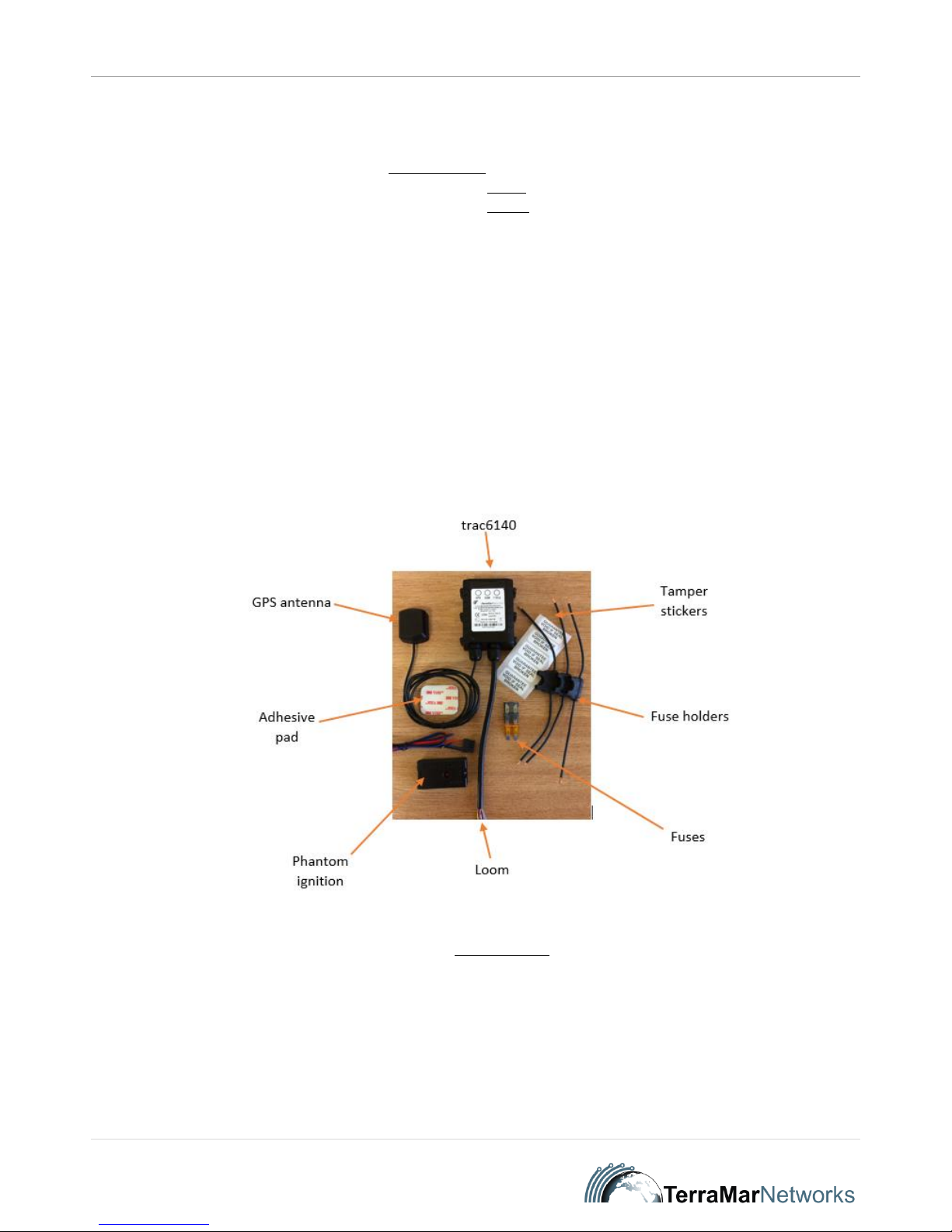
STANDARD PARTS – See Figure 1
trac6140 Device
Basic Loom (attached)
Phantom ignition sensor
GPS antenna
Fuse holders x3
Fuses x3 (1amp – 2amp – 5amp)
Tamper stickers x5
Cleaning pad
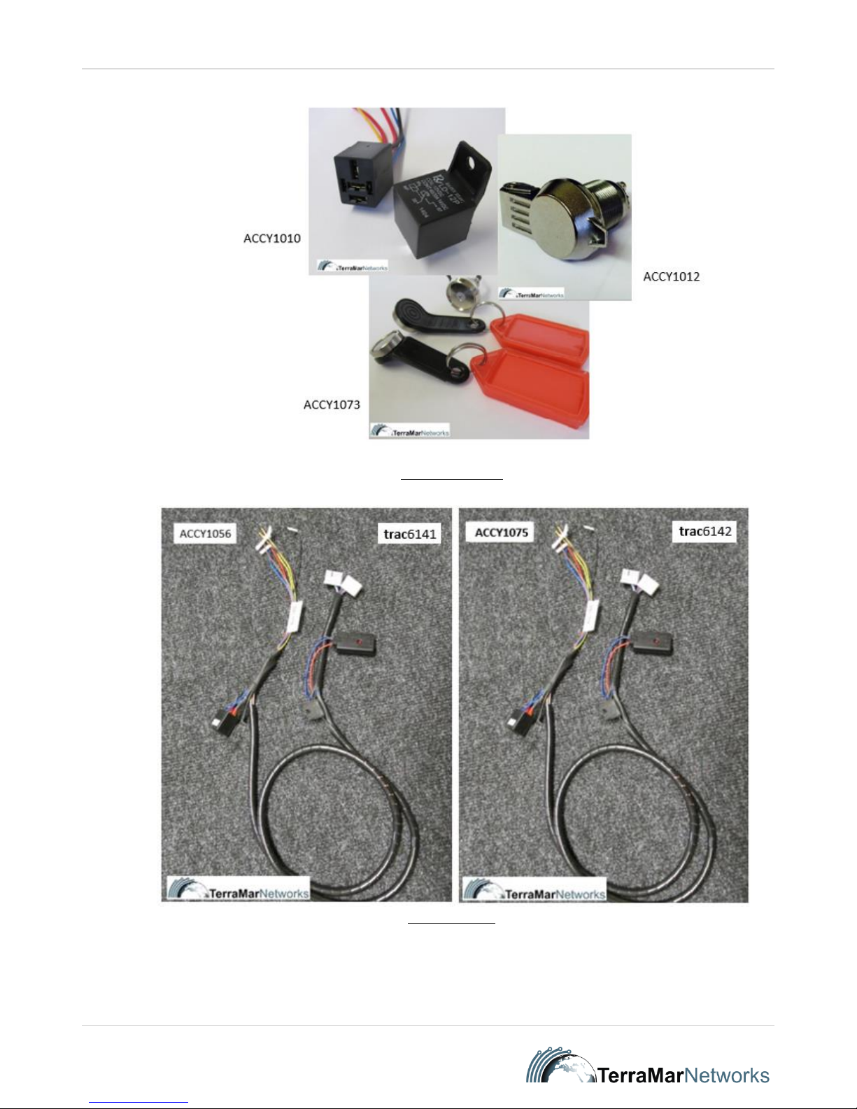
EXTRA PARTS AVAILABLE BY REQUEST/ORDER
Driver ID (ACCY1073) – see Figure 2
Panic Button (ACCY1012/ACCY 1013) – see Figure 2
Immobilisation circuit (ACCY1010) – see Figure 2
Complete Accessory loom 12V (ACCY1056) – see Figure 3 – includes phantom ignition sensor (PIS)
Complete Accessory loom 24V (ACCY1075) – see Figure 3
Fig 1: Standard Parts
I-021 - trac6140/1/2 - Installation Guide Ver. 2.1
tracpoint | Support Team
2 | P a g e
Fig 2: Application Options
Fig 3: Optional Looms
I-021 - trac6140/1/2 - Installation Guide Ver. 2.1
tracpoint | Support Team
3 | P a g e
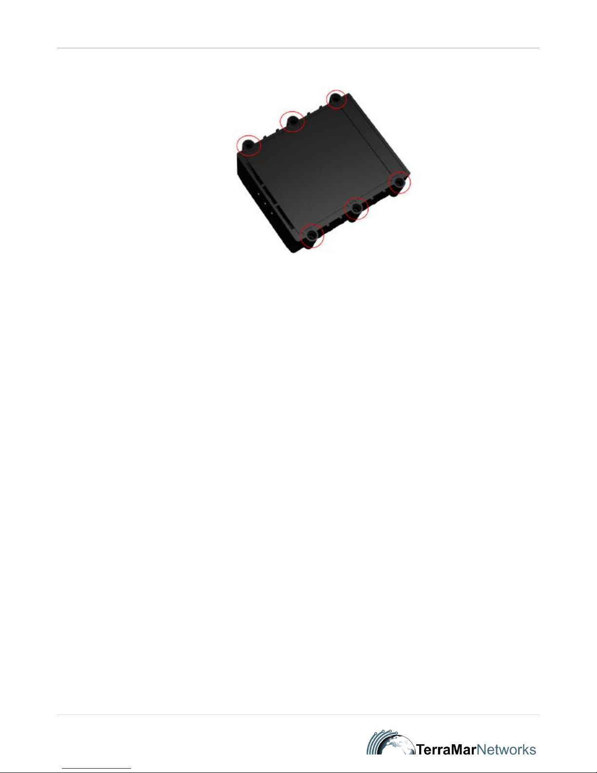
2. PREPARE DEVICE
Remove 6 Philips head screws from back of trac6140
Fig 4
Insert SIM card, if not already inserted in SIM card holder
Securely fix 6 Phillips head screws to Device
Prepare loom and identify the cables that are needed for your specific installation configuration
Apply one tamper sticker over the opening of the Device. Position the sticker such that, if the Device is subsequently opened, the tamper sticker will be torn.
3. MOUNT DEVICE IN VEHICLE
Find a secure location under the dash of the vehicle to mount the Device. Remove all panels necessary to give a good view of the area to be worked on. The
Device can be mounted using the self-adhesive pad on the back of the Device OR cable ties, securely fastened OR a combination of cable ties and the selfadhesive pad. Position the Device carefully – see Fig. 4 Device Positioning in this document. Device positioning is important: incorrect orientation of the Device
can result in false readings from the on-board 3-Axis accelerometer.
Mounting GPS antenna – see Section 4
DO NOT FIT DEVICE IN ENGINE COMPARTMENT
NEVER OBSTRUCT AIRBAGS, OR OTHER SAFETY FEATURES IN THE VEHICLE, WITH THE DEVICE OR ANY OF ITS ASSOCIATED WIRING
NEVER OBSTRUCT THE NORMAL OPERATION OF THE VEHICLE BY BLOCKING THE DRIVER’S VIEW
NEVER BLOCK THE DRIVER’S NORMAL OPERATION OF, AND ACCESS TO, INSTRUMENTS
ENSURE DEVICE IS NOT INSTALLED ON ANY SURFACE THAT MAY BE SUBJECTED TO LARGE FLUCTUATIONS IN TEMPERATURE
When deciding on the routing of cables, follow the proposed route of cables first, to ensure all lengths of cabling are adequate, e.g., power, earth, ignition feed,
etc. Ensure that the location of the Device allows adequate distance to the source of the feeds.
 Loading...