

Terra Exploration Group EZ Res Pro Technical User Manual
Terra EZ ResTM Pro
Earth R/P Analyzer
Technical User's Guide
2/3/4 Probes
Copyright 2016
Terra Exploration Group
Austin, Texas, USA
512-280-9600
www.TexGru.com

CONTENTS
Warning .............................................................................................. 1
I.Introduction .................................................................................. 3
II.Technical Specifications
1. Base Conditions and Working Conditions ............................ 4
2. General Specification ............................................................. 4
3. Intrinsic error and performance indicators under base
conditions ................................................................................... 8
III. Tester Structure ......................................................................... 8
IV.
LCD Di
V.Measuring Principle .................................................................. 10
VI. Operation Methods ..................................................................... 11
1.Switch On/Off .................................................................... 11
2.Battery Voltage Check ........................................................ 11
3.AC Voltage Measurement .................................................. 11
4.Earth Voltage Measurement ............................................... 12
5.4-wires Precise Earth Resistance Measurement ................. 13
6.3-Wires Earth Resistance Measurement ............................. 15
7.2-Wires Simple Measurement ............................................ 15
8.Soil Resistivity Measurement ............................................ 17
9.Backlight Control .............................................................. 18
10.Alarm Settings ................................................................. 18
11.Data Lock/Storage ............................................................ 18
12.Data Reading/Deletion ..................................................... 19
13.Data Upload ..................................................................... 19
splay .............................................................................. 9
............................................................. 4
VII.
. Battery Replacement ..............................................................19
VIII.Accessories ............................................................................ 20

Warning
Thanks for your purchase of Terra EZ Res Pro
Digital Earth Analyzer. For best results, thoroughly
read and completely understand this User's Guide.
The tester conforms to IEC61010 in design, production
and testing.
Under all circumstances, pay special attention to the
safe use of this device.
Avoid nearby use
phones to avoid electrical interference errors during device operation.
Pay attention to warnings and symbols shown on the device.
Make sure that device and accessories are in good
working order before use. Do not use if there are broken parts or
exposed areas of test wires. Do not touch probes while
measurement is in progress---risk of electrical shock!!!!
During measurement, do not touch bare conductors or circuits
under measurement.
Before measurement, please set rotary FUNCTION
switch to desired measuring position.
Confirm that connector plug of leads have been completely
inserted into device interface.
Do not expose to Earth Voltage exceeding 600V A.C. or D.C.
between probes and interface as this may seriously damage the
device.
of high-frequency signal generators like mobile
-1-

Do not operate device in the presence of flammables, as a spark
spark could initiate an explosion or fire.
Do not use device if test wires are damaged with uninsulated wire
exposed.
Do not expose the device to high temperatures, high humidity or
condensation.
Do not leave device exposed to direct sunlight
for expended periods to avoid excessive heating of electronics.
For battery replacement, remove testing wire from device
interface, and make sure that rotary FUNCTION switch
is in “OFF” position.
Dispose of used batteries in an appropriate manner.
When the meter displays battery low voltage symbol, replace
batteries.
The Tester has no
auto shut-off function. U
of
Testing complete, turn rotary FUNCTION switch to "Off"
If the Tester is not going to be used for a long period, remove
batteries to prevent battery corrosion and damage to the device.
This measuring device is only to be disassembled,
adjusted and/or and repaired by distributor-authorized
personnel---all other use will void warranty.
Risk of severe electrical shock exists through improper
use of this device
Device users must perform all operations
.
as instructed in this user's guide.
-2-

- 2 -
I.Introduction
The Terra EZ Res Pro is specially designed and
manufactured for measuring earth resistance, soil resistivity and
AC voltage. Utilizing state-of-the-art digital and micro-processing
technology precise earth resistance and soil resistivity
measurements can utilize 2, 3 or 4 probe arrays. The EZ Res Pro
possesses an unique function of wire resistance verification,
anti-interference capability and the ability to adapt to the
environment---all to ensure high precision, high stability and
reliability for prolonged and complicated measurements. The
EZ Res Pro is very effective in locating caves and tunnels as
well as underground water and mineral veins through the use
of electrical resistance tomography to accurately locate desired
subterranean anomalies. The EZ Res Pro is also widely used in
commercial power, telecommunications, oil field applications and
general construction.
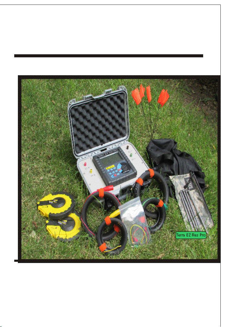
The Terra EZ Res Pro is composed of a
host device, monitoring software, testing wires,
communication wires, probes and a carrying case. The large
LCD display of device offers blue back-light for dark conditions
and a digital bar graph for ease of viewing. The Terra EZ Res
Pro can store sets of data of 300 individual readings, allowing
post-analysis via the included Data Collection and Analysis
Software, showing the maximum, minimum, and average
resistivity values. Included are alarm settings and an
alarm indicator as well as historical data access,
reading, preservation, report forms and printing.
The Terra EZ Res Pro Earth Analyzer may also
be called: Precise Earth Resistance Tester, 4-pole
Earth Resistance Tester, 2/3/4-pole Earth Resistance
Tester and/or Soil Resistivity Tester.
-3-
-4-
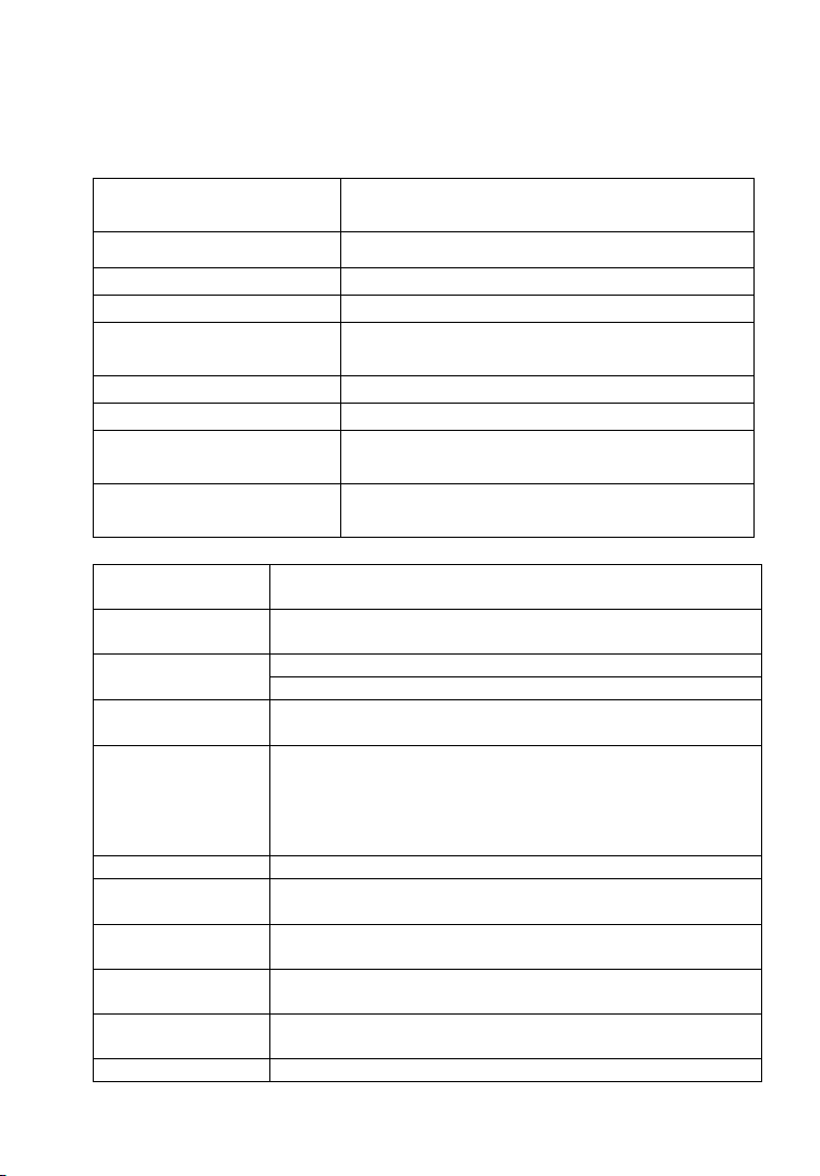
II.Technical Specifications
Working
Conditions
Ambient Temp
Ambient Humidity
<80%
Working Voltage
9V±1.5V
Auxiliary Earth
Resistance
<30kΩ
Interference Voltage
<20V
Interference Current
<2A
Electrode Distance
when measuring R
a>5d
Electrode Distance
when measuring ρ
a>20h
Function
Measurement of 2/3/4-pole earth resistance, soil
resistivity, earth voltage, AC voltage
Power Supply
Measurement
Range
Earth Resistance: 0.00Ω-30.00kΩ
Soil Resistivity: 0.00Ωm-9000kΩm
Measuring
Measuring
Test Frequency
128Hz/111Hz/105Hz/94Hz(AFC)
Short-circuit
Test Current
AC 20mA max
Open-circuit
Test Current
AC 40V max
Test Voltage
Wave
Sine wave
Electrode
Distance Range
Shift
Earth resistance: 0.00Ω-30.00kΩ, automatic shift
1. Working Conditions
Influence Description
2. General Specification
DC 9V(6 High Quality Alkaline C Cells 1.5V
continuous standby for 300 hours )
15F-105F
Modes
Methods
Precise 4-probe measurement, 3-probe
measurement and simple 2-probe measurement
Earth Resistance: rated current change-pole
method, measurement current 20mA Max
Soil Resistivity: 4-pole measurement
(Wenner or Schlumberger Arrays))
Earth Voltage: average rectification(between P(S)-ES)
Outside probes can be set up to 330' apart .
-5-
Soil Resistivity: 0.00Ωm-9000kΩm, automatic shift
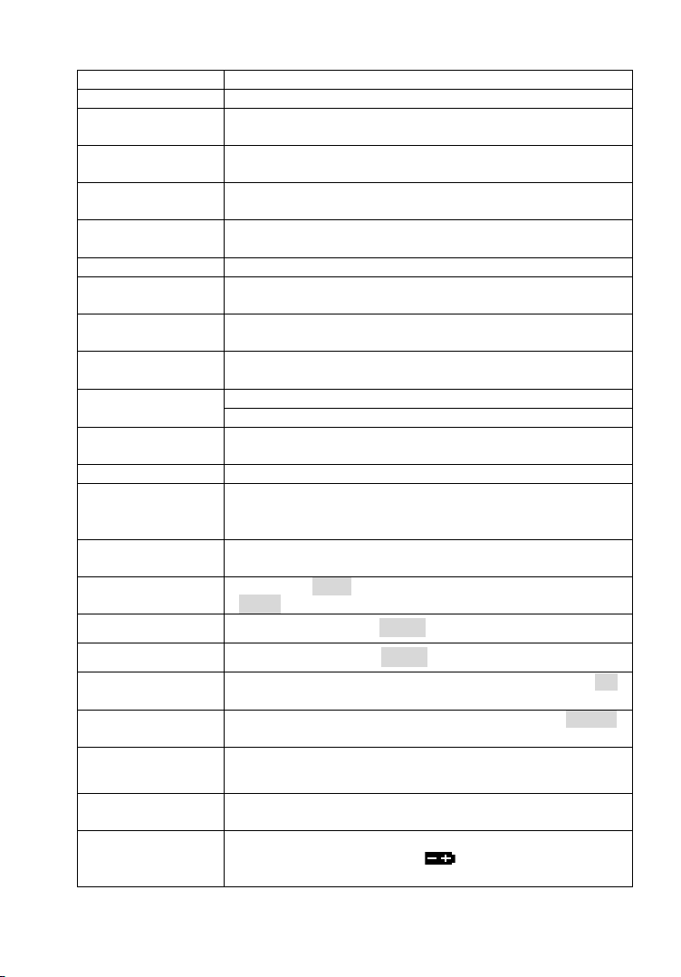
Backlight
Display Mode
4-digital super-large LCD display, blue screen
backlight
Measuring
Indicator
During measurement, LED flash indicator, LCD count
down display, progress bar indicator
LCD Frame
Dimension
LCD Window
Dimension
Dimension
Standard Test
Wire
Simple Test
Wire
Landscape
Measuring Rate
Voltage to ground: about 3 times/second
Earth resistance, soil resistivity: about 5 seconds/time
Measuring
Times
Over 5000 times (Short-circuit test, interval time
should be at least 30 seconds)
Circuit Voltage
RS232 Interface
Communication
Wire
Data Storage
Data Hold
Data hold function: “HOLD” icon display
Data Read
Data read function: “READ” icon display
Overflow
Display
Exceeding measuring range overflow function: “OL”
icon display
Interference
Test
Recognize interference signal automatically, “NOISE”
icon display when interference voltage exceed 5V
Auxiliary
Earthing Test
Can measure auxiliary earth resistance, 0.00KΩ30kΩ(100R+rC<50kΩ, 100R+rP<50kΩ)
Alarm Function
Battery Voltage
Spikes
Blue screen backlight, suitable for dim light use
5"×3"mm
4.9"×2.6"
L×W×H: 8.5"×7.5"×3.75"
4 wires: red 200 feet, black 200 feet, yellow 100
feet, and green 100 feet
2 wires: red and black 5.2 feet each
4 probes: 3/8" x 12"
Below AC 600V
RS232 interface, software supervision, storage
data can be uploaded to computer, saved or printed.
One RS 232 Cable
300 measurements, “MEM” icon storage indicator,
flash display “FULL” icon to indicate storage is full
When measuring value exceeds alarm setting value,
an alarm will sound.
When battery voltage decreases to about 7.5V,
low battery voltage icon will display, indicating
battery replacement is necessary.
 Loading...