

Page 1
Technical information
and assembly
instruction
Expenditure July 2008
TERRA-SW-TWIN_230V_installation_jul08-engl.cdr
Expenditure July 2008
TERRA-SW-TWIN_230V_installation_jul08-engl.cdr
heatpump
TV
V
IN
TERRA S/W-TWIN 230V
for
brine- or groundwaterplants
Type Basic
Page 2

Table of contents
Page
1. General Information
2. Heat pump
3. Heat source systems
4. Brine Horizontal Collector
5. Brine bore - hole system
6. Ground and Surface water systems
7. Advice for the Installation 20
8. Operation 21
9. Faults / Fault removal 22
1
2
2.1 Description 2
2.2 Rang of operation 2
2.3 Delivery content 2
2.4 Accessories 2
2.5 Technical Data- Brine heat pumps 3
Technical Data- Groundwater heat pumps 4
2.6 Operation limits 5
2.7 Technical dimensions 6
2.8 Installation 7
2.9 Hydraulic schematics 8
2.10 Connection ofthe heating side 12
2.11 Electrical scheme 12
2.12 Electrical connection 13
3.1 General information 15
4.1 Description 16
4.2 Rang ofApplication 16
4.3 Delivery Content 16
4.4 Technical Data 17
4.5 Installation schematic 17
5.1 Description
6.1 Description 19
6.2 Range ofApplication 19
6.3 Accessories 19
18
5.2 Rang ofApplication 18
5.3 Delivery Content 18
5.4 Technical Data 18
Changes in technology and Design reserve!
IDM-Energiesysteme GmbH,A-9971 Matrei i.O.,
C
(
General information for operation of the
heat pump.
Very important information for assembling and operation of the heat pump.
These informations are to be kept absolutely.
General information for assembling the
heat pump.
Place for the phone numberof your service partner.
Page 3

1. general information
Page 1
With the acquisition of this plant you have decided
yourself for a modern and economic heating system
Regular quality controls and improvements,
as well as functional tests in the factory, guarantees
a technically faultless device.
Read these documents attentively.
You will contain important notes and for the sure and
economical operation of the plant.
Installation and maintenance can involve dangers by
high Plant pressures, high temperatures and voltage-carrying Parts andbeing and must be done by experts.
Heat pumps may only be installed by competent experts and put intooperation onlyby a company which
is trained by IDM energy systems GmbH
For work on the heat pump all safety data in the corresponding documents, the sticker at the heat pump
itself and all the othersafety regulations haveto been
observed.
By transport, never incline the thermal pump more
then 15°.
The transportation packing should be removed just
after the thermal pump is positioned at the place of installation.
Terra heat pumps are very quiet in operation due to
their construction.
Nevertheless it is important that the heating room
should be positioned outside of sensitive to noise
living quarter and should be provided with a well closing door closing.
The heat pump isn't setup for the increased need of
heat for drying subfloor or carcass.
This must be done by equipment specially designed
for this task.
Tip for security:
Transport:
Sound emission:
Drying of subfloor orcarcass:
Service and maintenance:
Aregular maintenance as well as a check and
Care of all important plant parts guarantees at last a
safe and thrifty operation of the plant.
We recommend acontract formaintenance.
Cleaning:
If required, the Terra heat pump can be cleaned with
a damp cloth.The use of cleansers is not recommended.
Correct EC guidelines
Correct harmonized EN
Correct national norms/guidelines
Important safety reference
EC machine guideline (89/392/EEC)
EC low voltage guideline (73/23/EEC)
EC-EMV guideline (89/366/EEC)
EN378
EN60529
EN292/T1/T2
EN294
EN349
EN60335 1/2-40
EN55014
EN55104
ÖNORM M7755 2 (Austria)
:
The heat pump is filled with refrigerant. This
Cryogen is non-poisonous and not combustible.
In case of damage however, refrigerant is could flow
out of the plant, and could cause superseding of
oxygen.
Due to open fire, toxic disintegration products can ari-
se
By leaving refrigerant (smell)leave theinstallation site
immediately leaving and close the door.
Contact the customer service.
Works at and in the equipment are permitted only for
authorized experts
Reference to disturbances and error messages see
Page 20.
Page 4

2.1 Description
Heat pump with gas inlet cooled scroll-cachetcompressors, with large dimensioned stainless steel
heat exchangers as vaporizer, condenser on a robust frame with heat and noise emission insulated casing.
A console with all operational and safety equipment
is integrated in the body.
The device is prepared for the operation with a weather compensating flow temperature control (accessory).
The heat pump is accomplished in compact design
and the vaporizer is already built inside the heat
pump casing.
2.2 Range of operation
For a monovalent heating of one totwo family homes
with geothermal usage, whereby the house should
be equipped with a low temperature heating (e.g. under floor heating, wall heating or low temperature radiators)
2.3 Delivery content
2.4 Accessories
!
!
!
!
!
!
!
!
!
!
!
!
!
!
!
!
Heat pump aggregate with gas inlet cooledscrollcachet-compressors
stainless steel heat exchanger as condenser
stainless steel heat exchanger as vaporizer
coolant collector and dryer
Thermostatic expansion valve
coolant observing window
coolant heat exchanger
High and low pressure manometer
console with all operational and safety equipment
Thermorelais to protect the compressor
Internal motor protection
Robust frame
heat and noise emission insulated casing
Plastic brine-horizontal-collector Ø 25 x 2,3mm in
loops of 100m each, incl. manifold, connection
set and brine circulating pump
Brine-bore-hole Ø 40mm incl. connection set and
brine circulating pump
Manifold for brine bore-hole collector
!
5 flexible connection pipes
2. Heat pump for Brine or Groundwater operation
TERRAheat pumps operate with the safety coolant R
407 C, which circulates, if properly installed in a closed circuit and is practically no hazard for the environment.
As lower the maximal flow temperature is
designed as higher is the heat pump efficiency
Page 2
Page 5

- TWIN 2x8 S/W 2x10 S/W 2x12 S/W
Heating output at B 0°C/W 35°C in kW 15,34 18,24 22,56
for brine application
COP at B 0°C/W 35°C 4,02 4,07 4,08
Heating output at B 0°C/W 45°C in kW 14,86 17,68 21,66
Required electr. power at B 0°C/W 35°C in kW 3,82 4,48 5,54
B 5°C/W 45°C in kW 2,84 5,72 7,06
Electrical connection
Maximal current 34,6A 46,1 A 47,0 A
Blocked runner current 76 A 100 A 114 A
Upstream fuse 35 A, D 50 A, D 50 A, D
Fuse for control current 10 A 10 A 10 A
Maximal flow temperature 55 °C 55 °C 55 °C
Minimal heating water quantity 2 800 l/h 3 300 l/h 4.000 l/h
Minimal circulating brine quantity 3
Pressure loss on heating circuit 10 kPa 10 kPa 11 kPa
Pressure loss on collector circuit 14 kPa 15 kPa 17 kPa
Heating flow and return R 1 1/4" A.G. 1 1/4" A.G. 1 1/2" A.G.
Brine inlet and outlet R 1 1/4" A.G. 1 1/4” A.G. 1 1/2" A.G.
Used coolant R 407 C R 407 C R 407 C
Coolant quantity 2x2,0 kg 2x2,1 kg 2x2,6 kg
Compressor oil quantity 2x1,1 lt. 2x1,1 lt. 2x1,85 lt.
Amount of collector circuits 7 9 10
Total pipe length 700 900 1000
Brine quantity (mixture) 245 lt. 315 lt. 350 lt.
Recommended resp. integrated buffer
loading pump
Recommended pump power
Heating output at B 5°C/W 35°C in kW 17,86 21,02 26,70
Heating output at B 5°C/W 45°C in kW 17,12 20,34 25,46
Required electr. power at B 0°C/W 45°C in kW 4,80 5,66 6,88
Required electr. power at B 5°C/W 35°C in kW 3,78 4,48 5,58
Required electr. power at
230V/50 Hz 230V/50 Hz 230V/50Hz
for brine collector up to 40m
.600 kg/h 4 500 kg/h 5 500 kg/h
UPS 25-80 UPS 25-80 UPS 25-80
UPS 25-80 UPS 25-80 UPS 25-80
40 x 2,3 50 x 3,2 50 x 3,2
Note:
For large enough boiler rooms it is enough to have a natural venting with a min. venting opening dimensions,
like listed in the EN 378.
A mechanical venting of the boiler room is only required if the boiler room dimensions are not achieved.
5. Technical Data
Page 3
in line with the EN 14511in line with the EN 14511
Page 6

- TWIN 2x8 S/W 2x10 S/W 2x12 S/W
Heating output at W 10°C/W 35°C in kW 20,16 24,00 30,14
COP at W 10°C/W 35°C 10,08 12,00 15,07
for groundwater application
Heating output at W 10°C/W 45°C in kW 20,68 23,04 29,00
Heating output at W 15°C/W 35°C in kW 23,42 27,84 34,76
Heating output at W 15°C/W 45°C in kW 21,88 25,72 32,06
Required electr. power at
Required electr. power at W 10°C/W 45 °C in kW 5,02 5,98 7,38
Required electr. power at W 15°C/W 35 °C in kW 4,02 4,78 5,92
Required electr. power at
Electrical connection
A 26,1 A 47 A
Blocked runner current 76 A 100 A 114 A
Upstream fuse 50 A, D 50 A, D 50 A, D
Maximal flow temperature 55 °C 55 °C 55 °C
Minimal heating water quantity 3 500 l/h 4 200 l/h 5 200 l/h
Minimal groundwater quantity 3 700 l/h 4 500 l/h 5 500 l/h
Pressure loss on heating circuit 15 kPa 17 kPa 19 kPa
Pressure loss on collector circuit 16 kPa 18 kPa 18 kPa
Heating flow and return R 1 1/4” A.G. 1 1/4" A.G. 1 1/2" A.G.
Brine inlet and outlet R 1 1/4” A.G. 1 1/4" A.G. 1 1/2" A.G.
Used coolant R 407 C R 407 C R 407 C
Coolant quantity 2x2,0 kg 2x2,1 kg 2x2,6 kg
Compressor oil quantity 2x1,1 lt. 2x1,1 lt. 2x1,85 lt.
Recommended resp. integrated buffer
loading pump
W 10°C/W 35 °C in kW 3,88 2,68 5,88
W 15°C/W 45 °C in kW 5,04 5,94 7,36
Maximal Current 34,6
Sicherung Steuerstrom 10 A 10 A 10 A
230V/50Hz 230V/50Hz 230V/50Hz
UPS 25-80 UPS 25-80 UPS 25-80
Note:
For large enough boiler rooms it is enough to have a natural venting with a min. venting opening
dimensions, like listed in the EN 378.
A mechanical venting of the boiler room is only required if the boiler room dimensions are not achieved.
Page 4
Page 7
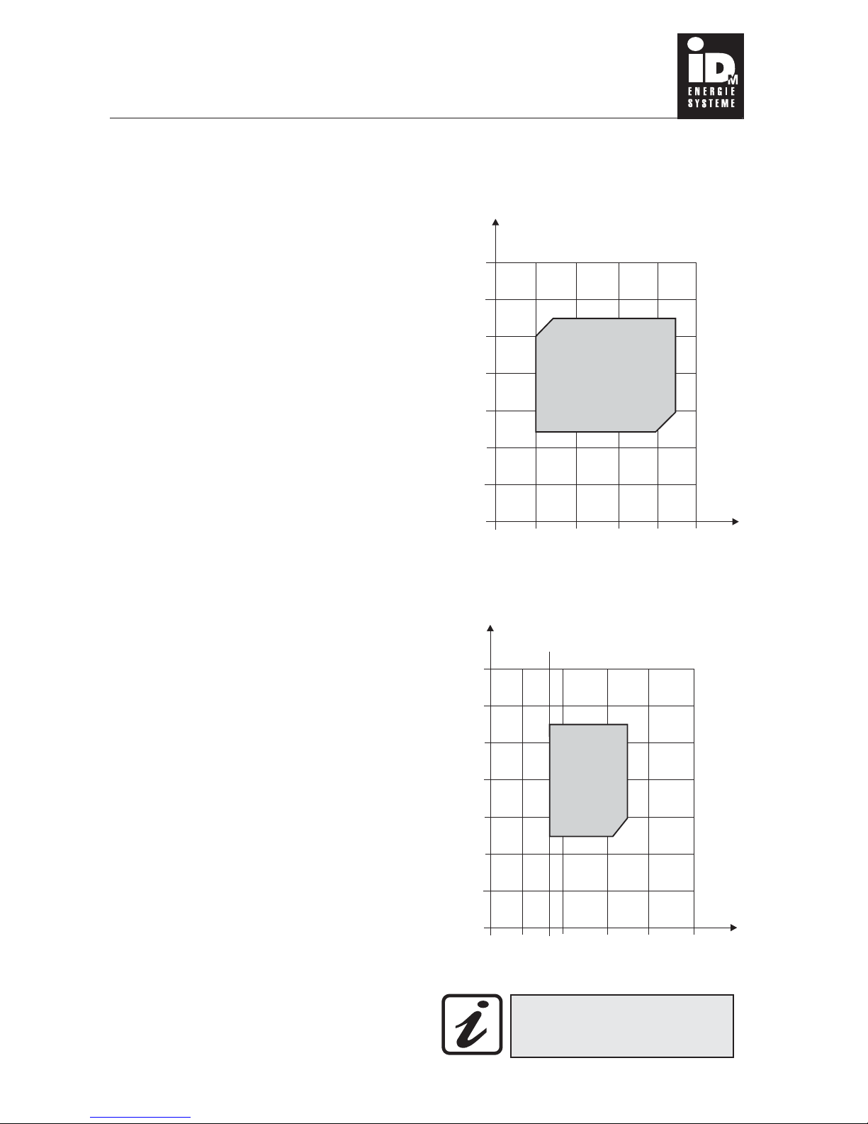
2.6 Operational limits
Seite 5
TERRA-S resp. TERRA-W heat pumps must be
only operated with the heat carrier medium brine
or Groundwater. Other heat carrier media are not
permitted.
Further it is not allowed to heat other fluids than
heating water.
(Heating water quality see page 10)
Heat pumps have natural pressure resp. tempe-
rature operation limits. (See illustration)
It is not allowed to operate the TERRAheat pump
outside these operational limits.
With groundwater heat pumps the groundwater
has to have a certain waterquality,see page18. If
one of those values is below or exceeds these limits it is not allowed to use the groundwater heat
pump with this groundwater.
There are several safety applications integrated
to protect the heat pump
A combined high and low pressure manometer which can be reset by switching the machine off and backon.
Max. flow temperature limit with will automatically reset.
A Thermorelais which can be reset by switching the machine off and back on.
Internal winding protection
With groundwater heat pumps: minimum temperature limit for the groundwater return temperature and integrated water pressure
switch.
Note:
?
?
?
?
?
°C
70
60
50
40
30
20
10
0
flow temperature
Range of application for brine heat pumps
Range of application for groundwater heat
-10010 20 3040°C
groundwater inlet temperature
°C
70
60
50
40
30
20
10
0
flow temperature
Minimum groundwater
inlet temperature: 7°C!
Also during the winter the
groundwater inlet temperature
must not drop below 7°C!
-20 -10 0 10 20 30°C
brine inlet temperature
Page 8
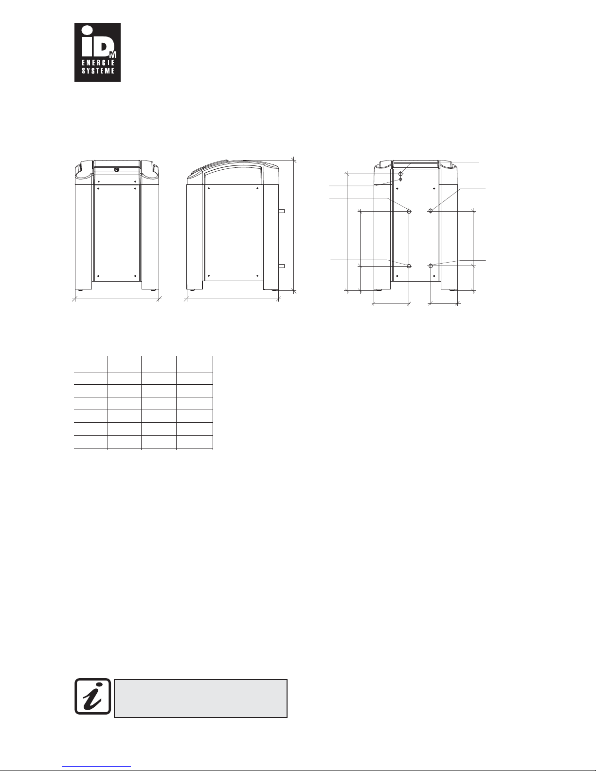
2.7 Technical dimensions
Page 6
front sidefront side
right sideright side back sideback side
762
B
A
TERRA 2x8S/W 2x10S/W 2x12S/W
A 750 750 750
B 1160 1160 1160
C 1025 1025 1025
D 465 465 465
E 465 465 465
2
1
3
2
1
3
Legend:
1 flow connection R 1 1/2” (use enclosed connection pipe 1 1/4” or 1 1/2”)
2 Opening for electrical connection with grind voltage
3 return connection
4 Brine resp. groundwater inlets
5 Brine resp. groundwater outlets
6 Opening Ø 50mm for electrical output
R 1 1/2” (use enclosed connection pipe 1 1/4” )
R 1 1/2” (use enclosed connection pipe 1 1/4” )
R 1 1/2” (use enclosed connection pipe 1 1/4” )
For brine heat pumps: see page 3
For groundwater heat pumps: see page4
Dimensions for connections:
or 1 1/2”
or 1 1/2”
or 1 1/2”
C
D
E
210
210
235310
6
4
5
6
4
5
On the backside of the heat pump is a sticker with the connecting description located
Page 9

Page 7
The TERRA heat pump must be installed in a frost
protected room by a certified Installation company.
The room temperature should be in between 5°C
and 35°C.
The installation in wet rooms or rooms that are at
high risk of dust or explosives is prohibited
The TERRA heat pump should be installed on a leveled, straight and capable ground (e.g. concrete) to
avoid noise conduction. If floor screed is used, the
screed and floor insulationhave tobe omit to ensure
a silent operation.
A minimum distance of 60cm is required in front of
and next to the heat pump. (See illustration on by)
The appropriated laws, regulationsand Normshave
to be taken into notice, specially the EN 378 Part 1..
To avoid noise conduction via the piping, the enclosed flexible connection pipes for the flow andreturn,
as well as for the brine in- and outlet resp. the
groundwater in- and outlet have to be used.
For a leveled installation of the TERRA heat pump
there are adjustable feet provided.
The en-
closed connection pipes must not be kinked!
2.8 Installation
min. 600750
850
TERRA
min. 600
The minimum distances have to be provided!
The minimum size of the boiler room has to be
provided!
The connection pipes have to be used!
Adjustable feed
Page 10

Page 8
2.8 Hydraulic schematics
System scheme 1:
TERRAheat pumpwith IDM-Hygienik
In this scheme the Hygenik is only used to provide
domestic hot water.
The heating is fed straight from the heat pump.
System scheme 1:
TERRAheat pumpwith IDM-Hygienik
It is only possible to use 1 Heating
circuit. The heating circuit must be a
pumped circuit (no mixer!) and is not
possible to use zoning control valves!
C
B9
B3
A6
heatpump
Buffer Hygienik
T
T
T
V1
P2
B2
T
A6
B9
B3
B1
layer separate plate
T
T
heatpump
Buffer Hygienik
T
B2
T
M1
V1
A
B
System scheme 2:
TERRA heat pump with IDM-Hygienik with
dividing membrane
The upper part of the buffer is loaded under priority
by a priority valve.
The lower part of the buffer is theheating buffer.
The heating circuit can be a pumped or mixed cir-
cuit, whereby it is recommended to fit a mixing valve.
System scheme 2:
TERRA heat pump with IDM-Hygienik with
dividing membrane
The sensor B2 has to be placed in the
lower buffer part.
C
The sensor B2 has to be
placed inside a sensor
pocket at the return.
P2
P1
Page 11

Page 9
A6
B3
B1
B2
T
B9
T
Buffer
Buffer Hygienik
heatpump
T
T
System scheme 3:
TERRA heat pump with IDM-Hygienik and extra
heating buffer
The Hygenik is only used to provide domestic hot
water and is loadedunder priorityby the priority valve.
The heating is supplied by an extra buffer.
The heating circuit can be a pumped or mixed cir-
cuit, whereby it is recommended to fit a mixing valve.
System scheme 3:
TERRA heat pump with IDM-Hygienik and extra
heating buffer
The sensor B2 has to be placed inside
the buffer.
The sensor B2 has to be placed inside
the buffer.
C
M1
V1
P2
P1
A
B
Page 12

C
2.10 Connection on the heating side
Wrong water flows by reason of wrong
pipe dimensions, wrong fittings or incorrect pump operation can cause fatal
disfunction.
Page 10
The appropriated laws, regulations and Norms for
heating installations are also valid for installations
that include heat pumps.
It is obligatory to fit a filter into the heating return
before the heat pump.
!
!
!
!
!
!
The circulating pump power has to matchthe installation (see technical data on page 3 and 4)
The safety and expansion installations for closed
heating systems relevant to EN 12828 have to be
provided.
The connection pipes should be as short as possible. The pipe dimensions have to match the required water flow.(See technical data on page 3 and 4)
The enclosed flexible connection pipes for the heating flow and return as well as for the brine and
groundwater circuit have to be used. The connection pipes can be shortened to a desired length
though not shorter than 60cm! Further the connection pipes must not be kinked!
At the highest pointof the pipes has to be an airvent
as well as a drain on the lowest point.
To avoid heat losses, the connection pipes have to
be insulated with an appropriate material.
Oxygen diffusion
If not diffusion proof plastic pipes for the under floor
heating or a vented heating system is used, it can
happen that, if steel pipes, steel radiators or steel buffer are installed, corrosion occurs onto these steel
parts.
Corrosion particles cansettle downinto the liquidizer
and can cause power losses ofthe heat pumpor high
pressure faults.
Therefore it should be avoided to use vented heating
systems or steel pipe installations in connection with
non diffusion proof underfloor heatingpipes.
Heating water quality
Depending on the Heating waterquality stoneformation (solids mainly from calcium carbon) especially
onto the heat exchanger surface can occur. With a
high Calcium hydrocarbon content it is a higher risk
of stone formation.
Therefore at Installations with a water hardness of
more than 14°dH resp. with a Calcium hydrocarbon
concentration of more than 2,5 mol/m³ the heating
water has to be treated. (Softened/desalted)
The Calcium hydrocarbon concentration
c(Ca(HCO3)2) of you heating water can be got from
your local water supplier.
The ph-value also needs to be checked and has to be
in between 8 and 9,5.
Page 13

2.11 Electrical scheme
The electrical connection has to be reported with
your local electricity supply.
The required size of the upstream fuse for the main
electric circuit can be seen within the technical data
on page 3and 4. It is importantto use a sluggish fuse
(characteristic D). The relevant wire diameter has to
be calculated by an electrician.
A to protect thecompressor isalready
integrated.
A for the brine or ground-
water pump and adjusted.
The heat pump is usually operated with a weather
compensating flow temperature control.
The connections to control the heat pump with a
are prepared inside the console.(Look
up the electrical connections on page 12)
The has to be inside certain tolerance
margins to insure a trouble free operation of the heat
pump (it can be asked at your local electricity supp-
lier)
Thermorelais
suitable motor protection
needs to be installed
room sensor
grid voltage
Main electricity connection
230 V/50 Hz
control current connection
230 V/50 Hz
activation of the brine or
groundwater pump
230 V/50 Hz
Page 11
The starting current limitation equipment can be inserted.The starting currents can be reduced around
approx. 50% (after pressure balance).
For TERRA 5 S till 30 S Art. Nr.: 351 211
motor protection
activation of the buffer loading pump
1x230V/ 50 Hz
Legend:
F1
S1
B1
fuse 6,3 A t
control switch On/Off
line filter
232122
1
Platine IO2, idm.multitalent.wp
S1
Line
Load
B1
Grid control currency
230V/50Hz
23
L
N
Pe
F1
operator device Mecmatic - MM,
back side
output connection input connection
Master Bus A
Slave Bus
RS 485
Master Bus B
RS 485
Systembus A
Systembus B
Buskable 8-polig
EEPROM IO2
EEPROM MM
Fuse 0,5 A t
18
Page 14

2.12 Electrical connection
Before connecting the heat pump, the plastic cover
has to be removed. Now the connectors are accessible. The connectors for the main and grid electricity
are separated. (See illustration resp. next page)
.
The cables have to have the relevant strength, see
point 2.5 on the technical data on page 3 and 4.
The required connections of devices from the micro
processor chip output have to be made out of flexible
cable with 1,5mm².
Grid connection: 230V/50Hz
Main electricity connection: 230V/50Hz
The electricity supply has to be disconnected before removal of the plastic cover!
The pumps have to be commissioned before the heat pump is put into operation!
All connections have to be tightened before the heat pump is put into operation!
The whole heating system has to be filled before the heat pump is connected to
the grid and put into operation, otherwise the circulating pumps could run dry.
Page 12
One comment to the problematic of Electro magnetically compatibility: From year to year more effort and
Know-How is required from manufactures and end
user of modern electronics because of Electro magnetically compatibility.
The amount of electrical applications is steadily rising and with them the potential for faults. Together
with power lines, transmitting devices and other telecommunication installations a invisible electro smog
is created.
These disturbances affect all systems, both, biological (us humans)and electronic systems. They cause
undesired faulty currents in many ways.
We can just guess the consequences ontobiological
systems, but you can measure the consequences onto electrical systems, and in heavy cases you can
even see them.
These disturbances can have various results:
Short term measuring faults
Long term measuring faults
Short term disruption of data connection
Long term disruption of data connection
Loss of data
Damage of the facility
All electrical applications like protection coils, motors, transmitters, high voltage power lines, etc. can
cause such disruptions, whereby the disturbance
can occur in many different linked ways. (Galvanic,
inductive, capacitive or radiation)
From our side everything undertaken isto protectthe
multi talent control against those disturbances.
(Hardware design, electro magnetic emission proof
console, grid filter,etc.)
!
!
!
!
!
!
The electrician is further responsible to avoid
eventual ways of disturbance during his installation.
Release the bolts
from the plastic cover and underneath
the yellow lid to remove the cover.
Page 15

Electrical connection for all brine and groundwater heat pumps of the type TERRA
Page 13
1 2 3 4 5 6 7 12 13 14 21 22 23 28 29 30
Main electricity con-
nection 230 V / 50 Hz
N Pe N Pe
brine resp. deep well
pump 230V
Control current con-
nection 230V/50Hz
N PeL L L
Pe
water pressure
switch (accessory)
Subsequent the necessary connections that are performed as inline connections are shown. The gray
connections have to be connected on site, whereby
the rest is pre connected already.
The wire diameter for the main electricity and for the
brine resp. the deep well pump wire has to be dimensioned corresponding to the technical data. (See page 3 and 4 for brine resp. groundwater systems)
24 25 26
Pe
External activation
EW contact
31
A
C
B
P<
Connecter description:
Main electricity connecter 230V 50Hz
:
1. Compressor 230V, pre connected
Connection
connection 230V/50H
(if no control is integrated): a potential free contact has to beconnected between connecter 24 and 25
a potential free contact has to be connected between connecter 25 and 26 (remove the pre installed bridge)
Connectern 1 to 3:
Connecter 4 to 7:
Connecter 8 to 11:
Connecter 21 to 23:
Connecter 24 and25:
Connecter 25 and 27:
brine resp. deep well pump
Control current z
External activation
EW barrier:
2. Compressor 230V, pre connected
Connecter 12 to 14:
27
Connecter 28 to 31:
Water pressure switch, at groundwater systems to
be installed on site, whereby the pre installed bridge
has to be removed; at brine systems the contact 28
and 30 has to be bridged.
1. Compressor 230V,
pre installed
8 9 10
11
2. Compressor 230V,
pre installed
Page 16

Page 14
3.1 General Information
The given required area for geothermal heat pumps
is related to average ground conditions (Soil, clay).
The required collector size and therefore the area
has to be increased for poor grounds (gravel).
Contact your IDM-partner for further consultation.
A pump trial run for 48 hours at the end of February
and a water analysis is recommended for the use of
groundwater.
Following criteria decides which the suitable Heat
source system is:
?
?
?
?
?
Is enough ground or surface water available?
Is the ground or surface water temperature also
during the winter above 8°C?
Is the ground or surface water quality sufficient
enough?
Is enough space for a horizontal collector availa-
ble?
Is a bore holeas aresult ofthe available space re-
quired?
The different heat source systems are described on
the following pages.
In various countries the use of geothermal heat has to be permitted by the water right authority. A corresponding request has to be made in time.
3. Heat source systems
Page 17

Page 15
4.1 Description
In this system there are plastic pipes Ø25 x 2,3mm
with a length of 100m each placed into the ground to
transfer the heat outof the ground. Depending on the
heat pump size there are more circuits necessary.
The brine mixture circulates inside these pipes. The
heat exchange between the brine and the coolant
happens inside the vaporizer set with a stainless
steel plate heat exchanger.
Following fittings are necessary for the installation:
Brass manifold with gate valves, safety blow off, manometer, pressure vessel, thermometer and a brine
circulating pump.
The enclosed flexible connectionpipes haveto befitted to avoid noise conduction. The connection pipes
between manifold and heat pump have to be made
on site, whereby galvanized pipes can't be used.
The brine mixing ratio has to be chosen up to -15°C
(= 30% anti freeze). If too much anti freeze is added,
the specific heat capacity of the brine decreases.
4.2 Range of Application
Suitable for all heat pumps of type TERRA S
4. Brine-Horizontal Collector
4.3 Delivery Content
?
?
Plastic pipes Ø 25 x 2,3mm in loops of 100m each,
the amount of loops depends on the heat pump output.
Connection set including
- Manifold with gate valves for each circuit
- Safety blow off
- Manometer
- 2 thermometers
- Pressure vessel
- Brine circulation pump
Connecting on Site: It is not allowed to use
any galvanized pipes! The enclosed flexible
connection pipes have to be used!
PE-plastic pipe
60
190
1 1/4”
Note:
Attention:
The used anti-freeze has to be permitted by
IDM-Energiesysteme GmbH.
The brine circuit pipes have to be insulated with a
suitable and diffusion proof insulationagainst condensing water.
Brine circulation pump and pressure vessel have
to be installed onto the flow.
The brine pressure vessel has to be connected
above the pipes.
The pump electrical connection box can't
show down! The pumpmotor can'tbe insulated!
!
!
!
Page 18

Page 16
4.5 Installation schematic
4.4 Technical Data
Pipe distance: about 80cm
Pipe depth: 110 120cm
Type S5 S7 S8 S10 S12
300 300 400 500 600
For the recommended brine circulation pump see technical data on page 3.
Amount of circuits
Total length of pipe, in meter
Required area in m²
Dimensions brine circuit. DN
Length of manifold
Brine mixture in liter*
* Brine mixture (30% anti freeze content), without the amount inside the connection pipes.
3345 6
240 240 320 400 480
25 25 25 25 25
180 180 240 300 360
105 105 140 175 210
The given required area for geothermal heat pumps is relates to average ground conditions (Soil, clay). The required
collector size and therefore the area has to be increased
for poor grounds (gravel). The circuitshave tobe bedded in
fine sand (0,3 0,5mm).
Contact your IDM-partner for further consultation.
Pipes from the manifold towards the cellar
An example for a TERRA 8 S-HGL heat pump with
4 circuits and a manifold connection inside the cellar.
For a lengthof 2m, where the pipes are brought
together,they have to be insulated.
The connection pipes have to be insulated with
suitable insulation, galvanized pipes can't be
used.
Aminimum distance of 1m has to be provided to
any water supply and drainage pipes as well as
to walls
Openings inside the wall have to be insulated
and made water proof.
A warning tape has to be bedded 0,5m above
the pipes.
An installation plan and photos have to be made.
The manifold connection can also be outside the
house inside a manhole.
?
?
?
?
?
?
Pipes towards the TERRA to cellar
manifold
Page 19

Page 17
5.1 Description
In this system the collector is made out of plastic pipes with a special pipe head. This vaporizing system
requires smallest space of allground vaporizers.The
bore-hole diameter is 125mm, the depth and collector length depend on the heatpump output. The brine
mixture circulates inside the pipes. The heat exchange between thebrine and the coolant happens inside
the vaporizer set with a stainless steel plate heat exchanger.
For the brine circuit connection is required: A brass
manifold with gate valves, safety blow off, manometer,pressure vessel,thermometer andbrine circulation pump.
The enclosed flexible connection pipes have to be
used to avoid any noise conduction. The connection
between manifold and heat pump has to be built on site, whereby itis not allowed to use any galvanizedpipes!
5.2 Range of Application
Suitable for all heat pumps of type TERRA S.
5. Brine bore-hole system
5.3 Delivery content
?
?
?
Collector plastic pipes, the size depends on the
heat pump output
Connection set including
- Safety blow off
- Manometer
- 2 thermometers
- Pressure vessel
- Brine circulation pump
Manifold has to ordered separately
Connection set
manifold
5.4 Technical data
Type TS 5 TS 7 TS 8 TS 10 TS 12
Amount of bore-holes 1 1 2 2 2
Total depth collector* m 80 100 130 150 190
Length of manifold L 60 60 120 120 120
Collector-Ø mm 40 40 40 40 40 40
Connection pipe -Ø DN 40 DN 40 DN 40 DN 40 DN 40
circulation pump** 25-60 26-60 25-60 25-80 25-80
Brine mixture*** 160 200 250 290 360
* The given collector depth is an average value and is depending on the condition of the ground.
** For the bore-hole collector: Type of pump: xx-xx = Grundfos UPS, xx/xx = Wilo Top S
*** Brine mixture (= 30% Proportion of anti-freeze), without contents of the collecting line
Connecting on Site: It is not allowed to use any galvanized pipes! The enclosedflexible connectionpipes have to be used!
Note:
!
!
!
!
!
The used anti-freeze has to be permitted by IDMEnergiesysteme GmbH.
The brine circuit pipes have to be insulated with a
suitable and diffusion proof insulationagainst condensing water.
Brine circulation pump and pressure vessel have
to be installed onto the flow.
The brine pressure vessel has to be connected
above the pipes.
The circuits have to be filled with the anti freeze
mixture from the pressure vessel on (because of
volume reduction at temperature drops during
operation)
The pipes have to rise for venting
Page 20

Page 18
6.1 Description
In this system ground or surface water is used as a heat source. In the case of groundwater usage the water is pumped out of a tap well, cooled down inside
the vaporizer and via the return well brought back into the ground. Ithas tobe ensuredthat the return well
is in flow direction of the groundwater downstream of
the tap well.
The heat exchange between the water and the coolant happens inside the vaporizer with a stainless
steel plate heat exchanger.
To protect the vaporizer there is an automated minimum temperature limit control and a water pressure
switch integrated and connected. A pressure reducing valve is necessary for the operation of the water
pressure switch. (To be fitted on site, see illustration)
The enclosed flexible pipes have to be used to avoid
noise conduction.The groundwater pipes have to be
built on site.
Note:
!
!
!
!
!
!
!
To avoid a blocking of the vaporizer, settle basins
have to be provided in case of high amounts of
particles inside the well water.(Sand, muck)
Flow and return pipes have to be frost protected,
with a slope towards the well.
The pipes inside the house have to be insulated
against condensing water.
A duct with electrical wires for the deep well pump
has to be placed from the tap well towards the heat pump.
The well cover has to be light and airtight to avoid
formation of algae and a silting of the well.
The well pump should be a deep well pump.
The well should be flushed for at least 48 hours af-
ter constructing to avoid a contamination of the
system.
6. Ground and Surface water systems
6.2 Range of Application
6.3Accessories
Waterinlet temperature
Min. water flow
Groundwater quality:
: min. +7°C!
: see chart on page 3
Following values have to be reached:
To be installed on site:
- Deep well pump with suitable pipe
- Motor protection switch for the deep well pump
- Waterfilter
- Watermeter withgate valve
- Pressure reducing valve
- Maybe Thermometer
?
Ph-value: 6,5 - 9
Chloride: < 100 mg/kg
Sulfate: < 50 mg/kg
Nitrate: < 100mg/kg
Manganese: <1 mg/kg
Free Carbonic acid: < 20 mg/kg
Ammoniac: <2 mg/kg
Iron: < 2 mg/kg
Free Chloride: < 0,5 mg/kg
Electric Conduction: > 50 S/cm und < 600 S/cm
Oxygen <2mg/kg
A pump trial run for 48 hours at the end of February
and a water analysis is recommended to check the
possibility for groundwater as a heat source.
*
*
*
*If those limits are exceeded,the vaporizerand pipes can get mocked up as well as the return well
can get silted.
mm
A water meter (if required by the water authority),
otherwise blind fitting
Filter (Mash width max. 0,6mm)
galvanized, plastic
or stainless steel pipes
deep well pump,
power depends on
the depth of well
Groundwater flow direction
min. 15 m
return well, tap well
Exhaustion well
pressure reducing valve
bypass to flush the well
Page 21

Page 19
7. Advices for the Installation
The heating and brine resp. groundwater circuits have to be pressure tested, neatly flushed,filled and carefully vented before the TERRA heat pump is put into operation.
Requirements for system start up:
The heating system as well as the buffer tank has
to be filled and vented.
In case of a brine heat pump the brine circuit has
to be filled with anti freeze (-15°C), flushed and
vented.
The electrical installation has to be finished.
It is only allowed to start the heat pump if the cir-
cuits on the cooling and the heating side are properly filled and the electrical connections arechecked.
Before starting up, the flow temperature limit has
to be checked and set. The shut off limit of 55°C
has to be checked and if needed the shut off temperature has to be changed.
The heat pump has a start up delay, so that the
compressor will just start after this time.
To drain the heat pump on the heating side frost
protected the heat pump return connection has to
be opened.
The groundwater return temperature limit has to
be set before start up so that the heat pump shuts
down at a water return temperature of 3°C.
?
?
?
?
?
?
?
?
Note:
At the heat pump console there is a particular switch
to flush and vent the brine or groundwater circuits.
(See illustration)
As soon as the electrical connections (main and control current) are installed, the brine resp. groundwater pump can put into operation by switching the
switch onto “Spülen” (“Flush”). The main switch at
the front of the console does not have to be switched
on.
Flush switch for the brine resp. groundwater pump
After the proper commission the switch
has obligatory be set onto “Automatik”.
Page 22

Page 20
8. Operation
The TERRA heat pump is switched on and off fully automated by the Multi talent control.
For a proper operationof thecontrols themanual has
to be looked up.
An annual service and maintenance of the installation by a customer service is recommended in concern of warranty claims.
Display:
Humming alarm light
main switch
heating control
(accessory)
operating and fault lights flow temperature
brine flush switch
fuse
Page 23

Page 21
9. Faults / Fault removal
C
In case of a series of High pressure, low pressure or Thermorelais faults, please contact your
customer service!
Customer service phone number:___________________________________
(
The heat pump is equipped with a variety of safety applications to protect the machine for possible faults.
If the heat pump is contrary to expectation not running, so the following things have to be checked:
Note: If the fault light “ ” or “ ” is shining, but no temperature is displayed at the referring thermostat, the main electricity supply is cut off. It can be a blocking
time of the electricity supply or a fault.
Over temperature Groundwater too cold
9.1 Is the green indicator light inside the main
switch shining?
9.2 Is the humming fault light shining (see illustration on page 20)?
If not:
Is the heat pump activated by the control? Look up
the referring control manual.
Is the fuse inside the heat pump console intact?
(For the position of the fuse look up the Description
of the heat pump)
Is the fuse of the primary control intact, e.g. the
EVA-system?
See referring system description..
Open the yellow lid and check the individual fault
lights, for this see 9.3 (right) and illustration on
page 12.
!
!
!
9.3 Is one of the 5 red fault lights shining?
High pressure fault
or Low pressure fault:
Motor protection:
Over temperature:
Groundwater too cold:
If one of those lights is shining switch off the
main switch and after a few seconds back on.
The heat pump is ready for operation again.
But still the function of the heating circuit
pumps should be checked.
If this light is shining the compressor was overloaded. Switch off the main
switch and after a few seconds back on. The
heat pump is ready for operation again. But still
the main electricity connection should be checked.
If this light is shining, the
heat pump has a too high temperature, has to
cool down and will switch back on automatically.
If this light is shining, the
groundwater return temperature out of the heat
pump is too low.
The groundwater circuit has to be checked.
1
2
3
4
5
Page 24

THE POWER-FAMILY
INBETRIEBNHAME - WARTUNG - SERVICE
PRAXISWISSEN FÜR VERKAUF UND TECHNIK
IDM-Servicetechnik
IDM-Akademie
Unsere Service-Techniker helfen gerne Vorort. Ihren
regionalen Ansprechpartner mit Kontaktdaten finden
Sie auf unserer Website
www.idm-energie.com
Das umfangreiche Seminarangebot für Fachleute bei der
IDM-ENERGIEFAMILIE steht für Sie jederzeit auf unserer
Website zur Verfügung.
Wir freuen uns über Ihre Anmeldung.
www.idm-energie.com
Your IDM- Partner:
IDM- ENERGIESYSTEME GMBH
Seblas 16 - 18
9971 Matrei in Osttirol
Telefon + 43 (0)4875 6172 - 0
Telefax + 43 (0)4875 6172 - 85
E-mail team@idm-energie.at
The IDM ZENTRALE IN MATREI IN OSTTIROL
www.idm-energie.com
Seminar- News www.idm-akademie.com
Wasserhygiene- News www.krankgeduscht.com
 Loading...