

Page 1

SolidPad LR7
User'sManual
Page 2

Page 3

©2014 roda computer GmbH. All rights reserved.
TRADEMARKS
Roda logo is a trademark of roda computer GmbH.
Microsoft and the Windowslogo are either registered trademarks or trademarks of Microsoft
Corporation in the United States and/or other countries.
Microsoft products are licensed to OEMs by Microsoft Licensing, Inc.,a wholly owned subsidiary
of Microsoft Corporation. The Bluetooth®word mark and logos are registered trademarks owned
by Bluetooth SIG, Inc.All other brand and product names are trademarks or registered trademarks
of their respective owners.
Images shown in this document may vary slightly from actual products at time of shipping.
Information in this manual is subject to change without notice.
Page 4

Page 5

Table of Contents
About This Manual
Related Information.................................................................................... 1
Conventions............................................................................................... 1
Basic Safety Guidelines
Intended Use.............................................................................................. 2
Maintenance and Operation Overview ....................................................... 2
Safety................................................................................................................
Electrical Hazards ...................................................................................... 3
Safety Guidelines for Mounting................................................................... 4
Environmental............................................................................................ 4
Radio Transmissions.................................................................................. 4
Cleaning and Servicing .............................................................................. 4
Regulatory and Certification ....................................................................... 5
Lithium Battery Safety Statement ............................................................... 6
Chapter 1. Introduction
About This Guide ....................................................................................... 7
Unpacking the Device................................................................................. 7
Technical Specifications ............................................................................. 7
SolidPad LR7 Configuration Options.......................................................... 9
3
Parts List...................................................................................................10
Identifying the Device................................................................................11
Dimensions ...............................................................................................16
Touch Screen Features.............................................................................17
Chapter 2. Getting Started
First Time Use...........................................................................................18
Charging the Battery..................................................................................18
Powering the Device On and Off.................................................................19
Installingthe Micro SIM Card ....................................................................20
i
Page 6

Removing the Micro SIM Card................................ ...................................21
Installingthe MicroSD Card................................................................ .......22
Removing the MicroSD Card.....................................................................23
Using the Stylus ........................................................................................24
Removing the Protective Film from the Display .........................................25
Chapter 3. Operation
Opening the I/O Compartment Cover........................................................26
Closing the I/O Compartment Cover..........................................................27
Connecting to External Cabling .................................................................28
Handstrap and Shoulder Strap..................................................................31
Installingthe Standard Battery ................................................................ ..36
Removing the Standard Battery.................................................................37
Connecting to a Wireless Network.............................................................38
Chapter 4. Using BIOS Setup Utility
When to Use the BIOS Setup Utility ..........................................................39
Accessing the BIOS Setup Utility...............................................................39
Installation an Operating System...............................................................40
BIOS Passwords.......................................................................................43
EC and BIOS.............................................................................................45
Chapter 5. Troubleshooting
Troubleshoot the Wi-Fi Connection ...........................................................50
Troubleshoot Operating the Computer ...................................................... 51
Call Product Support.................................................................................51
Chapter 6. Maintenance
Cleaning the Device ..................................................................................52
Returning the Device.................................................................................52
Contacting roda computer GmbH..............................................................52
ii
Page 7

About This Manual
The SolidPad LR7 User’s Manual provides instruction for qualified personnel to follow when setting
up a new SolidPad LR7 device.
This document is intended for use by qualified personnel to compliment the training and expertise,
not to replace it.
Conventions
Bolded or underlined text is used to emphasize the designated information.
A Note is used to provide additional information for the device or settings.
A Caution is used to warn against potential hazards or to caution against unsafe practices.
A Warning is used to identify immediate hazards for property damage, injury or death.
1
Page 8

Basic Safety Guidelines
The followingsafety guidelines are intended to help protect the user from injury and prevent
damage to the hardware.
n Do not place anything on the AC adapters power cable and make sure the cable is not
located where it can be tripped over or stepped on.
n Do not cover the AC adaptor as it reduces the cooling
n Do not use the AC adapter while it is inside the carrying case.
n Use only the AC adapter, power cord, and batteries that are approved for use with the device.
Use of another type of battery orAC adapter may cause risk of fire or explosion.
n If you use an extension cable with the AC adapter, ensure that the total ampere rating of
all products plugged in to the extension cable does not exceed the ampere rating of the
extension cable.
n If the device is moved between environments with very different temperature and/ or humidity
ranges, condensation may form on or within the device. Avoid damaging the device by
allowing sufficient time for the moisture to evaporate before using the device.
n When disconnecting cables, pull on the connector or on its strain relief loop, not on the
cable itself. When pulling out or plugging in the connector, keep it evenly aligned to prevent
bending the connector pins.
Intended Use
The SolidPad LR7 rugged tablet is equipped with multi-functionalterminals for stationary and
mobile applications in industrial environments such as logistics, warehousing, fleetmanagement,
manufacturing and the automotive industry.
Read the safety guidelines thoroughly before starting any servicing on the device. Read the
guidelines before powering up the device, and keep this document for later use.
The operator is solely responsible for any damage resulting from unauthorized modifications to the
device.
UnintendedApplication Use
The device is not designed for use in life-support systems or critical safety/security systems where
system malfunction can lead to the direct or indirect endangerment of human life. The operator is
fully responsible for using the device in these situations.
Maintenance and Operation Overview
The SolidPad LR7 is designed and manufactured according to strict controls and following the
stated safety regulations. The following list identifies incorrect operating uses of the SolidPad
LR7. Incorrect use of the SolidPad LR7 can lead to hardware damage, safety issues and
possible risk to personnel health:
n The SolidPad LR7 is under operation by untrained personnel;
n The SolidPad LR7 is not maintained as recommended;
n The SolidPad LR7 is not used as intended.
2
Page 9

Safety
Toprevent injury and damage, read th e following safety guidelines prior to operating the
device. The manufacturer assumes no liability for any and all damages arising from misuse or
noncompliance with these guidelines.
Electrical Hazards
Cleaning/Servicing: Power Off the SolidPad LR7
n Disconnect the SolidPad LR7 from power before cleaning or servicing it.
Power Adapter
Contact an authorized service personnel for repairs to the power pack. In the event of a blown
fuse after replacing the fuse, contact an authorized service personnel to avoid electrical shock.
Use only Supplied Power Cables
roda power cables meet industrial requirements for low-temperature flexibility, UV resistance, and
oil resistance. Use only supplied power cables from roda.
If other power cables are used, the following may apply:
n The operator is solely responsible for the resulting damage;
n All roda warranties are void.
EnvironmentalHazards
Do not use the SolidPad LR7 in locations near/with flammable gases or vapor.
The use of electrical equipment in explosive environments can be dangerous.
n Turn off the device when near a gas station, fuel depot, chemical plant or a place where
blastingoperations take place.
Environmental
Ambient Temperature
The SolidPad LR7 operates on the basis of a passive cooling concept which internal waste heat is
released via the housing surface and requires fresh airflow in the environment.
n Operating the SolidPad LR7 with no fresh cooling air may cause overheatingand damage
to the device.
n The operating environment should not be enclosed to prevent the cool air being heated by
the heat waste from the device.
Connecting and Disconnecting External Devices
Toprevent the considerable damage, the SolidPad LR7 and the external device should be
disconnected from power when connecting/disconnecting excluding USB devices.
3
Page 10

Only Use Authorized Accessories
Only use the supplied cables, power packs and other accessories that have been tested and
approved by roda. Contact your local distributor for further information.
Radio Transmissions
Permitted Transmission Power
Follow the national regulations for the maximum permitted transmission power.
The operator is solely responsible for this type of operation.
Radio Frequency Limited Locations
Considering the radio frequency limitation in hospitals and aircraft, the SolidPad LR7 can
only be installed with permission.
Industrial computers may affect the function of implanted medical devices such as pacemakers
and may cause malfunction.
Cleaning and Servicing
n Disconnect the SolidPad LR7 from power before cleaning or servicing.
n Never clean the SolidPad LR7 with compressed air, a pressure washer or a vacuum cleaner.
n If necessary, clean the housing of the SolidPad LR7 with a damp cloth.
n Clean the touch-screen with a nonabrasive cloth.
Regulatory and Certification
FCC
This equipment has been tested and found to comply with the limits for a Class B digital device,
pursuant to part 15 of the FCC Rules. These limits are designed to provide reasonable protection
against harmful interference when the equipment is operated in a commercial environment.
This equipment generates, uses, and can radiate radio frequency energy and, if not installed
and used in accordance with the instruction manual, may cause harmful interference to radio
communications. Operation of this equipment in a residential area is likely to cause harmful
interference in which case the user will be required to correct the interference at his own expense.
However, there is no guarantee that interference will not occur in a particular installation. If
this equipment does cause harmful interference to radio or television reception, which can be
determined by turning the equipment off and on, the user is encouraged to try to correct the
interference by one or more of the following measures:
n Reorient or relocate the receiving antenna.
n Increase the separation between the equipment and receiver.
n Connect the equipment into an outlet on a circuit different from that to which the receiver is
connected.
4
Page 11

n Consult the dealer or an experienced radio/ TV technician for help.
Any changes or modifications not expressly approved by the grantee of this device could void the user’s
authority to operate the equipment.
This device is operation in 5.15 – 5.25GHz frequency range, then restricted in indoor use only, Outdoor
operations in the 5.15 – 5.25GHz is prohibit.
This device is slave equipment; the device is not radar detection and not ad-hoc operation in the DFS
band.
Labeling Requirements
This device complies with Part 15 of the FCC Rules. Operation is subject to the following two
conditions: (1) this device may not cause harmful interference, and (2) this device must accept any
interference received, including interference that may cause undesired operation.
RF Exposure Information(SAR)
This device meets the government’s requirements for exposure to radio waves. This device is
designed and manufactured not to exceed the emission limits for exposure to radio frequency (RF)
energy set by the Federal Communications Commission of the U.S. Government.
The exposure standard employs a unit of measurement known as the SpecificAbsorption Rate,
or SAR. The SAR limit set by the FCC is 1.6 W/kg.Tests for SAR are conducted using standard
operating positions accepted by the FCC with the EUT transmitting at the specified power level in
different channels.
The highest SAR value for the device as reported to the FCC is 0.57 W/kg when placed next to the
body.
CE Marking
This product has passed the CE test for environmental specifications when shielded cables are
used for external wiring. We recommend the use of shielded cables. Please contact your local
representative for ordering information.
This product has passed the CE test for environmental specifications. Test conditions for passing
included the equipment being operated within an industrial enclosure. In order to protect the
product from being damaged by ESD (Electrostatic Discharge) and EMI leakage, we strongly
recommend the use of CE-compliant industrial enclosure products.
R&TTE
This device complies with the essential requirements of the R&TTE Directive 1999/5/EC.
CB
This device complies with the IEC 60950-1:2005+A1.
Lithium Battery Safety Statement
Lithium battery inside. Danger of explosion if battery is incorrectly replaced. Replace only with same or
equivalent type recommended by battery manufacturer.
5
Page 12

6
Page 13
Introduction
Chapter1. Introduction
The SolidPad LR7 is a rugged device equipped with 802.11, Bluetooth, GPS and GLONASS for
wireless data communications.
The SolidPad LR7 is a rugged 10.1” tablet computer capable of 1920 x 1200
resolution. The SolidPad LR7 supports the following operating systems:
n Windows
n Windows
n Windows
n Windows
n Android™ 4.4
About This Guide
The SolidPad LR7 User Manual provides instruction for qualified personnel to use as a guide for
setup of the device. This document is not intended to replace the training and expertise of the
end-user.
®
Embedded 8.1 Industry 64bits
®
Embedded Standard 7 64bits
®
7 Professional 64bits
®
Embedded Standard 8 64bits
Unpacking the Device
Before you begin the installation or configuration process make sure to inspect all components
and accessories. Contact your representative if there are any missing or damaged items. See
“Contacting roda” on page 52.
Technical Specifications
Table 1. Technical Specifications
Item Description
Display 10.1-inch LED Backlight, 1920 (W) x 1200 (H) WUXGA
Touch screen 10-point capacitive touch screen
Brightness 1000 nits
CPU Intel Dual Core Atom E3827 1.75 GHz (Bay Trail)
Operating System Windows®Embedded 8.1 Industry 64bits
RAM DDR3L@1333 MHz 4 GB RAM (optional: 8 GB)
Storage mSATASSD 128 GB (optional: 256 GB)
n Standard hot swappable battery: 10.8V, 4500mAh, Li-polymer
Battery
n External hot swappable battery: 10.8V, 9000mAh, Li-polymer
(optional)
n Backup: 3.6V, 2500mAh
Power Supply AC 100V ~ 240V, 50~60Hz input; 19VDC@3.42A, 65W
Dimensions (W x H x L) 280 mm (11”) x 23 mm (0.9”) x 195 mm (7.7”)
Weight 1.33 kg (2.93 lbs)
7
Page 14

Introduction
Item Description
Wireless
WLAN Wi-Fi IEEE 802.11 a/b/g/n/ac
Bluetooth Bluetooth V4.0
WWAN (Optional) Optional for 3.5G or 4G LTE
Sensor
Sensor Gyroscope, G sensor, E-compass, Light sensor
I/O
Docking Connector 12-pin
DC-IN Jack x1
Micro SIM Card Slot x1
MicroSD Slot x1
Audio Jack x1; headphone / microphone combo
USB 3.0 x1; type A
USB 2.0 x1; type A
RS-232 x1 (optional for USB 2.0; type A)
Micro HDMI x1
Ethernet x1
Security
TPM TPM1.2
BIOS On/Off for I/Os Yes
Data Collection
n Front: 2.0 Mega-Pixels camera
Camera
GPS Yes
NFC Optional
Barcode Reader Optional
Magnetic Stripe Reader Optional
n Rear: 5.0 Mega-Pixels camera with LED auxiliary light and
Auto-focus
Smart Card Reader Optional
Rugged Specifications
Drop 183 cm (5 feet), 26 drops on plywood
8
Page 15
Item Description
n Vibration (MIL-STD-810G Method 514.6 Category 4, Fig
n Drop (MIL-STD-810G Method 516.6 Procedure IV)
n Mechanical shock (MIL-STD-810G Method 516.6 Procedure I,
MIL-STD 810G
n Operation and storage temperature (MIL-STD-810G Method
n Humidity MIL-STD-810G Method 507.5 Humidity Procedure II
IP rating IP65
Introduction
514.6C-1, Fig 514.6C-2, Fig 514.6C-3)
Procedure V)
501.5 and 502.5)
Aggravated Cycles (Fig 507.5-7)
Operating Temperature
Range
Storage Temperature
Range
Humidity 5-95% without condensation
-20°C (-4°F) to 50°C (122°F)
-30°C (-22°F) to 70°C (158°F)
SolidPad LR7 Configuration Options
The followingoptions are available for the SolidPad LR7:
n NFC module
n Barcode reader
n Magnetic stripe reader
n Smart card reader
n High capacity battery
n Digitizer
n 3.5G or 4G LTE
9
Page 16
Introduction
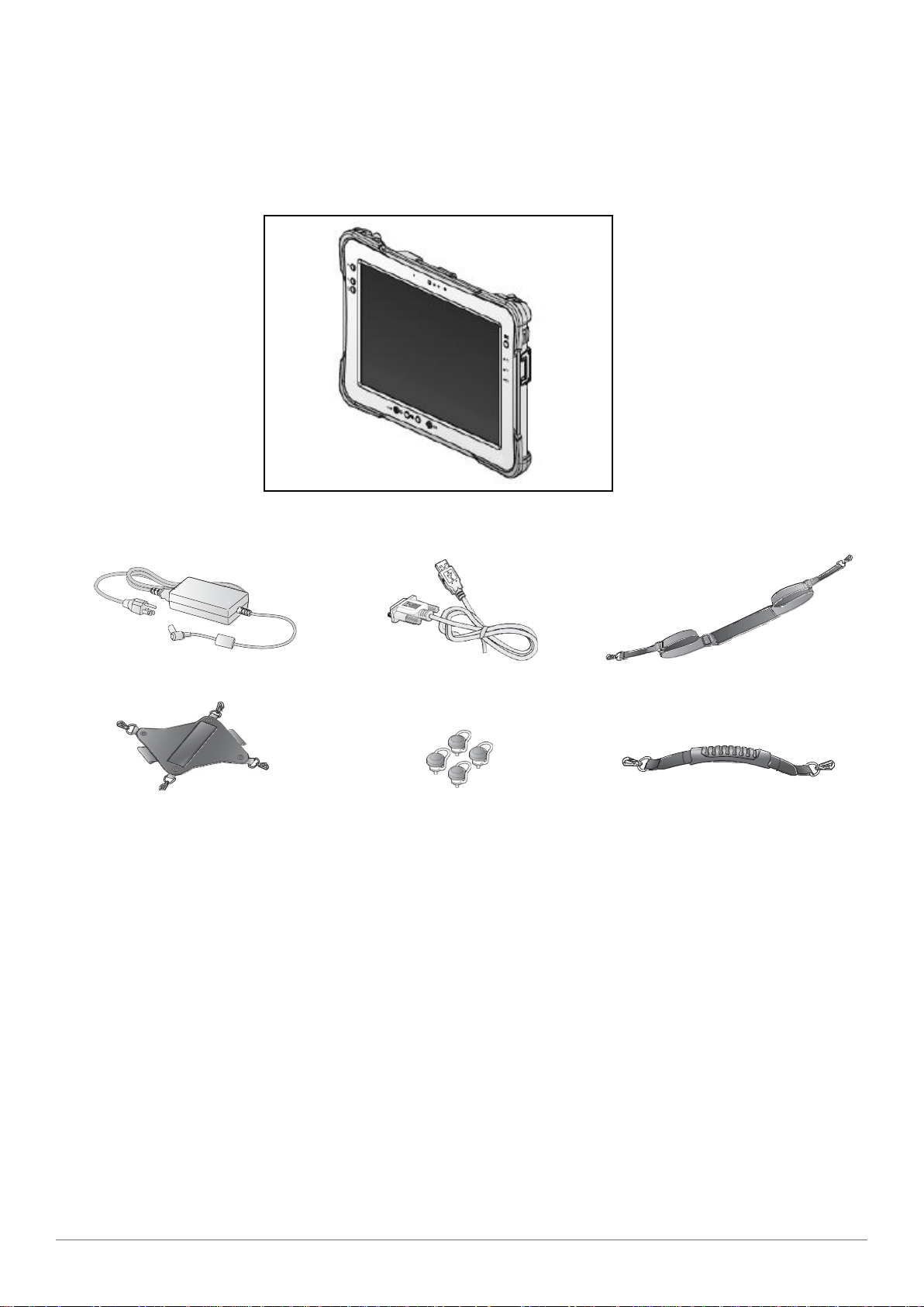
Parts List
The SolidPad LR7 is shipped with the following items. All other accessories are sold and ordered
separately. For help, contact your local roda sales representative. See “Contacting roda” on page
52.
SolidPad LR7
PowerAdapter RS-232 to USB 2.0 Cable
4-Point Handstrap
Hitch D-rings 2 Point Carrying H andle
(Attaching straps)
2 Point Shoulder strap
10
Page 17
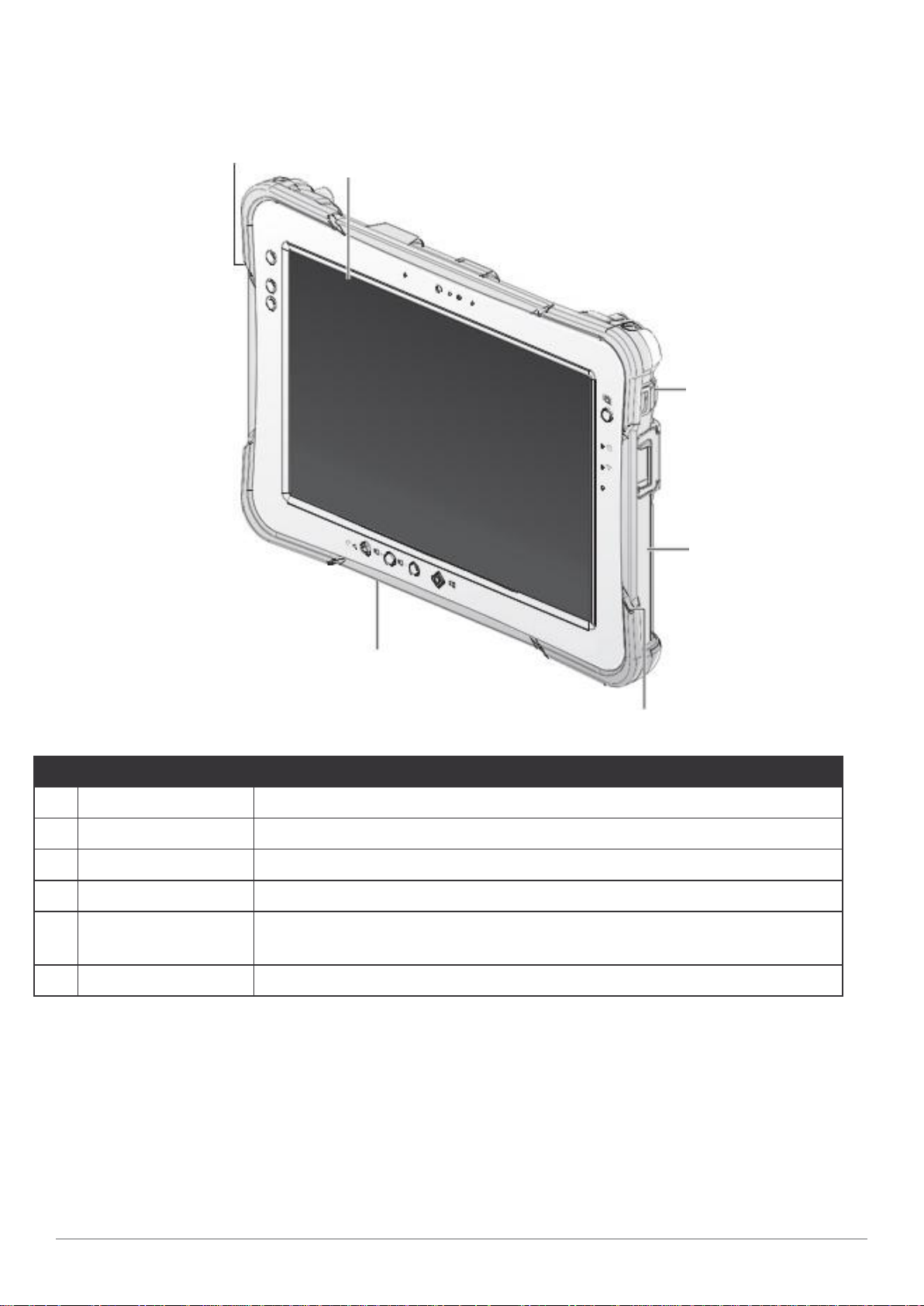
Identifying the Device
Introduction
Overview
1
2
f
f
f
3
f
4
6
Table 2. Overview
No Item Description
1 Left view
2 Front view
3 Rear view
4 Right view
5 Rubber bumpers
6 Bottom view
See “Side View” on page 14 for further information.
See “Front View” on page 12for fu rther information.
See “Rear View” on page 15 for further information.
See “Side View” on page 14 for further information.
Easy to grip rubber bumpers enable the rugged tablet to withstand
shocks and drop foruse in demanding environments.
See “Bottom View” on page 13 for further information.
Figure 1. Overview
5
11
Page 18
Introduction
7
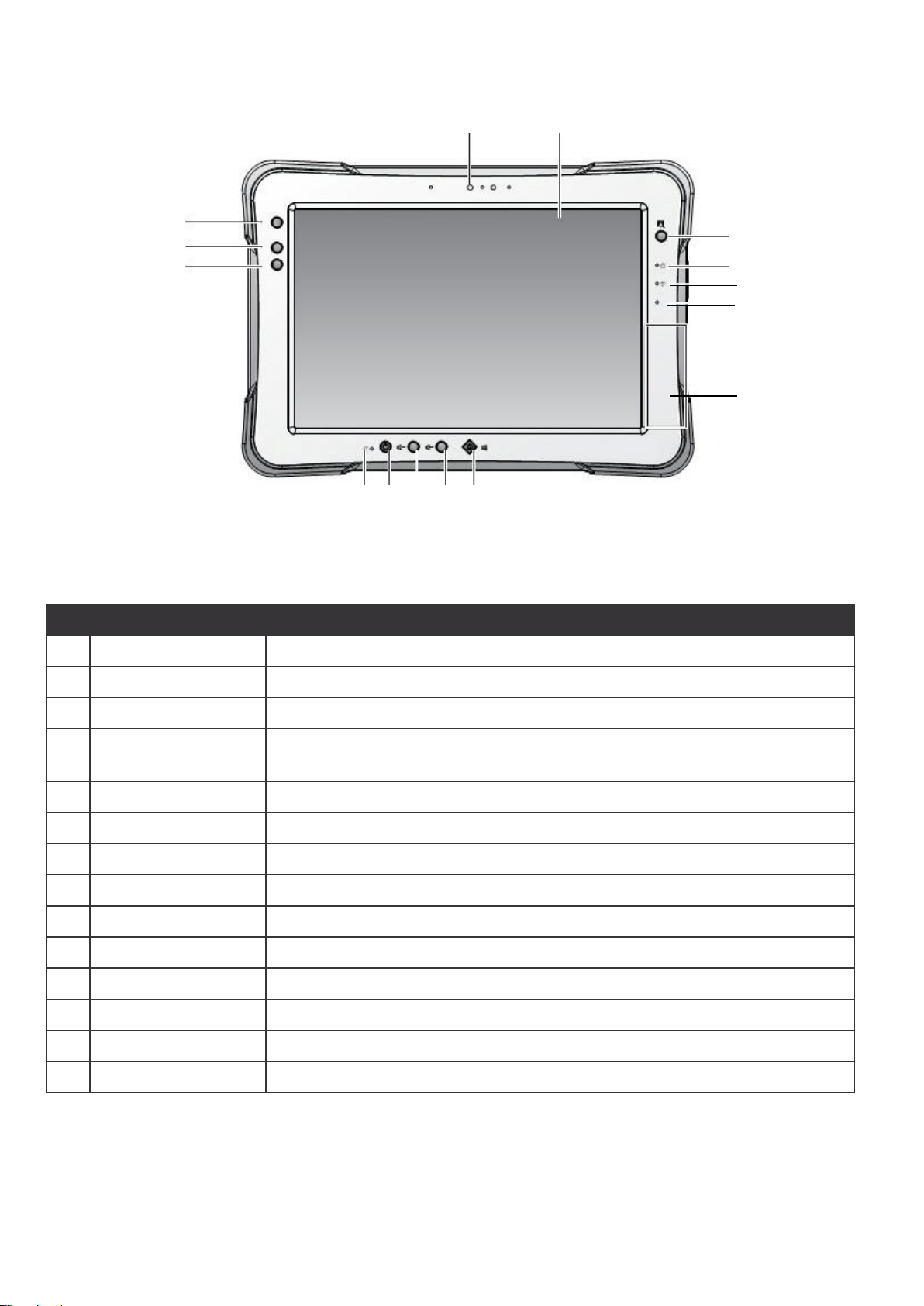
Front View
1 2
14
13
12
fn
f1
f2
11 10 9 8
Figure 2. Front View
Table 3. Front View
No Item Description
1 Front camera 2.0 Mega-Pixels camera.
3
4
5
fn
6
7
2 Touch screen 10-pint capacitive touch.
3 Barcode trigger If barcode scanner is installed, press to scan.
4 Power LED
The power LED lights when the device is on or when the battery is
being charged.
5 Wi-Fi LED The Wi-Fi LED lights to indicate Wi-Fi is enabled.
6 FN LED The FN LED lights when the function switch on.
7 NFC sensing area For detecting NFC devices. (Optional)
8 Home key Windows®8 home key.
9 Volume - Volume decrease.
10 Volume + Volume increase.
11 Power key Turns the SolidPad LR7 on or off.
12 F2 key Programmable function key.
13 F1 key Programmable function key.
14 FN key Programmable function key.
12
Page 19
LED Status
1
Table 4. LED Status
Item Status Description
Green: On Power on / not charging
Amber: On Power on / charging
Introduction
Power
FN
Wi-Fi
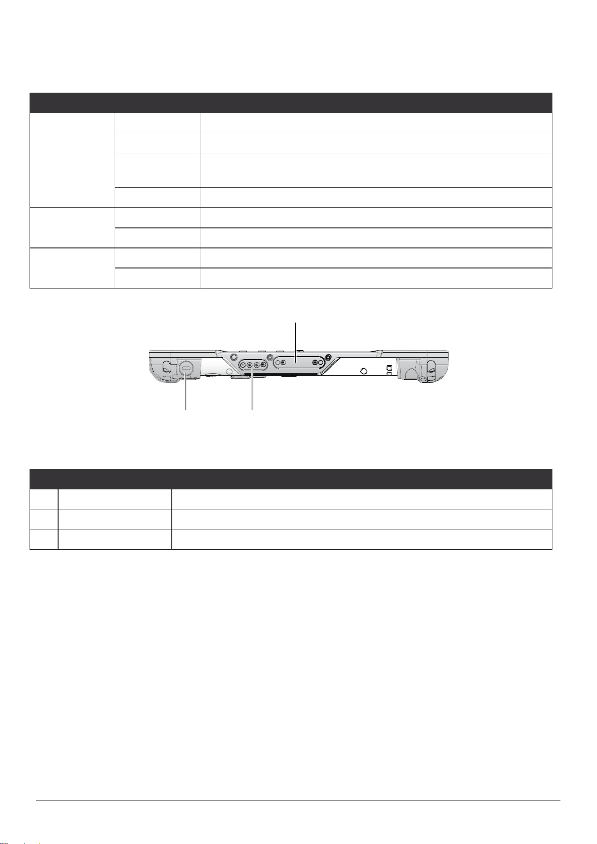
Bottom View
Amber:
Blinking
Off Power off / charging full / no battery
Green: On FN function switch on
Green: Off FN function switch off
Green: On Wi-Fi on
Green: Off Wi-Fioff
Low power < 10%
2 3
Figure 3. Bottom View
Table 5. Bottom View
No Item Description
1 Docking connector 12 pin connector for docking onto a station.
2 Kensington lock Lock the SolidPad LR7 to a stationary object for security.
3 Pass-through Dual pass-through for WLAN, GNSS and WWAN.
13
Page 20

Introduction
Side View
Left view Right view
12
1
2
3
4
2.0
ON OFF
SIM SD
6
13
7
8
3.0
9
10
11
5
Figure 4. Side Views
Table 6. Side View
No Item Description
Left I/O
1
compartment
cover
Open to access the USB 2.0 port.
14
15
2 Micro HDMI Connect HDMI devices to the SolidPad LR7.
3 MicroSD slot Insert microSD card in to the slot.
Left I/O
compartment
4
cover
5 Tether hole Stylus can be tethered to it.
6 USB 2.0 Connect USB devices to the SolidPad LR7.
7 Battery switch Switch to ON to provide power from the battery.
8 Micro SIM slot Insert micro SIM card for 3G or 4G LTE communication function.
9 USB 3.0 Connect USB devices to the SolidPad LR7.
10 Audio jack Connect a headphones or external speakers.
11 Ethernet Connect the SolidPad LR7 to an Ethernet (RJ-45) cable.
12 DC-IN jack Insert power connector to charge battery.
13 RS-232
14 DC-IN cover Open to access the DC-IN jack.
Open to access the left I/O ports.
Connect the SolidPad LR7 to a serial device or USB devices via a
RS-232 to USB cable.
Right I/O
15
compartment
cover
14
Open to access the right I/O port.
Page 21

Rear View
1
2
3
4 4
Introduction
6 5
Figure 5. Rear View
Table 7. Rear View
No Item Description
1 Battery Toinstall a battery, an external battery is optional.
2 Rear camera 5.0 Mega-Pixels camera with LED auxiliary light.
3 Barcode reader For installing a barcode reader (Optional).
4 Securing holes
5 Expansion bay Remove the cover to find the barcode reader connector.
6 Stylus holder Place stylus here.
Secure the bumpers and the D-rings for the handstrap and shoulder
strap.
15
Page 22

Introduction
28
1
28/ 11
19.5
/ 7.7
Dimensions
The following image lists the device dimensions without add-ons (mm/inches).
/ 11
fn
f1
f2
7
7.
/
fn
Figure 6. Front View Dimensions
2.3 / 0.9
2.3 / 0.9
Figure 7. Side View Dimensions
16
Page 23

Introduction
Touch Screen Features
Always use the point of the stylus for clicking or making strokes on the touch screen.
Never use an actual pen, pencil, or sharp/abrasive object on the touch screen.
The stylus is used as if it were a pen or pencil.Touch the screen with the tip of the stylus then
remove the stylus from the screen.
After each use, replace the stylus in the stylus holder for proper care and to preserve the life of the
stylus.
Using a stylus is similar to moving the mouse pointer then left-clicking icons on a desktop
computer screen.
The followingactions are available through the use of the stylus:
n Open applications
n Choose commands in menu
n Select options in dialog box or drop-down menu
n Drag the scroll bar
n Drag across the text to select content
n Place the cursor in a text box before typing
A right click is generated by tapping the mouse icon in the system tray. After tapping, the mouse
icon highlights the right button of the icon in red. The next touch screen tap is treated as a right
click. The mouse icon returns to the left button highlighted in red so subsequent taps are treated
as left clicks.
A stylus replacement kit is available.
17
Page 24

Getting Started
3
SIM
SD
Chapter2. Getting Started
This section provides an outline of the steps necessary to setup a new SolidPad LR7.A detailed
guide follows the listed items, see as follows.
For additional technical assistance, contact your roda representative. See “Contacting roda” on
page 52.
It is recommended to installing or remove accessories on a clean, well-lit work
surface. Toprotect yourself and the device from electrostatic discharge, wear antistatic wrist straps or place the device on an anti-static mat.
First Time Use
1.
Open the left I/O compartment cover. See “Opening the I/O Compartment Cover” on page
26.
2.
Switch the switch to the ON position.
ON OFF
Figure 8. Switching the Battery Switch
Close the left I/O compartment cover. See “Closing the I/O Compartment Cover” on page
3.
27.
Charging the Battery
When you use the AC adapter to connect your SolidPad LR7 to a power outlet, the standard
and external (optional) battery will automatically begin to recharge.
Whilethe battery is charging, the power LED will be active. Whenthe battery is fully charged, the
power LED is lit a solid green.
Flip open the DC-IN cover to expose the DC-IN jack.
1.
Figure 9. Opening the DC-IN Cover
18
Page 25

Connect the AC adapter to the DC-IN port.
2.
Figure 10. Connecting the AC Adapter
After charging the battery, disconnect the AC adapter and close the DC-IN cover.
Insert one end of the cover first and angle the cover to seat it in place.
1.
Push in the cover to seal the DC-IN compartment.
2.
Getting Started
Figure 11. Closing the DC-IN Cover
The DC-IN cover must be inserted correctly to prevent internal damage to the device.
Powering the Device On and Off
Powering On the Device
Only power on the SolidPad LR7 after connecting all of the peripherals and cabling.
1.
Press and hold the power button until the screen lights. The device runs through the start up
sequence and powers up.
Figure 12. Power On the SolidPad LR7
19
Page 26

Getting Started
Powering Off the Device
n Start screen:
Tap
> Shut down.
n Desktop screen:
Tap and hold at the bottom left corner of the Desktop screen.
1.
2.
Tap Shut down or sign out > Shut down.
n Both Start screen and Desktop screen:
Display charm bar and tap Settings.
1.
Tap Power > Shut down.
2.
Installing the Micro SIM Card
The device includes a micro SIM card slot for cellular and wireless connection. Only a micro SIM
card is supported in the slot.
Check with your network or cellular service provider for availability and cost rates.
Power down the device.
1.
Open the left I/O compartment cover. See “Opening the I/O Compartment Cover” on page
1.
26.
Locate the micro SIM slot in the left I/O parts.
2.
Figure 13. Left View: Locating the Micro SIM Slot
Left view
2.0
ON OFF
SIM SD
Micro SIM Slot
3.0
20
Page 27

Take the micro SIM card from its packaging.
3
SIM
SD
3.
The micro SIM card has a corner missing.Align the SIM card with the slot making sure that
4.
the corners match.
Insert the micro SIM card and press it in until an audible click sounds.
5.
ON OFF
Figure 14. Installing the Micro SIM Card
6.
Close the left I/O compartment cover. See “Closing the I/O Compartment Cover” on page
27.
Getting Started
Removing the Micro SIM Card
1.
Power down the device.
Open the left I/O compartment cover. See “Opening the I/O Compartment Cover” on page
1.
26.
2.
Locate the micro SIM slot in the left I/O parts.
Left view
2.0
ON OFF
SIM SD
3.0
Micro SIM Slot
Figure 15. Left View: Locating the Micro SIM Slot
21
Page 28

Getting Started
3.4.Press
the
micro
SIM
card
in and
release
it.
The
card
springs
out.
Grasp the micro SIM card and remove it from the slot.
Figure 16. Removing the Micro SIM Card
5.
Close the left I/O compartment cover. See “Closing the I/O Compartment Cover” on page
27.
Installing the MicroSD Card
The device supports microSD card for easier data storage.
Power off the SolidPad LR7.
1.
Open the left I/O compartment cover. See “Opening the I/O Compartment Cover” on page
1.
26.
Locate the microSD slot in the left I/O parts.
2.
Left view
2.0
ON OFF
SIM SD
MicroSD Slot
3.0
Figure 17. Left View: Locating the MicroSD Slot
22
Page 29

The microSD card has a beveled edge. Align the microSD card with the slot making sure that
3.
SIM
SD
3.
the corners match.
4.
Insert the microSD card and press it in until an audible click sounds.
ON OFF
Figure 18. Installing the MicroSD Card
Close the left I/O compartment cover. See “Closing the I/O Compartment Cover” on page
5.
27.
Removing the MicroSD Card
Getting Started
1.
Power off the SolidPad LR7.
Open the left I/O compartment cover. See “Opening the I/O Compartment Cover” on page
1.
26.
Locate the microSD slot in the left I/O parts.
2.
Left view
2.0
ON OFF
SIM SD
MicroSD Slot
3.0
Figure 19. Left View: Locating the MicroSD Slot
23
Page 30

Getting Started
3.4.Press
the
microSD
card
in
and
release
it.
The
card
springs
out.
Grasp the microSD card and remove it from the slot.
Figure 20. Removing the MicroSD Card
5.
Close the left I/O compartment cover. See “Closing the I/O Compartment Cover” on page
27.
Using the Stylus
Following the information below when using a stylus:
n Use only the included stylus to touch the screen. Do not place any objects on its surface and
do not press down strongly with sharp-pointed or hard objects that may leave marks (e.g.,
nails, pencils and ball point pens).
n Use the stylus only for touching the screen. Using it for any otherpurpose may damage the
stylus and result in scratches on the screen.
n The pointer cannot follow the stylus movement if you move the stylus too quickly.
Tomake a selection, tap the screen once with the stylus. Todouble-click, tap twice without
pausing. Todo a right-click, tap the screen once and hold the tip of the stylus on the screen, the
right-click icon appears.
24
Page 31

Getting Started
Removing the Protective Film from the Display
The front display of the SolidPad LR7 is protected during transport by a transparent film. This film
should remain on the front display during assembly to avoid damage to the front display surface.
Only remove the film once all of the assembly work has been completed.
Figure 21. Removing the Protective Film
25
Page 32

Operation
Chapter3. Operation
Opening the I/O Compartment Cover
Place the device display side down on a clean work surface.
1.
2.
Locate the I/O compartment cover.
Left view
Right view
Left I/O
2.0
Compartment
Cover
Left I/O
ON OFF
SIM SD
3.0
Compartment
Cover
Figure 22. Side View: Locating the I/O Compartment Cover
Unlock the latch. (Only available for the left I/O compartment cover)
3.
Right I/O
Compartment
Cover
Pull out the I/O compartment cover.
4.
26
Figure 23. Unlocking the Latch
Figure 24. Openin the I/O Compartment Cover
Page 33

Closing the I/O Compartment Cover
1.
Place the device display side down on a clean work surface.
2.
Locate the I/O compartment cover.
Left view Right view
Operation
Left I/O
2.0
Compartment
Cover
Left I/O
ON OFF
SIM SD
3.0
Compartment
Cover
Figure 25. Side View: Locating the I/O Compartment Cover
3.
Flip the I/O compartment cover and install.
Right I/O
Compartment
Cover
Figure 26. Installing the I/O Compartment Cover
Lock the latch. (Only available for the left I/O compartment cover)
4.
Figure 27. Locking the Latch
The I/O compartment cover must be inserted correctly to prevent internal damage to the device.
27
Page 34

Operation
3.0
SIM
SD
Connecting to External Cabling
Toprevent damage to the device, connect all cabling and accessories before
powering up the device.
Connect USB Cabling
The SolidPad LR7 have one USB 3.0 and one USB 2.0 ports for connecting USB devices, such as
a digital camera, scanner, printer, modem, and mouse. The USB ports support USB 2.0 or USB
3.0 devices.
1.
Open the left I/O compartment cover. See “Opening the I/O Compartment Cover” on page
26.
Connect to USB device via USB cable.
2.
Figure 28. Connect USB 2.0 Cabling
Figure 29. Connect USB 3.0 Cabling
28
Page 35

Connect Ethernet Cabling
3.0
3.0
The SolidPad LR7 provide have a Ethernet port for connecting Ethernet.
Use a shielded cable is required to maintain emissions and susceptibility compliance.
Open the left I/O compartment cover. See “Opening the I/O Compartment Cover” on page
1.
26.
Connect LAN cable to Ethernet port on the SolidPad LR7.
2.
Operation
Figure 30. Connect Ethernet cabling
Connect Audio Cabling
For higher audio quality, you can send sound through external audio devices such as speakers,
headphones, or earphone using audio connector.
1.
Open the left I/O compartment cover. See “Opening the I/O Compartment Cover” on page
26.
Connect the audio cable.
2.
Figure 31. Connect Audio Cabling
29
Page 36

Operation
SIM
SD
Connect Micro HDMI Cabling
Connect to HDMI devices via micro HDMI cable.
1.
Open the left I/O compartment cover. See “Opening the I/O Compartment Cover” on page
26.
2.
Connect micro HDMI cable to micro HDMI port on the SolidPad LR7.
ON
OFF
H
D
M
Figure 32. Connect Micro HDMI Cabling
Connect RS-232 Cabling
Connect to RS-232 devices via RS-232 cable.
Open the right I/O compartment cover. See “Opening the I/O Compartment Cover” on page
1.
26.
Align the RS-232 cable with the port in the device and connect it.
2.
Turn the locking screws on the cable to secure it to the device.
3.
Figure 33. Connect RS-232 Cabling
30
Page 37

Operation
Handstrap and Shoulder Strap
The SolidPad LR7 is equipped with a handstrap and a shoulder strap to provide users safety use.
For more information, see “Connecting the Handstrap” on page 31 and “Connecting the
Shoulder Strap” on page 33.
Connecting the Handstrap
Remove the screws securing the bumpers.
1.
2.
Install the D-rings.
Make sure the D-rings are tightly secured before installing the handstrap.
Figure 34. Removing the Screws
Figure 35. Installing the D-rings
31
Page 38

Operation
Connect to lock the handstrap on the D-rings.
3.
When the handstrap is installed, the stylus can be placed under the strap.
Removing the Handstrap
Unlock the handstrap from the D-rings.
1.
Figure 36. Connecting the Handstrap
Figure 37. Removing the Handstrap
2.
Remove the D-rings.
32
Figure 38. Removing the D-rings
Page 39

3.
Secure
the
bumper
and
thePM-
521
with
screws.
Figure 39. Securing the Screws
Connecting the Shoulder Strap
1.
Remove the screws securing the bumpers.
Operation
Install the D-rings.
2.
Make sure the D-rings are tightly secured before attaching the shoulder strap.
Figure 40. Removing the Screws
Figure 41. Installing the D-rings
33
Page 40

Operation
3.
Attach the clips to the D-rings to attach the shoulder strap.
Figure 42. Connecting the Shoulder Strap
Removing the Shoulder Strap
1.
Press in the clips to release them from the D-rings.
2.
Remove the clips.
Remove the D-rings.
3.
Figure 43. Removing the Shoulder Strap
34
Figure 44. Removing the D-rings
Page 41

4.
Secure
the
bumper
and
thePM-
521
with
screws.
Figure 45. Securing the Screws
Connecting the Carrying Handle
1. Attach the clips to the metal loop on the bumper.
Operation
Figure 46. Connecting the Carrying Handle
Removing the Carrying Handle
1. Press in the clips to release them from the metal loop.
2. Remove the clips.
Metal
Metal
Loop
Loop
Figure 47. Removing the Carrying Handle
35
Page 42

Operation
Installing the Standard Battery
The followinginstructions are for both standard and external batteries. The external battery is an
optional component. Only use components specifically designed for this device. Contact your local
representative for ordering information.
Make sure the power switch is switched to ON before installing the standard/external
battery. See “First Time Use” on page 18.
1.
Place the device display side down on a clean work surface.
2.
Locate the battery.
Locking Switch
Release Button
Battery
Figure 48. Rear View: Locating the Battery
36
Page 43

4.
Secure
the
bumper
and
thePM-
521
with
screws.
Align the tabs on the battery with the slots on the chassis.
3.
Angle the battery in place and set the tabs in the chassis slots.
4.
Lower the raised end of the battery and press in place until an audible click is heard.
5.
Figure 49. Installing the Battery
Slide the locking switch on the top-left side to lock the battery.
6.
Operation
Figure 50. Locking the Battery
Make sure the latch is securely locked to prevent the battery from falling.
Removing the Standard Battery
Place the device display side down on a clean work surface.
1.
Locate the battery.
2.
Locking Switch
Release Button
Battery
Figure 51. Rear View: Locating the Battery
37
Page 44

Operation
Figure 52. Unlock the Battery
4.
Press and hold the release button as shown in the image to release the battery.
Hold the battery and angle the left side up to remove.
5.
Figure 53. Removing the Battery
Connecting to a Wireless Network
Before you can make use of the SolidPad LR7wireless functions, you need to connect to a
network. The following is a set of procedures for connecting to a wireless network.
1.
Before beginning, make sure your Wi-Fi setting is enabled and you are within range of a
wireless network. If your Wi-Fi setting is disabled, proceed to step 2.
n Look at the Network icon located at the right side of the taskbar. If the icon displays an
X in a red circle, you are not within range of a wireless network. Move to a different spot
until the Wi-Fi icon changes status indicating availability to a wireless network.
From any screen, open the Charms bar by sliding your finger inward from the screen’s right
2.
edge. The Charms bar displays along the screen’s right side.
In the Charms bar, tap Settings to open the Settings menu.
3.
In Settings, tap the Network icon to display the Networks connection settings.
4.
5.
The Wi-Fi menu displays. By default, the Wi-Fi menu is set to Off. Tap the bar next to Off to
toggle Wi-Fi to On. This enables the Wi-Fi option.
6.
Once W-Fi is enabled a listing of all available wireless networks displays. The wireless
networks with the strongest signal are atop the list.
7.
Select the network you want to connect to, and tap the Connect button. You can tap the
Connect Automatically check box if you connect to this network frequently. If you connect
to the network, you are finished with the process.The network is considered an Open
unsecured network, no passoword is required.
38
Page 45

3.
Slide
the
locking
switch
on
the
top-left
side
to
the
unlock
position.
8.
If a password is required, type the password in the Enter the network security key
9.
field.Alternatively, you can also push the WPS button on your router to begin the security
handshake.
Tap Next to finish the connection process.
10.
You have successfully connected to a wireless network.
Operation
39
Page 46

Using BIOS Setup Utility
Chapter4.
Your ruggedized tablet has a BIOS setup utility which allows you to configure important system
settings, including settings for the Boot and AP menus as well as the device’s basic settings--the
system reads the basic settings during initialization in order to boot correctly
UsingBIOSSetupUtility
When to Use the BIOS Setup Utility
You need to run the BIOS Setup utility when:
n Restoring to BIOS settings to factory default
n Modifying specific hardware settings
n Modifying specific settings to optimize system performance
n Installing Windows 7 operating system
Accessing the BIOS Setup Utility
The BIOS Setup Utility screens shown in this chapter are for your reference only. The
actual images or settings on your tablet computer may differ.
The BIOS Setup Utility program may have been updated after the publication of this
manual.
Torun the BIOS Setup Utility, use the following procedures:
Perform one of the following:
1.
n If the SolidPad LR7 is powered off
Press the Power button to start up the device. The power LED lights.
Quickly press and hold the Windows Home key until the BIOS Post screen displays.
n If the SolidPad LR7 is powered on
Press the Power button to shut down the device.
Quickly press and hold the Windows Home Key until the BIOS Post screen displays.
The BIOS POST screen appears as shown.
From the BIOS POST screen select App Menu to open the BIOS Setup Utility.
2.
40
Figure 54. BIOS POST Screen
Page 47

Using BIOS Setup Utility
Due to the device’s fast boot up and boot down time, there is only a small time frame of a few
seconds between the release of the Power button and the opportunity to press the Windows Home
key.
TheApp Menu displays.
Figure 55. BIOS Setup Utility: App Menu Screen
Installation an Operating System
Setting Up a Windows 7 Installation Environment
There are several settings in BIOS that must be modified before you can install a Windows 7
operating system.
Use the following guidelines to prepare the BIOS environment:
n Step 1: Enable CSM Support
1.
Access the BIOS Setup Utility, see “Accessing the BIOS Setup Utility” on page 39.
Navigate to APP Menu > Main > Boot Features.
2.
3.
Locate the CSM Support setting and tap the drop-down menu to display the options.
41
Page 48

Using BIOS Setup Utility
Tap Yes to enable CSM support.
4.
Figure 56. Main > Boot Features
n Step 2 Enable Legacy Boot
Access the BIOS Setup Utility, see “Accessing the BIOS Setup Utility” on page 39.
1.
Navigate to APP Menu > Main > Boot Features.
2.
Locate the Legacy Boot setting and tap on the menu to select On enable legacy boot.
3.
n Step 3: Enable USB 2.0 Support
1.
Access the BIOS Setup Utility, see “Accessing the BIOS Setup Utility” on page 39.
2.
Navigate to APP Menu > Advanced > Miscellaneous Configuration.
3.
Locate the USB Controller Select drop-down menu and tap on it.
40
Figure 57. Main > Boot Features
Page 49

Page 50

Using BIOS Setup Utility
Tap USB 2.0 from the menu list. USB 2.0 is now enabled for the device.
4.
Figure 58. Advanced > Miscellaneous Configuration
n Step 4: Advanced > Miscellaneous Configuration
n Save the Settings
After you configure BIOS, you will need to save the settings.
1.
Navigate to APP Menu > Exit and tap Exit Saving Changes.
Figure 59. Exit the BIOS Utility
A prompt display, tap Yes to save the configuration.
2.
The BIOS settings are configured and the Windows 7 operating system can be installed.
42
Page 51

Using BIOS Setup Utility
BIOS Passwords
Setting Up a Supervisor Password
Tosetup a supervisor password, follow the procedure as described:
Go to APP Menu > Security > Account’s Password Status.
1.
2.
Tap the Enter icon next to Setup the Supervisor Password to access the virtual keyboard.
Figure 60. Security > Account’s Password Status
Tap the password to use for the Supervisor profile and tap Enter.
3.
Figure 61. Set Supervisor Password
43
Page 52

Using BIOS Setup Utility
Verification of the password is required. Tap the same password again and tap Enter to
4.
confirm the new password.
5.
Navigate to APP Menu > Exit.
Figure 62. Exit Screen
6.
Tap Exit Saving Changes to display the confirmation screen.
7.
Tap Yes to save the new configuration settings.
After setting the Supervisor password, thepassword is required to access the BIOS Setup Utility.
Changing a Supervisor Password
Navigate to APP Menu > Security > Account’s Password Status.
1.
Tap the Enter icon next to Setup Supervisor Password.
2.
Enter the current supervisor password.
3.
Enter a new password.
4.
5.
Enter the new password again to confirm.
6.
Go to APP Menu > Exit.
7.
Tap Exit Saving Changes and tap Yes to save the configuration.
Resetting a Supervisor Password
A supervisor password can not be reset. In the event that you forget the supervisory password,
you will need to reflash the BIOS to enter the BIOS menus. Refer to “Updating BIOS” on page
45 to reflash the BIOS.
44
Page 53

Using BIOS Setup Utility
EC and BIOS
Updating BIOS
This procedure allows you to update and reflash the system BIOS. Both procedures follow the
same steps as described in the following.
Make sure to protect your device from power loss during the BIOS update procedure to prevent
irreparable damage to your system’s mainboard.
For this procedure, it is highly recommended to connect the device to the AC adapter to prevent a
sudden loss of power during the BIOS updating process.
Contact your technical sales or technical representative to obtain the correct BIOS file.
1.
Copy the BIOS file on to the USB device.
2.
Connect the USB device to one of the device’s USB ports and poweron the SolidPad LR7.
3.
A USB keyboard is required for entering command.
4.
Once the device is on and the Windows 8 Home screen displays, open the Charms bar by
sliding your finger inward from the screen’s right edge. The Charms bar displays.
5.
Tap Settings from the displayedmenus.
Figure 64. Charms Bar > Settings
45
Page 54

Using BIOS Setup Utility
Tap Change PC settings.
6.
Figure 65. Change PC Settings
From the PC settings menu, tap Update and recovery to continue.
7.
Figure 66. Update and Recovery
46
Page 55

From the Update and recovery screen, tap Recovery.
8.
The Advanced startup option displays.
Using BIOS Setup Utility
Under Advanced startup, tap Restart now.
9.
Figure 67. Recovery
Figure 68. Restart Now
47
Page 56

Using BIOS Setup Utility
10.Tap
Use
a
device
to
select
a
boot
up
preference.
Figure 69. Use a Device
11. From the Use a device menu, tap Internal Shell to open the command screen.
Make sure connect th e SolidPad LR7 to theAC adapter to prevent a sudden loss of
power.
48
Figure 70. Internal Shell
Page 57

Using BIOS Setup Utility
12. In the command screen, enter fs1: to select the USB device already connected to the
device. The command directs you to the USB device’s root menu.
Figure 71. Internal Shell Command Screen
13. If the BIOS file is in a folder and not in the root directory, navigate to the target folder.
14. Type wf (.nsh) and tap Enter. wf is the designated BIOS file.
Do not turn off your device or interfere with the reflash process until the process is complete.
15. Reboot the SolidPad LR7.
The BIOS is now updated.
Updating EC
Connect the SolidPad LR7 to the AC adapter to prevent a sudden loss of power.
1.
Updating EC requires the use of the Internal Shell Command menu, refer to steps 1 to 12 of
“Updating BIOS”.
2.
Enter the EC source file folder.
In the source folder, enter f.
3.
4.
Do not turn off your device or interfere with the reflash process until the process is complete.
Reboot the SolidPad LR7.
5.
49
Page 58

Troubleshooting
Chapter5. Troubleshooting
Use the troubleshooting tables in this section to fix problems with the Wi-Fi connection, 802.1x
security, or general problems with operating the computer.
If you send the computer in for service, it is your responsibility to save the computer
data and configuration. roda computer GmbH is responsible only for ensuring that the
hardware matches the original configuration when repairing or replacing the computer.
Troubleshoot the Wi-Fi Connection
Use this troubleshooting tab le to help solve problems with your 802.11 radio connection.
Q. When you turn on the computer after it was suspended for a while (10 to 15 minutes or
longer), it can no longer send or receive messages over the network.
Host may have deactivated or lost current terminal emulation session. In a TCP/IPdirect
A.
connect network, turn off the “Keep Alive” message from host to maintain the TCP session
while the computer is suspended.
Q. The computer is connected to the network and you move to a new site to collect data. Your
computer now shows you are not connected to the network.
A.
Move closer to an access point or to a different location to reestablish communications until
you reconnect with the network.
Q. The computer appears to be connected to the network, but you cannot establish a terminal
emulation session with the host computer.
There may be a problem with the host computer, or with the connection between the access
A.
point and the host computer. Check with the network administrator to make sure the host is
running and allowingusers to log in to the system.
Q. The computer appears to be connected to the network, but the host computer is not receiving
any information from the computer.
A.
There may be a problem with the connection between the access point and the host
computer. Check with the network administrator or use your access point user’s manual.
Q. A network connection icon appears in the toolbar, but then disappears.
A.
The computer may not be communicating with the intended access point. Make sure the
network name matches the access point network name.
The access point may not be communicating with the server. Ensure the access point is
turned on, properly configured, and has 802.1x security enabled.
50
Page 59

Troubleshooting
Troubleshoot Operating the Computer
Use this section to troubleshoot problems that may prevent you from being able to operate the
computer.
Q. You press the Power button and nothing happens.
Make sure that power is connected to the computer.
A.
Q. The computer appears to be locked and you cannot enter data.
A.
Restart the computer.
51
Page 60

Maintenance
Chapter6. Maintenance
Cleaning the Device
Danger to electric shock when cleaning or maintaining the SolidPad LR7.
To avoid electric shock, turn the SolidPad LR7 off and disconnect it from the power supply before cleaning
or maintaining it.
Housing
n The housing of the SolidPad LR7 is best cleaned with a damp cloth.
n Use compressed air, a high-pressure cleaner or vacuum cleaner may damage the surface.
n Use a high-pressure cleaner, the additional risk of water entering the SolidPad LR7 may
damage the electronics or touch screen.
Touch Screen
n Use neutral detergent or isopropyl alcohol on a clean soft cloth to clean the panel surface.
n Prevent using any kind of chemical solvent, acidic or alkali solution.
Returning the Device
Please put the contents in the original package gently when you need to return the SolidPad LR7.
Contacting roda
If you experience technical difficulties, please consult your distributor or contact the technical
services department:
www.roda-computer.com
roda Service Center
Bredenhop 20
32609 Hüllhorst
Phone: +49 (0) 5744 944 – 470
Fax: +49 (0) 5744 944 - 475
52
Page 61

 Loading...