

Termoventiler AB THERMOMATIC EC HOME Installation And User Manual
1
THERMOMATIC EC HOME
®
Installation and User Guide, version 3.0
Termoventiler AB
+46 (0)321 - 261 80 • infotermoventiler.se • www.termoventiler.eu
ECHOME_Manual_EN.indd
821501-E
160831
Table of contents:
1. Overview, dimensions, choice of control functions, extras, pages 2-3
2. Delivery scope, page 4
3. Start Guide, pages 5-7
3.1 Installation of motor on mixing valve
3.2 Installation of Connection Centre (CC)
3.3 Installation of fl ow sensors on pipes
3.4 Cabling
3.5 Connection of the CC
3.6 Connection of the Control Panel (CP)
3.7 Installation of the CP
4. Manoeuvring, page 7
5. Basic settings at fi rst start-up, page 7
6. User guide for Room sensor control (R), pages 8-14
7. Trouble shooting, page 15
8. User guide for Supply fl ow control (S), pages 16-21
9. User guide for Room sensor control with Outdoor sensor (ROr), pages 22-29
10. User guide for Outdoor sensor control with Room sensor (ROo), pages 30-37
11. User guide for Outdoor sensor control (O), pages 38-44
12. User guide for connection of a second heating system, pages 45-46
2
Mixing valve actuator
The frame permits
installation from all 4 sides
1. List of included components and extras
Alternative location
for control panel and
connection centre
Overview
Overview
Dimensions:
Motor: B = 91 mm, L = 80 mm, H = 85 mm
CC: B = 78 mm, L = 78 mm, H = 50 mm
CP: B = 78 mm, L = 78 mm, H = 35 mm
Control panel/room sensor (CP)
Extra:
Passive room sensor
Extra:
Wireless room sensor
Extra:
Outdoor sensor
Extra:
Relay box for
circulation pump and
heating booster
Flow sensor
Connection centre (CC)
System 1
System 2 (Extra)
Connected with 2 conductor cable to CP.
See pages 45-46.
3
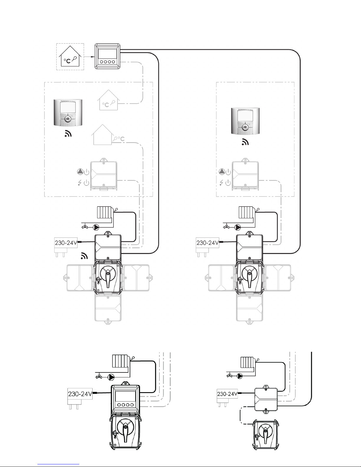
Room control
This gives the most effi cient and easiest control
function in a single family dwelling or premises with
uniform heating needs. Easy installation/operation
and optimum heating economy. Save up to 24%.
All of the settings for R are described on
pages 8-14.
With Room and Outdoor sensor
(see also in menu 7.3)
ROr in a family house or premises with uniform
heating needs. Higher heating comfort is achieved
with outdoor sensor-controlled maximum and
minimum limits.
ROo for regulation in multi-occupancy buildings.
The outdoor sensor normally controls the heating
according to the set control curve. The room
sensor prevents unnecessary overheating.
All of the settings for ROr are described on
pages 22-29.
All of the settings for ROo are described on
pages 30-37.
Supply fl ow control
To maintain the supply fl ow temperature constant.
All of the settings for S are described on
pages 16-21.
Outdoor control
For control in multi-occupancy buildings.
The outdoor sensor control the heating according
to the set control curve.
All of the settings for O are described on
pages 38-44.
5 different control options
EC Home is easy to optimise to the needs of your building.
R ROr/ROo
S
O
Overview
Overview
4
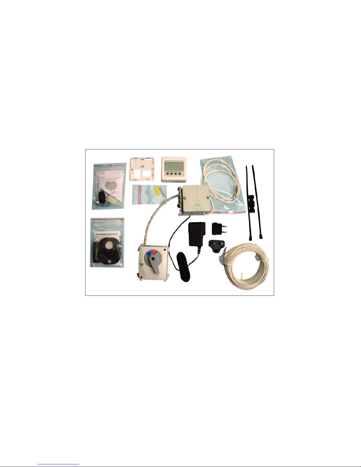
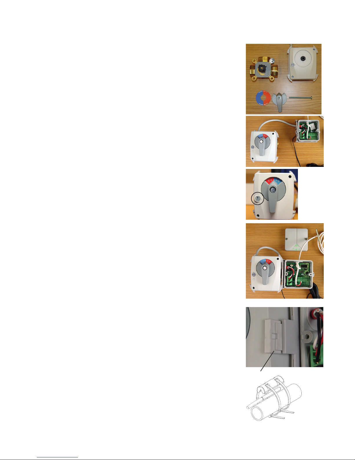
2. Delivery scope and extras (Photo 1)
1. Mixing valve motor, 24 V DC, 0-10 V, 90°, 10 Nm (connected to CC when delivered)
2. Connection centre (CC, with bracket for fi tting motor. The click lock is inside the CC on delivery (photo 2, overleaf)
3. Power supply 24 V DC (connected to the CC on delivery). With universal adapters EU/UK, 5 m cable.
4. Room sensor/control panel (CP) with installation kit for wall fi tting.
5. Flow sensor (connected to CC on delivery)
6. Installation kit for supply pipe sensor
7. Installation kit M6-NRETV, for motor on mixing valves type Termoventiler or similar
8. Installation kit M6-NRE6, for motor on mixing valve type Esbe VRG/VRB
9. 4 conductor cable, for room sensor/control panel
Overview
Overview
Abbreviations found in the text
CC = Connection centre
CP = Control panel
R = Room sensor control
O = Outdoor sensor control
ROr = Room sensor control with Outdoor sensor curve as max limiter
ROo = Outdoor sensor control with Room sensor as max limiter
S – Supply pipe sensor
1
9
8
7
6
5
4
3
2
1
5
Start Guide
3 Start Guide
NB! When using wireless room sensors, several steps are factory-set.
3.1 Fitting the motor to a mixing valve
Fit the motor to the mixing valve according to the instructions on the respective
installation kit (example shown in photos 1 and 2). Which installation kit is to be used
depends on the mixing valve, see the table and instructions in the installation kit.
Fit the plate (blue/red) for the mixing valve’s position indicator on the motor and fi x the
handle according to photo 3. NB! The motor is always delivered in the centre position and the handle only fi ts in the position that the motor is in. Insert and tighten the
screw in the centre of the motor.
Turn the motor to manual position (photo 3). NB: The handle must only be turned. If
the handle is depressed it may stick in the manual position.
Check that the mixing valve’s working area agrees with the position of the handle.
3.2 Installation of the CC
Install the CC with the motor frame bracket as shown in photo 4. NB! The bracket
can be located on either side of the motor and is pressed into place from behind. The
click lock is pressed into the slot until it says “Click” (photo 5). You can use e.g. a small
screwdriver to remove the click lock.
The click lock is loose inside the CC on delivery when the CP is not fi tted to the CC. If
not, it is in the cardboard box.
The CC can also be fi tted separately, e.g. on a wall. The box size is adapted for exterior fi tting on a 70 mm electrical box (e.g. wall socket).
3.3 Installing the supply sensor
Attach the sensor with the enclosed installation kit on the supply pipe (photo 6) as
close to the mixing valve as possible. Ensure that there is good contact. Insulate.
4
5
3
2
1
6
6
3.4 Cabling
Installing the 4 conductor cable:
Lay the whole cable between the CC and the CP before connecting to the respective units.
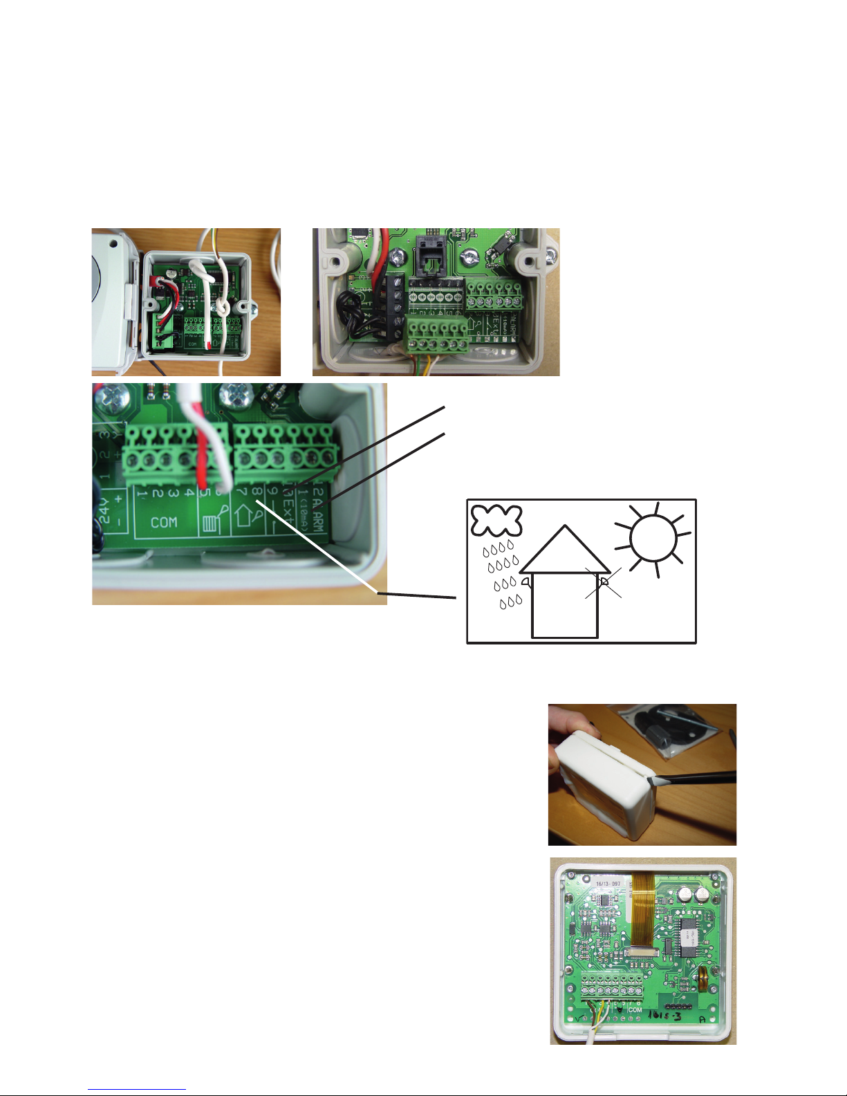
3.5 Connection of the CC
Insert the cable through the cable entry. We recommend that you knot the cable as a cable grip (photo 7).
The terminal block can be removed (photo 8) and is pushed into place on the stud after the cables are connected. Connect the
4-way multi-cable to the CC’s terminals 1-4. NB! The colour combination on the CC terminal block must be repeated when
connecting to the CP.
Photo 9 shows the CC’s various terminal blocks and their function with numbers and symbols.
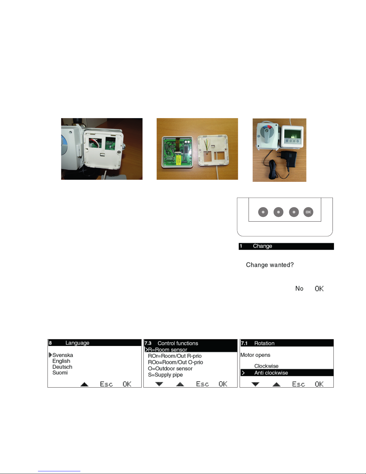
3.6 Connecting the CP
The CP is delivered with the wall fi tting/adapter loose. The CP can later be removed
simply with a screwdriver according to photo 11.
Connect the 4-way multi-cable to the CC’s terminals 1-4, as shown in photo 12.
NB! The same colour combination on the plinths as in the CC.
Do not forget to pull the cable through the wall fi tting.
The CP is then pushed in place on the bottom plate with the click lock.
Insert the lower edge fi rst, then press in the upper part.
Start Guide
Start Guide
7
12
11
8
9
10
Outdoor sensor (Extra)
Plinth 7-8
Terminals 9-10: Incoming from
external control.
Terminals 11-12: Outgoing Alarm
signal.
NB! Polarity! Terminal 11 = ”+”.
7
Start Guide
Start Guide
Using the CP
One press on any of the buttons starts the display. The second press on any button
opens the fi rst available menu.
The buttons’ function is then displayed above the respective buttons. Button 1 =
Move down/right or reduce value
Button 2 = Move up/left or increase value
Button 3 = Return/escape
Button 4 = OK/activate menu
None of the values can be changed “by mistake”. In all of the modes
where it is possible to change a value, you will be prompted whether you are sure you
want to make the change before the value is actually changed.
Basic settings on fi rst start-up
At the fi rst start-up, after the fi rst press on OK, you will be guided through the quick start process (see photos below), fi rst
System 1 and then System 2 (if System 2 is connected):
Initiation of wireless room sensor is only shown if the antenna is connected. See separate instruction.
When using two systems, a common menu is shown as fi rst picture. See pages 45-46.
Other basic settings
The maximum limit is set from 0-90 °C. Factory setting is 60 °C.
The setting is made in menu 7.4.
The minimum limit is set from 0-60 °C. Factory setting is 10 °C.
The setting is made in menu 7.4.
For more advanced settings, such as setting of night reduction etc. - see the relevant chapters for the control function you have
selected.
1324
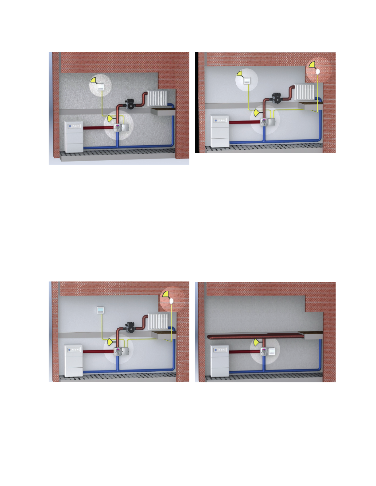
3.7 Installing the CP or separate room sensor
The CP can be fi tted on the CC or on the wall using the enclosed installation kit (plug and screw).
In its standard design, the CP has an integrated temperature sensor that is used as the room sensor. The position of the CP is
therefore decisive for correct operation when using the room sensor function.
The CP should be located centrally in the house, in a hall, stairway or similar space which is linked to as much of the rest of the
house as possible. Avoid rooms with a lot of supplementary heat sources, such as a kitchen, south-facing living room or upstairs
in a two storey house. Position the sensor away from direct sunlight. Avoid placing on an external wall or near an external door.
Make sure the sensor is not positioned closer than 1 m from the nearest radiator and around 1.5 m from the fl oor.
When using passive room sensor, wireless room sensor, only outdoor sensor or only supply sensor, the
position of the CP is unimportant.
For installation on the CC, see photo 13. The cover screws are then used to fi x the CP wall fi tting directly to the CC. The multicable is always pulled through the wall fi tting as shown in photo 14. Photo 15 shows installation with the CP on the CC.
1413
15
8
Current room
temperature
Control function
R = Room sensor
6. USER GUIDE - R
In this section, each menu is described in detail.
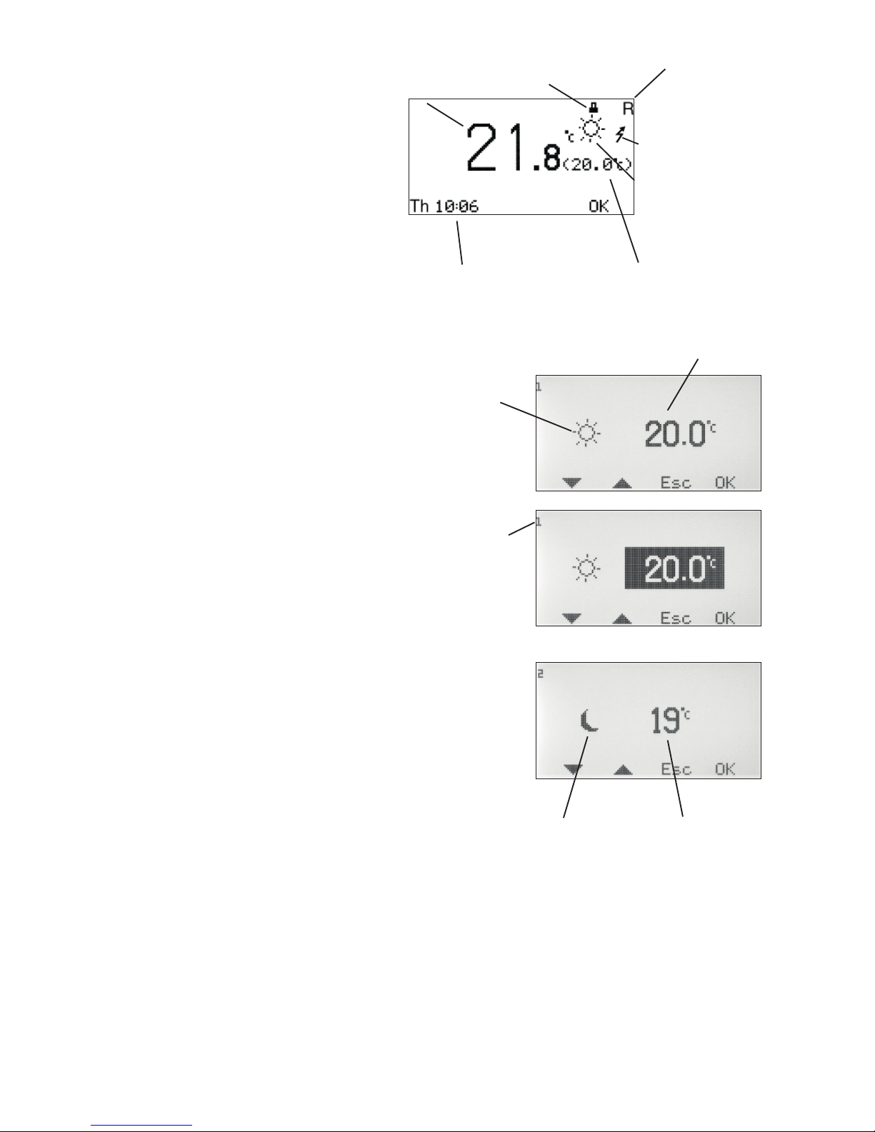
Menu 0 – Basic menu
The basic menu only shows basic information.
The actual room temperature, the room temperature set point, locking (if the Security code has
been activated) and time and day of the week (if the
clock function has been activated).
In menu 7.5.4 you can select that only the set point should
be displayed.
It also shows which control mode is applying and which control function has been selected.
Menus 1 and 2 – Adjustment of
set point for room sensor
Depending on which control mode has been selected in menu
3, a sun or a moon is displayed before the set point.
The selectable value is from 5-30°C for day, and 1-30°C for
night, with 0,1°C intervals.
In order to access the night setting, the clock or
night temperature must be activated in menu 3.
HINT: By activating locking of display and/
or menu changes in menus 7.5.2 and 7.5.3,
you can limit access by unauthorised persons to view/change settings.
Current day and time.
NOTE! Only displayed
if the clock function is
used.
Temperature set point
Set point setting
Shows that
you are
changing day
temperature.
Set point setting
Shows that you
are changing night
temperature.
The fi gure in the
left corner tells
you which menu
you are in.
USER GUIDE – R
USER GUIDE – R
The padlock shows
that the menu lock
has been activated.
A fl ashing lightning is
shown when Additional
heating is active.
Control mode
9
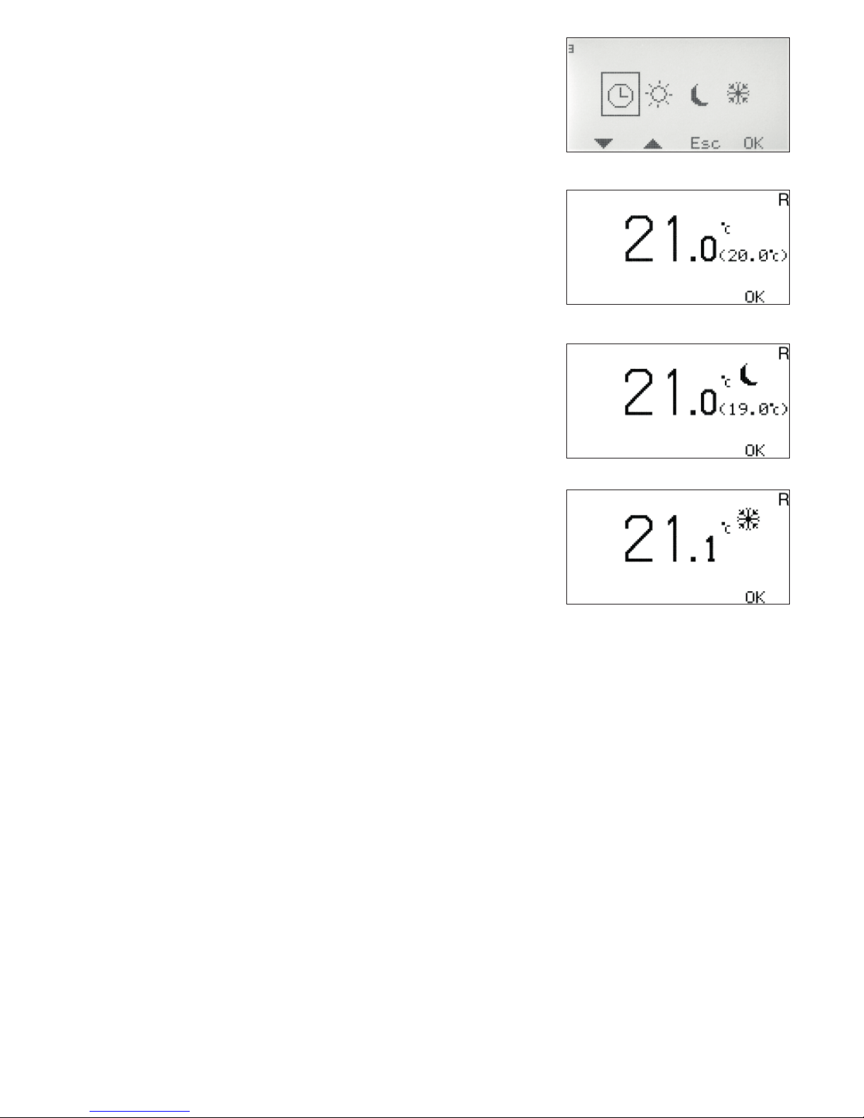
Menu 3 – Setting control mode
In this menu you can activate the clock function, constant day, constant night or if you want to shut down the control.
Depending on what is selected in menu 3, the basic menu, menu 0,
will display different information.
Current day and time are displayed in menu 0 only when the clock
function is activated.
Sun = Day temperature active. Menu 0 only displays the sun when
the clock is active.
Moon = Night temperature active.
Snowfl ake = Shut down. The set point for the Supply fl ow tempe-
rature is set automatically at 10°C.
USER GUIDE – R
USER GUIDE – R
10
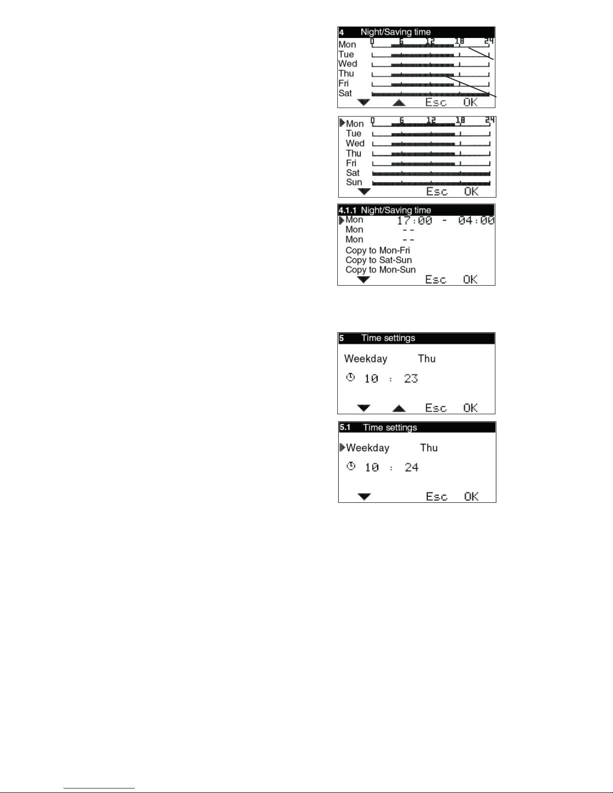
Menu 4 – Time settings for
Night/Saving time
NOTE! Only displayed if the clock function is activated.
Night temperature times can be set for every day of the week.
Use the up and down arrows to go to the day you want to set. The arrow
along the left edge shows which day has been selected. Press OK again to
activate the selected day.
4.1.1 Time setting
3 different times can be set for each day. The settable range is 00-24.
NOTE! Setting 17:00 – 04:00 means that a decrease takes place from
17:00 – 00:00 and 00:00 – 04:00 for the selected day, not the following
day.
If you want the same decrease to apply to several days, you can use
“Copy to...”, to copy the decrease Monday to Friday, Saturday to Sunday,
or the entire week.
Return to menu 4 to view the selected settings.
Menu 5 – Time settings
NOTE! Only displayed if the clock function is activated.
Setting of current weekday and time. Hours and minutes are set individually.
Night
temperature
active
Day
temperature
active
USER GUIDE – R
USER GUIDE – R
11
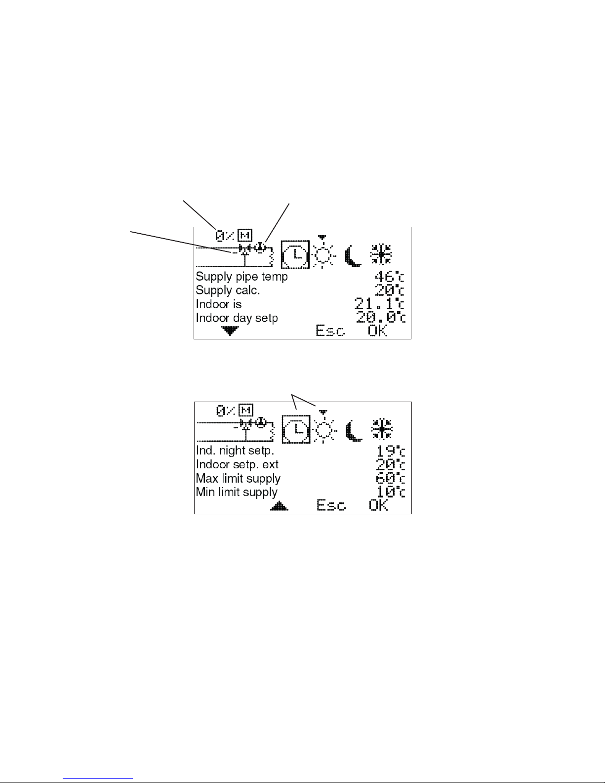
Menu 6 - List
Shows all relevant temperatures and settings as below.
Values that are displayed change back and forth automatically.
Click OK to stop the changes and then the up and down arrows to browse
them.
NOTE!
The set point for the room temperature day/night/ext is
shown, even when the clock function or external setting are
not used.
0% shows that the
motor is completely
closed. 100% means
fully open. +/- indicates
opening/closing
Shows that the circulation
pump is active. If the pump
stop function is not being
used, the symbol turns
constantly.
Control mode
Clock = day/night function activated
Arrow over the sun shows the day temperature is currently active.
USER GUIDE – R
USER GUIDE – R
12
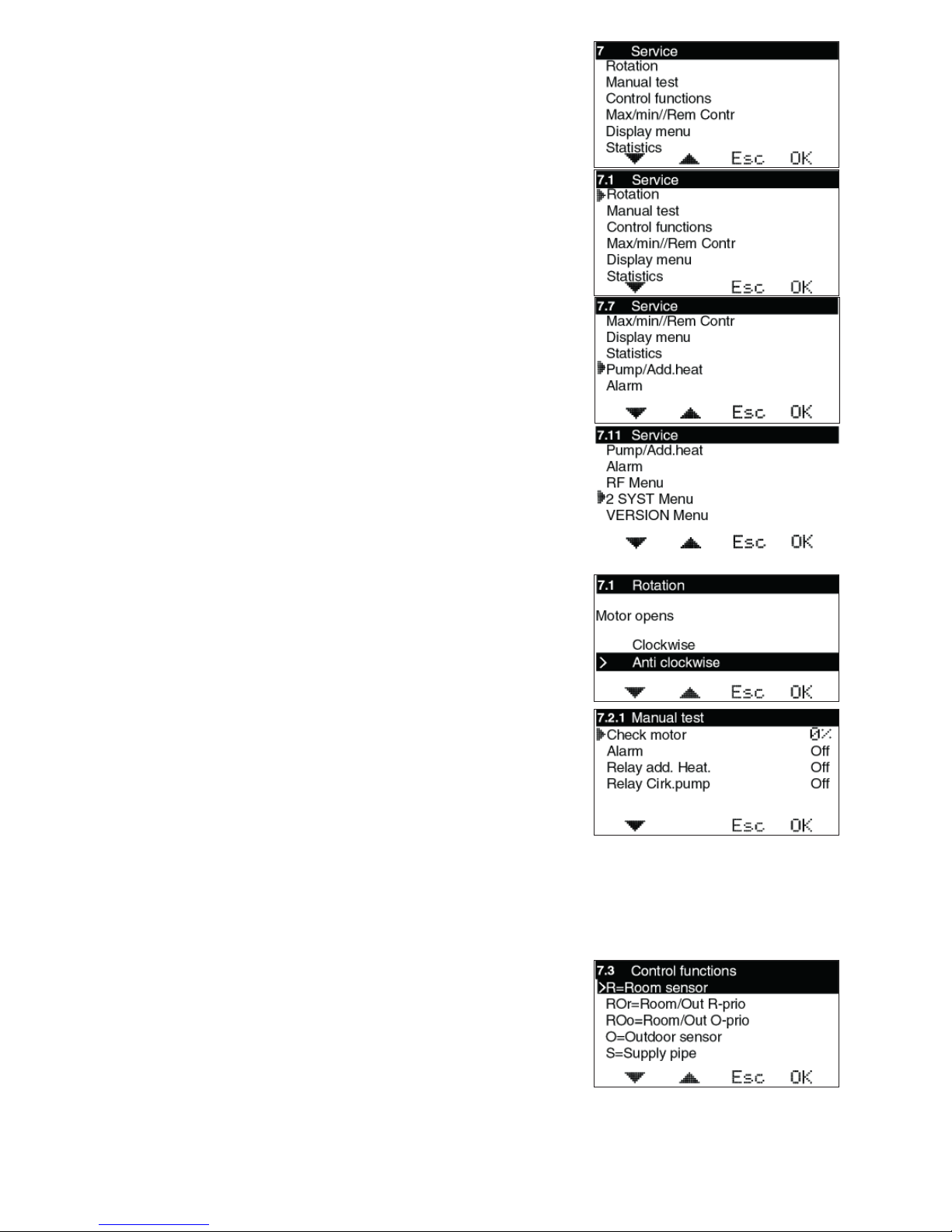
Menu 7 - Service
The following options are available in this menu. The arrow along the left edge shows
which menu has been selected.
7.1 Rotation – Setting for the direction of rotation – clockwise or anti-clockwise
opening.
7.2 Manual test – Manual running of the mixing valve motor.
7.3 Control functions – Selection of control function; Room sensor (R),
Room+Outdoor sensor with Room priority (ROr), Outdoor+Room sensor with Outdoor
priority (ROo), Outdoor sensor (O), and only Supply fl ow sensor (S).
7.4 Max/Min//Rem Contr – Setting of max. and min. limits for supply temperature and desired room temperature under external control.
7.5 Display Menu - Setting the menus to be shown/changed.
7.6 Statistics – Shows the history for temperatures for the various sensors.
7.7 Pump/Add.heat – Used in combination with the relay box to start/stop the
circulation pump, heating booster etc. Only shown if relay box is connected
7.8 Alarm – Used to send an alarm, e.g. an SMS if the GSM control is connected, if
a specifi c sensor temperature is exceeded or not reached.
7.10 RF Menu – Used to activate wireless room sensor (WL)
7.11 2 SYST Menu – Used to activate System 2.
7.12 VERSION Menu – Shows software version for the CP.
7.1 Rotation
To select clockwise or anticlockwise motor opening.
7.2 Manual test
Used to test various connected functions manually.
Motor check – Press OK to open or close the motor using the up and down
arrows. If the motor goes the wrong way, the direction of rotation must be changed in
menu 7.1.
Alarm – Press OK to change on or off using the up and down arrows.
Used to send a signal if something is wrong. The setting is carried out in menu 7.8.
In the case of an alarm, connection is made on terminal block 11-12, marked “Alarm”
in the CC.
Relay add. Heat. – Press OK to change on or off using the up and down arrows.
Used with the relay box to start/stop booster heating. Also see 7.7.1.
Relay Circ.pump – Press OK to change on or off using the up and down arrows.
Used with the relay box to start/stop the circulation pump. Also see 7.7.1.
7.3 Control functions
Description of the various control functions can be found in “List”, page 3.
Outdoor sensor is not included in the basic package.
USER GUIDE – R
USER GUIDE – R
13
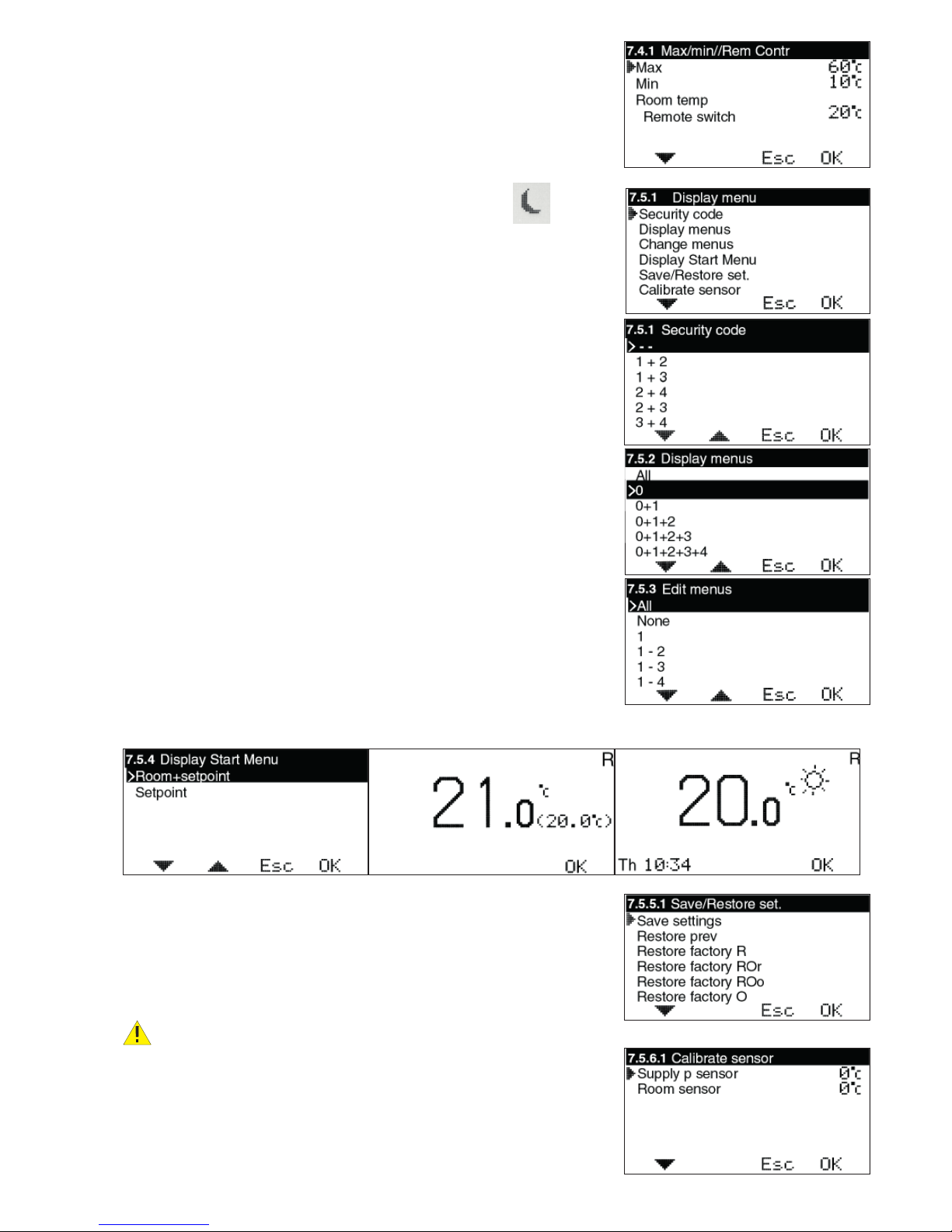
7.4 Max/Min//Rem Contr
Max = Maximum permitted supply fl ow temperature. Settable from 0-90°C.
Min = Minimum permitted supply temperature. Especially suitable for underfl oor
heating systems. Settable from 0-60°C.
Room temp Remote switch = Desired room temperature when the external contact has closed, e.g. via GSM-control. Settable 10-30°C. Remote switch is
connected to terminals 9-10, marked “Ext” in the CC.
When External contact is closed, the Moon+E is shown in menu 0:
7.5 Display Menu
7.5.1 Security code
This is where you can specify if you want to be able to lock EC Home’s buttons
and menus. This occurs when 20 seconds have passed and no buttons have been
pressed. The code that has been chosen is used to unlock them. When the Security code is used, the selected buttons must be pressed and held for 5 seconds to
enable unlocking.
Menus 7.5.2 and 7.5.3 are displayed only when the Security
code has been selected. When the menus are locked, a padlock
is shown in menu 0.
7.5.2 Display menus
This is where you can select which menus are shown when the Security code is
activated.
7.5.3 Edit menus
This is where you can select which menus can be edited when the Security code is
activated.
7.5.4 Display Start Menu
This is where you can select whether Menu 0, which shows the temperature,
shows the current temperature + the set point or just the set point.
7.5.5 Save/Restore set.
Here, you can select “Save settings” to save the settings you have made.
In this way, you can use “Restore prev” to go back to the correct settings if you,
or anyone else, has changed the settings by mistake.
“Restore factory R/ROr/ROo/O/S” can be used to return all of the basic settings
to the factory settings.
”Restore factory” resets EVERYTHING to factory settings. No settings is
saved. When using two systems, both systems are reset to factory.
7.5.6 Calibrate sensor
This is where you can select to adjust the value of the supply fl ow sensor or room
sensor if you do not think that the value shown on EC Home is correct. Settable
from +5 to -5°C.
USER GUIDE – R
USER GUIDE – R
E

14
7.6 Statistics
This is where you see what the Supply pipe temperature, Room temperature and Outdoor temperature (if outdoor sensor is being used) have been over the last few hours.
The supply sensor shows the last 200 minutes, every second minute. The values for the
other sensors change much more slowly, and here you can see the last 200 hours, every
second hour.
Use the up and down arrows to mark the sensor you want to view the statistics for, and
press OK to view a temperature graph. You then use the left or right arrows to move the
cursor at the bottom right of the graph to read the value for a specifi c minute or hour.
HINT: By pressing on the right arrow straight away you can jump to the oldest value.
Click Esc to return to the Statistics menu.
7.7 Pump/Add.heat
This is where you set whether you will use the function for start/stop of the circulation
pump to the heating system, booster heating etc. NOTE! An extra box is required.
Pump stop Room sensor cont On/Off – If this function is activated the pump
will stop when the control motor has been fully closed for 20 minutes. Thereafter, the
pump is run for 5 minutes at noon every day
NOTE! The time is retrieved from the set time. If not time is set, noon is regarded as
being 12 hours after system start-up. When the room sensor wants heating, the pump
restarts immediately.
V-pos.Add.heat – If you want booster heating to start when the valve is in a specifi c
position, you can set that here. 0 means that the motor is completely closed, 100 that
the motor is completely open.
Time delay heat – How long it must take after the above valve position is achieved
before the booster heating starts. Settable 0–254 min, >254 = ∞ (off).
Time delay vent – How long it must take from the booster heating starts until the
motor opens more. Settable 0–254 min.
Valve exercise. On/Off - When the Pump Stop is activated, you can select exercise of the mixing valve. The pump is then stopped and the motor runs until it is completely open and back again to closed position before it is controlled normally again. This
takes place at 12 noon every Monday.
7.8 Alarm switch
Is used to send an alarm, e.g. SMS, if a specifi c temperature is exceeded/not reached
by a sensor. NOTE! Requires special equipment.
In the case of an alarm, connection is made on terminal block 11-12, marked “Alarm” in
the CC. Terminal 11 = ”+”.
Settable values are 0-90°C.
Alarms can be transmitted for: Sensor fault, Low room temperature, High supply temperature or Low supply temperature.
Menu 8 - Language
USER GUIDE – R
USER GUIDE – R
 Loading...