

Page 1
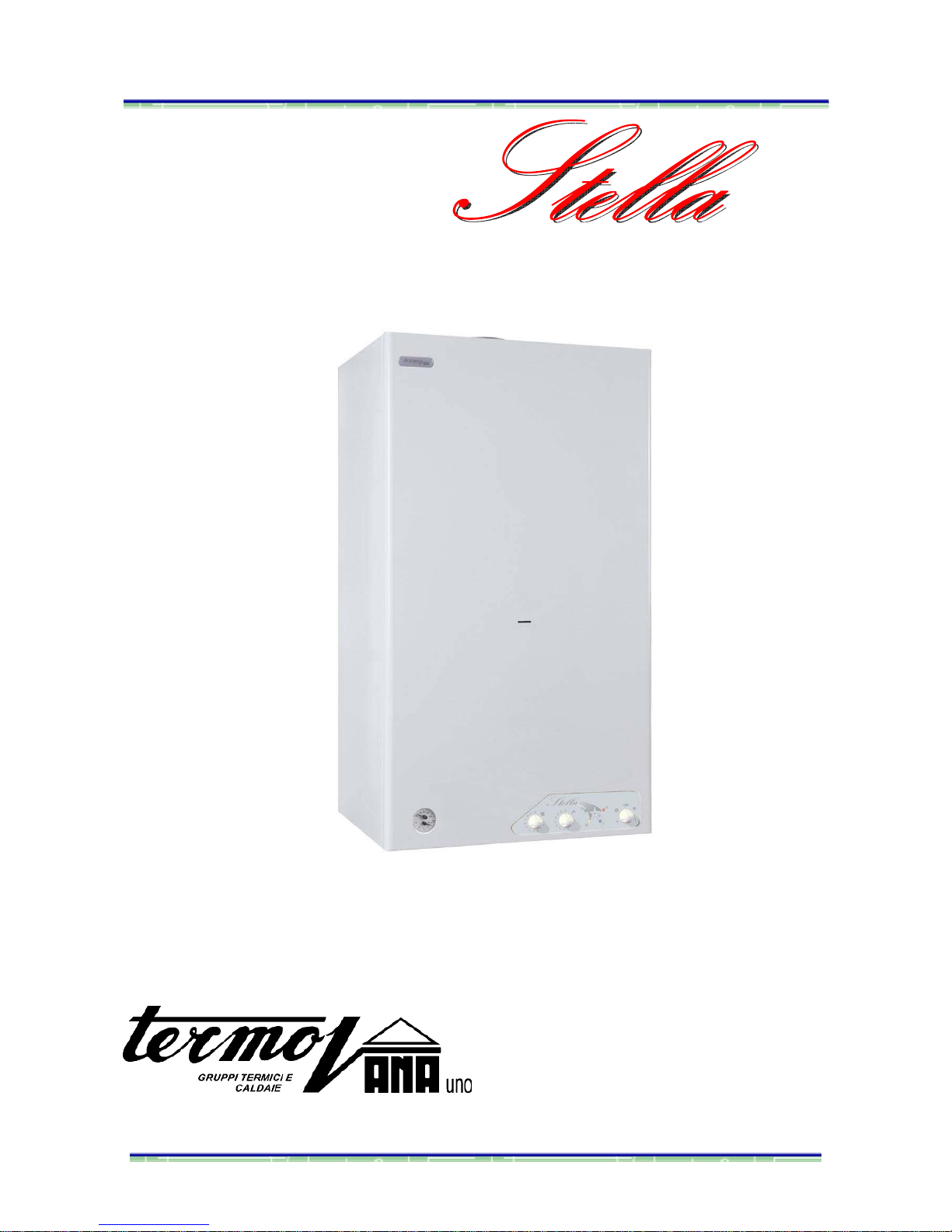
W
W
W
a
a
a
l
l
l
l
l
l
-
-
-
m
m
m
o
o
o
u
u
u
n
n
n
t
t
t
e
e
e
d
d
d
t
t
t
y
y
y
p
p
p
e
e
e
C
C
C
s
s
s
e
e
e
a
a
a
l
l
l
e
e
e
d
d
d
-
-
-
c
c
c
h
h
h
a
a
a
m
m
m
b
b
b
e
e
e
r
r
r
c
c
c
o
o
o
n
n
n
d
d
d
e
e
e
n
n
n
s
s
s
i
i
i
n
n
n
g
g
g
b
b
b
o
o
o
i
i
i
l
l
l
e
e
e
r
r
r
I
I
I
n
n
n
s
s
s
t
t
t
a
a
a
l
l
l
l
l
l
a
a
a
t
t
t
i
i
i
o
o
o
n
n
n
,
,
,
M
M
M
a
a
a
i
i
i
n
n
n
t
t
t
e
e
e
n
n
n
a
a
a
n
n
n
c
c
c
e
e
e
a
a
a
n
n
n
d
d
d
U
U
U
s
s
s
e
e
e
r
r
r
s
s
s
’
’
’
M
M
M
a
a
a
n
n
n
u
u
u
a
a
a
l
l
l
Page 2

1
Table of Contents page
Overview ……………………………………………………………………………..2
General warnings ………………………………………………………...…………….2
Safety Measures …………………………………………………………………………..…….3,4
Installation…………………………………..……………………………………... 5
Pre-installation warnings ……………………………………………………………………… 5
Location ……………………………………………………………………………………………5
Dimensions and templates ……………………………………………………………………….6
Minimum clearances …………………………………………………………………………….. 6
Gas connections …………………………………………………………………………………. 7
Water connections……………………………………………………………………………… 8,9
Flue exhaust connections…………………………………………………………………. 9,10,11
Feed cable and room thermostat connections……………………………………………. 12,13
Electrical layout …………………………………………………………….…………….……… 14
Boiler inspection ………………………………………………………..…………………………15
Preparing the boiler for initial ignition ……………………………………………………….16,17
Initial ignition and further checks …………………………………………………………….18,19
Operation adjustment and gas flow regulation ………………………………………………...20
Boiler Protection Systems ………………………………………………………………………21
Maintenance …………………………………………………………………………………...22
General concepts …………………………………………………………………………………22
Combustion analysis ……………………………………………………………………………..22
Procedure for emptying the installation ………………………………………………………23
Troubleshooting…………………………………………………………………………………...24
Users’ Manual ………………………………………………………………………………..25
General warnings …………………………………………………………………………………25
General safety rules ………………………………………………………………………………26
Getting to know your boiler ………………………………………………………………………27
Boiler Set-up ………………………………………………………………………………………28
Maintenance ……………………………………………………………………………………….29
Technical Details …………………………………………………………………………….30
The following pictograms are shown in some parts of this manual:
Failure to observe this warning could cause serious and even lethal injuries
to people.
Failure to observe this warning could cause serious damage to the
appliance, objects, plants and animals.
Page 3
2
OVERVIEW
This booklet is an essential part of the product. The user must keep this booklet in good condition. It
must always accompany the boiler when it is transferred to another owner or user and/or installed in
other premises.
The instructions and warnings relating to installation, use and maintenance safety contained in this
booklet should be read carefully.
General warnings
The technical instructions contained in this booklet are intended to help installers install the boiler
appropriately.
This appliance produces hot water for domestic use.
It must be connected to a heating system and a hot water circuit compatible with the functions
and power of the boiler.
It is forbidden to use this appliance in any manner other than its intended purpose. The
manufacturer cannot be held responsible for any damage resulting from misuse, improper or
illogical use of the appliance or due to failure to follow the instructions contained in this booklet.
Following provisions of Act No 46 dated 05/03/1990, only a technician with an appropriate installation license
can install the heating appliances. This technician must give the user the DECLARATION OF
CONFORMITY once the appliance is installed.
Installation, maintenance and any other intervention must comply with the regulations in force and
the instructions provided by the manufacturer. The manufacturer cannot be held responsible for any
damage to people, animals or objects resulting from incorrect installation of the appliance. While
carrying out initial ignition, maintenance, combustion analyses or any other technical operation, only
a qualified technician must be present near the boiler or in the room where it is installed.
The boiler is cardboard-packed; once the packaging is open, ensure that the appliance is
complete and not damaged. Return to manufacturer if the appliance does not fulfil these
requisites. Keep dangerous packing components (staples, plastic bags, expanded polystyrene,
etc.) out of the reach of children.
Turn off the appliance in the case of failure and/ or malfunctioning, close the gas inlet cock and
do not try to repair it. Contact a qualified technician.
Before carrying out any intervention on the boiler, cut off the power supply by setting the externally
fitted switch to “OFF”.
Only a qualified technician must carry out repairs when needed. Use original spare parts only.
Failure to observe this warning could cause serious damage to the appliance for which the
manufacturer cannot be held responsible.
Turn off the appliance to operate or carry out maintenance of the structure near the flue exhaust
connections or devices, and their accessories. Once the interventions are finished a qualified
technician must check that the pipes and the devices work correctly.
Turn off the boiler and set the externally fitted switch to “OFF” to clean the external components.
Use a piece of damp cloth and soapy water to clean the appliance. Do not use abrasive
detergents, pesticides or toxic products.
To guarantee the correct operation of the boiler, a qualified technician must service it once a year
and carry out the combustion analysis every two years. He must also complete the boiler logbook in
accordance with the corresponding regulations.
Page 4
3
Safety Measures
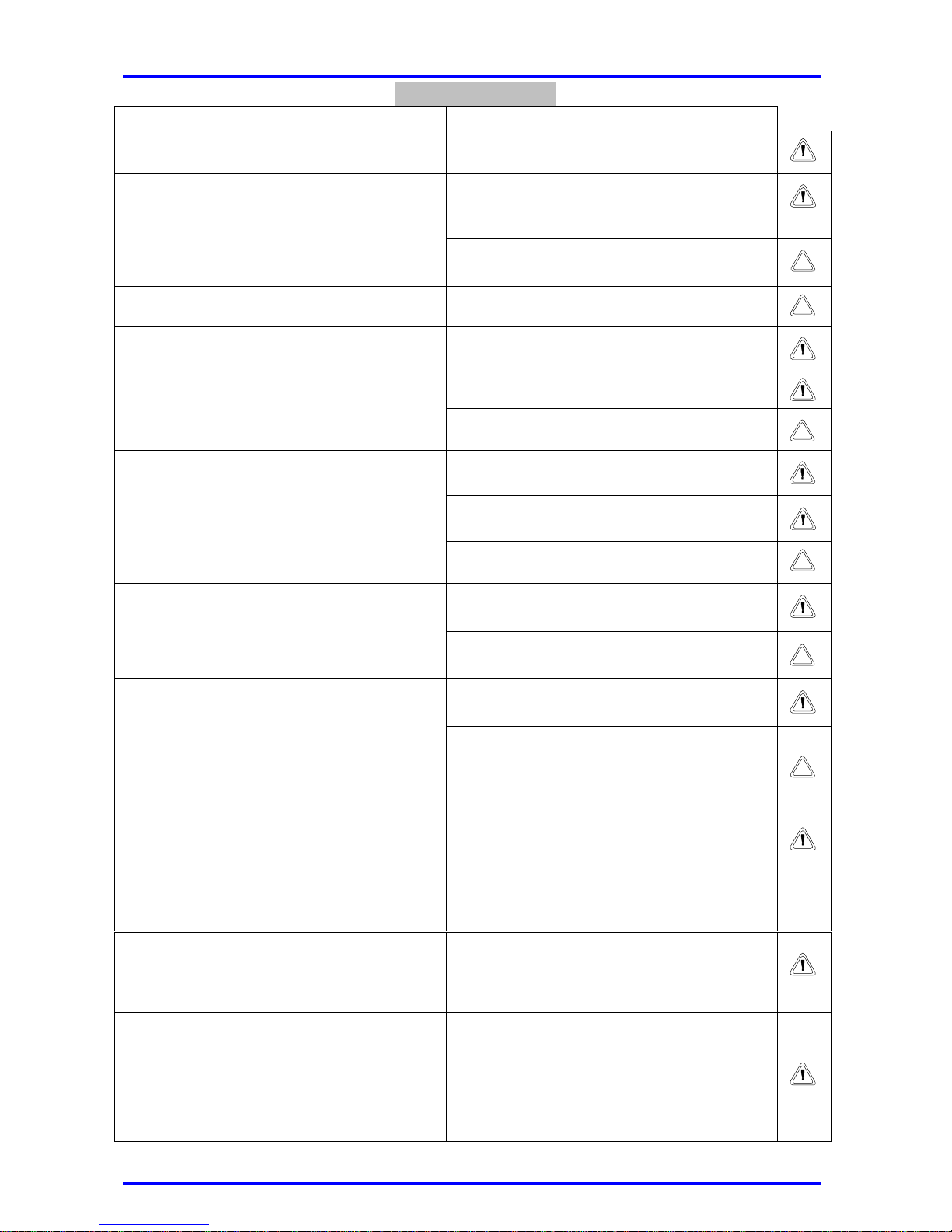
STANDARD RISK
The appliance must be installed on a vibration-free
solid wall.
Noise during operation.
Electric shock when coming into contact with live
wires.
Explosion, fire or intoxication due to gas leakage
from damaged tubes.
Be careful not to damage or perforate the wall or
the existing electrical cables and pipes.
Damage to existing systems
Flooding due to leakage of liquid from damaged
tubes.
Use appropriate cable section to carry out the
electrical connections.
Fire risk due to overheating caused by electrical
current flowing through undersized cables.
Electric shock when coming into contact with live
wires.
Explosion, fire or intoxication due to gas leakage
from damaged tubes.
Protect pipes and connection cables so that they
cannot be damaged
Flooding due to leakage of liquid from damaged
tubes.
Electric shock when coming into contact with live
wires that are not properly installed.
Explosion, fire or intoxication due to incorrect
ventilation of discharge fume pipes.
Make sure that the area where the appliance is
installed and the systems to which it is connected
comply with the regulations in force
Damage to the appliance due to malfunction.
Risk of personal injury from ejected splinters or
fragments, dust inhalation, impacts, cuts,
punctures and scratches.
Use adequate tools correctly (make sure that the
tools are not damaged and that the handles are
complete and correctly fixed). Secure them.
Replace them after use.
Damage to the appliance or adjacent objects due
to ejected splinters, knocks and cuts.
Risk of personal injury from ejected splinters or
fragments, dust inhalation, impacts, cuts,
punctures, scratches, noise or vibration.
Use adequate electrical equipment correctly (make
sure that the feed cable and the plug are not
damaged and that the parts with rotary and
reciprocating motions are adequately fixed). Make
sure that the feed cables do not cause an
obstruction and are correctly secured. Disconnect
and replace them after use.
Damage to the appliance or adjacent objects due
to ejected splinters, knocks and cuts.
Make sure that the rolling ladder is sturdy and
firmly set against the wall, that the steps are not
damaged or slippery, and that the ladder is fitted
with a handrail up to the top and with a protected
platform.
Risk of personal injury due to accidental falls from
a height or from the severing of limbs (doublesided ladder).
Make sure that the fall-safe ladder is sturdy and
firmly set against the wall, that the steps are not
damaged or slippery. Make sure that ladder does
not move when in use. Any operation requires the
assistance of a second person.
Risk of personal injury due to accidental falls from
a height.
Make sure that, when carrying out interventions at
a height (of at least two-metres) all safety
measures for preventing accidental falls- protection
guards surrounding the working area or personal
harnesses- have been taken. Make sure that there
are no dangerous objects in the path of a possible
fall and that the fall would be cushioned by a semirigid or soft surface.
Risk of personal injury due to accidental falls from
a height.
Page 5
4
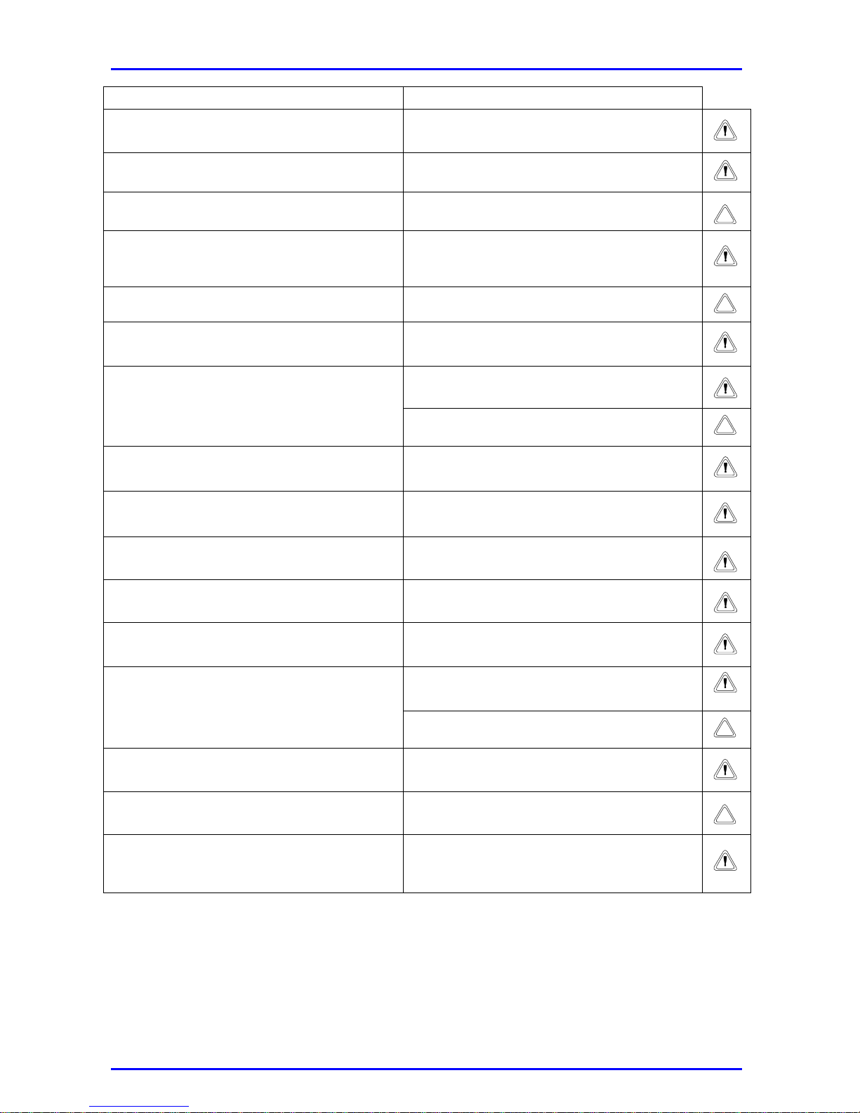
STANDARD RISK
Make sure the working area presents adequate
health conditions with respect to lighting,
ventilation and sturdiness.
Risk of personal injury from knocks, trips, etc.
Handle the appliance with proper care. Risk of personal injury from knocks, trips, etc.
Use adequate material to protect the appliance and
the zone near the working area.
Damage to the appliance or the adjacent objects
due to ejected splinters, impacts, hits or cuts.
Wear personal protection clothing and equipment
during operation.
Risk of personal injury from ejected splinters or
fragments, dust inhalation, impacts, cuts,
punctures, scratches, noise or vibration.
Handle the materials and the fixtures safely; do not
put them in piles that may collapse.
Damage to the appliance or adjacent objects due
to knocks, blows, cuts or crushing.
Avoid accidentally coming into contact with pointed
elements when carrying out interventions inside
the appliance.
Risk of personal injury from to cuts, punctures or
scratches.
Explosion, fire or intoxication due to gas leakage or
incorrect gas discharge.
Reset all safety and control functions to guarantee
their correct functioning before operating the
appliance.
Damage to the appliance or lock-out due to
inoperative safety and control functions.
Do not carry out any operation without previously
checking for gas leaks with an appropriate device.
Explosion, fire or intoxication due to gas leakage
from damaged/disconnected pipes or faulty/
disconnected components.
Do not carry out any operation without previously
checking that there are no naked flames or sparks.
Explosion or fire due to gas leakage from
damaged/disconnected pipes or faulty/
disconnected components.
Ensure that the discharge and ventilation passages
are not obstructed.
Explosion, fire or intoxication due to incorrect
ventilation or extraction of fumes.
Ensure that the flue connections do not leak. Intoxication due to incorrect flue exhaust.
Before using the boiler, empty all the components
that may contain hot water using the appropriate
vent holes.
Personal injury from burning.
Risk of personal injury if the skin or the eyes come
into contact with acid substances, or if toxic
chemicals are breathed in or ingested.
When removing scale deposits in the components
follow the indications on the safety sheet of the
appliance used, air the room, wear protective
clothing, avoid mixing different products, and
protect the appliance and the adjacent objects.
Damage to the appliance or adjacent objects due
to corrosion by acid substances.
Close tight all openings after carrying out gas
pressure readings or regulations.
Explosion, fire or intoxication due to gas leakage
from the openings that have not been closed.
Make sure that the nozzles and the burners are
compatible with the gas supply.
Damage to the appliance due to incorrect
combustion.
If you smell gas, something burning or see smoke
coming from the appliance, cut off the power
supply, close the gas inlet cock and call the
technician.
Risk of personal injury from burning, fume
inhalation and intoxication.
Page 6
5
INSTALLATION
The installation and initial ignition of the boiler must only be carried out
by qualified technicians complying with national installation regulations
in force and with any local authority and public health organisation
requirements. While carrying out initial ignition, maintenance,
combustion analyses or any other technical operation, only a qualified
technician must be present near the boiler or in the room where it is
installed.
NB: refer to the “TECHNICAL ANNEX – SPARE PARTS” for a diagram of the components of
this model.
Pre-installation warnings
This appliance heats water at a temperature below boiling point. It must be connected to a
heating system and a hot water circuit compatible with the functions and power of the
boiler (refer to technical details). Before connecting the boiler, you must:
Clean the appliance pipes carefully to remove any threading and welding
residues or dirt that may impair the correct operation of the appliance.
Check that the boiler is suitable for use with the type of gas available (read the
instructions on the packing label and the boiler data plate).
Check that the flue is not blocked or connected to any other discharge pipe,
except when the flue has been designed for other uses, complying with the
Regulations in force.
Check that the existing flue connections are adequately cleaned and free of
scale deposits as any disconnection may obstruct the passage of fumes and
result in dangerous situations.
Make sure that unsuitable flue connections are ducted.
There is risk of scale deposits and low performance of the boiler components if
the water is very hard.
Location
The appliance must be installed on a vibration-free solid
wall.
No flammable objects must be near the boiler.
Warning
Make sure that the area where the appliance is installed and
the systems to which it is connected comply with the
regulations in force
Page 7
6
This type C appliance has an environmentally friendly sealed combustion chamber and air
supply circuit.
There are no restrictions concerning ventilation conditions and room dimensions.
The installation area must satisfy the maximum temperature values so as not to
impair the correct functioning of the boiler.
The boiler has been designed to be installed on a wall and cannot be installed on a base
or on the floor.
If the boiler is built-in, the minimum clearances that guarantee access to all boiler
components must be satisfied.
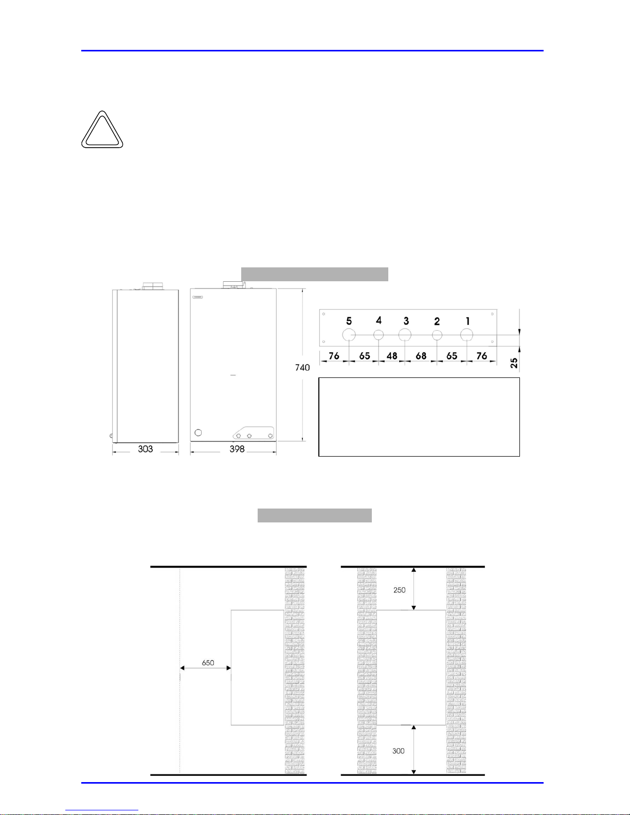
Dimensions and templates
1. Heating system return 3/4”
2. Cold water inlet ½”
3. Gas inlet 3/4”
4. Hot water outlet 1/2”
5. Heating system flow 3/4”
Minimum clearances
Comply with the minimum clearances indicated in the diagram to ensure easy and simple
maintenance operations.
Gas connections
Page 8
7
Gas connections
The boiler has been designed to be used with “2E” natural gas and “3+” LPG. Make sure
that the gas supplied is the correct type for the boiler (refer to the plate on the inner
side of the casing).
While carrying out the above mentioned operation, only authorized personnel must
be present near the boiler or in the room where it is installed.
Refer to the “Interior Boiler Inspection” section to see how to access the inside of
the boiler. .
When you need to adapt the boiler to a different gas type, proceed as follows:
Specific replacement:
• Replace the burner nozzles.
• Stick the adhesive label (supplied with the conversion kit) indicating the gas type
onto the boiler.
Adjustments;
• Unscrew screw “A” (see Page 14 ELECTRIC DIAGRAM) of pressure connection
and connect a suitable pressure gauge
• Remove the heating sensor from the input pipe using the attachment spring and set
it on the bottom of the furnace without disconnecting it
• Return the external switch to the “ON / 1” position and turn the furnace on in the
heating setting
• Remove the safety screw “C” (see Page 14 ELECTRIC DIAGRAM) and rotate the
internal plastic screw counter-clockwise a few turns until, when turning the pressure
does not decrease any further
• At this point, act on "D" until the minimum pressure is reached as indicated in the
data table for the gas used (page 30 in this booklet)
• Once the minimum pressure is adjusted, the maximum pressure is adjusted by
turning the internal plastic screw located under the safety screw, "C" until the
pressure is reached as indicated in the data table for the gas used (page 30 in this
booklet)
• Turn the external switch to the “OFF / 0” position
• Reseat the safety screw "C" paying careful attention to tighten it sufficiently in order
to avoid possible gas leaks; tighten screw "A" in the same manner
• Return the heating sensor previously set on the bottom of the furnace to the input
pipe, paying careful attention that the contact plate perfectly adheres to the pipe
and that the spring is not out of line
Check that the appliance is gastight as required by the
regulations in force.
Protect pipes and connection cables so that they cannot be
damaged.
Warning
Make sure that the nozzles and the burners are compatible
with the gas supply.
Page 9
8
The gas feed pipes must be manufactured so as to comply with the dimensions required
by the specific regulations in force and to meet the maximum boiler output. Make sure that
the gas cock is the correct size and is adequately connected.
Before installing the boiler, clean the gas pipes carefully to remove any residues
that may impair the correct operation of the appliance. It is essential to check
the gas type (methane or LPG) to be used to feed the boiler and the
corresponding rated pressure (see the “Technical Details” section); insufficient
pressure could cause a reduction in the generator capacity and could result in
discomfort for users.
Water connections
Warning
Before connecting water pipes, clean the appliance carefully to remove
any residues or dirt that may impair the correct operation of the boiler.
Make sure that the expansion tank capacity is suitable for the water
content of the boiler.
Warning
To avoid possible short circuits, install the feed cables and, if supplied, the
room thermostat at least 3 cm from the boiler connection pipes.
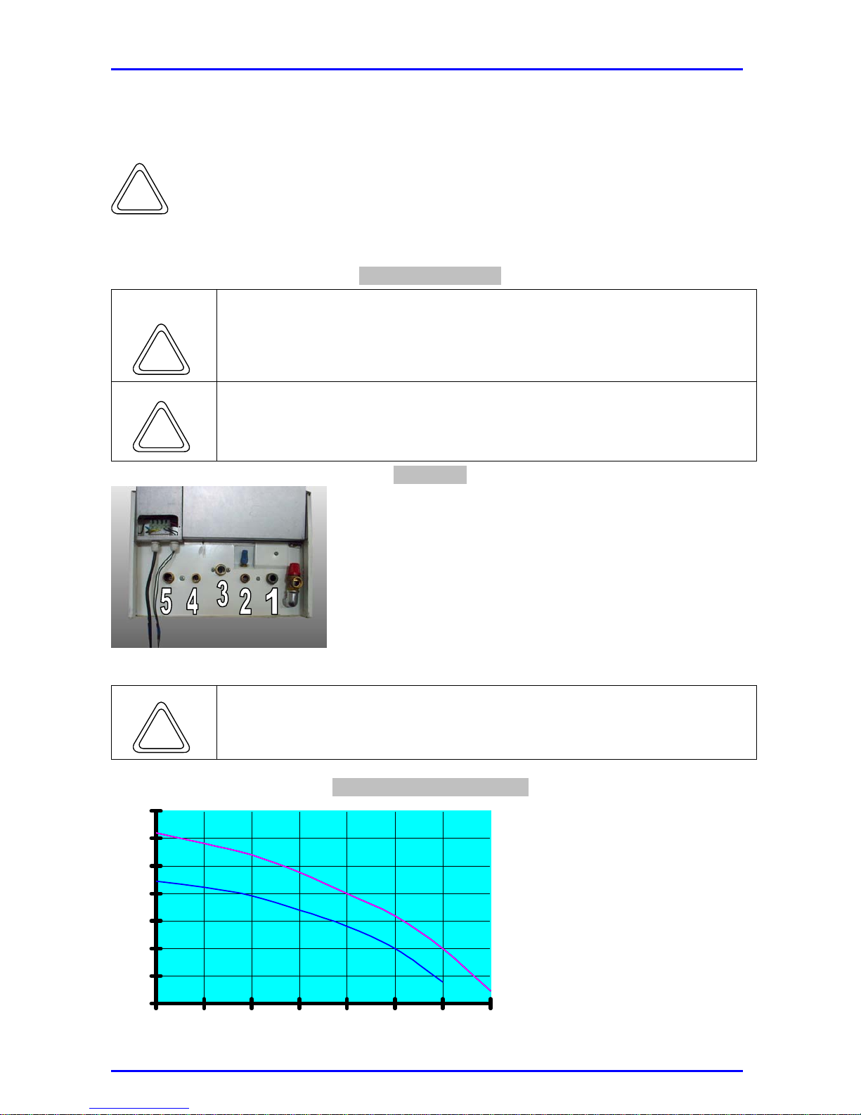
Pipe sizes
1. Heat system return 3/ 4”
2. Cold water inlet 1/ 2”
3. Gas inlet 3/ 4”
4. Hot water outlet 1/ 2”
5. Heating system flow 3/4"
Warning
Protect connection pipes so that they cannot be damaged
Residual head of circulators
1. Circulator fitted on
Stella 24 models
2. Circulator fitted on
Stella 28 models
0
1
2
3
4
5
6
7
0 0,25 0,5 0,75 1 1,25 1,5 1,75
m3/h
m
Page 10
9
The appliance is fitted with a by-pass that guarantees water flow on the exchanger for all
boiler operations.
When carrying out the discharge of the safety valve, it must be connected to a
discharge siphon which can be sight checked in order to avoid injuring people,
animals or objects. The manufacturer shall not be held responsible for such
injuries.
Flue exhaust connections
The flue exhaust connections must not come into contact with or be near
flammable materials and must not go through building structures or walls
made of flammable materials.
Warning
If a new Type C boiler is installed to replace an old one, the whole fume
extraction and flue exhaust system must also be replaced.
Ensure that the discharge and ventilation passages are not obstructed.
Warning
Ensure that the flue exhaust connections do not leak.
This sealed chamber boiler must only be installed together with a flue
exhaust device supplied by the boiler manufacturer, as required by UNI
7129 and 7131 standards.
This kit is supplied separately and according to the different installation facilities. For
further information on inlet/ flue devices, refer to the Termovana list of accessories.
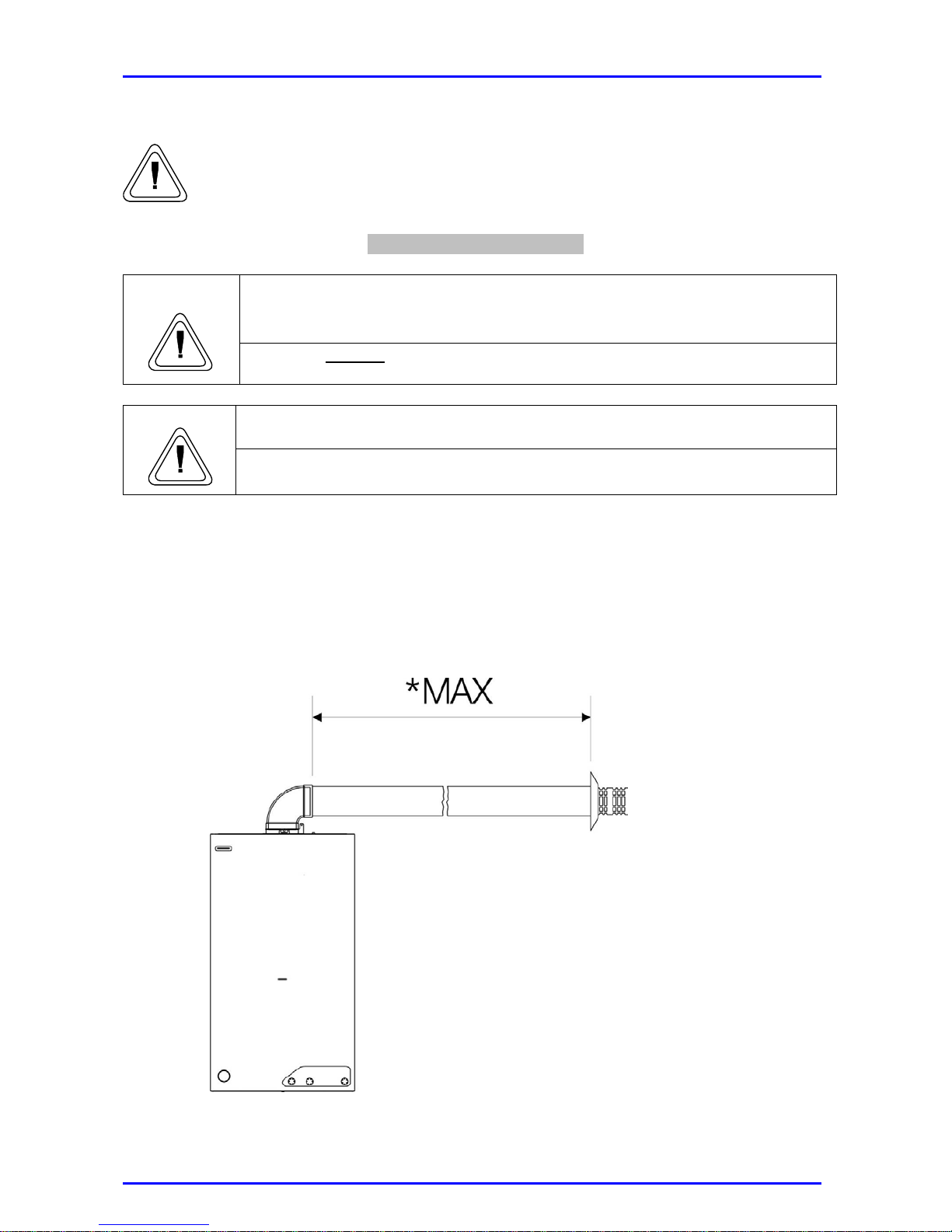
This Type C boiler has been designed to fit a coaxial flue inlet/ exhaust system (Ø 60 –
100) or a roof discharge, always coaxial, with an appropriate adapter (Ø 80 – 118).
* For a “STELLA 24” model: 4 m long max + a 90º bend
* For a “STELLA 28” model: 3 m long max. + a 90º bend
Page 11
10
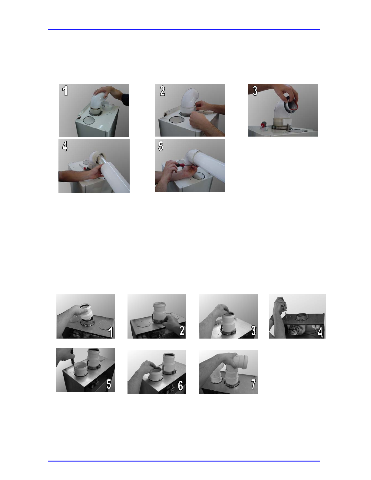
To use the coaxial system, follow these steps:
1. Connect the MF bend to the central flue spigot with the appropriate ring.
2. Use the screws to fasten the metal clamp onto the ring. .
3. Correctly position the circular silicone gasket.
4. Insert the coaxial pipe into the ring.
5. Fasten the metal clamp onto the gasket using the screws.
Remove the 39-mm fume diaphragm if a coaxial pipe over 1 m long and a bend are to be
installed.
The type C boiler can also use a Ø 80 mm twin flue discharge pipe.
To use this system, follow these steps:
1. Connect the appropriate adapter to the flue spigot.
2. Fasten the metal clamp and the neoprene rectangular gasket using the screws.
3. Correctly position the circular silicone gasket.
4. Loosen the screws to remove one of the two upper closing plates.
5. Screw down the appropriate inlet stub pipe.
6. Insert the silicone gasket.
7. Attach the kit adapted to the system to be used.
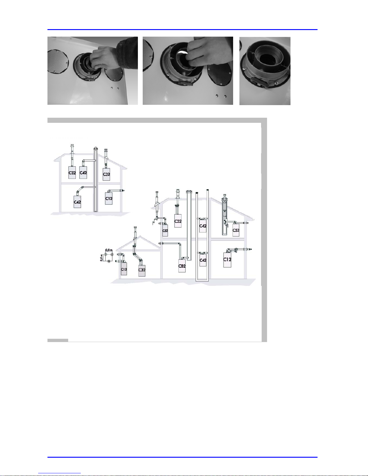
To attach or remove the diaphragm, follow these steps: in coaxial flue systems, before
attaching the bend or the adapter for roof discharge, fit the diaphragm as indicated in the
picture below and push it gently inside the aluminium flue header until it fits correctly.
For twin discharge systems, follow the same procedure described above; the diaphragm is
located upstream of the adapter.
Page 12
11
These diagrams show examples of several types of coaxial or
twin flue ducts.
For further information on discharge/ inlet accessories, refer to
the Fume Catalogue.
Types of coaxial flue systems
Types of twin flue systems
The L value of maximum perform
ance, indicated in the chart, includes the flue/ air duct and it also
includes a curve for coaxial systems.
The C52 types must comply with the following indications:
1- The inlet and flue ducts must have the same diameter (• 80 mm).
2- When attaching the curve to the inlet and/ or flue systems, the performance calculation
must include the equivalent length for each system.
3- The flue duct must protrude at least 0.5 m from the rooftop when it is located on the side
opposite to the inlet duct (this is not compulsory when the flue and the inlet ducts are on
the same side of the building).
A 39-mm diaphragm can be used with this twin system to discharge fumes up to a
distance of 8 metres. The diaphragm must be removed if the distance exceeds 8
metres and up to a maximum of 42 metres.
Remember that a small radius 90º bend is equivalent to a 1.8 m pipe run.
Page 13
12
Electric connections
Warning
The burner is continuously powered, even when the switch is in the “OFF”
position. The power supply should therefore be cut off using the externally
fitted switch before carrying out any operation on the burner.
Protect pipes and connection cables so that they cannot be
damaged.
Warning
Use appropriate cable section to carry out the electrical
connections
While carrying out the above mentioned operations, only qualified personnel
must be present near the boiler or in the room where it is installed.
To improve safety, qualified technicians must carry out a thorough control of the
electric connections. The manufacturer shall not be held responsible for damage
resulting from lack of earthing or power failures.
Ensure the system is compatible with the maximum boiler output, as indicated
on the data plate. Check that the cable sizes are the correct ones, no smaller
than 1.5 mm2
A correct and efficient earthing guarantees a safe appliance.
Important
The connections to the mains must be made by means of fixed (not
mobile) plugs and must be fitted with a double-pole switch with its
contacts at least 3mm apart.
Contact a qualified technician to replace the feed cable.
It is forbidden to use multiple sockets, extensions or plug adaptors.
It is forbidden to use the water, heating or gas system tubes to earth the
appliance.
The boiler is not protected against damage caused by lightning.
Page 14
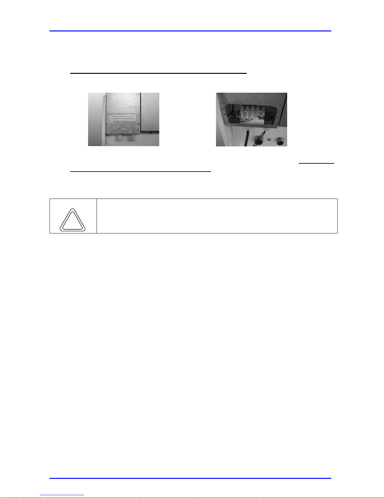
13
Feed cable and room thermostat connection
To power the boiler and connect the room thermostat, follow these steps:
1. Set the externally-fitted switch to the “OFF” position
2. Remove the lower flap to reach the terminal board.
3. Make all connections according to the indications in the diagram of the terminal
board; remember to thread the cables through the appropriate fairleads (remove the
attached flap to connect the room thermostat).
4. Fasten the fairleads and replace the flap door.
Warning
Do not connect the mains cable (230 V AC) to the room thermostat!
Doing this may damage the electronic board.
Page 15
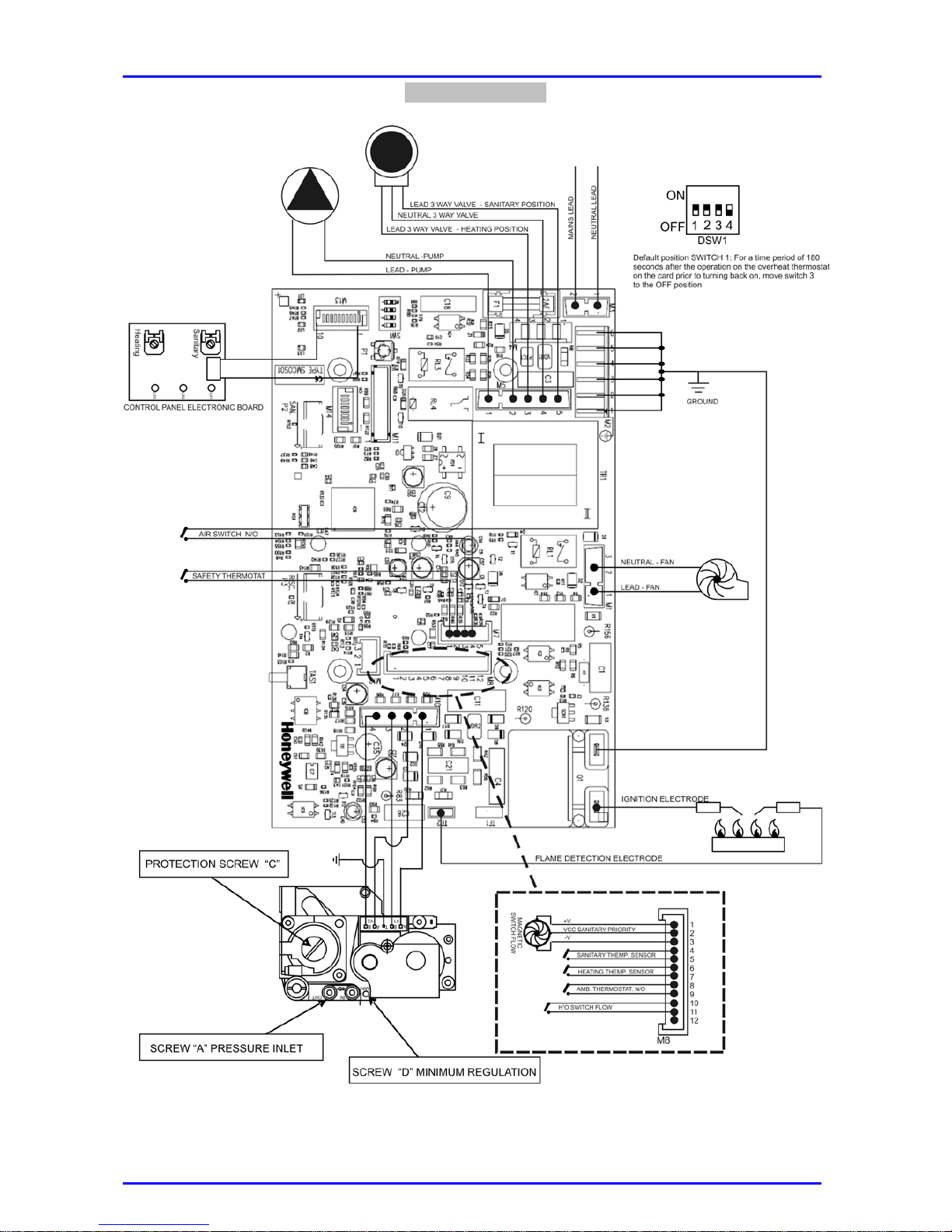
14
Electrical Layout
Screw “A” pressure inlet
Page 16
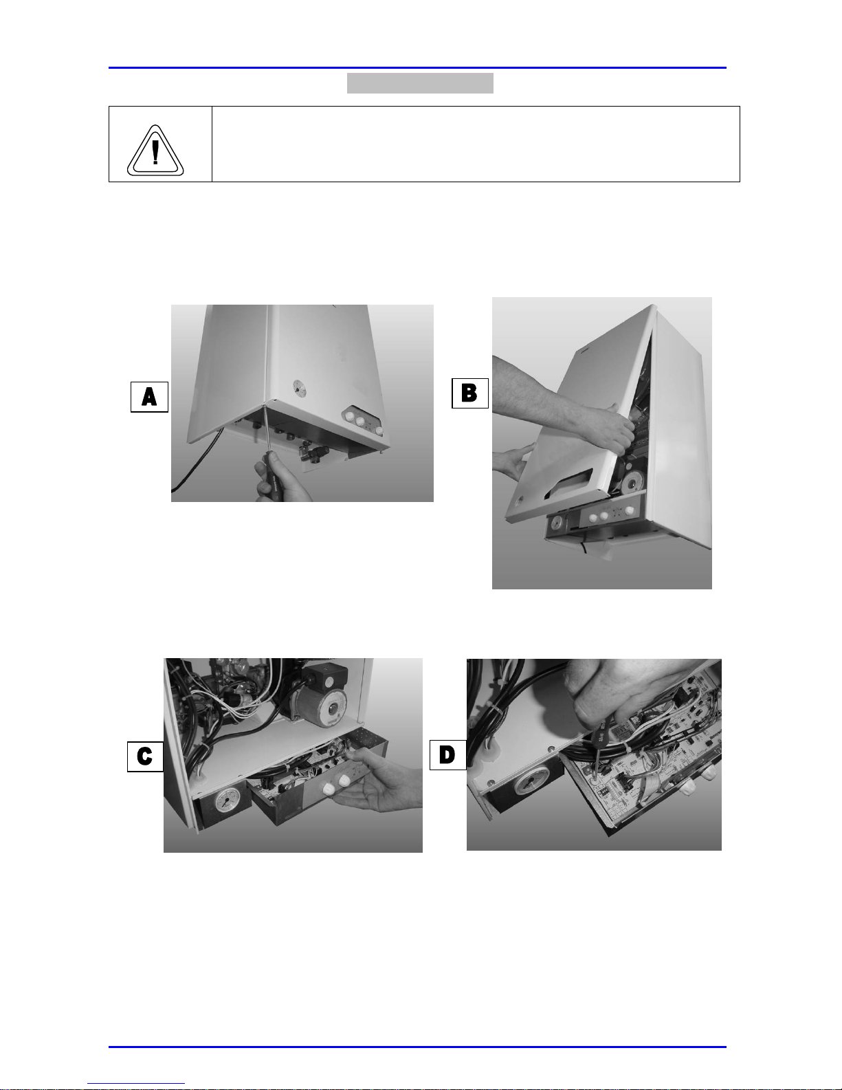
15
Boiler Inspection
Warning
The burner is continuously powered, even when the switch is in the “OFF”
position. Before carrying out any operation on the burner, make sure that
the power supply has been cut off. .
1. In order to dismount the front panel follow this procedure:
• Loosen the screws fitted in the lower part of the front panel (A);
• Release the two lateral fastening springs by pressing them with a screwdriver and
remove the front panel by pulling it out slightly and lifting it in order to release it from
the two upper draw pins (B).
2. To access the control panel
• Pull out the box “C” to have access to the setting switch (D) (this method is only to
be used when the power supply has been cut off) (pay attention to the boiler wiring,
mainly when refitting the box in its correct position for operation);
3. No other dismounting procedures are needed in order to access the control thermostat
and the safety thermostat sensors.
Page 17
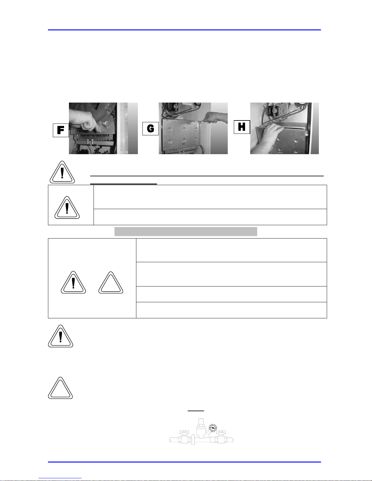
16
4. In order to access the combustion chamber:
• Dismount the expansion tank by removing the fastening screws from the mounting
brackets (F).
• Remove the screws (G) and pull out the front housing in order to separate it from the
lower drawbars (H) (carry out this operation very carefully to avoid damage to the
refractory panel installed there).
• After any maintenance and/or control operations reset all initial
adjustment settings.
Before opening the boiler, empty all the components that may contain hot
water using the appropriate vent holes.
Warning
Tighten all the vent openings before carrying out gas pressure readings or
regulation.
Preparing the boiler for initial ignition
Use the externally fitted switch to cut off the power supply to
the boiler before carrying out any operation.
To guarantee the safe use of the boiler, the equipment must
be installed by a qualified registered installer, in accordance
with the corresponding regulations.
Do not carry out any operation without previously searching
for gas leaks with an appropriate device.
Warning
Do not carry out any operation without previously checking
that there are no naked flames or sparks.
While carrying out the above mentioned operations, only qualified personnel
must be present in the room where the boiler is installed.
Before the boiler ignition and functional test, perform the following checks:
• Pre-loading of expansion tank;
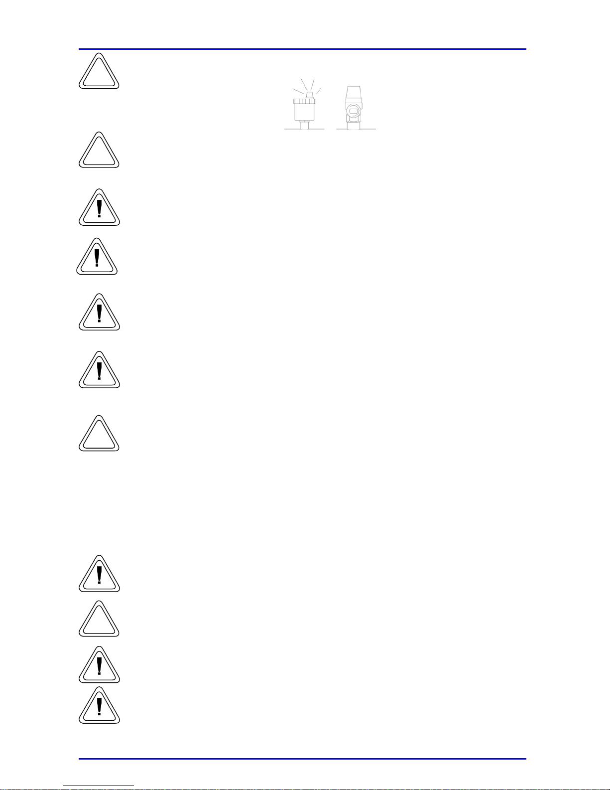
• Fill the water circuits as follows: Open the escape valve fitted in the
radiators; remove the automatic purge valve cap located on the pump;
gradually open the boiler inlet cock and close the air purge valve of the
radiators as soon as water starts to flow out. Close the inlet cock when the
water pressure gauge indicates 1 bar.
Page 18
17
• Check to see that the water circuit is perfectly sealed and that the safety
valve works properly;
• Check that the boiler is suitable for use with the type of gas available;
• Open all doors and windows; make sure that there are no naked flames or
sparks; control that the gas supply circuit is perfectly sealed (according to
the provisions in force) and that the taps are open;
• Make sure that the discharge pipes are clean and sealed;
• Check that the voltage and the mains frequency are appropriate for the
values indicated on the boiler data plate;
• Check the phase and neutral polarity of the appliance matches the electrical
mains polarity;
• Make sure that the equipment is properly earthed;
• Check the electrical connections of the external components (thermostats,
remote control, etc.), if supplied;
• When loading the system, check that the plug of the automatic air purge
valve located on the pump is loose;
• Make sure that the pump is not blocked; if so, remove the front plug to
unblock the driving shaft with a screwdriver;
• If pressure is lower than 1 bar, feed more water into the circuit.
• Make sure that the appropriate valves are open;
• Open the gas inlet cock and apply some soapy water to all connections,
including the burner connections, to check tightness; eliminate any leaks, if
present.
• Control the minimum and maximum gas pressure values at the burner, and
adjust them according to the values indicated in the chart;
• Check that the flue pressure switch functions properly (C type model);
• Make sure that there are no leaks in the fume discharge pipes;
Page 19
18
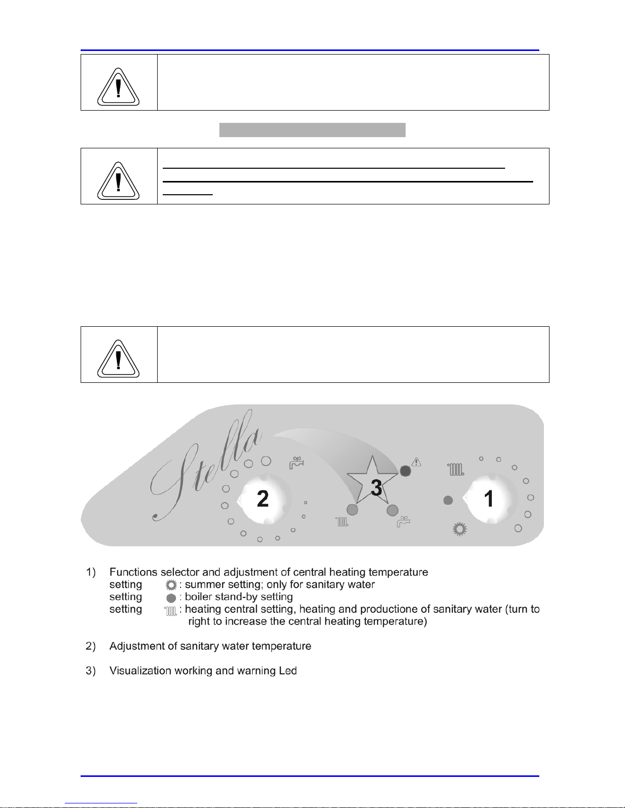
Warning
If any of the above mentioned controls yield negative results, the system
cannot be set into service.
Initial Ignition and Further Checks
Warning
While carrying out the initial ignition operations, only qualified
personnel must be present near the boiler or in the room where it is
installed.
Once the above mentioned conditions have been guaranteed, the boiler can be set into
operation. The system layout provides indications for identifying all the necessary controls
used to start up the boiler; therefore:
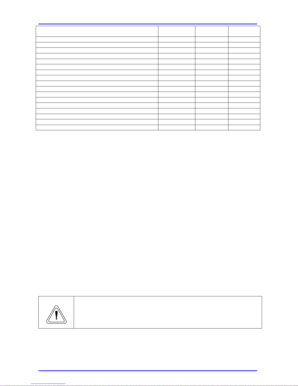
• Adjust the boiler thermostat (1) and the mains water thermostat (2) located on the
control panel:
• Power the boiler by opening the external switch:
• Set the selector (3) located on the control panel at the “winter” setting and check
that the ON pilot light (green LED) on the control panel lights up.
Warning
Important note: if the boiler is powered (the external switch is open) and
the selector (3) is set to “l” position, the electronic board and the
complementary parts are powered (the ON LED flashes slowly).
Control Panel
Page 20
19
Boiler built-in fault finding system
SANITARY
GREEN LED
RED LED
HEATING
GREEN LED
Ionic control during lock-out OFF ON OFF
Activation of safety thermostat OFF ON ON
Activation of fumes thermostat ON L ON OFF
Boiler settings error FF/ATM
(1) (1)
(1)
Activation air pressure switch ON ON OFF
Parasite flame ON L ON ON L
Activation of H2O flow switch OFF ON ON L
Failure of NTC heating system sensor OFF ON L ON L
Failure of NTC sanitary system sensor ON L ON L OFF
Activation of safety thermostat (during sanitary function) OFF ON L1 ON L
Boiler in central heating phase OFF OFF ON L
Boiler in domestic hot water cycle ON L OFF OFF
Boiler in anti-frost cycle ON L ON L 1 OFF
Stand-by ON L 1 OFF OFF
Stand-by (during heating phase) ON OFF ON
Stand-by (during summer phase) ON OFF OFF
Remote control activated ON OFF ON L0
ON L0 lit LED flashing 2 sec. ON – 0,2 sec. OFF
ON L1 lit LED flashing 5 sec. ON – 0,2 sec. OFF
ON L lit LED flashing 0,5 sec. ON – 0,5sec. OFF
ON LED on
OFF LED off
(1)
lit LED flashing of all (ON quick and 3 sec. OFF)
The appliance undergoes the ignition phase, and once firing it continues functioning until
the preset temperature is reached. Ignition and the following stops shall take place
automatically according to the preset temperature.
If the safety thermostat is activated, as indicated by the corresponding LED (see Chart No.
1), the boiler goes through a thermal safety stop. In this case, turn “1” adjustment in
stand-by position and later in heating position to restart the ignition procedure.
• Make sure that the adjustment devices function properly.
• Control the production of domestic hot water.
• Make sure that overheating thermostat functions properly.
Once the boiler has been fired and while operating under the indicated conditions,
the following stop and ignition checks must be carried out:
• Modifying the adjustment thermostat calibration.
• Regulating the room thermostat (if supplied).
If the results are successful, control the combustion (fume analyses) and the fuel flow,
checking the values indicated on the data plate.
Warning
Reset all the safety and control functions to guarantee their correct
functioning before setting the appliance to operation.
Page 21
20
Operation Adjustments
Warning
As the burner is continuously powered, even when the switch is in “OFF”
position, make sure that the power supply is cut off before carrying out any
operation on the burner.
The gas cock fitted in the boiler should also be closed.
The “STELLA” boiler allows:
• The heating circuit temperature to be adjusted using a knob (1).
• The hot water circuit temperature to be adjusted using a knob (2).
In order to gain access to the area reserved for disconnecting the accessory parts and
calibrating the boiler, follow this procedure:
• Remove the front housing.
• Pull out the control box (pay special attention to the wiring, mainly when refitting the
box).
• Now it is possible to reach electronic board and control cables to do the normal
maintenance and to replace the fuse.
Gas flow regulation
• Unscrew screw “A” (see Page 14 ELECTRIC DIAGRAM) of pressure connection
and connect a suitable pressure gauge
• Remove the heating sensor from the input pipe using the attachment spring and set
it on the bottom of the furnace without disconnecting it
• Return the external switch to the “ON / 1” position and turn the furnace on in the
heating setting
• Remove the safety screw “C” (see Page 14 ELECTRIC DIAGRAM) and rotate the
internal plastic screw counter-clockwise a few turns until, when turning the pressure
does not decrease any further
• At this point, act on "D" until the minimum pressure is reached as indicated in the
data table for the gas used (page 30 in this booklet)
• Once the minimum pressure is adjusted, the maximum pressure is adjusted by
turning the internal plastic screw located under the safety screw, "C" until the
pressure is reached as indicated in the data table for the gas used (page 30 in this
booklet)
• Turn the external switch to the “OFF / 0” position
• Reseat the safety screw "C" paying careful attention to tighten it sufficiently in order
to avoid possible gas leaks; tighten screw "A" in the same manner
• Return the heating sensor previously set on the bottom of the furnace to the input
pipe, paying careful attention that the contact plate perfectly adheres to the pipe
and that the spring is not out of line
Warning
Fully tighten all the openings used to carry out gas pressure readings or
regulation.
Page 22

21
Boiler Protection Systems
The boiler has been equipped with the following systems:
1. Lack of water: this control shuts off the boiler if the system water pressure gauge
reads a pressure lower than 0.5 bar (see Chart No. 1).
2. Overheating: this control locks the boiler out if the system temperature exceeds
100º C (see Chart No. 1).
3. Frost protection: the boiler is equipped with a system that operates the appliance at
minimum temperature output when the temperature is below 5º C. The system
remains active until the system temperature reaches ~ 30°C. This safety system is
activated both for the heating cycle and the hot water cycle, provided that the boiler
functions properly, therefore indicating that:
• The system pressure is appropriate.
• The boiler is electrically powered.
• Gas is adequately supplied.
4. Circulator protection: in order to protect the circulator and avoid lock-out, the boiler
activates the circulator for ~30 seconds every 24 hours after the last intake and/or
operation.
5. Protection of electrical shunting switch: in order to protect the valve and avoid lock-
out, the boiler activates the valve for ~30 seconds every 24 hours after the last
intake and/or operation.
6. Failure of fume extraction: an appropriate protection system locks out the boiler in
the case of any failure of fume discharge (No. 1)
7. Emergency stop: at the beginning of every firing cycle, the board carries out a
series of internal controls on the actuators; in the case of any malfunction, the boiler
shuts off until the cause of the malfunction is eliminated.
Page 23
22
Maintenance
General Concepts
Warning
Maintenance is to be carried out according to the provisions of the
regulations in force. This is essential in order to guarantee the safety,
proper use and duration of the appliance.
Maintenance shall be carried out every 12 months on the basis of the
provisions of the Presidential Decree No. 551; 21/12/99, Addendum H and
the UNI 10436 standard.
Every 24 months combustion must be analysed in order to check the
boiler’s performance and contaminating emissions.
These operations should be registered in the operation and maintenance
booklet.
While carrying out the above mentioned operations, only qualified personnel
must be present in the room where the boiler is installed.
Before carrying out maintenance operations always:
• Cut off the power supply by setting the externally-fitted switch to “OFF”;
• Close the gas and the water cocks of the heating and hot water circuits.
• After any maintenance and/or control operations reset all initial
adjustment settings.
Before opening the boiler, empty all the components that may contain hot
water using the appropriate vent holes.
In order to remove scale deposits as indicated in the safety instructions of
the product used, ventilate the room and wear proper protective clothing.
Also, avoid mixing several products and protect the surrounding
equipment and objects.
Tighten all the vent openings before carrying out gas pressure readings or
regulation.
Make sure that the nozzles and the burners are suitable for the type of gas
supplied.
Warning
If you smell burning or see smoke coming out of the appliance, or if you
smell gas cut off power supply, close the gas inlet cock, open the windows
and call the servicing technician immediately.
Combustion Analysis
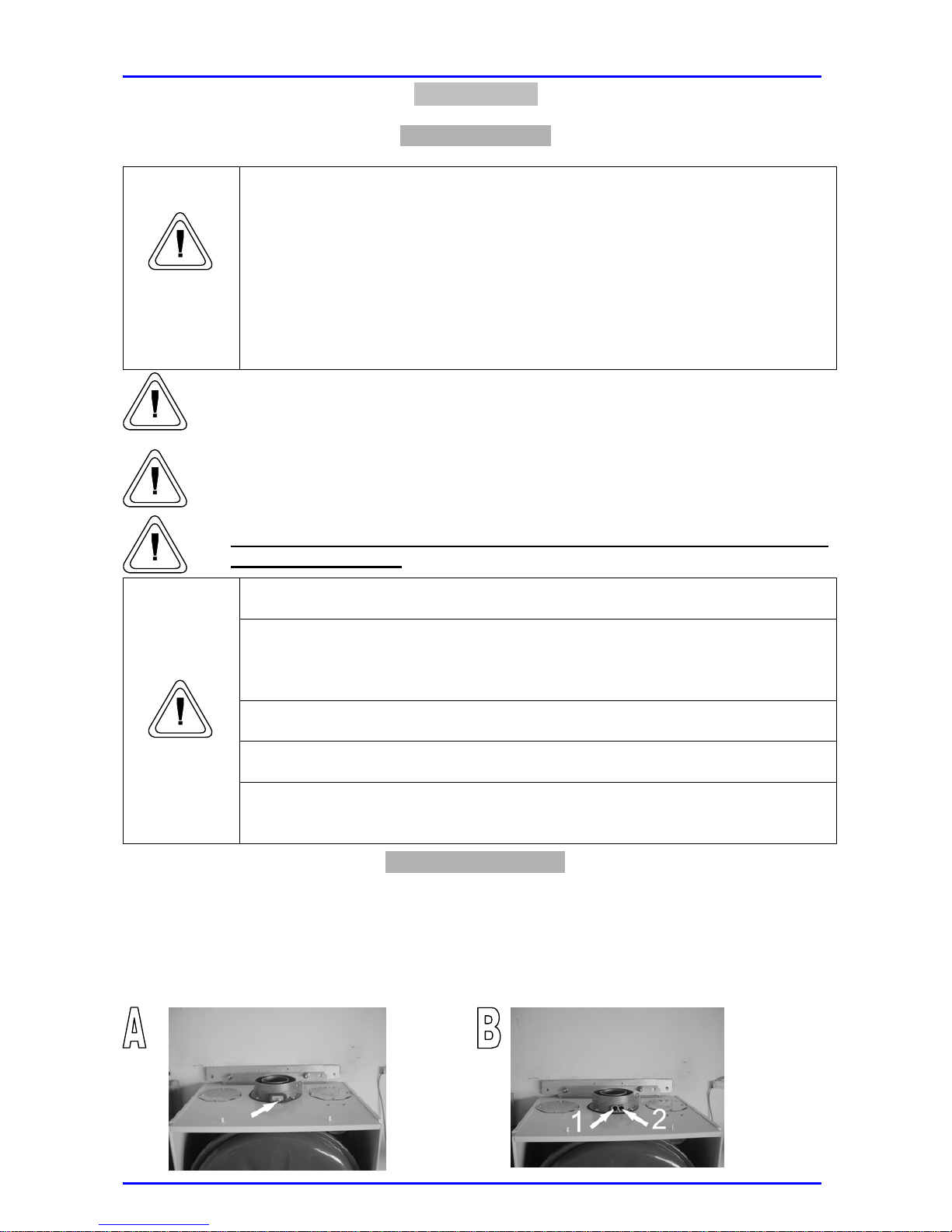
On the outside of the flue connector there are two openings used for checking the
temperature of the burnt gas and the combustion air, the concentration of O2 and CO2, etc.
To analyse combustion insert an appropriate sensor in the No. 1 opening shown in picture
A; the supply air temperature is measured in the No. 2 opening. The supply air
temperature is measured in the No. 2 opening.
Page 24
23
Procedure for emptying the installation
Heating system installation:
The heating system should not be emptied frequently since water refilling increases the
amount of scale build-up inside the boiler and the radiators. If the heating system is not
used in the winter, it may be necessary to add some anti-freeze agent to the water inside
the appliance.
To empty the system, follow these steps:
1. Turn off the boiler;
2. Manually activate the safety valve, collecting the water that pours out in a container
if the valve is not fitted with a discharge pipe union.
3. Empty the system from the lowest points (if present).
Sanitary system:
1. Close the mains water cock;
2. Open all the hot and cold water taps.
3. Empty the system from the lowest points (if present).
Before opening the boiler, empty all the components that may contain hot
water using the appropriate vent holes.
In order to remove scale deposits as indicated in the safety instructions of
the product used, ventilate the room and wear proper protective clothing.
Also, avoid mixing several products and protect the surrounding
equipment and objects.
Tighten all the vent openings before carrying out gas pressure readings or
regulation.
Make sure that the nozzles and the burners are suitable for the type of gas
supplied.
Warning
If you smell burning or see smoke coming out of the appliance, or if you
smell gas cut off power supply, close the gas inlet cock, open the windows
and call the servicing technician immediately.
Page 25
24
Page 26
25
Instruction Manual
Dear Customer,
Thank you for purchasing our boiler.
This section of the booklet has been prepared to provide you with information, warnings
and advice on the boiler installation, correct use and maintenance in order to fully
appreciate its potential.
Keep this booklet for further information.
Should you need further assistance, contact our area-servicing engineer.
Yours,
Termovana uno
Failure to observe this warning may cause serious injuries, which may even
be fatal in some cases.
Failure to observe this warning may cause serious damage to the
appliance, objects, plants and animals.
General Warning
• This manual must be kept to hand and protected against the effects of
atmospheric agents.
• Scheduled and preventive maintenance operations are essential
in order to guarantee correct and safe functioning, to avoid
excessive consumption and to reduce the emission of
contaminating agents: Maintenance must be carried out by
Qualified Personnel according to the provisions of the
regulations in force. The log book must be completed after all
servicing operations as stated by the regulations in force.
• The manufacturer shall not be contractually or non-contractually liable for
any damage to people, animals or objects, for failures caused by errors
during installation, adjustment and maintenance, misuse or incorrect or
inadequate use.
Page 27
26
General Safety Rules
Some fundamental rules must be observed when using equipment with fuel,
electrical energy or water.
During the initial ignition phase or when carrying out any servicing operation,
unskilled people must not remain in the room where the appliance is installed or
in the near vicinity.
In this case, close the gas cock, ventilate the room and contact a qualified
servicing engineer immediately.
Do not touch the appliance with wet hands and/or bare feet.
Do not clean the appliance without cutting off electricity supply.
Do not pull, disconnect or twist the outcropping electrical cables of the
appliance even if electrical power has been cut off.
Do not expose the appliance to the effects of atmospheric agents; if it is
installed outdoors, place it in a sheltered area or apply protection coating.
Do not cover and/or obstruct, and/or reduce the size of the ventilation openings
of the room where the appliance is installed, as they are essential in order to
ensure correct combustion and to avoid stagnation of toxic, explosive or
potentially hazardous gas mixtures.
If there are water leaks: cut off electrical power, close all water cocks and contact a
qualified servicing engineer immediately.
If temperature reaches 0º C, there is risk of frost. As the system features an
anti-frost device, it must remain electrically powered.
In the case of a permanent shut-off, the intervention of skilled personnel is essential
in order to ensure safety of the potentially hazardous components. In particular,
they must:
• Cut off the power supply by setting the externally-fitted switch to “OFF”;
• Close the gas inlet.
• Empty the water circuit.
Page 28
27
Getting to Know Your Boiler
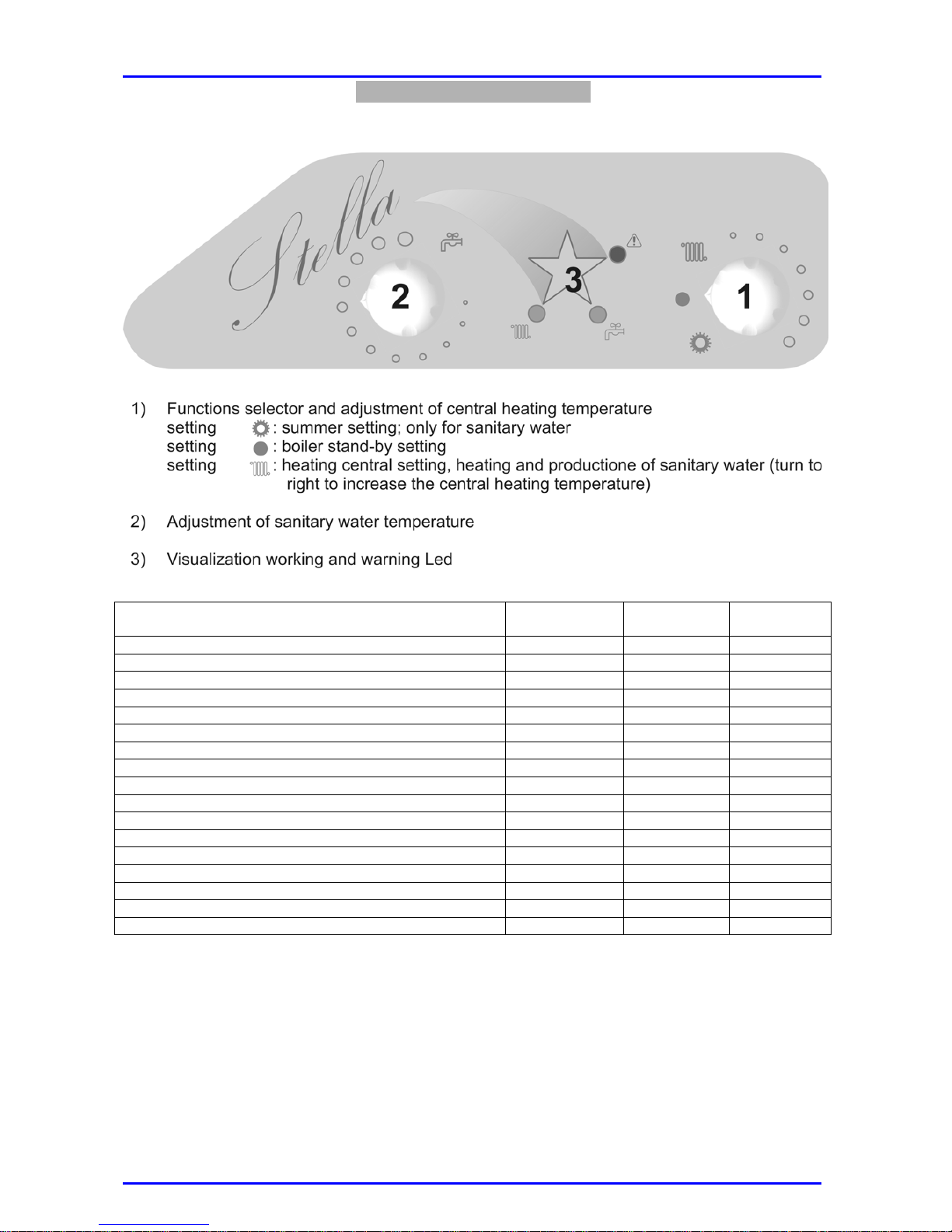
Control Panel
Boiler built-in fault finding system
SANITARY
GREEN LED
RED LED
HEATING
GREEN LED
Ionic control during lock-out OFF ON OFF
Activation of safety thermostat OFF ON ON
Activation of fumes thermostat ON L ON OFF
Boiler settings error FF/ATM
(1) (1)
(1)
Activation air pressure switch ON ON OFF
Parasite flame ON L ON ON L
Activation of H2O flow switch OFF ON ON L
Failure of NTC heating system sensor OFF ON L ON L
Failure of NTC sanitary system sensor ON L ON L OFF
Activation of safety thermostat (during sanitary function) OFF ON L1 ON L
Boiler in central heating phase OFF OFF ON L
Boiler in domestic hot water cycle ON L OFF OFF
Boiler in anti-frost cycle ON L ON L 1 OFF
Stand-by ON L 1 OFF OFF
Stand-by (during heating phase) ON OFF ON
Stand-by (during summer phase) ON OFF OFF
Remote control activated ON OFF ON L0
ON L0 lit LED flashing 2 sec. ON – 0,2 sec. OFF
ON L1 lit LED flashing 5 sec. ON – 0,2 sec. OFF
ON L lit LED flashing 0,5 sec. ON – 0,5sec. OFF
ON LED on
OFF LED off
(1)
lit LED flashing of all (ON quick and 3 sec. OFF)
Page 29
28
Boiler Set-up
The boiler may operate automatically once the service operator has carried out the initial
set-up. However, users may need to set up the appliance by themselves, without the
intervention of qualified personnel.
If this is the case, carry out these controls:
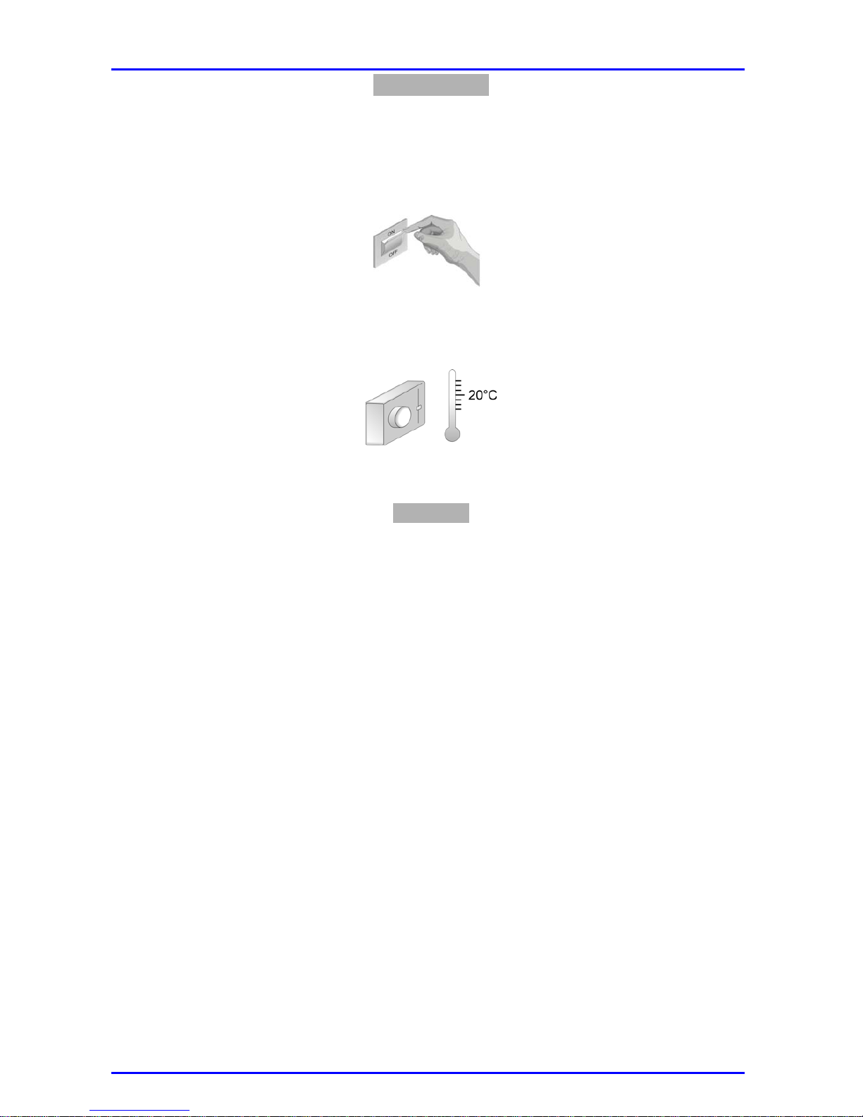
• The externally-fitted switch must be set to “ON”.
• Check the gas supply and make sure that the pipes are unobstructed.
• The water circuit must be fed and the pressure must be higher than 1 bar (see
thermohydrometer in the front part of the boiler).
• The room thermostat (if supplied) must be preset at the desired temperature.
• The boiler thermostat (1) and the domestic hot water thermostat (2) located on the
control panel must be preset at the correct temperature.
Operation
The boiler operation is very simple and clear; the boiler can be entirely controlled by
carrying out a few operations from the control panel. Once the set-up procedure has
been finished, continue as follows:
• Set the selector (3) located on the control panel at the “winter” setting to enable both the
heating system and the hot water system;
• Set the selector (3) at the “summer” setting to enable only the production of domestic
hot water.
The appliance undergoes the ignition phase, and once firing it continues
functioning until the preset temperature is reached. Ignition and the following stops
shall take place automatically according to the preset temperature.
In the case of an emergency lock-out the appliance can be restarted by slightly pressing
the push-button (4) on the control panel. If the appliance lights up correctly, the lock-out
may have occurred due to a temporary or accidental cause; in the case of repeated
stops or ignition lock-outs contact immediately the registered installer.
If the boiler built-in fault finding system detects any failure (see Chart No. 1) contact the
servicing engineer.
After each maintenance and/or service operation the service engineer must
complete the corresponding log book with the list of all the interventions carried out
on the boiler.
Page 30

29
Maintenance
Scheduled and preventive maintenance is essential to guarantee the safety, proper use
and duration of the appliance.
Maintenance reduces excessive use and contaminating emissions, and it also ensures
long-lasting product reliability.
Maintenance must be carried out by Qualified Personnel according to the
provisions of the regulations in force. The log book must be completed
after all servicing operations as stated by the regulations in force.
Page 31
30
Technical Details
Description
M/U
Stella 24 C Stella 24 CI
Stella 28
C
Stella 28
CI
Thermal Capacity
kW
24.3/11.3 24.3/11.3
Thermal power
kW
22.6/9.9 22.6/9.9
Nominal heat output
% 93.0 93.0
Heat output reduced by 30%
% 90.4 90.4
Heat loss through the flue when burner
on
% 5.2 5.2
Heat loss through the flue when burner
off
% 0.4 0.4
Consumption at nominal capacity G20
m3/
h
2.52 2.52
Consumption at nominal capacity
G30/G31
Kg/h
1.90/1.88 1.90/1.88
Flue gas temp. at nominal capacity
°C
132 132
Operation Temperature
°C
+50 / -10 +50 / -10
Heating system temperature
°C
38 – 80 38 – 80
Hot water temperature
°C
/ 35 – 55
Hot water flow ∆T=25°
°C
/ 13
Hot water flow ∆T=35°
°C
/ 9.3
Minimum hot water extraction
l
/ 2.3
Max. pressure hot water circuit
bar
/ 8
Expansion tank capacity
l
7 7
Expansion tank pre-load pressure
bar
1 1
Heating system maximum pressure
bar
3 3
G20 methane gas nominal pressure
mbar
20 20
Min. pressure at G20 methane gas
nozzles
mbar
2.6 2.6
Max. pressure at G20 methane gas
nozzles
mbar
11.3 11.3
G30 / G31 LPG nominal pressure
mbar
28-30/37 28-30/37
Min. pressure at LPG nozzles
G30 / G31
mbar
6.0/8.2 6.0/8.2
Min. pressure at LPG nozzles
G30 / G31
mbar
27.6/34.2 27.6/34.2
Supply voltage/frequency
V/Hz
230/50 230/50
Input power
W
135 135
Protection Grade of electrical system
IP
X4d
X4d
Appliance type
/
C12 C32 N
C42
C52 / C62
C12 C32 N
C42
C52 / C62
Gas category
/
II
2H 3+
II
2H 3+
Number of nozzles
No.
12 12
 Loading...