

TERMOSTROJ TermoMini Installation Manual & Users Manual
ELECTRIC BOILERS FOR CENTRAL HEATING
TermoMini
Installation manual
User guide

TMS-UT-0416-T01-0
INSTRUCTIONS FOR INSTALLATION
We reserve the right of alternations.
Contents
General ................................................................................................................................. 1
1. Introduction ....................................................................................................................... 1
1.1. Applicable documents ................................................................................................. 1
1.2. Retention of documents .............................................................................................. 1
1.3. Introduction ................................................................................................................. 2
1.4. Frost protection ........................................................................................................... 2
2. Boiler specifications ........................................................................................................... 2
2.1. Dimensions in mm ...................................................................................................... 2
2.2. Elements of TermoMini ............................................................................................... 4
3. General requirements ........................................................................................................ 5
3.1. Contents included in delivery ...................................................................................... 5
3.2. Preliminary remarks .................................................................................................... 5
3.3. Installation site ................................................................ ............................................ 5
3.3.1. Position of a boiler ................................................................................................ 5
3.3.2. Power supply ........................................................................................................ 6
3.4. System requirements .................................................................................................. 6
3.4.1. Pipe work.............................................................................................................. 6
3.4.2. Cleansing and flushing the system ....................................................................... 6
3.4.3. Filling and preparing heating system .................................................................... 7
3.4.4. Pressure relief valve ............................................................................................. 7
3.4.5. Pressure gauge .................................................................................................... 7
3.4.6. Expansion vessel .................................................................................................. 7
3.4.7. Circulating pump................................................................................................... 7
3.4.8. Air in boiler ................................ ................................................................ ........... 7
4. Boiler installation sequence ............................................................................................... 8
4.1. Transporting the appliance .......................................................................................... 8
4.2. Select position for boiler .............................................................................................. 8
4.3. Fitting the boiler hanging bracket ................................................................................ 8
4.4. Removing/fixing the front and top case ....................................................................... 9
4.5. Power supply connection ............................................................................................ 9
4.6. Connecting temperature sensors or external electrical controls .................................10
4.6.1. Accessing connection plate .................................................................................10
4.7. Filling the heating system ...........................................................................................10
5. Commissioning .................................................................................................................10
5.1. Heating system check ................................................................................................10
5.2. Preliminary electrical check ........................................................................................10
5.3. Pump .........................................................................................................................11
5.4. Working with standard control panel ..........................................................................12
5.4.1. Heating functions .................................................................................................14
5.4.2. Access to special service menu ...........................................................................15
5.4.3. Control panel “Z” – OPTION ................................................................................16
6. Maintenance ................................ ..................................................................................... 17
6.1. Periodic checking .......................................................................................................17
6.2. Cleaning.....................................................................................................................17
7. Survey of possible malfunctions and irregularities in operation .........................................18

TMS-UT-0416-T01-0
INSTRUCTIONS FOR INSTALLATION
We reserve the right of alternations.
Figures
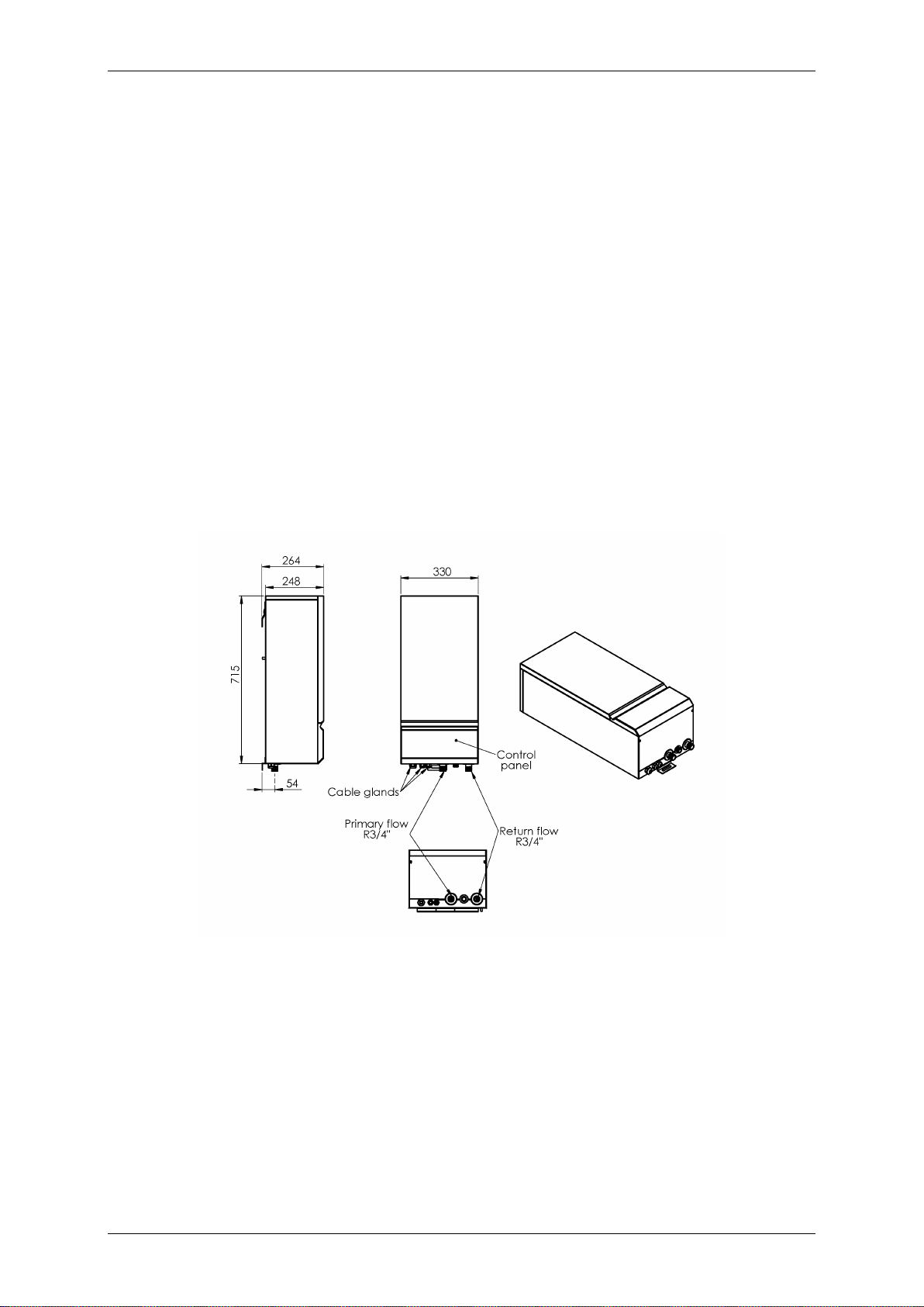
Figure 1 TermoMini dimensions, flow and return positions .................................................... 2
Figure 2. Expansion vessel and power supply characteristics ............................................... 3
Figure 3. TermoMini elements ............................................................................................... 4
Figure 4. Contents included with delivery .............................................................................. 5
Figure 5. Minimal distances for installing the boiler ................................................................ 6
Figure 6. Wall mounting ......................................................................................................... 8
Figure 7. Removing front and top case .................................................................................. 9
Figure 8 Power supply connection ......................................................................................... 9
Figure 9 Connection relay plate ............................................................................................10
Figure 10 Pump NMT PLUS 25/40 .......................................................................................11
Figure 11 Pump characteristics ............................................................................................12
Figure 12 Standard electronic control panel .........................................................................12
Figure 13 Control panel “W” - OPTION .................................................................................16
Figure 14 Hydraulic sketch for TermoMini with OPTION control panel type “Z” ....................16
Tables
Table 1. Expansion vessel characteristics ............................................................................. 3
Table 2. Power supply characteristics ................................................................................... 3
Table 3. List of TermoMini elements ...................................................................................... 4
Table 4. Table of contents included with delivery ................................................................... 5
Table 5. Pump electric and performance information ............................................................11
Table 6. Pump general information .......................................................................................11
Table 7 Possible malfunctions ..............................................................................................19

TMS-UT-0416-T01-0
Page 1
General
• Keep these instructions close to the boiler!
• The boiler must not be modified, changed or rebuilt.
• The correct settings are important for economical heating.
• The type and serial number of the boiler must be quoted whenever you contact
manufacturer or service, see the identification plate.
General safety instructions!!
- Children shall not play with the appliance.
- Cleaning and user maintenance shall not be made by children without supervision.
- Children should be supervised to ensure that they do not play with the appliance.
- Boiler is not intended for outdoor use.
Technical safety instructions!!
- Keep the water pressure between recommended limits – see chapter 3.4.3, page 7.
- Do not install boiler close the heat source (for instance, fireplace, wood stove etc…).
- Incompetent repairs can cause serious danger to users.
- Defective parts may be replaced only by the original or approved by the
manufacturer,
- Switch off main power by MCB before opening the boiler.
- Boiler has built-in frost protection. When the boiler is not in use, leave the main power
active that protection stay active.
1. Introduction
Thank you for the confidence you have shown to us by purchasing our central heating boiler.
In order to use the boiler to the utmost correctly and safely, and above all economically, read
thoroughly these instructions before continuing with installation.
A competent person, who is responsible for adhering to the existing regulations, rules and
guidelines, must install the appliances.
1.1. Applicable documents
The following additional documents are provided with the appliance:
For the owner of the system:
Instructions for use
Warranty card
For the qualified technician:
Instructions for installation
Electrical drawing for the appliance
1.2. Retention of documents
Please pass on this manual to the owner of the system. The owner should retain the
manuals so that they are available when required.
Read this document carefully before carrying out any installation,
adjustment or service and follow the instructions
TMS-UT-0416-T01-0
Page 2
1.3. Introduction
TermoMini boilers are economical central heating boilers that can be used as an
independent or additional source of heat.
TermoMini boilers offer you a possibility to reduce the power of the heater if necessary. The
power can be easily reduced through the control panel. This way it is possible to adapt the
boiler to the utmost to circumstances on the spot.
The boiler operates on a principle of rapid heating smaller water quantities, so that exploiting
energy is already 100%.
TermoMini boilers are used for radiator and floor heating. Temperature operation area is
from 20°C to 90°C. TermoMini boilers are designed in such way that in apartment-contained
central heating they can fit well with your furniture.
1.4. Frost protection
The software in control panel provides boiler frost protection. When frost protection is
controlled for entire central heating system by room thermostat, please consult room
thermostat manuals for more details.
2. Boiler specifications
2.1. Dimensions in mm
Figure 1 - TermoMini dimensions and flow and return positions

TMS-UT-0416-T01-0
Page 3
Table 1. Expansion vessel
characteristics
Volume of Expansion
Vessel
[L]
6
Maximum Expansion
Vessel Pressure
[MPa (bar)]
0,3 (3)
Filling Pressure
[MPa (bar)]
0,10 (1,0)
Maximum Pressure
In the Heating System
[MPa (bar)]
0,3 (3)
Height Of the Central
Heating System
[m]
4
Effective Capacity Of
Expansion Vessel
[L]
3,0
Adsorption Capacity
[%]
50
Maximum Amount of
Water in the System
[L]
86
Table 2. Power supply characteristics
Power
[kW]
230 V~N
400V 3N ~
50/60 Hz
3
4,5
6
9
9
12
Nominal
current
[A]
13
19,6
26,1
39,2
13,1
17,5
Fuse
current
[A]
16
25
32
50
16
25
Rated
short-
circuit
breaking
capacity Icn
(EN 60898)
[kA]
10
10
10
10
10
10
Rated
short-
circuit
breaking
capacity Icn
(IEC 947-2)
[kA]
15
15
15
15
15
15
Min.
conductor's
cross-
section
[mm2]
3x2,5
3X4
3X6
3X10
5X2,5
5x4
Fuse type
B16
B25
B32
B50
B16
B25
RCCB
switch type
[A]
25/0,03
25/0,03
40/0,03
63/0,03
25/0,03
25/0,03
Figure 2. Expansion vessel and power supply characteristics
TMS-UT-0416-T01-0
Page 4
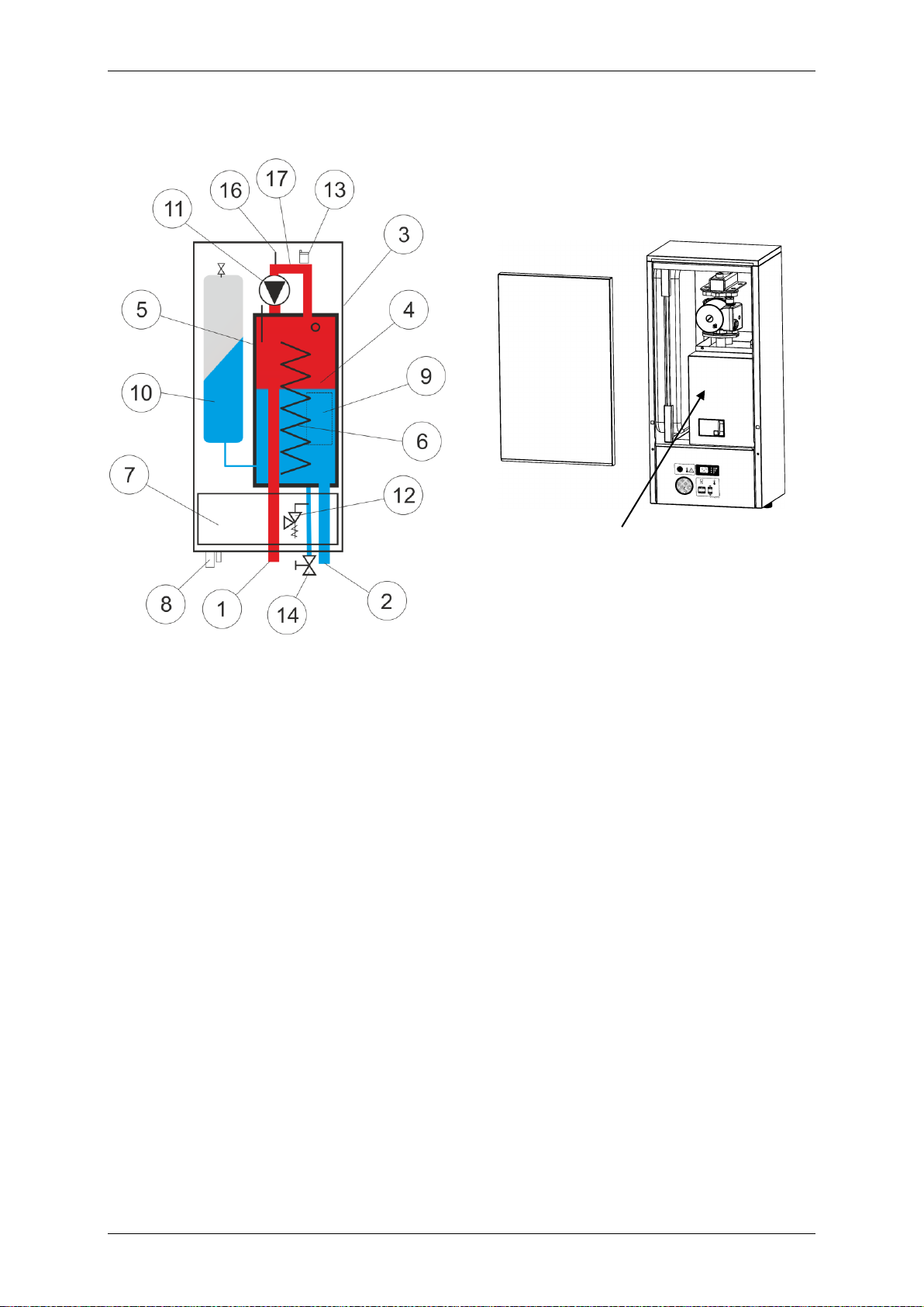
2.2. Elements of TermoMini
Power connection protection cover
Figure 3 - TermoMini elements
Table 3. List of TermoMini elements
1. Primary flow
10. Expansion vessel
2. Return flow
11. Circulation pump
3. External boiler shell
12. Pressure relief valve (0,3 MPa / 3 bar)
4. Boiler
13. Automatic air vent
5. Heat insulation
14. Charge and discharge valve
6. Electrical heaters
16. Air-indicator
7. Control panel
17. Manifold
8. Inducers for el. connections
9. RCCB switch and relays
 Loading...