

TERMOSTROJ TERMO-Blok, TERMO-Blok PTV, TERMO-Extra Instruction Manual

TRGOVINA TERMOSTROJ d.o.o. 10250 Lučko, F. Puškarića 1d
Tel/Fax +385 1 6531-008, 6531-015, 6531-016 Eurposka unija
e-mail: info@termostroj.com web: http://www.termostroj.com European Union
ELECTRIC BOILERS FOR CENTRAL HEATING
TERMO-Blok
TERMO-Extra
TERMO-Blok PTV
INSTRUCTIONS FOR USE
‘Ulaganje u budućnost’
‘Investing for the future’
Projekt sufinancira Europska unija iz Europskog fonda za regionalni razvoj.
Project is co-founded by the European Union’s Regional Development Fond.
INSTRUCTIONS FOR USE
We reserve the right of alternations

TMS-UT-0114-T03-1
INSTRUCTIONS FOR USE
We rese rve the right of al ternations

TMS-UT-0114-T03-1
Contents
1. Introduction ....................................................................................................................... 1
1.1. Applicable documents ................................................................................................. 1
1.2. Retention of documents .............................................................................................. 1
1.3. Introduction ................................................................................................................. 1
1.4. Heating curves ............................................................................................................ 1
1.4.1. Availability of heating curves................................................................................. 1
1.4.2. About heating curves ............................................................................................ 2
1.4.3. Why does the characteristic heating curve have to be set? .................................. 2
1.4.4. Corrections of the room temperature .................................................................... 2
1.4.5. Limiting the minimum and maximum temperature of the water in the boiler .......... 4
1.5. Functionality of hot domestic water ............................................................................. 4
1.5.1. Availability ............................................................................................................ 4
1.5.2. Description ........................................................................................................... 4
1.6. Frost protection ........................................................................................................... 5
1.6.1. Availability ............................................................................................................ 5
1.6.2. Domestic water ..................................................................................................... 5
1.6.3. Central heating ..................................................................................................... 5
2. Using control panels .......................................................................................................... 6
2.1. Working with standard control panel ........................................................................... 6
2.2. Working with electronic control panels (option E) ........................................................ 7
2.3. Working with electronic control panels (option C and W and Termo Blok PTV) ........... 8
2.3.1. General ................................................................................................................ 8
2.3.2. Central heating functions .....................................................................................11
2.3.3. Domestic water functions (control panel type 2)...................................................13
2.3.4. Central heating functions with heating curves disabled ........................................15
3. Maintenance .....................................................................................................................16
3.1. Periodic checking .......................................................................................................16
3.2. Cleaning.....................................................................................................................16
3.3. Central heating system ..............................................................................................16
3.4. Starting the pump manually .......................................................................................16
4. Survey of possible malfunctions and irregularities in operation .........................................18
INSTRUCTIONS FOR USE
We rese rve the right of al ternations

TMS-UT-0114-T03-1
1. Introduction
Thank you for your confidence you have shown to us by purchasing our central heating boiler.
In order to use the boiler to the utmost correctly and safely, and above all economically, read
thoroughly these instructions before continuing with installation.
The appliances must be installed by a competent person, who is responsible for adhering to
the existing regulations, rules and g u idelines.
1.1. Applicable documents
The following additional documents are provided with the appliance:
For the owner of the system:
Instructions for use
Warranty card
For the qualified technician:
Instructions for installation
Electrical drawing for the appliance
1.2. Retention of documents
Please pass on this installation manual to the owner of the system. The owner should retain the
manuals so that they are available when required.
1.3. Introduction
TERMO-Extra and TERMO-Blok are economical central heating boilers that may be used as an
independent or additional source of heat.
TERMO-Extra and TERM O-Blok boilers offer you the possibility, to reduce the po wer of a heater if
necessary. The power may be switched on when necessary automatically with the built-in step
regulator or manually with switches on the c ontrol board. In this way it is possible to ad apt t he boiler to
the utmost to circumstances on the spot.
The boiler operates on the principle of rapid heating smaller water quantities, so that exploiting of
energy is already 100%.
They are particularly suitable for heating smaller business premise, where you are short of space
(small apartm ents, efficiency apartments, represent ation offices, smaller coffee-shop s paces etc.) or
for heating larger spaces in early season when the main boiler is over dimensioned.
TERMO-Extra boilers are manufactured only with upper connecti ons. Temperature operation area is
from 20
o
C to 90 oC.
TERMO-Extra and TERMO-Blok are designed in such a way that in apartment-contained central
heating they can fit well with your furniture.
1.4. Heating curves
1.4.1. Availability of heating curves
Use of heating curves, temperature compensation, is limited to Termo Extra boilers with options C and
W, Termo Blok boilers with option C and Termo PTV boilers.
INSTRUCTIONS FOR USE
We reserve the right of alternations
page 1
TMS-UT-0114-T03-1
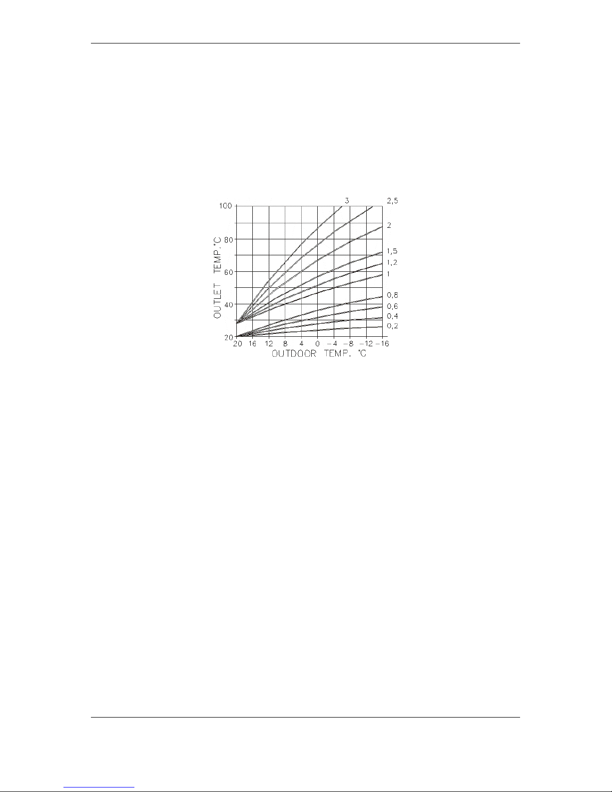
1.4.2. About Heating curves
The modern wa y of heating is based on energ y savings and automatic adjustment s to worm up the
space.
To achieve the required tem perature electric bo iler with electronic contro l panel heats the water in the
boiler automaticall y depend ing on the ex tern al tem perat ure. T here is no need to look af ter the minimal
working temperature because electric boilers do not dew and that m eans that the temper ature of the
water in the boiler is at the same time the temperature in the heating elements (for example in
radiators, convectors etc.).
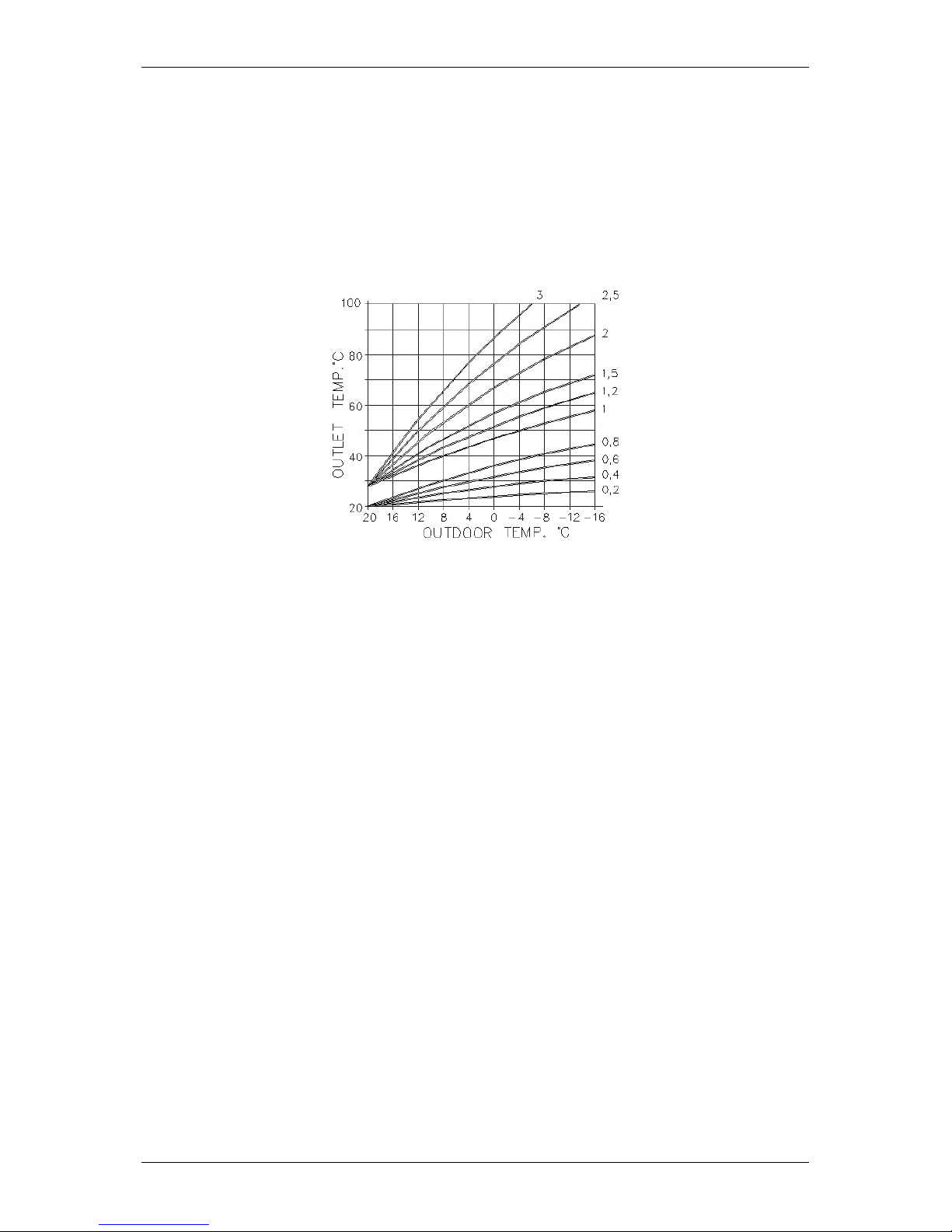
To achieve the desired room temperature, the characteristic heating curve has to be chosen
depending on the characteristics of the object and the heating system.
Factory defined curves
If the heating curve is set optimally for heating your apartment or a house, corrections will not
be necessary.
1.4.3. Why does the characteristic heating curve have to be set?
After the first settings of the heating curve an authorized person can adjust, correct that curve if
necessary.
Every heating room is bui lt up d if f er entl y. Dif f erent hea t ing el ements and heating syst ems can be used
(radiators, under floor heating or combined heating) and every building has a different thermal
insulation.
For the maximum exploitation of the heating and maximum energy savings, characteristic heating
curve has to be set using the parameter on the control panel, in a way that the chosen heating curve is
suitable for the heating system and for quality of the building.
1.4.4. Corrections of the room temperature
Based on experience, factory settings of the device are for the average insulated object and room
temperature of 22
o
C. If factory settings are not adeq uate for achieving the desired room temperat ure,
supplemental adjustments of the standard heating curves can be made.
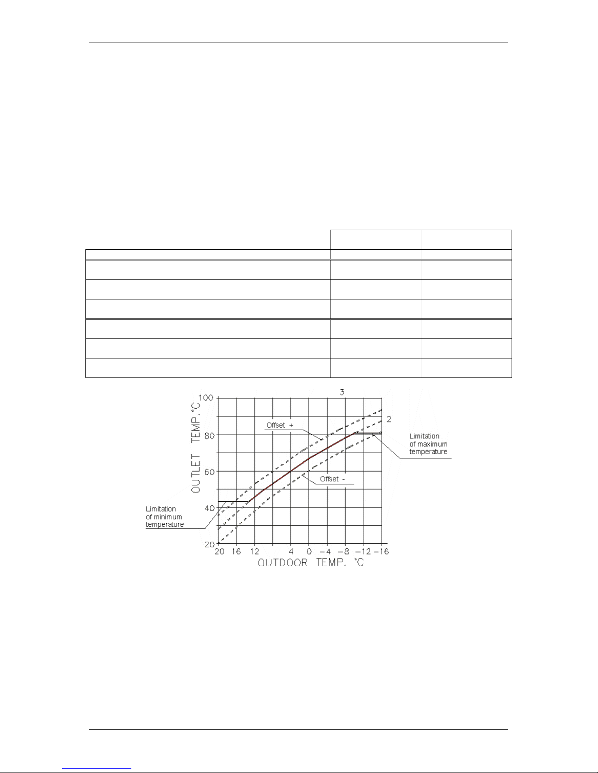
Changing the inclination
When changing the heat ing curve, inclination is changing too, an d that way temperature of the water
in the boiler is changing when the external temperature is low (below + 5
o
C).
Level changes - offset
By offsetting the heating curve for the chosen value, the temperature of the water in the boiler is
changing without changing the shape of the curve.
INSTRUCTIONS FOR USE
We reserve the right of alternations
page 2

TMS-UT-0114-T03-1
Values in the table below are used for the orientation and the user can change them any time as
he/she wishes.
The experience has shown the following (for the average building quality):
when the temperature of the water for the heating changes from 5 to 7
o
C that will change the
room temperature by approximately 2
o
C.
Thermal (heating) processes are slow, all corrections function after some period of time. It
would be better if further corrections were made a day or two later.
To gain experience, we su ggest th at you should write all corr ections ( in th e perio d of s earching f or th e
right parameters) in the protocol of the corrections.
In the table belo w you can find instr uctions how to correct the heating curve for the r adiator heating
depending on the achieved room temperature.
Inclination of the
curve
Offset
Factory settings
1,5
0
Room temperature is too low if the external temperature i s
above + 5oC
Change with the first
lower curve
Add with offset
+ 6oC
Room temperature is too low if the external temperature i s
between + 5oC and - 5oC
Leave the curve 1,5
Add with offset
+ 3oC
Room temperature is too low if the external temperature i s
below - 5oC
Change with the first
higher curve
Leave offset
0oC
Room temperature is too high if the external temperature is
above + 5oC
Change with the first
higher curve
Lower with offset
- 6oC
Room temperature is too high if the external temperature is
between + 5oC - 5oC
Leave the curve 1,5
Lower with offset
- 3oC
Room temperature is too high if the external temperature is
below- 5oC
Change with the first
lower curve
Leave offset
0oC
Sample of modified curve
In combined heating s ystem, radiator and under floor he ating or other heating elem ents, temperature
of the water in the boiler has to be chosen in a way to achieve the highest desired temperature. On the
parts of heating where temperature of the pr imar y flow has to be lower, on e elem ent has to be bui lt in
such as motorized three-way valve that is controlled by room thermos tat, thermostat valve for lim iting
the temperature of the return flow or something similar.
INSTRUCTIONS FOR USE
We reserve the right of alternations
page 3

TRGOVINA TERMOSTROJ d.o.o. 10250 Lučko, F. Puškarića 1d
Tel/Fax +385 1 6531-008, 6531-015, 6531-016 Eurposka unija
e-mail: info@termostroj.com web: http://www.termostroj.com European Union
1.4.5. Limiting the minimum and maximum temperature of the water in the boiler
If the heating curves and offset are selected correctly and the room temperature is falling, in
transitional period in heating seasons (fall, spring) minimal temperature of the water in the boiler has to
be changed.
If the building cannot accumulate heat (sudden and short worming during the day) the necessary
temperature of water in the boiler will be too low and will not keep up the desired room temperature.
Limitation of the maximum temperature of water in the boiler serves more as a protection. Factory
setting is 90
o
C, and we suggest lowering it to approximately 80oC. Limitation of the maximum
temperature of water in the boiler is also used in central heating and domestic water preparation
system, and because of that it is not advisable to lower that temperature too much because the
domestic water will warm up slowly on higher tem per atures .
1.5. Functionality of hot domestic water
1.5.1. Availability
Termo Extra boilers with options W, and Termo PTV boilers enable the preparation of hot water in
separate water storage with heat exchanger.
1.5.2. Description
Domestic water conditi on in g has t he preference order over central heating. At t he moment of signaling
the need for warming up the dom estic water container by the domestic water tem perature sensor, th e
circulation pump of central heating is switched off, and the circulation pump for domestic water
conditioning is switched on.
Heaters regulate the d esired water tem perature in th e boiler th at is 25°C higher t han set va lues of th e
desired domestic water temperature (independent of central heating curve).
Circulation pum p for domestic water conditionin g supplies the container until the desired temperature
of domestic water is re ached, upon which it is switc hed of f with previousl y des crib ed and pro gram m ed
time delay.
If the central heating is off, either floor or radiators’ heating , at the moment of reaching the desired
domestic water tem perature, the desired water temperature in the boiler is set to minimum value of
water temperature in the boiler (stand by).
At repeated requests for heating the domestic water c ontainer, the desired water tem perature in the
boiler is set to 25°C higher than set values of the desired domestic water temperature.
Circulation pump for domestic water cond itioning is s witched on as late as the water tem perature in a
boiler reaches the same or higher temperature than desired value of domestic water temperature.
The 5°C difference for warm water conditioning is programmed. It means that if the desired
temperature of dom estic water tank is 60°C , then the central heat ing wil l be sw itched off and domes tic
water conditioning switc hed on as la te as domestic water temperature is lo wer tha n 55°C, an d heati ng
will be switched on a nd domestic water conditi oning switched off when the temperature in domes tic
water tank reaches 60°C, and when the programmed time of supplemental operation of domestic
water circulation pump has passed.
If the time for domestic water conditioning is longer than 30 minutes, i.e. if the desired temperature of
domestic water tank is not reached within 30 minutes, the process will be automatically interrupted and
switched to the heating regime, which in this case lasts at least 30 minutes.
INSTALACIJSKE UPUTE
Zadržavamo pravo izmjene uputa bez posebne najave

TRGOVINA TERMOSTROJ d.o.o. 10250 Lučko, F. Puškarića 1d
Tel/Fax +385 1 6531-008, 6531-015, 6531-016 Eurposka unija
e-mail: info@termostroj.com web: http://www.termostroj.com European Union
1.6. Frost protection
1.6.1. Availability
Frost protection, as bo iler’s function, is limited to Termo Ex tra boilers with opt ions E, C and W, Termo
Blok boilers with option C and Termo PTV boilers. F or other vers io ns of boilers, frost protecti on c a n b e
provided with the usage of an appropriate room therm ostat. Where frost protec tion is controlled by
room thermostat, please consult room thermostat manuals for more details.
Following topics explain how frost protection is working when it is boiler controlled function (options
C,W).
1.6.2. Domestic water
If the boiler is on for supply and only warm water conditioning is on or only heating or both, the
protection from freezing the water in warm water container switches on automatically when the
temperature sensor of warm water container reads the value below 7°C, signaling switching on by
blinking display, as wel l as the LED diode of the heat er and warm water conditioning, reg ulating the
warm water container temperature to 7°C.
1.6.3. Central heating
If the boiler is on f or supply and heating or both (heating and warm water con ditioning) are off, the
protection from free zing the water in the central hea ting system switches automatica lly on if the water
temperature sensor in th e boiler reads the val ue below 8°C. In this cas e the temperature of water in
the boiler is maintained at 8°C, as long as the conditions of possible freezing do not disappear.
Switching on is signaled by a blinking display as well as the LED diode of the heater and the boiler.
In this case, domestic water conditioning has priority.
In order for the freezing protection system of central heating to operate, the room thermostat should be
in the position of freezing protection as well (other wise, the circulation pum p of central heating would
not operate).
INSTALACIJSKE UPUTE
Zadržavamo pravo izmjene uputa bez posebne najave
TRGOVINA TERMOSTROJ d.o.o. 10250 Lučko, F. Puškarića 1d
Tel/Fax +385 1 6531-008, 6531-015, 6531-016 Eurposka unija
e-mail: info@termostroj.com web: http://www.termostroj.com European Union
2. Using control panels
2.1. Working with standard control panel
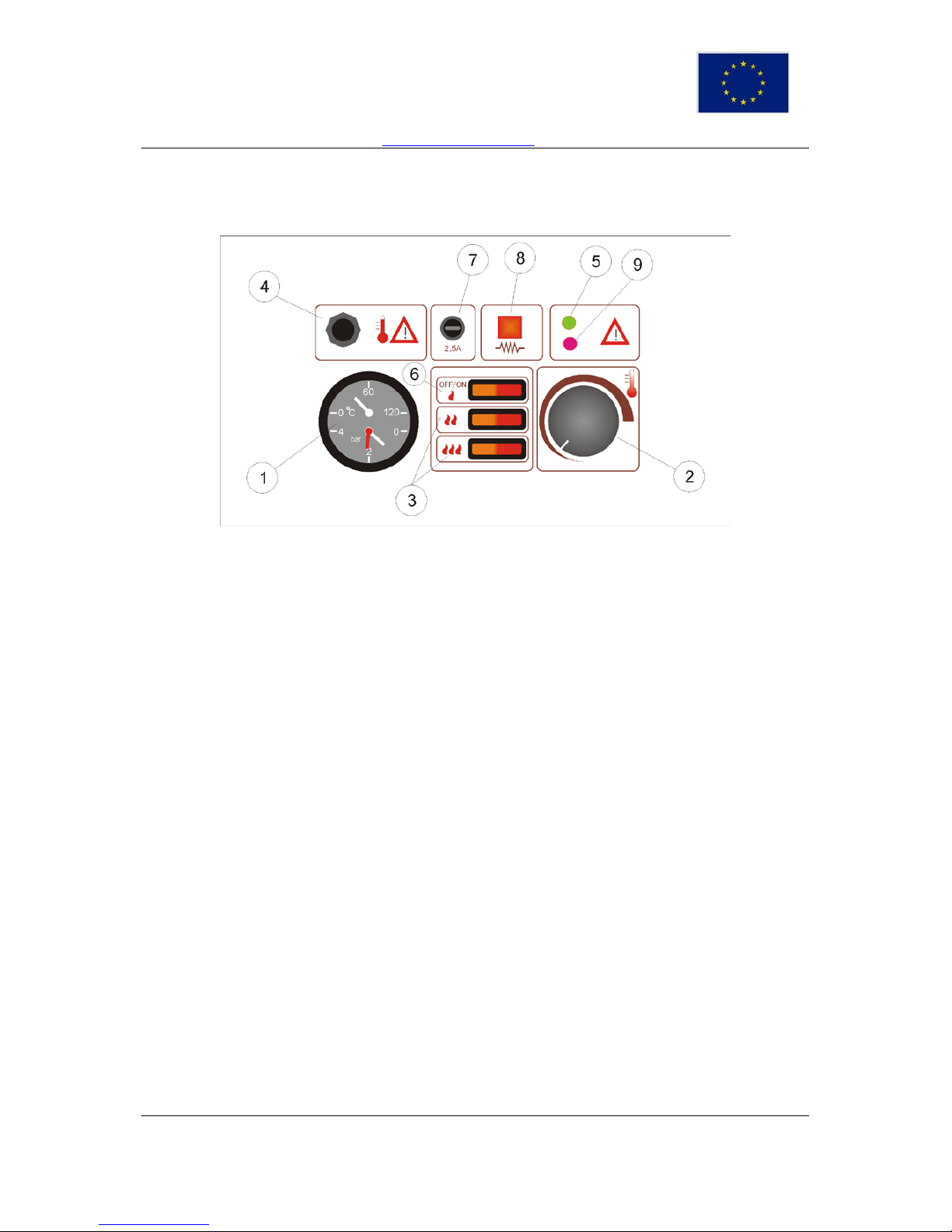
Standard electromechanical control panel
The automatics consists of the following el ements:
1 – Indicator of temperature /pressure in boiler
2 – Working thermostat
3 – Switch for the 2
nd
and 3rd operation stage
4 – Cutout thermostat with manual deactivation (switches off on ca 115
o
C)
5 – Indicator of air appearance in the boiler - air-indicator (also indicates low voltage protection)
6 - Switch for ON/OFF and the 1
st
heating stage
7 – Fuse 2,5A protecting the pump and switches
8 – Indication of heater operation
9 - Indicates low voltage protection - under 180V
Putting on central heating
By switching the switch (6) ON, the central heati ng system is switched on and the firs t power stage is
active. With switch (3) it is possible to control manually the second or the third po wer stage of boiler.
Boilers with 3 stages ha ve soft start for the second and the third stage and s witches (3) have only
limiting function. If the boiler is heating, the light of heat er in operation (8) is on, if heaters are not
working and boiler is in standby only ON/OFF light is on.
Adjustment of desired temperature of central heating
With the help of working thermost at (2) it is possible to select the fixed desire d temperature in boiler.
Working thermostat has range from 20ºC to 80ºC. Recommended temperature is about 60ºC (12
o’clock position).
Air in the boiler (5), red light
If the air appears in the boil er, the signal ization of air in the boiler tur ns on (5) an d the boiler s tops the
operation. In this way the boiler is protected against burning through due to presence of air. To
continue th e operation the boiler should be vented. If the boiler is correctly vented, th e operation of
boiler continues automatically.
Voltage drop (9), red light
If the voltage in the network line drops below 180V by phase, the signalization of under voltage
protection (9) turns on, the boiler automatically switches off in order to protect electronics and
INSTALACIJSKE UPUTE
Zadržavamo pravo izmjene uputa bez posebne najave
TRGOVINA TERMOSTROJ d.o.o. 10250 Lučko, F. Puškarića 1d
Tel/Fax +385 1 6531-008, 6531-015, 6531-016 Eurposka unija
e-mail: info@termostroj.com web: http://www.termostroj.com European Union
contactors inside the boiler. The boiler will automatically continue the operation when the network
voltage reaches values above 180V.
Cutout thermostat - turning on
Cutout thermostat (safety thermostat) (4) protects the boiler against rapid increase of temperature
above 115°C. The fuse turns the boiler off and ejects the RCCB (RCD)-switch.
For boiler to continue working it is necessary to take off the protection cover from the cutout
thermostat and press the red key, upon which the RCCB (RCD)-s witc h sh ould be s witc hed on aga in.
NOTE:
If the room thermostat is on, make sure that it is set on the required room temperature and if
supply batteries are in order, otherwise the boiler will not operate.
2.2. Working with electronic control panels (option E)
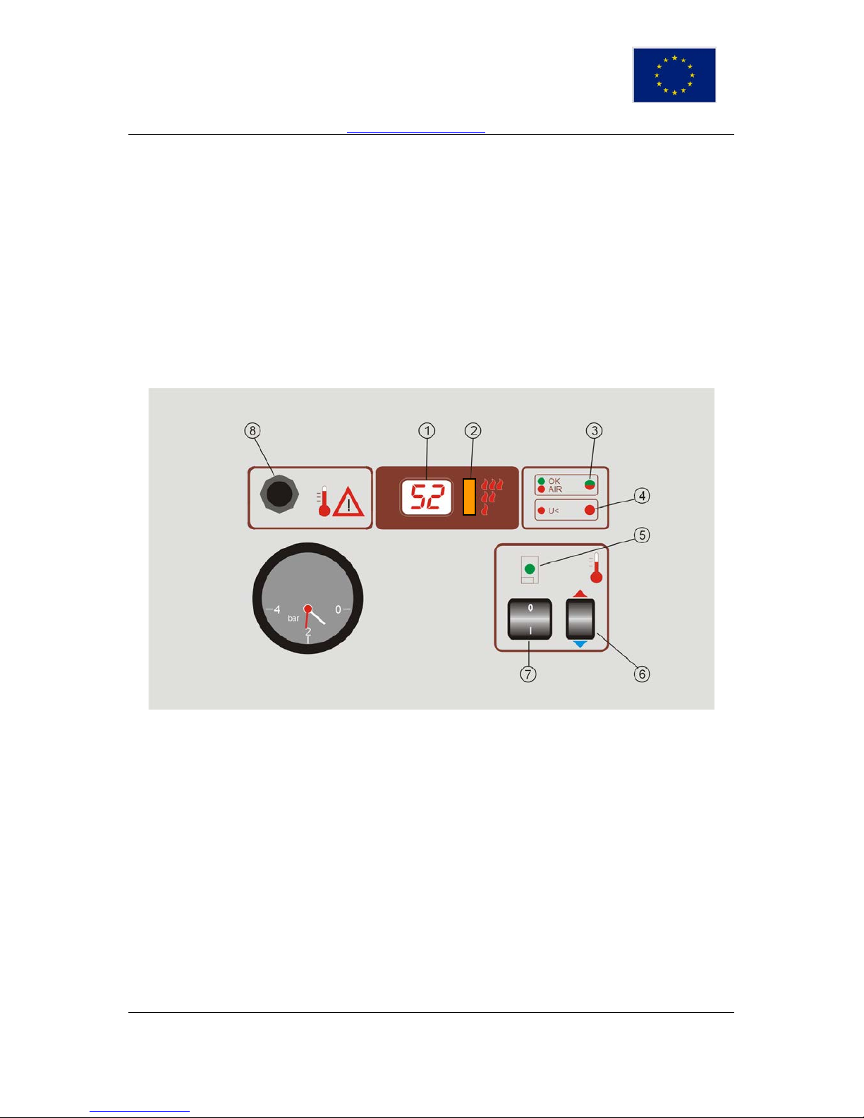
Electronic control panel without external temperature compensation
1. Multipurpose – temperature indicator (temperature of boiler,
adjustment of temperature)
2. Signalization of operation degree of heaters (1, 2, 3)
3. Signalization of the presence of air in the boiler (red light)
4. Signalization of under voltage protection (red light)
5. Signalization of boiler operation (green light)
6. Adjustment of temperature in boiler
7. Switch for central heating switching on and off
8. Thermal fuse
Switching on of central heating
By switching the switch (7) to the p os ition 1, t he c entra l heat in g system is switched on. Upon s witc h ing
on the desired water tem perature in boiler is displa yed for 5 seconds, si gnalization of boiler oper ation
is twinkling (5). After 5 seconds the real temperature in the boiler is displayed (1); if the current
temperature in the boiler meets the desired on e, the signalization lamp of the boiler operation (5) is
switched off.
Adjustment of desired temperature of centra l heating
By pressing the key for te mperature adjus tment (6) the desir ed temperature in the boiler app ears, the
signalization lamp of the boiler operation (5) is twink ling. B y repeated pressing u pw ards or do wnwar ds
it is possible to increase or decreas e the des ired sa nitar y water tem per ature. W hen the tem peratur e is
INSTALACIJSKE UPUTE
Zadržavamo pravo izmjene uputa bez posebne najave

TRGOVINA TERMOSTROJ d.o.o. 10250 Lučko, F. Puškarića 1d
Tel/Fax +385 1 6531-008, 6531-015, 6531-016 Eurposka unija
e-mail: info@termostroj.com web: http://www.termostroj.com European Union
adjusted it is suffic ient to wait for 5 seconds (signalization lam p of the boiler operation ( 5) does not
twinkle) in order for the boiler to memorize new temperature.
Air in the boiler (3), red light
If air appears in the boiler, the signalization of air in t he boiler turns on (3) and the boiler stops the
operation. In this wa y the boil er is protec ted ag ains t burnin g through because of appearance of air. T o
continue the oper ation, the boiler should be vented. If the boiler is c orrectly vented, the opera tion of
boiler continues automatically.
Voltage drop (4), red light
If the voltage in the network line drops below 180V by phase, the signalization of under voltage
protection (4) turns on, the boiler automatically switches off in order to protect electronics and
contactors inside the boiler. The boiler will automatically continue the operation when the network
voltage reaches values above 180V.
Cutout thermostat - turning on
Cutout thermostat (safety thermostat) (8) protects the boiler against rapid increase of temperature
above 115°C. The fuse turns off the boiler and ejects the RCCB (RCD)-switch.
To continue the operation it is necessary to t ake off the protection cover f rom the cutout thermostat
and press the red key, after which the RCCB (RCD)-switch should be switched on again.
2.3. Working with electronic control panels
(option C and W and Termo Blok PTV)
2.3.1. General
Regardless of the selected regulation c urve, the m axim um water temperatur e in the boiler is limited to
90°C for radiator heating and 50°C for floor heating.
Factory setting of the curve is 1,5 for radiator heating.
Factory setting of the curve is 0,6 for under floor heating.
Refer to chapter 1.4. for detailed description of heating curves.
Refer to chapter 1.5. for detailed description of DHW functions.
Refer to chapter 1.6. for detailed description of frost protection.
Refer to chapter 4.8 for detailed description of selecting desired set of heating curves.
INSTALACIJSKE UPUTE
Zadržavamo pravo izmjene uputa bez posebne najave
TRGOVINA TERMOSTROJ d.o.o. 10250 Lučko, F. Puškarića 1d
Tel/Fax +385 1 6531-008, 6531-015, 6531-016 Eurposka unija
e-mail: info@termostroj.com web: http://www.termostroj.com European Union
!
4 0
bar
0
I
OK
AIR
U<
12 1 2
3
4
5
52
2
6
7
11
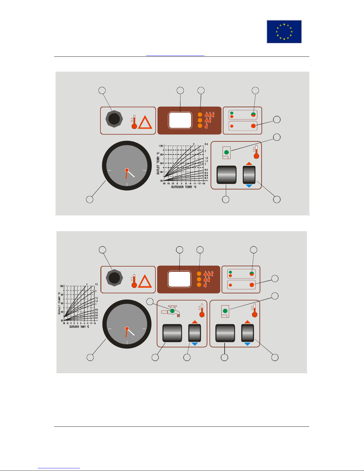
Type 1 – Outdoor temperature compensation
!
4 0
2
bar
0
I
0
I
OK
AIR
U<
12 1 2 3
4
5
6789
10
11
52
Type 2 – Outdoor temperature compensation and sanitary water on Termo Extra or Termo Blok PTV
1. Display
Display of temperatures values reading from KTY probes from + 99
o
C (above +99oC display is blinking)
up to -19oC (below -19oC the display shows - -). Display of desired temperature or curve during setup.
Following warning signals can be displayed:
INSTALACIJSKE UPUTE
Zadržavamo pravo izmjene uputa bez posebne najave

TRGOVINA TERMOSTROJ d.o.o. 10250 Lučko, F. Puškarića 1d
Tel/Fax +385 1 6531-008, 6531-015, 6531-016 Eurposka unija
e-mail: info@termostroj.com web: http://www.termostroj.com European Union
P1 – frost protection for sanitary water is active
P2 – frost protection for central heating is active
o1 or c1 – thermal sensor for boiler temperat ur e is not connected or is short-circuited
o2 or c2 – thermal sensor for external temperature is not connected or is short-circuited
o3 or c3 – thermal sensor for DHW temperature is not connected or is short-circuited
2. Led diodes of heaters stages
The number of lighted diodes corresponds to the number of momentarily active heater operations
stages.
3. Led diode OK/air in boiler
If there is no air in the boiler, the diode becomes green. If the air appears in the boiler, the diode
becomes red and at the same time the operation of the device is stopped. After venting, the diode
automatically changes the color to green and operation of the boiler is continued.
4. Led diode too low supply voltage
If the net voltage falls below 170 V red light appears and at the same time the operation of the device is
stopped.
5. Led diode of central heating
It indicates the operation of circulation pump of heating, provided that the room thermostat is on.
6. Push button for adjustment of heating characteristics
7. Switch – heating on/off
8. Push-button for adjusting characteristics of sanitary water conditioning
9. Sanitary water conditioning on/off
10. Led diode in course of sanitary water conditioning,
Indicates the circulation pump operation for sanitary warm water conditioning.
11. Indicator of water pressure in heating syste m.
12. Safety thermostat
INSTALACIJSKE UPUTE
Zadržavamo pravo izmjene uputa bez posebne najave
TRGOVINA TERMOSTROJ d.o.o. 10250 Lučko, F. Puškarića 1d
Tel/Fax +385 1 6531-008, 6531-015, 6531-016 Eurposka unija
e-mail: info@termostroj.com web: http://www.termostroj.com European Union
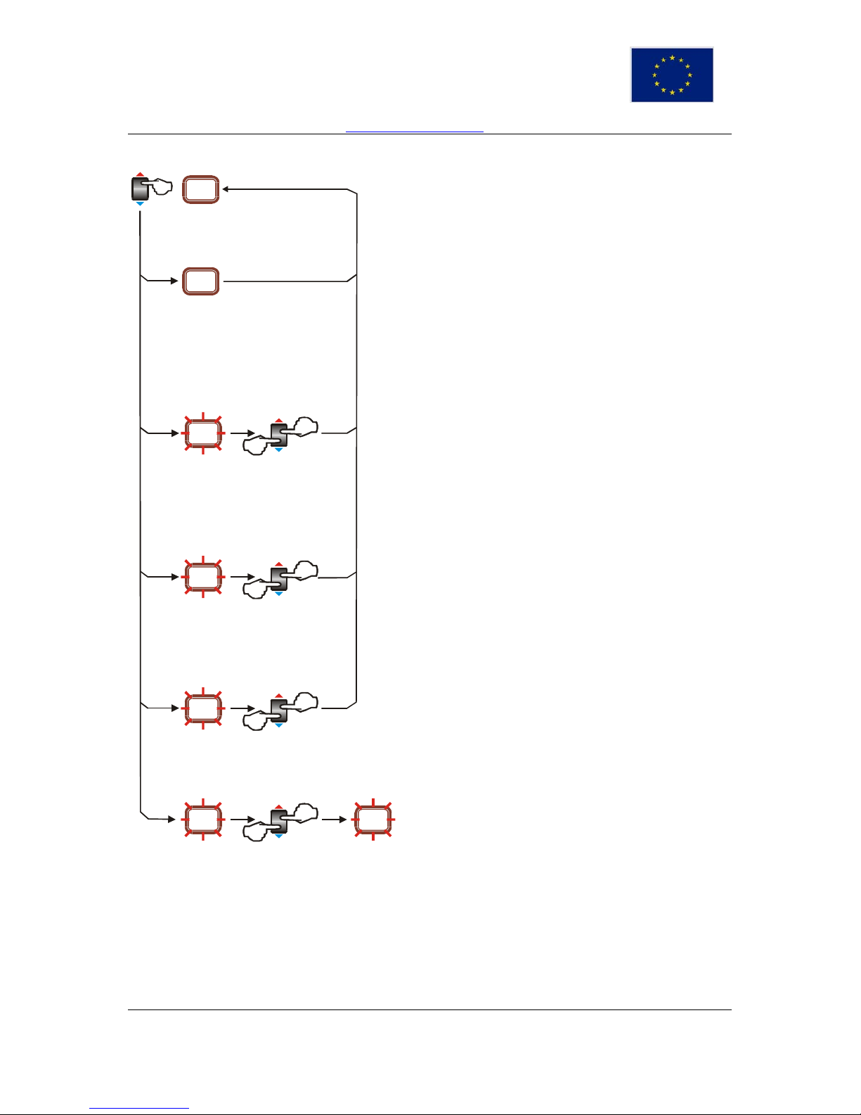
2.3.2. Central heating functions
>5 sec
0.6
41
>5 sec
>10 sec
>5 sec
3
32
>5 sec
<5 sec
>15 sec
>5 sec
90
>20 sec
60 32
>5 sec
Display of desired temperature inside the boiler
By pressing the key (6) user can see the desired temperature inside the
boiler.(calculated from the selected correction curve)
The Display shows the desired temperature of water in the boiler. The value
is displayed for 5 s, after which display normally shows the real temperature
of water in the boiler.
Correction curve selection
By pressing the key (6) user can enter curve selection menu.
The number of set curve is blinking, according to which the correction of
water temperature in the boiler is corrected in relation to external
temperature. Values are between 1 and 3 or 0,2 and 0,9. Curves between 1
and 3 are for radiators’ central heating and curves 0,2 to 0,9 are for under
floor heating.
By pressing the key, numbers of curves are changing with the step of 0, 1
within the set, according to the diagram on t he front plate. If t he key is hel d
pressed less than 5 s the display value becomes valid regulation curve.
Limiting maximum boiler power
By pressing the key (6) user can limit the power level.
By pressing the key it is possible to select 1 2 or 3 as number of avai labl e
power levels. If the key is held pressed less than 5 s the selected power
level mode will become active.
Boilers from 6 to 16 kW have only two power levels.
Limiting maximum temperature inside the boiler
By pressing the key (6) user can limit maximum temperature inside the
boiler.
Factory defined maximum temperature starts to blink. By pressing up or
down user can set new maximum temperature. If the key (6) is held pressed
less than 5 s the selected maximum temperature will become active.
This temperature represents maximum
temperature that can be
achieved regardless of selected curve.
Manual selection of desired t emper atur e inside the boiler
By pressing the key (6) user can set temperature in the boiler, regardless of
previously selected curve.
Desired temperature starts t o blink. By pressing the key up or down user
can select fixed temperature in the boiler. If the key is held pressed less
than 5 s the fixed temperature becomes active.
When boiler is in fixed temperature mode, the LED display blinks while
displaying current temperature in the boiler. Us er can just press the key (6)
up or down for next change of fixed temperature.
When boiler is in fixed temperature mode, all correction curves are
disregarded. To return to the correction curve mode, the boiler must
be switched off and back on using ON/OFF switch.
INSTALACIJSKE UPUTE
Zadržavamo pravo izmjene uputa bez posebne najave
TRGOVINA TERMOSTROJ d.o.o. 10250 Lučko, F. Puškarića 1d
Tel/Fax +385 1 6531-008, 6531-015, 6531-016 Eurposka unija
e-mail: info@termostroj.com web: http://www.termostroj.com European Union
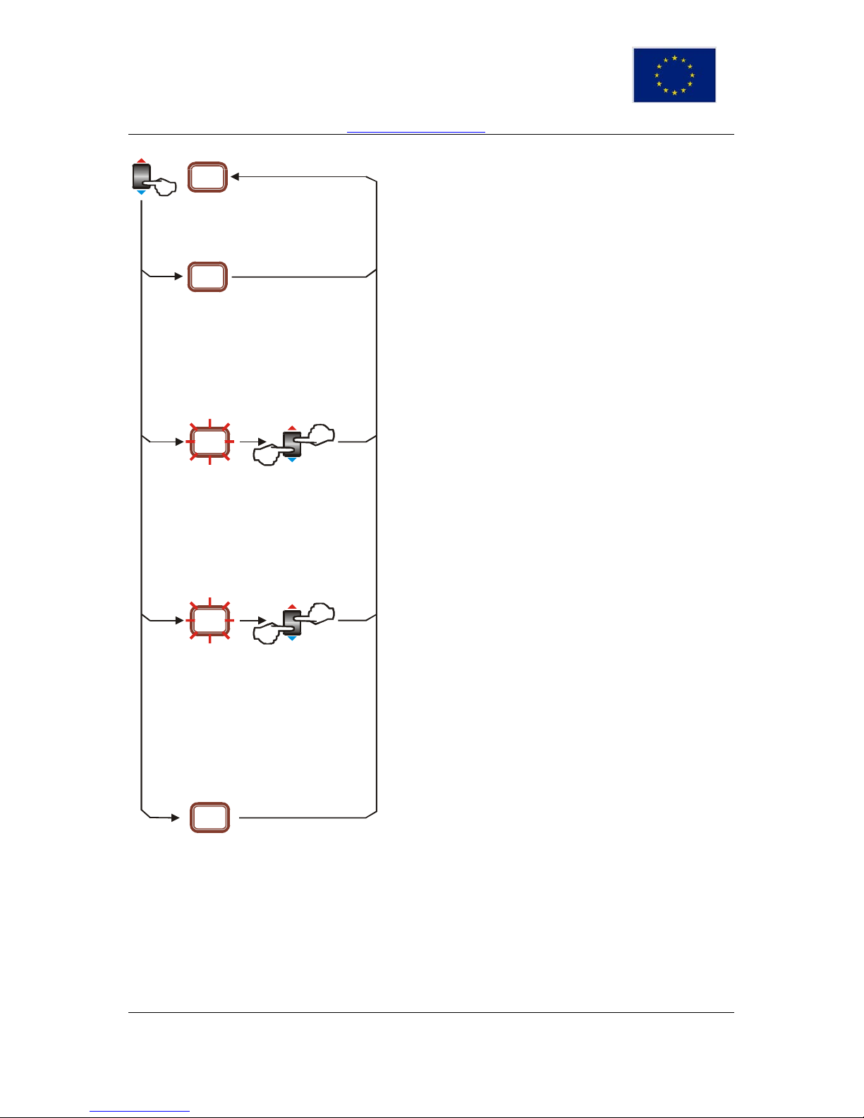
Continuation...
>5 sec
0
-1
>5 sec
>10 s ec
>5 sec
20
32
>5 sec
<5 sec
>15 s ec
1.4
Display of external temperature
By pressing the key (6) user can see external temperature.
The Display shows the external temperature. The value is displayed for 5 s, after
which the display normally shows the real temperature of water in the boiler.
Offset of currently selected correction curve
By pressing the key (6) user can enter the curve selection menu.
The LED display will show current offset in ˚C. Offset does not affec t maxim al o r
minimal temperature, they are set in absolute values
By pressing the key (6) it is possible to change offset in steps of 1˚C.
Factory setting is 0˚C.
Offset range is from –9 to +20˚C.
If the key is held pressed less than 5 s t he displayed value becom es valid offset
in ˚C.
Setting the minimal temperature inside the boiler
By pressing the key (6) user can select minimal temperature inside the boiler.
Minimal temperature starts blinking.
Factory setting is 27°C for radiator heating.
Factory setting is 20°C for under floor heating.
By pressing the key user can select the des ired temperature in range from 10 to
50°C. Temperature changes in steps of 1°C. If the key is held pressed less t han
5 s the value from the display becomes the desired minimal boiler temperature.
Displaying software version and factory reset
By pressing the key (6) longer than 15 seconds, the LED will show the software
version and the factory reset of central heating parameters will occ ur.
INSTALACIJSKE UPUTE
Zadržavamo pravo izmjene uputa bez posebne najave
TRGOVINA TERMOSTROJ d.o.o. 10250 Lučko, F. Puškarića 1d
Tel/Fax +385 1 6531-008, 6531-015, 6531-016 Eurposka unija
e-mail: info@termostroj.com web: http://www.termostroj.com European Union
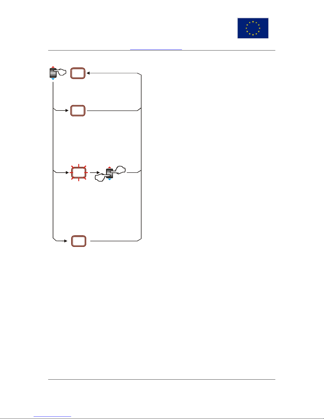
2.3.3. Domestic water functions (control panel type 2)
>5 sec
50
50
>5 sec
>10 s ec
32
>5 sec
<5 sec
1.4
Display of desired temperature of domestic water
If the key is held pressed less than 5 s the LE D display will show the desired
temperature in domestic water storage. The value is dis played for 5 seconds,
after which the display normally shows the real temperature of water in the
boiler.
Setting the desired temperature in domestic water storage
By pressing the key (8) user can enter the domestic water temperature menu.
The desired water temperature in domestic water storage is blinking.
By pressing the key (8) the value of desired domestic water temperature in
domestic water storage is changing in steps of 1°C. I f the key is held pressed
less than 5 s the value from the display becomes the desired dom estic water
temperature.
Possible adjustment is from 10°C up to 65°C.
Factory adjustment is 50°C.
Displaying software version and factory reset
By pressing the key (8) longer than 15 seconds, the LED will show the software
version and the factory reset of the central heating parameters will occur.
INSTALACIJSKE UPUTE
Zadržavamo pravo izmjene uputa bez posebne najave

TRGOVINA TERMOSTROJ d.o.o. 10250 Lučko, F. Puškarića 1d
Tel/Fax +385 1 6531-008, 6531-015, 6531-016 Eurposka unija
e-mail: info@termostroj.com web: http://www.termostroj.com European Union
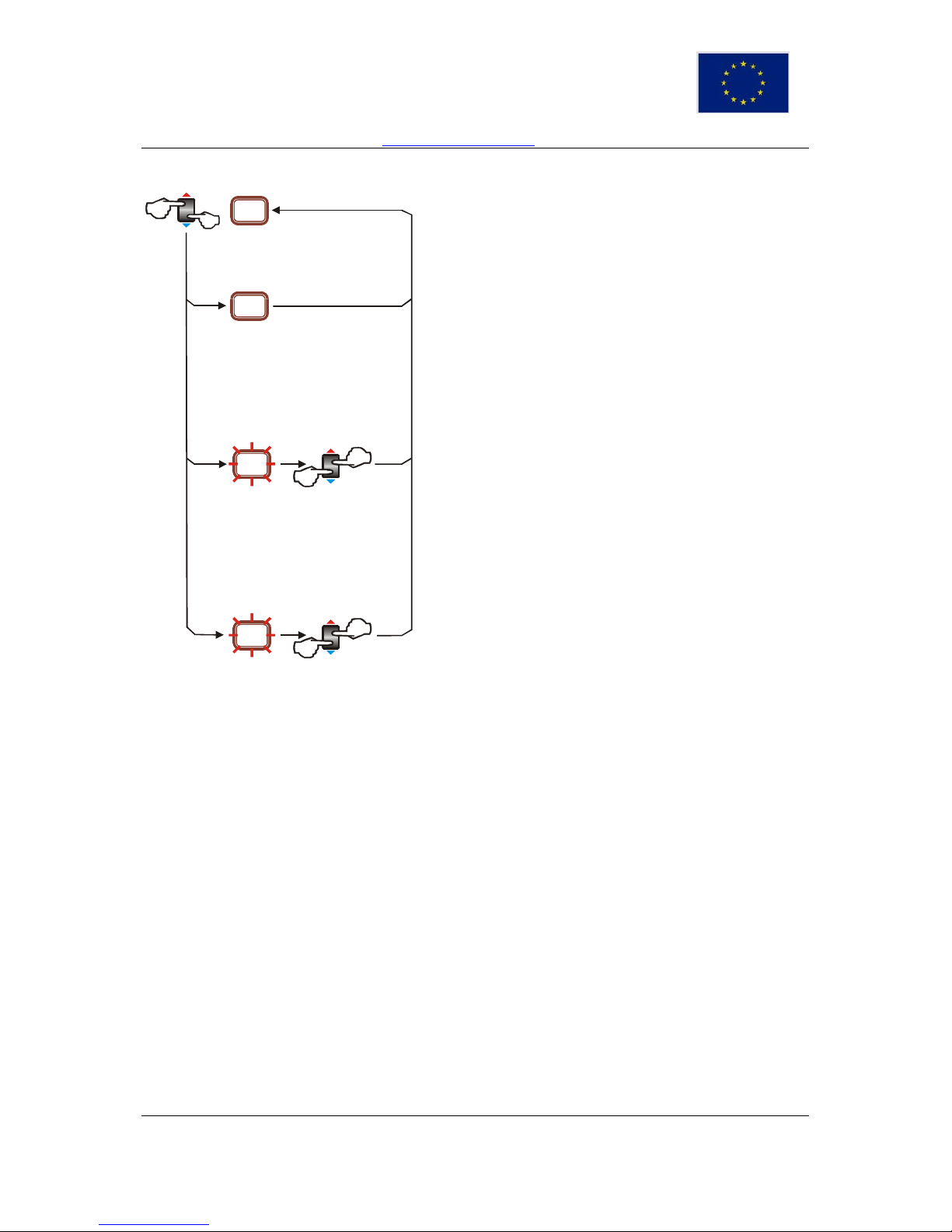
Continuation...
>5 sec
1.0
36
>5 sec
>10 s ec
>5 sec
20
32
>5 sec
<5 sec
>15 s ec
1.4
Display of current temperature in domestic water storage
By pressing the key (8) user can s elect the display of current tem perature in the
domestic water storage. The value is dis played for 5 s, after which the display
normally shows the real temperature of water in the boiler.
Setting additional working time of domestic water pump
By pressing the key (8) user can set up addi tional working time of domestic water
pump.
The time of s upplemental operation of circulation pump operation for domestic
water conditioning is blinking.
By pressing the key the time is changing from 0,1 min up to 19 min. with the step
of 1 digit. If the key is held pressed less than 5 s, the value from a display
becomes valid time of supplemental operation of circulation pump for domestic
warm water conditioning.
Factory setting is 1 min.
Setting stand by temperature inside boiler
By pressing the key (8) user can setup stand by temperature inside the boiler.
The LED will show current standby temperature inside the boiler.
Pressing the key (8) will change standby temperature in range from 10°C to
50°C by 1°C. If t he key is held pressed less than 5 s the value from the display
becomes the valid standby temperature inside the boiler.
Displaying software version and factory reset
By pressing the k ey (8) longer than 15 seconds, the LED will show the software
version and the factory reset of central heating parameters will occ ur.
INSTALACIJSKE UPUTE
Zadržavamo pravo izmjene uputa bez posebne najave
TRGOVINA TERMOSTROJ d.o.o. 10250 Lučko, F. Puškarića 1d
Tel/Fax +385 1 6531-008, 6531-015, 6531-016 Eurposka unija
e-mail: info@termostroj.com web: http://www.termostroj.com European Union
2.3.4. Central heating functions with heating curves disabled
>5 sec
4 1
4 1
>5 sec
>10 sec
>5 sec
3
32
>5 sec
<5 sec
Display of desired temperature in boiler
If the key (6) is held pressed less than 5 s the LED display will show the desired
temperature in the boiler. The value is displayed for 5 seconds, after which the
display normally shows the real temperature of water in the boiler.
Setting of the desired temperature in the boiler
By pressing the key (6) user can enter the boiler temperature menu.
The desired boiler temperature is blinking.
By pressing the key (6) UP or DOW N, the desi red boiler temperat ure can be set
in steps of 1°C.
If the key is held pressed less than 5 s the value from the display becomes the
desired boiler temperature.
Possible adjustment is from 20°C up to 90°C for radiator heating.
Possible adjustment is from 15°C up to 45°C for under floor heating.
Limiting maximum power of the boiler
By pressing the key (6) user can limit the power level.
By pressing the key it is possible to select 1 2 or 3 as number of the available
power levels. If the key (6) is hel d pressed less than 5 s the s el ected power level
mode will become active.
Boilers from 6 to 16 kW have only two power levels.
INSTALACIJSKE UPUTE
Zadržavamo pravo izmjene uputa bez posebne najave

TRGOVINA TERMOSTROJ d.o.o. 10250 Lučko, F. Puškarića 1d
Tel/Fax +385 1 6531-008, 6531-015, 6531-016 Eurposka unija
e-mail: info@termostroj.com web: http://www.termostroj.com European Union
3. Maintenance
3.1. Periodic checkin g
We recommend the inspection of the d evice once a year by the auth orized service provider (before
heating season). This s ervice is not included in the warr anty. During the inspection all electric and
water connections should be tightened, the system should be vented and – if necessary – filled
up, valves and general functionality of the device should be checked.
RCCD switch - pressing the TEST button must disconnect the RCCD switch. This testing
procedure insures that switch is functioning properly. We recommend this test once or twice in
heating season.
Safety thermostat – we r ecommended to check safety thermostat before every heating season
by heating up the sensor with heating fan or lighter over 100°C
must actuate overheating
protection by switching off the RCCD switch.
Safety valve should be checked once a year (before the beginning of heating season) to ensure
proper functioning and avoiding appearance of water calculus.
If the boiler is not conn ected to the room ther mostat or if the boiler is out of function duri ng the winter
time, there is a danger of installation freezing.
In this case the system should be filled with antifreeze liquid for central heating, and if this is not
possible water should be drained out.
3.2. Cleaning
It is not permitted to use aggressive media (e.g. gasoline, kerosene or solvent) for cleaning
the product. Media for cleaning plastics or dishwashing media can be used for the external
shell and decorative cover. Control panel should be cleaned with dry or moist cloth (not wet).
3.3. Central heating system
If the boiler is not connect ed to the room thermost at (Termo boilers without C or W option), or if the
boiler is out of function during wintertime, there is a danger of installation freeze. In this case the
system should be filled with antifree ze liquid for central h eating, if this is not possible w ater should be
drained out of the system with the help of charge and discharge.
The recommended pressure of central heating installation is 0,15 mpa (1,5 bar), the
maximum pressure is 0,25 mpa (2,5 bar).
3.4. Starting the pump manually
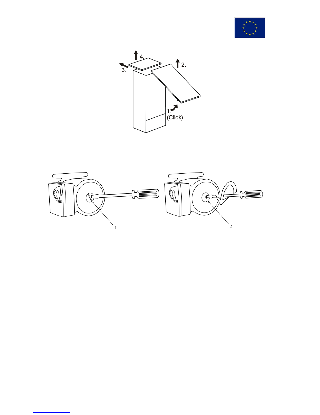
In order to access the pump, remove the front cover of the boiler as described below. In most cases
steps 1 and 2 are sufficient.
INSTALACIJSKE UPUTE
Zadržavamo pravo izmjene uputa bez posebne najave
TRGOVINA TERMOSTROJ d.o.o. 10250 Lučko, F. Puškarića 1d
Tel/Fax +385 1 6531-008, 6531-015, 6531-016 Eurposka unija
e-mail: info@termostroj.com web: http://www.termostroj.com European Union
Grasp the front case by its sides, pull it towards the front and remove it by lifting it off the unit, push the
top cover backwards and lift it of the unit.
To start the pum p it is nec essar y to turn off the prote ction pl ug on its f ront s ide (1) , below which ther e
is an axis with the groove for screwdriver. Using the screwdriver, the pump (2) should be turned
several times in the direction of the arrow on the pump head and the boiler should be put on again.
When the pump starts the operation the temperature of water in the boiler and the temperature of
sanitary water should be selected. The optimal temperature for central heating is between 60 and
70°C.
If the room thermostat is connected to the boiler, the desired r oom temperature should be adjus ted
according to the instructions of the producer of the room thermostat.
INSTALACIJSKE UPUTE
Zadržavamo pravo izmjene uputa bez posebne najave

TRGOVINA TERMOSTROJ d.o.o. 10250 Lučko, F. Puškarića 1d
Tel/Fax +385 1 6531-008, 6531-015, 6531-016 Eurposka unija
e-mail: info@termostroj.com web: http://www.termostroj.com European Union
4. Survey of possible malf unct ions and irregularities in opera t ion
MALFUNCTION CAUSE ELIMINATION
- there is no voltage
on the control panel
at switching on
- there is no power supply from the net
on one or more phases
- fuse 2,5A on the control panel is
burned through
- RCCB switch is disconnected
- replace fuse 2,5A and check
the cause of burning
- contact authorized service
personnel to resolve the
problem
- By switching on,
the switches on the
control panel display
the voltage, but the
boiler does not heat
- check the adjustment of the room
thermostat,
- limiting thermostat is activated
- indicator of air presence in the boiler
blocked the operation,
- defective switch,
- operation thermostat is defective,
- heaters are burned through
- check the set temperature on
the room thermostat, replace
batteries, or the room
thermostat is faulty,
- deaerate the boiler in order to
turn off the lamp “air in boiler”
- temperature in
boiler is on desired
value, but radiators
do not heat
- circulation pump does not operate,
- air stopper on central heating
install ation prevents circulation
- start mechanical pump
(CHAPTER 4.)
- deaerate installation
- boiler does not
provide enough
heat
- one phase is m is sing on supply
- in two-stage thermostats the second
stage is not functioning
- the second or the third stage is not
manually turned on,
- one switcher is defective,
- a part of heater is burned through
- in a three-phase system the three
different phases are not brought to the
boiler
- check fuses on the main
panel,
- contact authorized service
personnel to resolve the
problem
- the switcher can
be heard while
operating (it
buzzes)
radio and TV-
interferences
- poor voltage in the net
- defective switcher
- contact authorized service
personnel to resolve the
problem
- when tur n ing on
or off the
operation
thermostat,
radio and TVinterferences
occur
- defective operation thermostat,
- defective blockade (RC – protection)
- contact authorized service
personnel to resolve the
problem
- boiler in
operation “roars”
- the system is not well deaerated,
- defective heater
- deaerate the system
- contact authorized service
personnel to resolve
problem
- pressure in the
system varies
- defective expansion vessel,
- the vessel pressure is too low or too
high
- contact authorized service
personnel to resolve the
problem
INSTALACIJSKE UPUTE
Zadržavamo pravo izmjene uputa bez posebne najave
TRGOVINA TERMOSTROJ d.o.o. 10250 Lučko, F. Puškarića 1d
Tel/Fax +385 1 6531-008, 6531-015, 6531-016 Eurposka unija
e-mail: info@termostroj.com web: http://www.termostroj.com European Union
- the actual
temperature in the
boiler is higher than
the desired
temperature and the
safety thermostat is
activated
- defective contactors
- defective operation thermostat
- contact authorized service
personnel to resolve the
exact source of the
problem
- RCCB switch
disconnects
- defective heater,
- humidity on conductors,
- safety thermostat is activated
- check leakage,
- contact authorized service
personnel to resolve the
exact source of the
problem
- RCCB switch
cannot be reset
- safety thermostat is activated
- pre-reset safety thermostat
and then the RCCB switch
- contact authorized service
personnel to resolve the
exact source the of
problem
‘Ulaganje u budućnost’
‘Investing for the future’
Projekt sufinancira Europska unija iz Europskog fonda za regionalni razvoj.
Project is co-founded by the European Union’s Regional Development Fond.
INSTALACIJSKE UPUTE
Zadržavamo pravo izmjene uputa bez posebne najave

TRGOVINA TERMOSTROJ d.o.o. 10250 Lučko, F. Puškarića 1d
Tel/Fax +385 1 6531-008, 6531-015, 6531-016 Eurposka unija
e-mail: info@termostroj.com web: http://www.termostroj.com European Union
INSTALACIJSKE UPUTE
Zadržavamo pravo izmjene uputa bez posebne najave
TRGOVINA TERMOSTROJ d.o.o. 10250 Lučko, F. Puškarića 1d
Tel/Fax +385 1 6531-008, 6531-015, 6531-016 Eurposka unija
e-mail: info@termostroj.com web: http://www.termostroj.com European Union
ELECTRIC BOILERS FOR CENTRAL HEATING
TERMO-Blok
TERMO-Extra
TERMO-Blok PTV
INSTRUCTIONS FOR INSTALLATION
‘Ulaganje u budućnost’
‘Investing for the future’
Projekt sufinancira Europska unija iz Europskog fonda za regionalni razvoj.
Project is co-founded by the European Union’s Regional Development Fond.
INSTRUCTIONS FOR INSTALLATION
We reserve the right of alternations

TMS-UT-0114-T01-1
INSTRUCTIONS FOR INSTALLATION
We reserve the right of alternations

TMS-UT-0114-T01-1
Contents
1. Introduction ....................................................................................................................... 1
1.1. Applicable documents ................................................................................................. 1
1.2. Retention of documents .............................................................................................. 1
1.3. Introduction ................................................................................................................. 1
1.4. Heating curves ............................................................................................................ 1
1.4.1. Availability of heating curves................................................................................. 1
1.4.2. About Heating curves ........................................................................................... 2
1.4.3. Why does the characteristic heating curve have to be set? .................................. 2
1.4.4. Corrections of the room temperature .................................................................... 2
1.4.5. Limiting the minimum and maximum temperature of water in the boiler ................ 4
1.5. Functionality of hot domestic water ............................................................................. 4
1.5.1. Availability ............................................................................................................ 4
1.5.2. Description ........................................................................................................... 4
1.6. Frost protection ........................................................................................................... 5
1.6.1. Avaliability ............................................................................................................ 5
1.6.2. Domestic water ..................................................................................................... 5
1.6.3. Central heating ..................................................................................................... 5
2. Boiler specifications ........................................................................................................... 6
2.1 Dimensions .................................................................................................................. 6
2.2 Expansion Vessel Characteristics (Termo Blok and Termo Blok TV Boilers) ...............10
2.3. Power supply characteristics 230V/400V ...................................................................10
2.4. Function elements of Termo boilers ...........................................................................11
3.0 General requirements .....................................................................................................14
3.1. Contents included in delivery .....................................................................................14
3.2 Preliminary remarks ....................................................................................................14
3.3. Recommendations for various installation types.........................................................15
3.4. Installation site ...........................................................................................................15
3.4.1. Position of a boiler ...............................................................................................15
3.4.2. Power supply .......................................................................................................16
3.5. System requirements ..............................................................................................16
3.5.1. Pipe work.............................................................................................................16
3.5.2. Cleansing and flushing the system ......................................................................16
3.5.3. Filling and preparing heating system ...................................................................17
3.5.4. Pressure relief valve ............................................................................................17
3.5.5. Pressure gauge ...................................................................................................17
3.5.6. Expansion vessel .................................................................................................17
3.5.7. Circulating pump..................................................................................................17
3.5.8. Venting ................................................................................................................17
4. Boiler installation sequence ..............................................................................................18
4.1. Transporting the appliance .........................................................................................18
4.2. Select position for boiler .............................................................................................18
4.3. Fitting the boiler hanging bracket ...............................................................................18
4.4. Removing/fixing the front and top case ......................................................................19
4.5. Pipe work connection .................................................................................................19
4.6. Power supply connection ...........................................................................................20
4.7. Connecting temperature sensors or external electrical controls .................................20
4.7.1. Accessing connection plate .................................................................................20
4.7.2. Connecting external temperature sensor .............................................................21
4.7.3. Connecting domestic hot water temperature sensor ............................................21
INSTRUCTIONS FOR INSTALLATION
We reserve the right of alternations

TMS-UT-0114-T01-1
4.7.4. Connecting room thermostat and time switch ......................................................23
4.7.5. Connecting external pump on Termo Extra boilers ..............................................23
4.8. Selecting set of heating curves ..................................................................................24
4.9 Filling the heating system ........................................................................................24
5. Commissioning .................................................................................................................25
5.1. Central heating system check ....................................................................................25
5.2. Preliminary electrical check ........................................................................................25
5.3. Changing the speed of pump for central heating ........................................................25
5.4. Working with standard control panel ..........................................................................26
5.5. Working with electronic control panels (option E) .......................................................27
5.6. Working with electronic control panels (option C and W and Termo Blok PTV) ..........28
5.6.1. General ...............................................................................................................28
5.6.2. Central heating functions .....................................................................................30
5.6.3. Domestic water functions (control panel type 2)...................................................32
5.6.4. Central heating functions with heating curves disabled ........................................34
5.6.4.1 Access to special service menu .........................................................................35
5.7. Starting the pump manually .......................................................................................36
6. Maintenance .................................................................................................................36
6.1. Periodic checking .......................................................................................................36
6.2. Cleaning.....................................................................................................................36
7. Survey of possible malfunctions and irregularities in operation .........................................37
INSTRUCTIONS FOR INSTALLATION
We reserve the right of alternations

TMS-UT-0114-T01-1
1. Introduction
Thank you for the confidence you have shown to us by purchasing our central heating boiler.
In order to use the boiler to the utmost correctly and safely, and above all economically, read
thoroughly these instructions before continuing with installation.
The appliances must be installed by a competent person, who is responsible for adhering to
the existing regulations, rules and g u idelines.
1.1. Applicable documents
The following additional documents are provided with the appliance:
For the owner of the system:
Instructions for use
Warranty card
For the qualified technician:
Instructions for installation
Electrical drawing for the appliance
1.2. Retention of documents
Please pass on this installation manual to the owner of the system. The owner should retain the
manuals so that they are available when required.
1.3. Introduction
TERMO-Extra and TERMO-Blok are economical central heating boilers that may be used as an
independent or additional source of heat.
TERMO-Extra and TERMO-Blok boilers offer you a possibility to reduce the power of the heater if
necessary. The power may be switched on automatically whe n necessary with built -in step regulator
or manually with s witches on the contr ol board. In this way it is possible to adapt the boiler to the
utmost to circumstances on the spot.
The boiler operates on a principle of rapid heat in g s maller water quantities, s o th at exploiting energy is
already 100%.
They are particularly suitable for heating smaller business premise, where you are short of space
(small apartments, ef ficiency apartments, representation offices, smaller coffee-shop spaces etc .) or
for heating larger spaces in early season when the main boiler is over dimensioned.
TERMO-Extra boilers are manufactured only with upper connecti ons. Temperature operation area is
from 20
o
C to 90 oC.
TERMO-Extra and TERMO-Blok are designed in such a way that in apartment-contained central
heating they can fit well with your furniture.
1.4. Heating curves
1.4.1. Availability of heating curves
Use of heating curves, temperature compensation, is limited to Termo Extra boilers with options C and
W, Termo Blok boilers with option C and Termo PTV boilers.
Page 1
TMS-UT-0114-T01-1
1.4.2. About Heating curves
The modern way of heat ing is based on energy savi ng and automatic adjustments to warm up the
space.
To achieve the required tem perature electric bo iler with electronic contro l panel heats the water in the
boiler automaticall y depend ing on th e extern al tem per ature. T here is no need to look af ter the m inimal
working temperature bec ause electric boiler s do not dew and t hat means that th e temperature of the
water in the boiler is at the same time the temperature in the heating elements (for example in
radiators, convectors etc.).
To achieve the desired room temperature, the characteristic heating curve has to be chosen
depending on the characteristics of the object and the heating system.
Factory defined curves
If the heating curve is set optimally for heating of your apartment or house, corrections will not
be necessary.
1.4.3. Why does the characteristic heating curve have to be set?
After the first settings of the heating curve authorized person can adjust, correct that curve if
necessary.
Every heating room is bui lt up d if f er entl y. Dif f erent hea t ing el ements and heating syst ems can be used
(radiators, under floor or combined heating) and every building has a different thermal insulation.
For the maximum exploitation of the heating and maximum energy savings, characteristic heating
curve has to be set using the parameter on the control panel, in a way that the chosen heating curve is
suitable for the heating system and for the quality of the building.
1.4.4. Corrections of the room temperature
Based on the experie nce, fac tory settin gs of th e device are f or the average insulated object and room
temperature of 22
o
C. If factory settings are not adeq uate for achieving the desired room temperat ure,
supplemental adjustments of the standard heating curves can be made.
Changing the inclination
When changing the heating curve, inclination is changing too, and in that way the temperature of
water in the boiler is changing when the external temperature is low (below+ 5
o
C).
Level changes - offset
By offsetting the he ating cu rve for th e chosen value the temperat ure of water in t he boiler is chang ing
without changing the shape of the curve.
Page 2
TMS-UT-0114-T01-1
Values in the table below are used for the orientation and the user can change them any tim e as
he/she wishes to.
Experience has shown the following (for the average building quality):
when the temperature of water for heating changes from 5 to 7
o
C that will change the room
temperature by approximately 2
o
C.
Thermal (heating) pro cesses are slow, all corrections function after a period of time. It would
be better if further corrections were made a day or two later.
To gain experience, we su ggest that you should write all corrections ( within a period of searchin g for
the right parameters) in the protocol of the corrections.
In the table belo w you can find instructions how to correct the heat ing curve for the radiator heating
depending on the achieved room temperature.
Inclination of the
curve
Offset
Factory settings
1,5
0
Room temperature is too low if the external temperature is
above + 5oC
Change with the first
lower curve
Add with offset
+ 6oC
Room temperature is too low if the external temperature i s
between + 5oC and - 5oC
Leave the curve 1,5
Add with offset
+ 3oC
Room temperature is too low if the external temperature is
below - 5oC
Change with the first
higher curve
Leave offset
0oC
Room temperature is too high if the external temperature is
above + 5oC
Change with the first
higher curve
Lower with offset
- 6oC
Room temperature is too high if the external temperature is
between + 5oC - 5oC
Leave the curve 1,5
Lower with offset
- 3oC
Room temperature is too high if the external temperature is
below - 5oC
Change with the first
lower curve
Leave offset
0oC
Sample of modified curve
In a combined heating system, radiator and under floor heating, or other heating elements, the
temperature of water in the boiler has to be chosen in a way to achieve the highest desired
temperature. On the parts of heating where temperature of the primary flow has to be lower, one
element has to be built in suc h as motorized three-way v alve that is controlled by room therm ostat,
thermostat valve for limiting the temperature of the return flow or something similar.
Page 3
 Loading...