

Termomont TOBY B 14, TOBY B Series, TOBY B 32, TOBY B 23, TOBY B 42 Directions For Use And Maintenance
...Page 1
Automatic self-cleaning wood pellet boiler "compact" TOBY B
14-19-23-32-42-52
DIRECTIONS for use and maintenance
Prhovačka bb 22310 Šimanovci, Srbija
Tel/Fax. +381 22 480404 +381 63 259422
podrska@termomont.rs www.termomont.rs
September 4, 2018
Page 2

Contents
1 Basic boiler data 2
1.1 Technical Data Chart . . . . . . . . . . . . . . . . . . . . . . . . . . . . . . . . . . . . . . 3
1.2 On Product . . . . . . . . . . . . . . . . . . . . . . . . . . . . . . . . . . . . . . . . . . . . 3
1.3 Boiler parts . . . . . . . . . . . . . . . . . . . . . . . . . . . . . . . . . . . . . . . . . . . . 5
2 Directions for storage and transport 7
2.1 Delivery form . . . . . . . . . . . . . . . . . . . . . . . . . . . . . . . . . . . . . . . . . . . 7
2.2 Delivery range . . . . . . . . . . . . . . . . . . . . . . . . . . . . . . . . . . . . . . . . . . . 8
3 Introductory remarks 8
4 Safety remarks 9
5 Boiler placement 9
5.1 Boiler room . . . . . . . . . . . . . . . . . . . . . . . . . . . . . . . . . . . . . . . . . . . . 9
5.2 Connecting to the chimney . . . . . . . . . . . . . . . . . . . . . . . . . . . . . . . . . . . 10
5.3 Filling the system with water . . . . . . . . . . . . . . . . . . . . . . . . . . . . . . . . . . 11
5.4 Connecting the boiler with a closed central heating system with circulation pump on the
return line . . . . . . . . . . . . . . . . . . . . . . . . . . . . . . . . . . . . . . . . . . . . . 11
5.5 Connecting the boiler with a closed central heating system with circulation pump on the
flow line . . . . . . . . . . . . . . . . . . . . . . . . . . . . . . . . . . . . . . . . . . . . . . 13
5.6 Connecting the boiler with a closed central heating system SET version . . . . . . . . . . 14
5.7 Use of temperature relief valve with obligatory filling . . . . . . . . . . . . . . . . . . . . . 15
6 Return line protection against condensation 15
7 Boiler cleaning and maintenance 16
7.1 Regular weekly cleaning . . . . . . . . . . . . . . . . . . . . . . . . . . . . . . . . . . . . . 16
7.2 Weekly cleaning of the heat exchangers . . . . . . . . . . . . . . . . . . . . . . . . . . . . . 20
7.3 Occasional (seasonal) cleaning . . . . . . . . . . . . . . . . . . . . . . . . . . . . . . . . . . 20
1
Page 3

1 Basic boiler data
2
Page 4

Type Width B (mm) Height H (mm) Depth L (mm)
B 14 610 1450 775
B 19 610 1450 825
B 23 640 1545 905
B 32 750 1545 905
B 42 790 1595 960
B 52 790 1595 1005
1.1 Technical Data Chart
Boiler type TOBY B 14 19 23 32 42 52
Total power 13.1 KW 18,5 KW 22,1 KW 31,1 KW 41,1 KW 51,2 KW
Power transmitted to the central heating system
Min power pellet consumption
Max power pellet consumption
Width (mm) 610 610 640 740 790 790
Height (mm) 1450 1450 1545 1545 1595 1595
Depth (mm) 775 825 905 905 960 1005
Flue gas height (mm) 130 130 130 130 130 130
Boiler total weight 225 kg 245 kg 285 kg 315 kg 375 kg 405 kg
Pellet magazine capacity 80 kg 90 kg 100 kg 125 kg 145 kg 160 kg
Flow/Return (inch) 1" 1" 1" 1" 5/4" 5/4"
Filling Tap (inch) 1/2" 1/2" 1/2" 1/2" 1/2" 1/2"
Flue gas diameter ((Φ )) 80 mm 80 mm 80 mm 80 mm 80 mm 80mm
Air inlet diameter ((Φ )) 50 mm 50 mm 50 mm 50 mm 50 mm 50mm
Exit flue gas temperature at
total power
Necessary draught 10 Pa 10 Pa 10 Pa 10 Pa 11 Pa 12 Pa
Water volume 33 lit 44 lit 58 lit 78 lit 88 lit 98 lit
Electrical network connection 220 V 50Hz220 V 50Hz220 V 50Hz220 V 50Hz220 V 50Hz220 V 50
Electric energy consumption
during start-up
Energy consumption in operation
Efficiency 90 % 90 % 90 % 90 % 90 % 90 %
Boiler class 5 5 5 5 5 5
3.6-13.1
KW
min 0.86
kg/h
max 3.1
kg/h
160◦C 160◦C 160◦C 160◦C 160◦C 160◦C
400 W 400 W 400 W 400 W 400 W 400 W
100 W 100 W 100 W 100 W 100 W 100 W
4.8 - 18.5KW6.3 - 22.1KW9,6 - 31,1KW9,6 - 41,1KW9,6 - 51,2
KW
min 1.14
kg/h
max 4.4
kg/h
min 1.5
kg/h
max 5.2
kg/h
min 2,3
kg/h
max 7,4
kg/h
min 2,5
kg/h
max 9,7
kg/h
2,83 kg/h
12,1 kg/h
Hz
1.2 On Product
• Hereby we thank you for purchasing TOBY B boiler. TOBY represents one of the most sophisticated solutions for automatic combustion of wood pellets to be found on the market. It is completely
adapted to burn wood pellet as a primary fuel, achieving maximum efficiency level up to 92 % and
a very low exit temperature for flue gases (below 160◦C). Emission levels of this boiler fulfill the
most rigorous norms of European countries.
Main features include:
1. New burner (patented design!) with primary and secondary air-flow to ensure best combustion
results and highest efficiency
3
Page 5

2. Self-cleaning bottom of the burner to automatically remove the ash residues from the burner
pot
• Ignition, start-up and turning-off are fully automatized. Combustion control is optimized using
algorithms such as ‘modulation’ which automatically decreases pellet dose as the difference between
desired and reached temperature is decreasing.
• Boiler is easily connected to a room wi-fi thermostate.
• As required by the European norm EN 303-5 boiler chamber is made by welding 5mm thick steel
plates (all surfaces in touch with fire). Other parts are made of 4mm steel.
• Safety features:
Pellets are fed to boiler via internal transporter screw inside the storage tank. From there pellets
are fed over to heating chamber where they fall free to the designated combustion area (the ’actual’
embedded burner of the boiler). Storage and combustion area are physically divided. There is a
safety thermostat to prevent back-fire. There is also an anti-explosion safety device on the right
side of the heating chamber.
4
Page 6
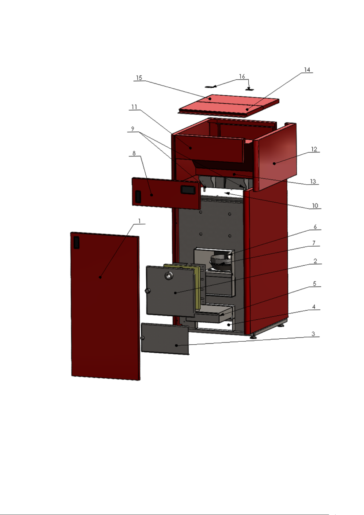
1.3 Boiler parts
Delovi kotla: 1. Boiler door (external) 2. Inner boiler door (including visor and insulation) 3. Inner door
for cleaning 4. Ash cleaning area of the tubulators 5. Ash-tray of the burner 6. Pellet doser 7. Embedded
pellet burner 8. Upper external door with display 9. Tubulator handels 10. Cover of tubulators handles 11.
Boiler housing-upper part 12. Boiler housing -lateral part 13. Pellet magazine 14. Pellet magazine cover mobile part 15. Pellet magazine cover - fixed part 16. Covering hinges
5
Page 7
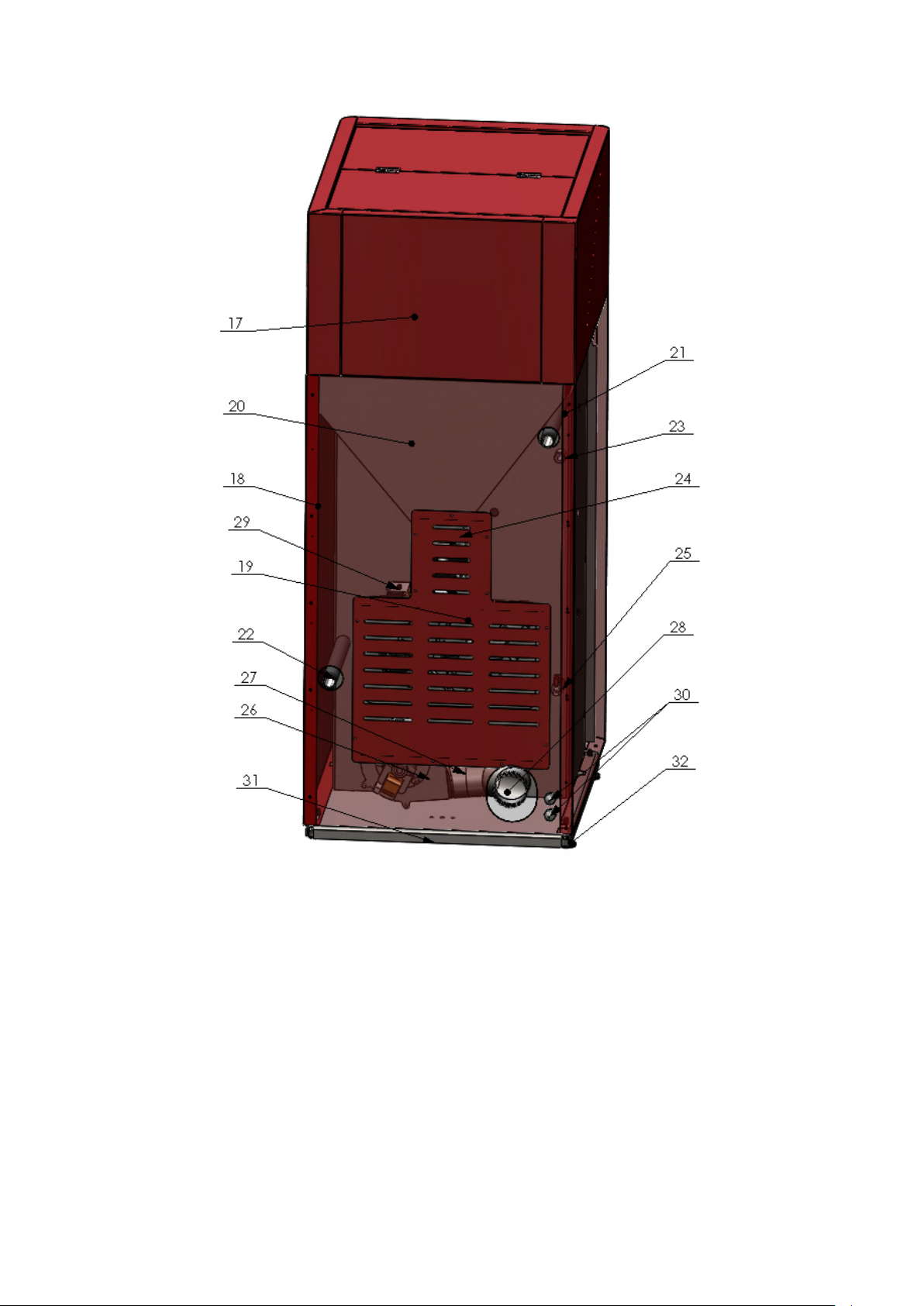
Delovi kotla posmatrano sa zadnje strane: 17. Back housing-upper part 18. Back housing 19. Back
revision opening lid 20. Small pellet magazine 21. Start line 22. Return line 23. Water probe 24. Spiral
dispenser with motor 25. Fill/drain tap 26. Boiler fan 27. Fumes probe 28. Flue line element 29. Spisal
dispenser probe 30. Electrical cable lead 31. Boiler basement 32. Boiler legs (adjustable)
6
Page 8
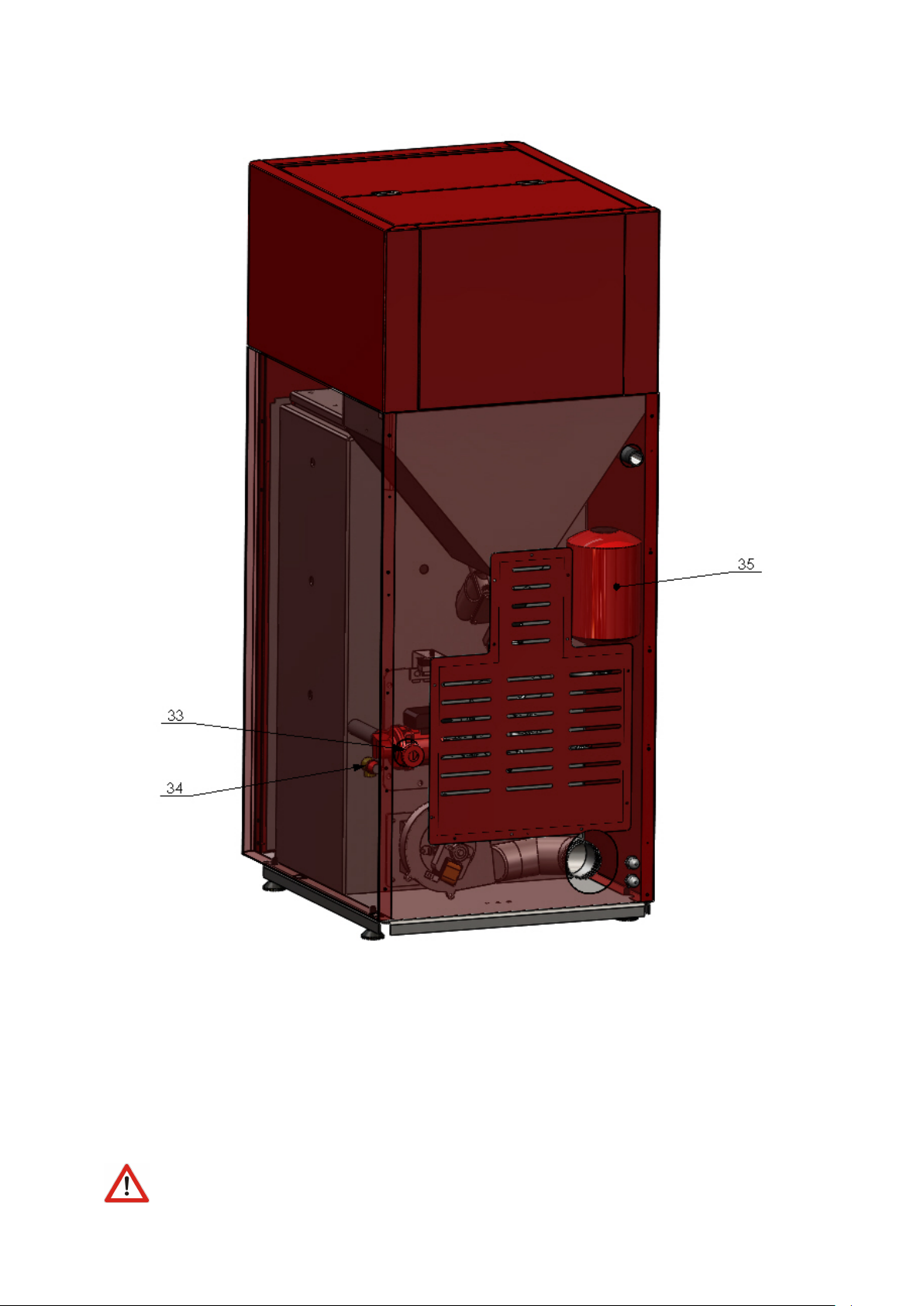
SET VERSION: 33. Circulation pump 34. Safety valve 35. Expansion vessel
2 Directions for storage and transport
2.1 Delivery form
Boiler is shipped with plastic protection sleeve on a europallet.
Boiler must be in its upright position all the time.
7
Page 9

The rotation of the boiler during the shipment or installation represents a serious risk and
can lead to damaging the boiler.
It is forbidden to place one boiler onto another.
The boiler can be stored only in closed rooms with no atmospheric influence. The humidity
in the storing room also must not exceed the critical value of 80%, so as not to create any condensate.
The temperature of the storing room must be in the range from 0 ˚C to 40 ˚C.
When unpacking the boiler, you must check whether the paint on the boiler coating has been
scratched somewhere and whether all parts of the boiler stand in their proper position.
2.2 Delivery range
Together with the boiler, also the following parts are supplied:
• Cleaning kit
• Warranty paper and this boiler manual
• Boiler regulation (built-in already)
• Tap valve (to be found below the housing on the return line)
• circulation pump, expansion vessel, safety valve
Along the boiler following parts are NOT INCLUDED:
• Thermomanometer
• Mixing valve
• Air vent or boiler valves
3 Introductory remarks
The end user must follow the guidelines from this manual all the time. In contrary case the
warranty won’t be acknowlidged.
Boiler chamber is tested on test pressure of 6 bar in our own facility.
Pay strict attention that boiler valves are always open while boiler in use.
Don’t forget to do a mechanical reset of the circulation pump at start of every heating season.
8
Page 10
Clean the boiler on a regular base.
An expert should be entrusted with the mounting of the heating and the initial operation.
This must be a person who will take over the responsibility and guarantee the correct operation of the
boiler and of the complete central heating system. In the case of an incorrectly planned system with
manifesting deficiencies caused by the respective person’s incorrect installation of the system, which can
again lead to an incorrect operation of the boiler, the complete liability for the material damage and
potential new costs arising in relation to it is borne exclusively by the person who was entrusted with
the mounting of the central heating system, and not by the boiler manufacturer, sales representative or
seller.
4 Safety remarks
While in use, some parts of the boiler may be hot. Don’t touch the boiler without appropriate
hand protection against heat.
If some parts of the boiler occur to be damaged it is strictly forbidden to continue using the
boiler.
Do not touch electrical wires with wet hands
Electric connections must be made according to 73/23 CEE i 93/98 CEE and properly dimensioned.
Use of the temperature relief valve is OBLIGATORY with this boiler to ensure safety in
heating systems using solid fuels.
5 Boiler placement
5.1 Boiler room
Room where kamin is placed, must posess ventilation windows.
9
Page 11
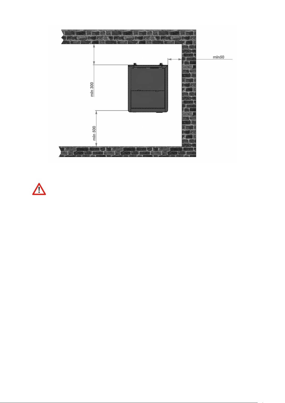
Front side should have free access.
Boiler base must be stable and made of fireproof material.
5.2 Connecting to the chimney
TOBY H kamin is a boiler with natural draught so it requires a chimney not just to transport flue gases
out of the boiler but also to create negative pressure necessary for boiler function.
Boiler requires pressure drop of 10 Pa.
Chimney is to be connected as depicted below and it is necessary to clean the chimney 1-2 per year.
10
Page 12

1) Flue pipe 2) Gasket 3) Fireproof protection cap 4) Chimeny dimater not greater than 200x200mm with
max height 5-6 metars.
5.3 Filling the system with water
Filling the system with water is to be done using the tap valve connection of the boiler.
When filling the system with water take care that no air remains in the boiler.
The filling process is done when no air is coming out through automatic air vent and pressure gauge is
showing the value between 1,5 and 2,5 bar (closed systems). Air vent is to be set at the highest point of
the (closed) central heating system. If the pressure is below 1,5 bar the filling process must be repeated.
For open systems, working pressure depends on the overall height of the system and the open expansion
vessel (1 bar for each 10 m is an estimate).
After the filling process is done, it is obligatory to close the drain tap valve, close the water supply to
the water-filling pipe and detach the water-filling pipe.
5.4 Connecting the boiler with a closed central heating system with circulation
pump on the return line
Recommended connection scheme is depicted below:
11
Page 13

1) Boiler TOBY B 2) Boiler valve 3) Automatic air vent 4) Termo-manometer 5) Safety valve 6) Mix valve
7) Expansion vessel 8) Circulation pump 9) Dirt catcher
The safety valve (with preset 2,5 bar threshold) should be mounted closed to the boiler (Po-
sition 5 at the image above).
It is essential to have a thermometer and a manometer installed to the system (Position 4 on
upper scheme)
It is recommended to install a dirt catcher and also an anticondensation valve on the return
line. (3-way mixing valve).
CLosed expansion vessel (position 7) should be mounted close to the boiler. Vessel must be
positioned so that its membrane is in horizontal position. he volume od the vessel is calculated using the
ratio 1 KW :1 l.
12
Page 14

5.5 Connecting the boiler with a closed central heating system with circulation
pump on the flow line
Recommended connection scheme is depicted below:
1) Boiler TOBY B 2) Boiler valve 3) Automatic air vent 4) Termo-manometer 5) Safety valve 6) Mix valve
7) Expansion vessel 8) Circulation pump 9) Dirt catcher
The safety valve (with preset 2,5 bar threshold) should be mounted closed to the boiler (Po-
sition 5 at the image above).
It is essential to have a thermometer and a manometer installed to the system (Position 4 on
upper scheme)
It is recommended to install a dirt catcher and also an anticondensation valve on the return
line. (3-way mixing valve).
CLosed expansion vessel (position 7) should be mounted close to the boiler. Vessel must be
positioned so that its membrane is in horizontal position. he volume od the vessel is calculated using the
13
Page 15
ratio 1 KW :1 l.
5.6 Connecting the boiler with a closed central heating system SET version
Recommended connection scheme is depicted below:
1) Boiler TOBY H 2) Boiler valve 3) Automatic air vent 4) Termo-manometer 5) Mix valve 6) Dirt catcher
The safety valve (with preset 2,5 bar threshold) is already mounted on the backside of the
boiler and its connected directly to the boiler water jacket (Position 18, drawing in Chapter 1)
Sigurnosni ventil (sa pragom otvaranja podešenim na 2,5 bar) je već montiran na samom
kazanu kotla (Poglavlje 1, Pozicija 18 na crtežu kotla).
It is essential to have a thermometer and a manometer installed to the system (Position 4 on
upper scheme)
14
Page 16

It is recommended to install a dirt catcher and also an anticondensation valve on the return
line. (3-way mixing valve).
Please not that air-vent is not premounted with the boiler. It should be connected externally.
5.7 Use of temperature relief valve with obligatory filling
The temperature relief valve (shown below) must be present in the system. The valve must
be installed by a qualified technician in accordance with the instructions given in the manual from the
producer of the valve. We recommend the CALEFFI 544501 valve depicted below.
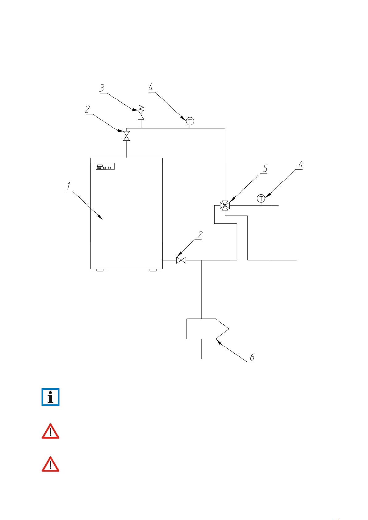
6 Return line protection against condensation
Every boiler is sensitive to condensation if the return line water temperature is too low. In order to avoid
it is necessary to mount the mixing valve to this boiler.
15
Page 17

1. 3-end mixing valve 2. Circulation pump 3. Thermostate
The purpose of this valve is to transmit a portion of the hot water to the return line cold water in
order to compensate the temperature difference between the flow and return line.
7 Boiler cleaning and maintenance
Regular maintenance and cleaning of pellet boilers is necessary to ensure product functionality and longlife operation.
Regular weekly cleaning consists of following operations (detailed steps are xplained in text below).
1. Emptying the ash from the bottom of the boiler (using the ash tray delivered with boiler)
2. Removing ash layers in the heating chamber if such
3. Cleaning the retort burner (round plate where pellets are falling in)
4. Cleaning the plate which is carrying the retort burner
5. Moving the bar in the heat exchanger of the boiler. This would force the ash to fall down from the
difficult-to-access heat exchangers area.
Occasional (seasonal) cleaning consists of regular weekly cleaning plus detailed cleaning of the heating
chamber from above.
How often do I need to clean the boiler? This depends on several factors, most important is the
quality and purity of the wood pellets used. Weekly cleaning has to be performed 1-2 per week, seasonal
cleaning 1-3 times during the heating season.
However if pellets of extremely bad quality are used, the cleaning frequency can change dramatically.
Boiler would not last long.
What tools do I need to clean the boiler? Simple cleaning set is delivered with the boiler. However,
ash-vacuum-cleaner would make things faster and easier.
Before performing any of the steps described below, boiler must be turned off and completely cold.
This is especially important for heat-exchanger cleaning. If they are still hot while bar is moved up and
down, they will be damaged.
It is obligatory to wear gloves for any operation described below.
7.1 Regular weekly cleaning
Necessary equipment: Gloves, Ash removing vacuum cleaner OR manual cleaning set (delivered with
boiler).
Open the outter main boiler door.
16
Page 18

Open the lower, chamber door with the boiler KEY.
Release the upper mobile part of the burner pot.
Attention: Some boiler parts may be hot!
Clean the area around the burner.
Clean the area around the burner. If you dont have
a ash vacuum cleaner, use the manual tools that are
delivered with the boiler.
17
Page 19

Burner is now free of ash.
Put the upper burner part back in place.
Release the screw-balls that hold the plate below.
Clean the area inside with the ash cleaner or using
manual tools. When screwing back the holders,
screw completely, so that no air can pass inside.
18
Page 20

If no vacuum cleaner is present, use the hand tools
as shown below.
19
Page 21

7.2 Weekly cleaning of the heat exchangers
Necessary equipment: Gloves, boiler KEY (delivered with the boiler).
Make sure you perform this operation while boiler is cold.
Open the doors on the top panel of the boiler.
There are two bars coming out.
Now take the boiler KEY, mount on the bar and
move up-down to release the ash from the heat
exchanger tubulators. Do this for both bars.
7.3 Occasional (seasonal) cleaning
Necessary equipment: Gloves, Ash removing vacuum cleaner OR manual cleaning set (delivered with
boiler). Boiler KEY (delivered with the boiler) or fork key 13.
Open the upper outter door of the boiler.
20
Page 22

Metal cap with tubulator lifters and one screw in
the middle is visible.
The insulation coat is attached below this metal
cap. To unsrew the cap use boiler KEY.
Put the metal cap aside.
make sure you make no damage to the stone-wall
insulation below.
21
Page 23

With fork-key size 13 or boiler KEY, unscrew the
upper cover of the heating chamber.
Lift the cover and put it on side.
Perform detailed cleaning of all parts that can be
accessed. Remove the ash.
The use of the ash-vacuum cleaner would make this
job faster and easier.
22
Page 24

After the cleaning put back the cover and screw the
holders.
Put everything back in its place.
Prhovačka bb 22310 Šimanovci, Srbija
Tel/Fax. +381 22 480404 +381 63 259422
podrska@termomont.rs www.termomont.rs
23
 Loading...