

Page 1

Compact size wood pellet boiler TOBY B 12-17-21
DIRECTIONS for use and maintenance
Prhovačka bb 22310 Šimanovci, Srbija
Tel/Fax. +381 22 480404 +381 63 259422
podrska@termomont.rs www.termomont.rs
December 13, 2016
Page 2

Contents
1 Basic Boiler data 2
1.1 Technical data according to EN 303-5 . . . . . . . . . . . . . . . . . . . . . . . . . . . . . 3
1.2 Product description . . . . . . . . . . . . . . . . . . . . . . . . . . . . . . . . . . . . . . . . 3
1.3 Boiler parts . . . . . . . . . . . . . . . . . . . . . . . . . . . . . . . . . . . . . . . . . . . . 4
1.4 Boiler parts - variation TOBY B 12 SET . . . . . . . . . . . . . . . . . . . . . . . . . . . . 6
2 Directions for storage and transport 6
2.1 Delivery form . . . . . . . . . . . . . . . . . . . . . . . . . . . . . . . . . . . . . . . . . . . 6
2.2 Delivery range . . . . . . . . . . . . . . . . . . . . . . . . . . . . . . . . . . . . . . . . . . . 7
3 Introductory remarks 7
4 Safety remarks 8
5 Boiler placement 8
5.1 Boiler room . . . . . . . . . . . . . . . . . . . . . . . . . . . . . . . . . . . . . . . . . . . . 8
5.2 Connection to the chimney . . . . . . . . . . . . . . . . . . . . . . . . . . . . . . . . . . . 9
5.3 Filling the system with water . . . . . . . . . . . . . . . . . . . . . . . . . . . . . . . . . . 10
5.4 Connecting the boiler with a closed central heating system . . . . . . . . . . . . . . . . . . 10
5.4.1 Installation method 1 . . . . . . . . . . . . . . . . . . . . . . . . . . . . . . . . . . 11
5.4.2 Installation method 2 . . . . . . . . . . . . . . . . . . . . . . . . . . . . . . . . . . 12
5.5 Use of temperature relief valve with obligatory filling . . . . . . . . . . . . . . . . . . . . . 13
5.6 Fitting the boiler to an open central heating system. . . . . . . . . . . . . . . . . . . . . . 13
6 Return line protection against condensation 15
6.1 Boiler cleaning and maintenance . . . . . . . . . . . . . . . . . . . . . . . . . . . . . . . . 16
6.2 Regular weekly cleaning . . . . . . . . . . . . . . . . . . . . . . . . . . . . . . . . . . . . . 16
6.3 Weekly cleaning of the heat exchangers . . . . . . . . . . . . . . . . . . . . . . . . . . . . . 19
6.4 Occasional (seasonal) cleaning . . . . . . . . . . . . . . . . . . . . . . . . . . . . . . . . . . 19
1
Page 3
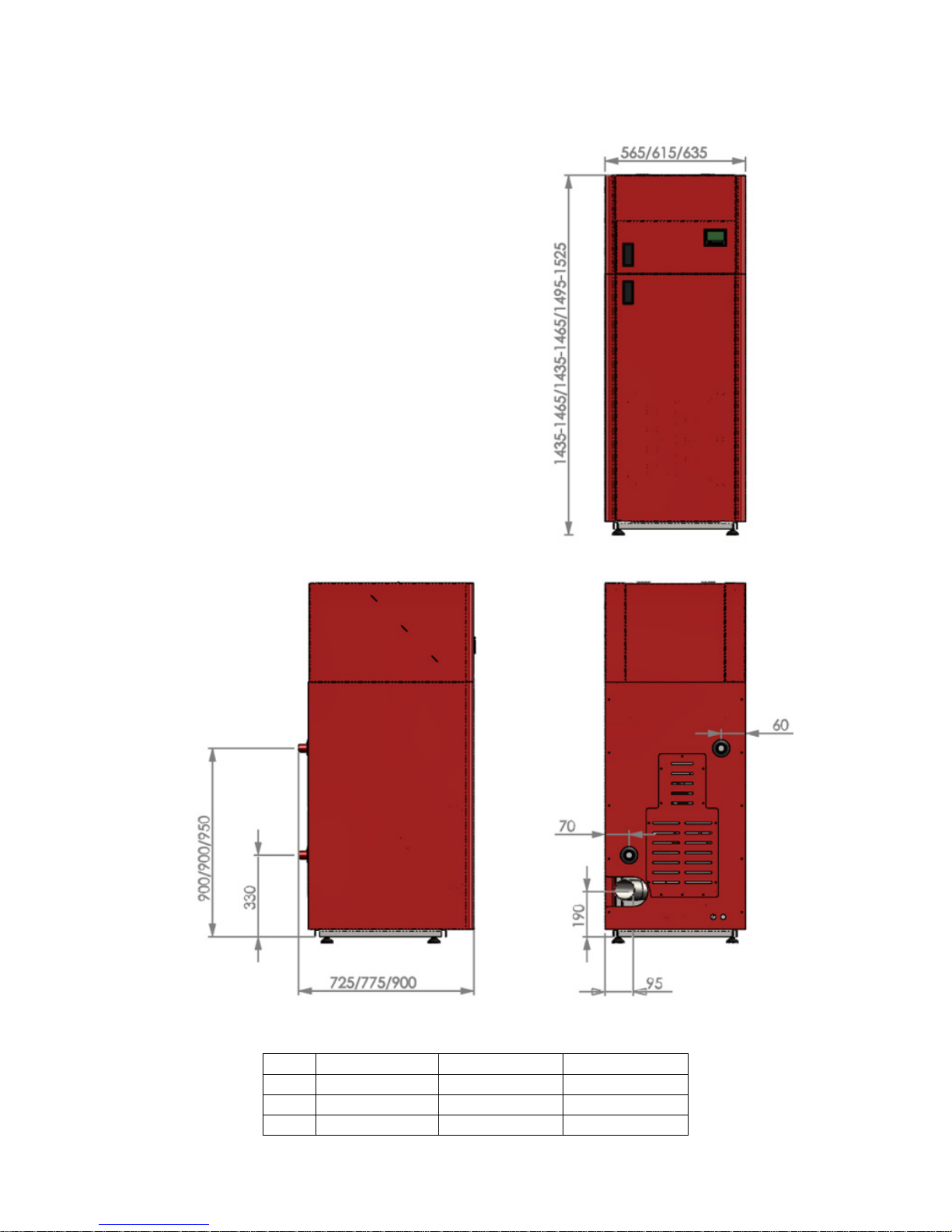
1 Basic Boiler data
Type Width B (mm) Height H (mm) Length L (mm)
B 12 565 1435/1465 725
B 17 615 1435/1465 775
B 20 635 1495/1525 900
2
Page 4

1.1 Technical data according to EN 303-5
Boiler type TOBY B 12 17 21
Total power 13.5 KW 17,5 KW 21 KW
Power range 3.6-13.5 KW 4.8 - 17.5 KW 6.3 - 20,7 KW
Min power pellet consumptioni min 0.8 kg/h min 1.1 kg/h min 1.4 kg/h
Max power pellet consumption max 2.8 kg/h max 3.7 kg/h max 4.6 kg/h
Width (mm) 565 615 635
Height (mm) 1435-1465 1435-1465 1495-1525
Depth (mm) 725 775 905
Flue gas exit height (mm) 190 190 190
Total weight of the boiler 190 kg 210 kg 265 kg
Pellet capacity 80 kg 90 kg 100 kg
Flow/Return (inch) 1" 1" 1
Fill/Drain Tap (inch) 1/2" 1/2" 1/2"
Flue gas exit diameter ((Φ )) 80 mm 80 mm 80 mm
Air inlet ((Φ )) 50 mm 50 mm 50 mm
Exit flue gas temperature 160◦C 160◦C 160◦C
Necessary draught 10 Pa 10 Pa 10 Pa
Boiler water volume 33 lit 41 lit 58 lit
Electric power supply 220 V 50 Hz 220 V 50 Hz 220 V 50 Hz
Energy consumption during start-up 400 W 400 W 400 W
Energy consumption during operation 100 W 100 W 100 W
Efficiency 90 % 90 % 90 %
Boiler class 5 5 5
1.2 Product description
• TOBY B boilers are aimed for residential buildings (up to 150 sqm) but unlike TOBY H kamin, B
models are exclusively aimed for boiler rooms. Sign B stays for „compact design“ of this boiler – it
is smaller and weights less than the standard “three-pass” TOBY 20 model.
• 12 KW models can also come in so-called „SET“ versions: SET means that circulation pump,
expansion vessel, safety valve are all included and pre-mounted into the boiler.
• With purchase of additional boiler router, regulation of this boiler can be connected with internet: boiler can be turned on/off directly from mobile phone through application (android and ios
supported so far).
• Boiler is completely adapted to burn wood pellet as a primary fuel, achieving maximum efficiency
level (90
• Ignition, start-up and turning-off are fully automatized. Combustion control is optimized using
algorithms such as ‘modulation’ which automatically decreases pellet dose as the difference between
desired and reached temperature is decreasing.
• Pellets are fed to boiler via internal transporter screw inside the storage tank. From there pellets
are fed over to heating chamber where they fall free to the designated melting area (the ‘actual’
embedded burner of the boiler). Storage and melting area are physically divided. There is a safety
thermostat to prevent back-fire.
• Maintenance and cleaning are reduced to a minimum compared to all solid fuel boilers – only once
a week, with a premium quality pellet and proper maintenance even less frequent.
• Boiler is equipped with a safety pressure sensor – as soon as the boiler door is open – boiler stops
feeding pellets.
3
Page 5
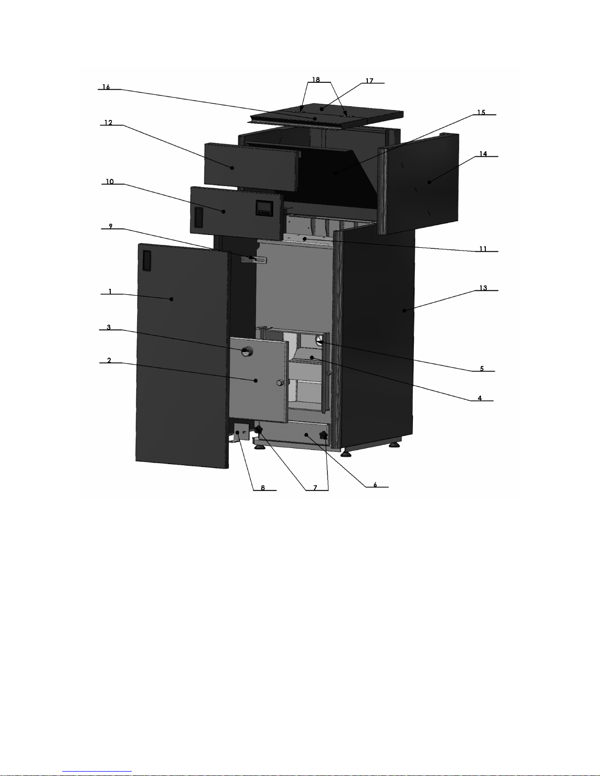
1.3 Boiler parts
1. Door housing plates 2. Outter door 3. Visor 4. Burner (pot) 5. Pellet doser tube 6. Opening for cleaning
7. Opening threads 8. Boiler housing (lower carrier) 9. Boiler housing (upper carrier) 10. Boiler small door
with display 11. Boiler Tubulators Opening 12. Boiler housing mask 13. Lateral sides of the housing
4
Page 6
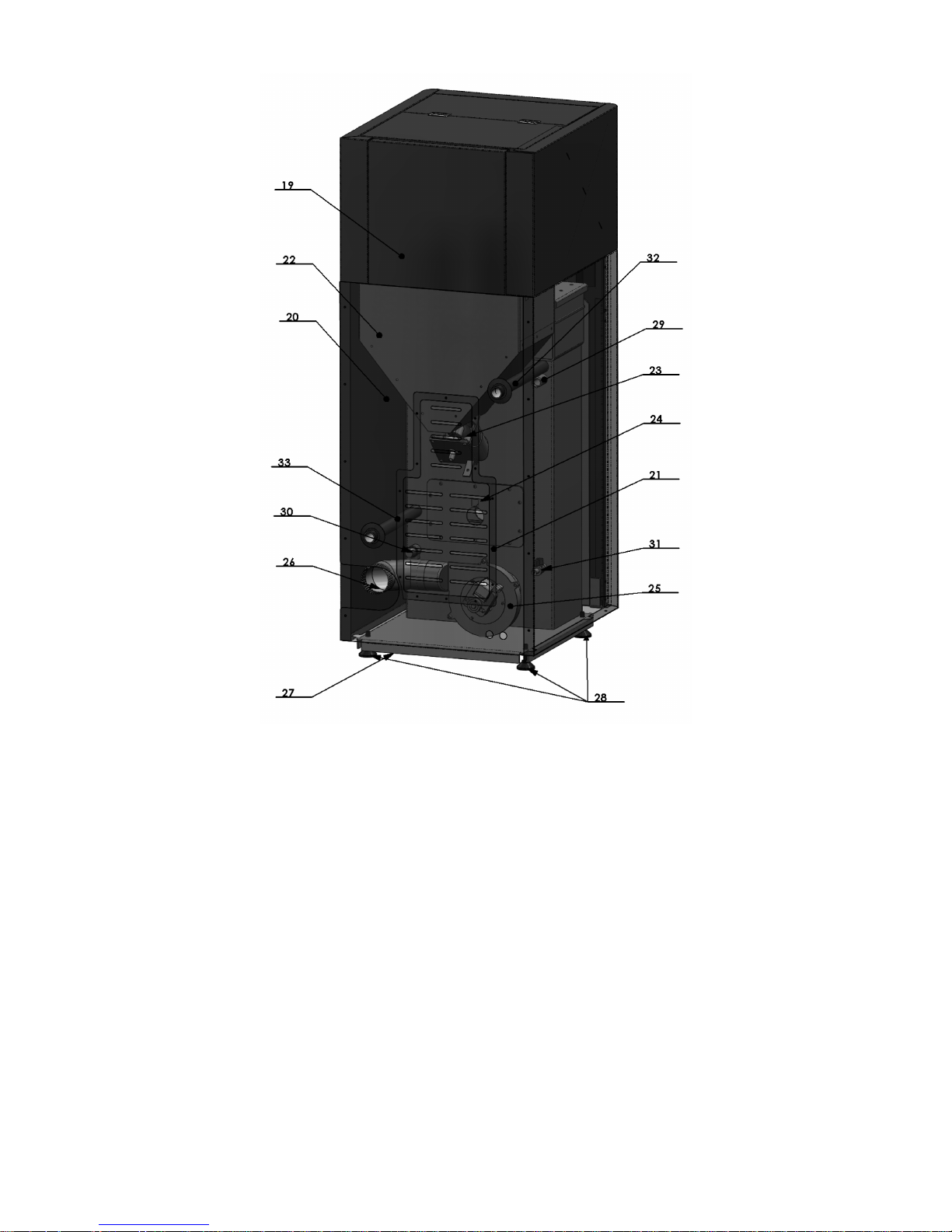
14. Upper lateral boiler housing plate 15. Pellet magazine slope 16. Hole for pellet flow 17. Fixed opening 18.
Opening hinges 19. Upper back housing plate 20. Back housing plate 21. Revision opening at back housing
plate 22. Small pellet magazine 23. Pellet auger with motor 24. Ignitor 25. Ventilator 26. Flue tube 27.
Basement 28. Adjustable legs 29. Probe 30. Safety valve 31. Fill / Drain Tap 32. Flow line 33. Return line
5
Page 7
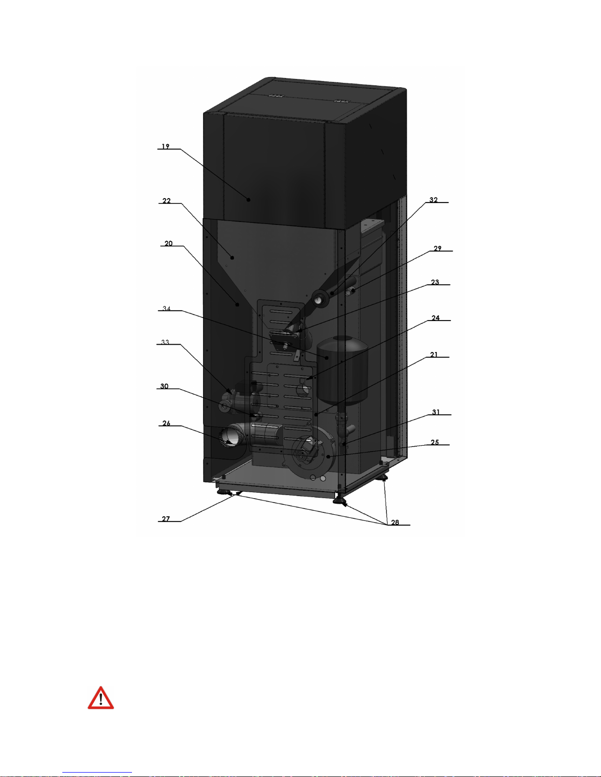
1.4 Boiler parts - variation TOBY B 12 SET
14. Upper lateral boiler housing plate 15. Pellet magazine slope 16. Hole for pellet flow 17. Fixed opening
18. Opening hinges 19. Upper back housing plate 20. Back housing plate 21. Revision opening at back
housing plate 22. Small pellet magazine 23. Pellet auger with motor 24. Ignitor 25. Ventilator 26. Flue tube
27. Basement 28. Adjustable legs 29. Probe 30. Safety valve 31. Fill / Drain Tap 32. Flow line 33. Return
Line with circulation pump 34. Expansion vessel
2 Directions for storage and transport
2.1 Delivery form
Boiler is shipped with plastic protection sleeve on a pallet.
Boiler must be in its upright position all the time.
6
Page 8

The rotation of the boiler during the shipment or installation represents a serious risk and
can lead to damaging the boiler.
It is forbidden to place one boiler onto another.
The boiler can be stored only in closed rooms with no atmospheric influence. The humidity
in the storing room also must not exceed the critical value of 80%, so as not to create any condensate.
The temperature of the storing room must be in the range from 0 ˚C to 40 ˚C.
When unpacking the boiler, you must check whether the paint on the boiler coating has been
scratched somewhere and whether all parts of the boiler stand in their proper position.
2.2 Delivery range
Together with the boiler, also the following parts are supplied:
• Cleaning kit with an ash tray
• Warranty paper and this boiler manual
• Boiler regulation (built-in already)
• Boiler cables to connect to power supply and circulation pump
• B 12 SET version ONLY: expansion vessel, circulation pump
Along the boiler following parts are OBLIGATORY but NOT INCLUDED in boiler delivery:
• Thermo-manometer and the safety group
• Mixing valve
• Boiler valves etc.
3 Introductory remarks
The end user must follow the guidelines from this manual all the time. In contrary case the
warranty won’t be acknowlidged.
Boiler chamber is tested on test pressure of 6 bar in our own facility.
Pay strict attention that boiler valves are always open while boiler in use.
Don’t forget to do a mechanical reset of the circulation pump at start of every heating season.
7
Page 9

Clean the boiler on a regular base.
An expert should be entrusted with the mounting of the heating and the initial operation.
This must be a person who will take over the responsibility and guarantee the correct operation of the
boiler and of the complete central heating system. In the case of an incorrectly planned system with
manifesting deficiencies caused by the respective person’s incorrect installation of the system, which can
again lead to an incorrect operation of the boiler, the complete liability for the material damage and
potential new costs arising in relation to it is borne exclusively by the person who was entrusted with
the mounting of the central heating system, and not by the boiler manufacturer, sales representative or
seller.
4 Safety remarks
While in use, some parts of the boiler may be hot. Don’t touch the boiler without appropriate
hand protection against heat.
If some parts of the boiler occur to be damaged it is strictly forbidden to continue using the
boiler.
Do not touch electrical wires with wet hands
Electric connections must be made according to 73/23 CEE i 93/98 CEE and properly dimensioned.
Use of the temperature relief valve is OBLIGATORY with this boiler to ensure safety in
heating systems using solid fuels.
5 Boiler placement
5.1 Boiler room
Boiler room must posess ventilation windows. The area for necessary ventilation surface is defined
like this:
A(cm2) = 6, 02 · P(KW )
where P is nominal boiler power KW.
8
Page 10

Front side and lateral side(s) should have free access. Otherwise, follow the measures depicted in the
drawing, since additional space is required to place the tube for flue gases behind the boiler.
Boiler base must be stable and made of fireproof material.
5.2 Connection to the chimney
Sub-pressure pellet boilers require pressure difference of at least 10 (± 3) Pa in order to ensure safe and
stable combustion process.
This boiler requires a vertical connection for the flue gases in accordance with European norms.
It is essential to regularly clean the chimney, at least few times a year.
9
Page 11

Legend: 1) Chimney 2) Gasket 3) Fireproof protection cap 4) Chimney diameter not greater than
200x200mm and not higher than 5-6m
5.3 Filling the system with water
Filling the system with water is to be done using the tap valve connection of the boiler.
When filling the system with water take care that no air remains in the boiler.
The filling process is done when no air is coming out through automatic air vent and pressure gauge is
showing the value between 1,5 and 2,5 bar (closed systems). Air vent is to be set at the highest point of
the (closed) central heating system. If the pressure is below 1,5 bar the filling process must be repeated.
For open systems, working pressure depends on the overall height of the system and the open expansion
vessel (1 bar for each 10 m is an estimate).
After the filling process is done, it is obligatory to close the drain tap valve, close the water supply to
the water-filling pipe and detach the water-filling pipe.
5.4 Connecting the boiler with a closed central heating system
The use of a safety valve is obligatory (with a 2-3 bar threshold, depending on the power of the
10
Page 12

boiler) and it must be mounted near the boiler.
It is essential to have a thermometer and a manometer installed to the system.
It is recommended to install an anticondensation valve on the return line. (3-way mixing valve).
It is also recommended to mount a filth catcher on the return line.
Depending on the position of the boiler in relation to the pipe-work and the radiators – the installation
can be carried out using one of two methods.
5.4.1 Installation metho d 1
If the boiler is positioned on the same level or higher than the pipe-work and radiators.
Each of the following items of equipment shall be fitted along the flow line:
1. Automatic air vent.
2. Safety valve (spring valve is recommended).
3. Expansion vessel.
4. Boiler valve.
The safety pressure valve must always be positioned and mounted close to the boiler. It
must be easily identifiable and allow for easy access. The safety pressure valve must be set to a nominal
pressure of 2.5 bar. The valve must open and operate smoothly at 2.5 bar. Diameter for the aperture
at the seat of the valve must be at least 15mm. Connecting pipework to the boiler must be as short
as possible. Welds, joints or any possible blockage to this pipe-work must be prevented. Bends in the
pipe-work should be avoided if possible. Unavoidable bends should be of a diameter r>3D (D = radius
of curvature) and less than α > 90 ˚C .
The closed expansion vessel shall be fitted close to the boiler. Connecting pipework should
be as short as possible. Fit the expansion vessel in horizontal alignment to the pipe to ensure equal
distribution of pressure. The volume of the expansion vessel is determined by the output/capacity of the
boiler. A ratio of 1 kW:1 litre should be used. The safety pressure valve and the expansion vessel should
be fitted in close proximity to each other, in the following order: expansion vessel closest to the boiler,
followed by the safety pressure valve.
In the event of power failure and the boiler fails to operate correctly – any sudden increase of
pressure will be controlled first by the expansion vessel, on any further increase in pressure the safety
pressure valve will open.
11
Page 13

5.4.2 Installation metho d 2
To be used in the case of the boiler being positioned and installed at a lower level than the installed
pipework and radiators.
As shown on Figure, following elements are connected along the FLOW:
1. Automatic air vent
2. Safety valve
3. Circulation pump (separated with ball valves on each side so that it can be easily replaced if
necessary).
Expansion vessel is on the RETURN line in this case.
Expansion vessel and safety valve are connected following the rules described in the previous
chapters. For safe operation info on additional equipment such as expansion vessel and safety valve please
refer to manuals delivered with those products.
12
Page 14

5.5 Use of temperature relief valve with obligatory filling
The temperature relief valve (shown below) must be present in the system. The valve must
be installed by a qualified technician in accordance with the instructions given in the manual from the
producer of the valve.
We recommend the CALEFFI 544501 valve depicted below.
5.6 Fitting the boiler to an open central heating system.
The connecting scheme of an open central heating system is depicted on the figure.
13
Page 15

When using open system on the FLOW line following elements are to be installed: safety
pipework for the open expansion vessel, boiler valve. On the RETURN line come safety return line of
the open expansion vessel, boiler valve and circulation pump valves.
Open expansion vessel is connected to the hot-water distribution pipes (FLOW and RETURN)
as shown on Figure – with an additional OVERFLOW pipe output plus CIRCULATION pipe (to prevent
freeze during winter months).
Please note that no additional items shall be connected to the open expansion vessel – espe-
cially not valves.
The size of expansion vessel is deducted from the following equation:
V = 0, 07V
water
(l)
V
water
(l) is the water volume in the entire installation. Diameter for the pipework of the expansion vessle
line should be round 25 mm.
Open expansion vessel is to be positioned vertically above the highest heating element.
14
Page 16

6 Return line protection against condensation
Every boiler is sensitive to condensation if the return line water temperature is too low. In order to avoid
it is necessary to mount the mixing valve to this boiler.
1. 3-end mixing valve 2. Flow line 3. Return line
The purpose of this valve is to transmit a portion of the hot water to the return line cold water in
order to compensate the temperature difference between the flow and return line.
15
Page 17

6.1 Boiler cleaning and maintenance
Regular maintenance and cleaning of pellet boilers is necessary to ensure product functionality and longlife operation.
1. Emptying ash-trailers of the boiler
2. Removing ash from the bottom part of the boiler chamber
3. Cleaning of burner pot
4. Cleaning of the holder of burner pot
5. Moving the bar in the heat exchanger of the boiler. This would force the ash to fall down from the
difficult-to-access heat exchangers area.
Occasional (seasonal) cleaning consists of regular weekly cleaning plus detailed cleaning of the heating
chamber from above
How often do I need to clean the boiler? This depends on several factors, most important is the
quality and purity of the wood pellets used. Weekly cleaning has to be performed 1-2 per week, seasonal
cleaning 1-3 times during the heating season.
However if pellets of extremely bad quality are used, the cleaning frequency can change dramatically.
Boiler would not last long.
What tools do I need to clean the boiler? Simple cleaning set is delivered with the boiler. However,
ash-vacuum-cleaner would make things faster and easier.
Before performing any of the steps described below, boiler must be turned off and completely
cold. This is especially important for heat-exchanger cleaning. If they are still hot while bar is moved up
and down, they will be damaged.
It is obligatory to wear gloves for any operation described below.
6.2 Regular weekly cleaning
Necessary equipment: Gloves, Ash removing vacuum cleaner OR manual cleaning set (delivered with
boiler).
Open the outter main boiler door.
16
Page 18

Open the lower, chamber door with the boiler KEY.
Open the main boiler door and remove the ash-tray
outside the boiler.
Also remove burner pot, remove the ash from the
pot int the ash-tray first, then empty the ash-tray.
CAUTION: SOME PARTS MAY BE HOT!
Clean the area where burner pot is placed. Dont
forget to clean the top of the tube where resistance
heater is placed. When putting parts back to its
place make sure the position is the same as before.
Otherwise, boiler will not operate properly.
17
Page 19

If no vacuum cleaner is present, use the hand tools
as shown below.
Release the screw-balls that hold the plate below.
Clean the area inside with the ash cleaner or using
manual tools. When screwing back the holders,
screw completely, so that no air can pass inside.
Ukoliko ne posedujetevIf no vacuum cleaner is
present, use the hand tools as shown below.
18
Page 20

6.3 Weekly cleaning of the heat exchangers
Necessary equipment: Gloves, boiler KEY (delivered with the boiler).
Make sure you perform this operation while boiler is cold.
Open the doors on the top panel of the boiler.
There are two bars coming out.
Now take the boiler KEY, mount on the bar and
move up-down to release the ash from the heat
exchanger tubulators. Do this for both bars.
6.4 Occasional (seasonal) cleaning
Necessary equipment: Gloves, Ash removing vacuum cleaner OR manual cleaning set (delivered with
boiler). Boiler KEY (delivered with the boiler) or fork key 13.
Open the upper outter door of the boiler.
19
Page 21

Metal cap with tubulator lifters and one screw in
the middle is visible.
The insulation coat is attached below this metal
cap. To unsrew the cap use boiler KEY.
Put the metal cap aside.
make sure you make no damage to the stone-wall
insulation below.
20
Page 22

With fork-key size 13 or boiler KEY, unscrew the
upper cover of the heating chamber.
Lift the cover and put it on side.
Perform detailed cleaning of all parts that can be
accessed. Remove the ash.
The use of the ash-vacuum cleaner would make this
job faster and easier.
21
Page 23

After the cleaning put back the cover and screw the
holders.
Put everything back in its place.
22
 Loading...