

Page 1
Wood pellets boiler TOBY 20-30-40-50 KW
DIRECTIONS for use and maintenance
Prhovačka bb 22310 Šimanovci, Srbija
Tel/Fax. +381 22 480404 +381 63 259422
podrska@termomont.rs www.termomont.rs
November 15, 2016
Page 2

Contents
1 Boiler data 2
1.1 Technical data chart according to EN 303-5 . . . . . . . . . . . . . . . . . . . . . . . . . . 5
1.2 On Product . . . . . . . . . . . . . . . . . . . . . . . . . . . . . . . . . . . . . . . . . . . . 5
2 Directions for storage and transport 6
2.1 Delivery form . . . . . . . . . . . . . . . . . . . . . . . . . . . . . . . . . . . . . . . . . . . 6
2.2 Delivery range . . . . . . . . . . . . . . . . . . . . . . . . . . . . . . . . . . . . . . . . . . . 6
3 Introductory remarks 7
4 Safety remarks 7
5 Boiler placement 8
5.1 Boiler room . . . . . . . . . . . . . . . . . . . . . . . . . . . . . . . . . . . . . . . . . . . . 8
5.2 Chimney . . . . . . . . . . . . . . . . . . . . . . . . . . . . . . . . . . . . . . . . . . . . . . 8
5.3 Filling the system with water . . . . . . . . . . . . . . . . . . . . . . . . . . . . . . . . . . 9
5.4 Connecting the boiler with a closed central heating system . . . . . . . . . . . . . . . . . . 10
5.4.1 Installation method 1 . . . . . . . . . . . . . . . . . . . . . . . . . . . . . . . . . . 10
5.4.2 Installation method 2 . . . . . . . . . . . . . . . . . . . . . . . . . . . . . . . . . . 11
5.5 Use of temperature relief valve with obligatory filling . . . . . . . . . . . . . . . . . . . . . 12
5.6 Fitting the boiler to an open central heating system. . . . . . . . . . . . . . . . . . . . . . 12
6 Mixing valve 13
7 Control panel 14
7.1 Boiler cleaning and maintenance . . . . . . . . . . . . . . . . . . . . . . . . . . . . . . . . 15
A Emissions Test Report 19
1
Page 3
1 Boiler data
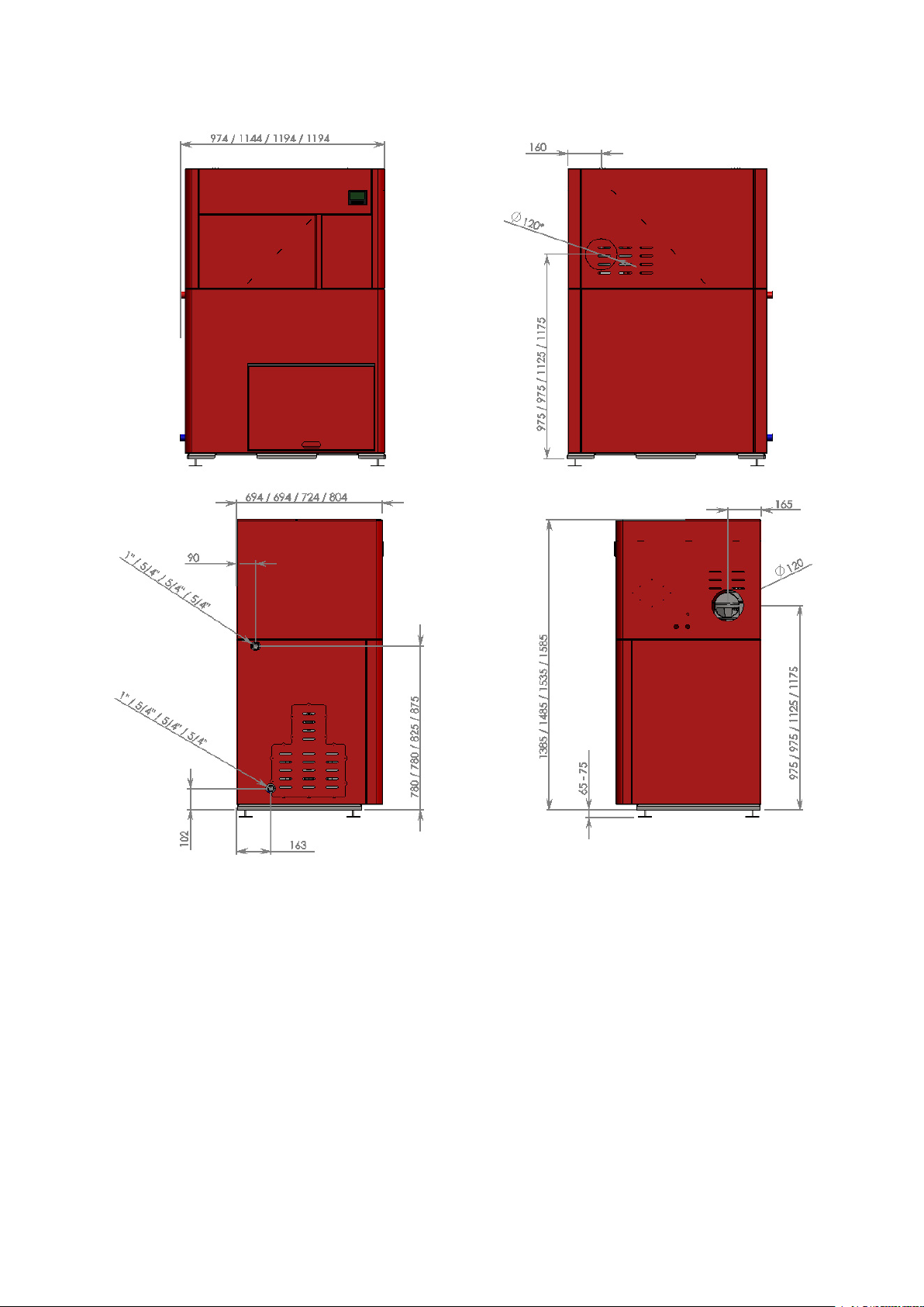
Boiler measures are given in the form X / Y / Z where first value is for the 20 KW model and second
value for 30 KW and third value for a 50 KW model where measures differ. Single measure is shown
elsewhere valid for all the models.
Boiler connections to the central heating system are on its left hand side. Flow line is painted red.
Return line is painted blue. Fill/Drain tap is located at the return line.
Flue gas exit is located on the right hand side of the boiler. It can be also on the back side of the boiler.
2
Page 4
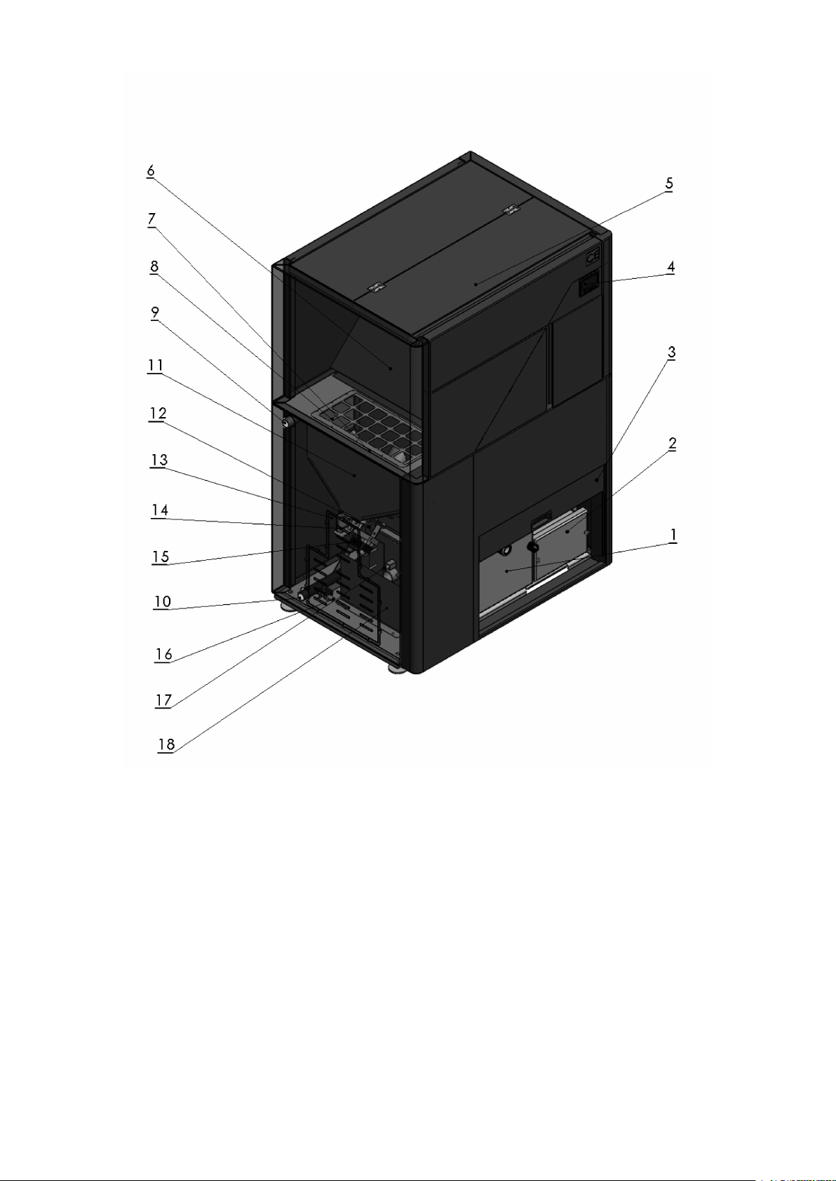
Boiler parts 1. Bigger front door (allows access to clean the burner) 2. Smaller front door (allows access
to clean the part below the heat exchanger, see combustion chamber figure below!) 3. External sliding door
4. Control panel 5. Pellet storage opening for refill (when there is no pellets, refill here!) 6. Pellet storage,
bigger unit 7. Bridge from bigger to smaller pellet unit 8. Protection grid 9. Flow line 10. Return line 11.
Pellet storage, smaller unit fed from the bigger unit 12. Safety thermostat (back-fire prevention) 13. Technical
opening to access the motor or the fill/drain tap 14. Pressure sensor (when the door is open boiler will stop
feeding automatically) 15. Internal feeding screw motor 16. Fill/Drain tap (dont forget to close this connection
once filling is completed) 17. Resistance heater (necessary for boiler start-up) 18. Protection plate
3
Page 5
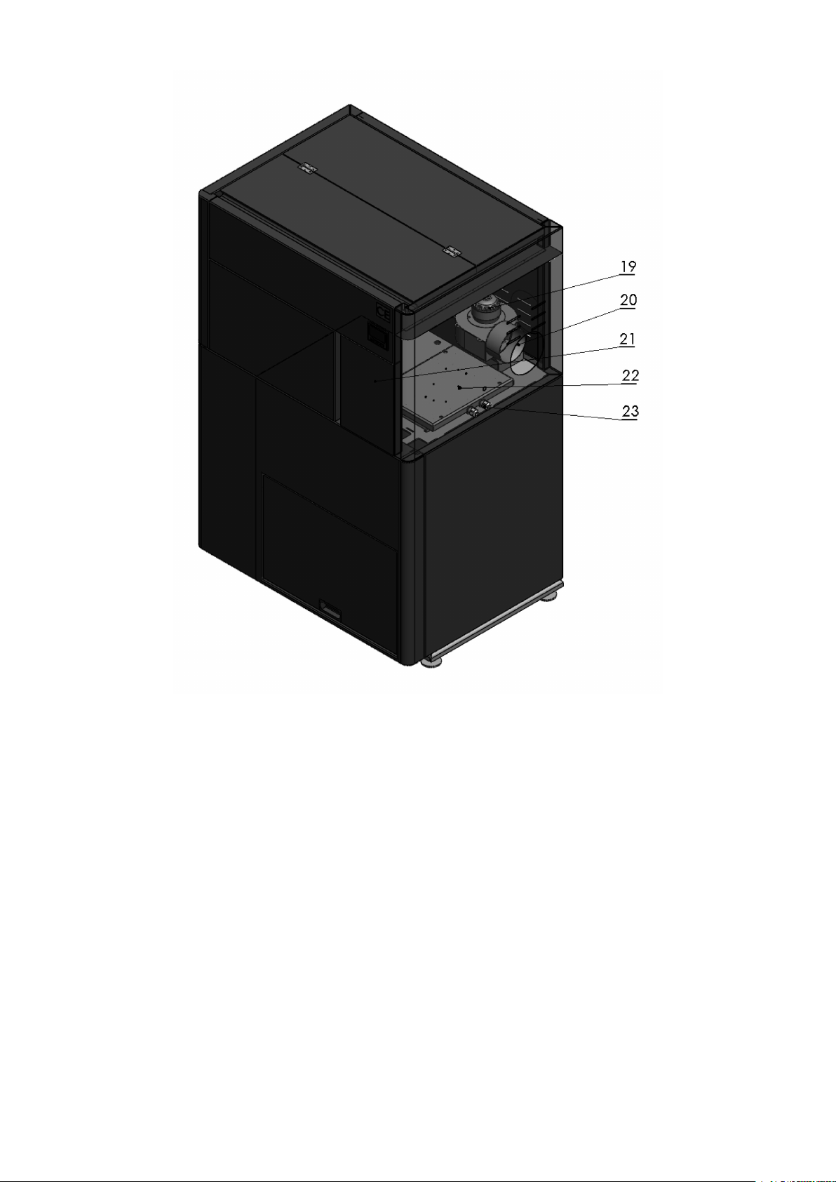
Boiler parts on the right side 19. Fan 20. Flue gas exit 21. Door to access the regulation board or the
fan (authorized person only) 22. Heat exchanger cover (access allowed only to authorized service persons) covered by insulation layer 23. Hole for cables
4
Page 6

1.1 Technical data chart according to EN 303-5
Boiler type TOBY TOBY 20 TOBY 30 TOBY 40 TOBY 50
Nominal power TOBY 24.7 KW 31.7 KW 40 KW 50 KW
Power range 5 - 24.7 KW 9.5 - 31,7 KW 13 - 39,9 KW 16 - 50 KW
Boiler weight 298 kg 338 kg 398 kg 470 kg
Flow/Return (inch) 1” 5/4” 5/4" 5/4"
Fill/Drain Tap (inch) 1/2" 1/2" 1/2" 1/2"
Flue gas output diameter ((Φ )) 120 mm 120 mm 120 mm 120 mm
Output gas temperature at nominal heat output
Storage capacity 120 kg 150 kg 180 kg 200 kg
Pellet consumption at min power min 1 kg/h min 2.18 kg/h min 2.7 kg/h min 3.2 kg/h
Pellet consumption at max power max 4.9 kg/h max 7.1 kg/h max 8.8 kg/h max 10 kg/h
Necessary draught 10 Pa 14 Pa 15 Pa 16 Pa
Water volume 62 lit 80 lit 98 lit 114 lit
Electrical network 220 V 50 Hz 220 V 50 Hz 220 V 50 Hz 220 V 50 Hz
Energy consumption during
start-up
Energy consumption in operation 100 W 100 W 100 W 100 W
Efficiency toward boiler water 90 % 90 % 90 % 90 %
Efficiency toward flue gases 93 % 93.5 % 92 %
Boiler class 5 5 5 5
160◦C 160◦C 160◦C 160◦C
400 W 400 W 400 W 400 W
Additional information for TOBY 30 according to EN 303-5 (obtained during laboratory testing):
Exhaust mass flow at nominal power: 15.6g/s ; at minimal power: 7.7g/s.
1.2 On Product
• TOBY represents one of the most sophisticated solutions for automatic combustion of wood pellets
to be found on the market.
• It is completely adapted to burn wood pellet as a primary fuel, achieving maximum efficiency level
up to 94% and a very low exit temperature for flue gases (below 160◦C).
• Emission levels of this boiler fulfill the most rigorous norms of European countries. TOBY 30 is
officially tested as a Class 5 boiler according to EN 303-5 at KiWa Institute in Treviso Italy and is
eligible for subventions and grants available in most EU countries.
• Ignition, start-up and turning-off are fully automatized. Combustion control is optimized using
algorithms such as ‘modulation’ which automatically decreases pellet dose as the difference between
desired and reached temperature is decreasing.
• Working principle of this boiler is based on the “sub-pressure” of the heating chamber. The chamber
is completely air-proof so that air flow in the boiler is fully controlled by the exhausting fan mounted
on the back. Boiler regulation completely controls the quantity of the air inside the heating chamber:
optimum combustion comes as a result.
• Boiler chamber is made by welding 5mm thick steel plates (all surfaces in touch with fire). Other
parts are made of 4mm steel.
• The efficiency of this boiler is much higher than that of the conventional boilers with natural air
flow.
• Pellets are fed to boiler via internal transporter screw inside the storage tank. From there pellets
are fed over to heating chamber where they fall free to the designated melting area (the ’actual’
embedded burner of the boiler). Storage and melting area are physically divided. There is a
safety thermostat to prevent back-fire. There is also a pressure sensor inside the heating chamber
5
Page 7

- when the boiler door is open, this sensor will react and stop the feeding process. There is also an
anti-explosion safety door on the side of the heating chamber.
• Maintenance and cleaning are reduced to a minimum compared to all solid fuel boilers – only once
a week, if not less than that, with a premium quality pellet and proper use. Please note the handle
on the front side of the boiler. This is designated for occasional cleaning of the heat exchanger of
the boiler (forcing the ash to fall down to te bottom of the boiler).
2 Directions for storage and transport
2.1 Delivery form
Boiler is shipped with plastic protection sleeve on a europallet.
Boiler must be in its upright position all the time.
The rotation of the boiler during the shipment or installation represents a serious risk and
can lead to damaging the boiler.
It is forbidden to place one boiler onto another.
The boiler can be stored only in closed rooms with no atmospheric influence. The humidity
in the storing room also must not exceed the critical value of 80%, so as not to create any condensate.
The temperature of the storing room must be in the range from 0 ˚C to 40 ˚C.
When unpacking the boiler, you must check whether the paint on the boiler coating has been
scratched somewhere and whether all parts of the boiler stand in their proper position.
2.2 Delivery range
Together with the boiler, also the following parts are supplied:
• Cleaning kit with an external ash tray
• Warranty paper and this boiler manual
• Boiler regulation (built-in already)
• Tap valve (to be found below the housing on the return line)
• Boiler cables to connect to power supply and circulation pump
Along the boiler following parts are NOT INCLUDED:
• Thermo-manometer and the safety group
• Mixing valve
• Boiler valves etc.
6
Page 8

3 Introductory remarks
The end user must follow the guidelines from this manual all the time. In contrary case the
warranty won’t be acknowlidged.
Boiler chamber is tested on test pressure of 6 bar in our own facility.
Pay strict attention that boiler valves are always open while boiler in use.
Don’t forget to do a mechanical reset of the circulation pump at start of every heating season.
Clean the boiler on a regular base.
An expert should be entrusted with the mounting of the heating and the initial operation.
This must be a person who will take over the responsibility and guarantee the correct operation of the
boiler and of the complete central heating system. In the case of an incorrectly planned system with
manifesting deficiencies caused by the respective person’s incorrect installation of the system, which can
again lead to an incorrect operation of the boiler, the complete liability for the material damage and
potential new costs arising in relation to it is borne exclusively by the person who was entrusted with
the mounting of the central heating system, and not by the boiler manufacturer, sales representative or
seller.
4 Safety remarks
While in use, some parts of the boiler may be hot. Don’t touch the boiler without appropriate
hand protection against heat.
If some parts of the boiler occur to be damaged it is strictly forbidden to continue using the
boiler.
Do not touch electrical wires with wet hands
Electric connections must be made according to 73/23 CEE i 93/98 CEE and properly dimensioned.
Use of the temperature relief valve is OBLIGATORY with this boiler to ensure safety in
heating systems using solid fuels.
7
Page 9

5 Boiler placement
5.1 Boiler room
Boiler room must posess ventilation windows. The area for necessary ventilation surface is defined
like this:
A(cm2) = 6, 02 · P (KW )
where P is nominal boiler power KW.
TOBY was designed to occupy minimum space. Connections for flue and water lines are on
lateral sides of the boiler allowing the boiler to be leaned on wall almost completely.
Front side and lateral side(s) should have free access. In case that flue gas exit can be put directly
through the wall on the right-hand side, you can lean the boiler completely to the back and/or to the
right. Otherwise, follow the measures depicted in the drawing, since additional space is required to place
the tube for flue gases behind the boiler.
Boiler base must be stable and made of fireproof material.
5.2 Chimney
Sub-pressure pellet boilers require pressure difference of at least 10 (± 3) Pa in order to ensure safe and
stable combustion process.
This boiler requires a vertical connection for the flue gases in accordance with European norms.
It is essential to regularly clean the chimney, at least few times a year.
8
Page 10

Legend: 1) Chimney 2) Gasket 3) Fireproof protection cap 4) Chimney diameter not greater than
200x200mm and not higher than 5-6m
5.3 Filling the system with water
Filling the system with water is to be done using the tap valve connection of the boiler.
When filling the system with water take care that no air remains in the boiler.
The filling process is done when no air is coming out through automatic air vent and pressure gauge is
showing the value between 1,5 and 2,5 bar (closed systems). Air vent is to be set at the highest point of
the (closed) central heating system. If the pressure is below 1,5 bar the filling process must be repeated.
For open systems, working pressure depends on the overall height of the system and the open expansion
vessel (1 bar for each 10 m is an estimate).
After the filling process is done, it is obligatory to close the drain tap valve, close the water supply to
the water-filling pipe and detach the water-filling pipe.
9
Page 11

5.4 Connecting the boiler with a closed central heating system
The use of a safety valve is obligatory (with a 2-3 bar threshold, depending on the power of the
boiler) and it must be mounted near the boiler.
It is essential to have a thermometer and a manometer installed to the system.
It is recommended to install an anticondensation valve on the return line. (3-way mixing valve).
It is also recommended to mount a filth catcher on the return line.
Depending on the position of the boiler in relation to the pipe-work and the radiators – the installation
can be carried out using one of two methods.
5.4.1 Installation method 1
If the boiler is positioned on the same level or higher than the pipe-work and radiators.
Each of the following items of equipment shall be fitted along the flow line:
1. Automatic air vent.
2. Safety valve (spring valve is recommended).
3. Expansion vessel.
4. Boiler valve.
The safety pressure valve must always be positioned and mounted close to the boiler. It
must be easily identifiable and allow for easy access. The safety pressure valve must be set to a nominal
pressure of 2.5 bar. The valve must open and operate smoothly at 2.5 bar. Diameter for the aperture
at the seat of the valve must be at least 15mm. Connecting pipework to the boiler must be as short
as possible. Welds, joints or any possible blockage to this pipe-work must be prevented. Bends in the
pipe-work should be avoided if possible. Unavoidable bends should be of a diameter r>3D (D = radius
of curvature) and less than α > 90 ˚C .
The closed expansion vessel shall be fitted close to the boiler. Connecting pipework should
be as short as possible. Fit the expansion vessel in horizontal alignment to the pipe to ensure equal
distribution of pressure. The volume of the expansion vessel is determined by the output/capacity of the
boiler. A ratio of 1 kW:1 litre should be used. The safety pressure valve and the expansion vessel should
be fitted in close proximity to each other, in the following order: expansion vessel closest to the boiler,
followed by the safety pressure valve.
In the event of power failure and the boiler fails to operate correctly – any sudden increase of
pressure will be controlled first by the expansion vessel, on any further increase in pressure the safety
pressure valve will open.
10
Page 12

5.4.2 Installation method 2
To be used in the case of the boiler being positioned and installed at a lower level than the installed
pipework and radiators.
As shown on Figure, following elements are connected along the FLOW:
1. Automatic air vent
2. Safety valve
3. Circulation pump (separated with ball valves on each side so that it can be easily replaced if
necessary).
Expansion vessel is on the RETURN line in this case.
Expansion vessel and safety valve are connected following the rules described in the previous
chapters. For safe operation info on additional equipment such as expansion vessel and safety valve please
refer to manuals delivered with those products.
11
Page 13

5.5 Use of temperature relief valve with obligatory filling
The temperature relief valve (shown below) must be present in the system. The valve must
be installed by a qualified technician in accordance with the instructions given in the manual from the
producer of the valve.
We recommend the CALEFFI 544501 valve depicted below.
5.6 Fitting the boiler to an open central heating system.
The connecting scheme of an open central heating system is depicted on the figure.
12
Page 14

When using open system on the FLOW line following elements are to be installed: safety
pipework for the open expansion vessel, boiler valve. On the RETURN line come safety return line of
the open expansion vessel, boiler valve and circulation pump valves.
Open expansion vessel is connected to the hot-water distribution pipes (FLOW and RETURN)
as shown on Figure – with an additional OVERFLOW pipe output plus CIRCULATION pipe (to prevent
freeze during winter months).
Please note that no additional items shall be connected to the open expansion vessel – espe-
cially not valves.
The size of expansion vessel is deducted from the following equation:
V = 0, 07V
V
(l) is the water volume in the entire installation. Diameter for the pipework of the expansion vessle
water
water
(l)
line should be round 25 mm.
Open expansion vessel is to be positioned vertically above the highest heating element.
6 Mixing valve
The use of a mixing valve unit mounted on the return line of the boiler is OBLIGATORY.
13
Page 15

1. Mixing valve 2. FLow line 3. Return line
The purpose of the mixing valve is to raise the low temperature of the return line water which could
harm the boiler body.
7 Control panel
There is a user-friendly touch screen controller on the front side of the boiler.
Manual on the regulaiton of the boiler is attached to this manual as a separate document to be
delivered with the boiler.
14
Page 16

7.1 Boiler cleaning and maintenance
Pellet combustion means total combustion in this case. Little ash remains in the boiler. It is necessary to
clean the boiler only once, maybe twice a week. Detailed cleaning once in a month and when the heating
period is over. Regular maintenance of the boiler means:
With every cleaning, pull the handle up and down on the front side of the boiler. This is to force the
ash to fall dawn from the vertical tube heat exchanger into lower part of the boiler.
1. Emptying the ash from the bottom of the boiler (using the ash tray delivered with boiler)
2. Removing ash layers in the heating chamber if such
3. Cleaning the retort burner (round plate where pellets are falling in)
4. Cleaning the plate which is carrying the retort burner
The cleaning procedure is exactly described in the following images.
Before cleaning, make sure that boiler is turned off, and that all its parts are cool. Hand
gloves are to be used to access boiler parts.
Along the boiler special tool-kit is delivered
to access boiler doors and move the turbulators inside the boiler body.
Open the left boiler door with a tool-kit key.
15
Page 17

to be cleaned from ash completely.
inside the boiler heating chamber.
Take the pot out from the boiler. The pot is
Also remove the ash from the pot basement
with other tools delivered with the boiler.
Remove the ash from the bottom of the boiler
16
Page 18

When putting back the pot please make sure
that opening for the resistance heater is on its left side and place the pot in its correct position.
Enusre that the pot is sitting correctly, make
sure the resistance heater is in its exact position it was before. Now make sure boiler door is tightly
closed, and with the same tool-kit key only the other side, open the right door.
right side.
Now dismount the smaller boiler door on the
17
Page 19

Remove the ash from the bottom.
Iti is necessary to move a little bit the boiler
turbulators, so that ash could drop down. Turbulators are flat-steel spiral pieces placed inside the heat
exchanger of the heating chamber. They are responsible for the high efficiency of the boiler, but they
also gather ash so it is necessary to force the ash to fall down. This is achieved by moving the boiler
handle a little bit on both sides. Use the same tool-kit key and mount it on the handle and move a little
bit several times.
Regular maintenenace will make your boiler last longer.
If bad quality pellet is used, with additions such as earth, dust, sand, silicate layer will show
up in the boiler preventing the normal function of the boiler.
If dirty parts are not removed, boiler will start to decay very fast.
This boiler is aimed only for 100% wood pellets.
18
Page 20

A Emissions Test Report
Following test report confirms low emissions values of TOBY boiler (within prescribed range of a class 5
boiler according to EN 303/5:2012)
19
 Loading...