

Termomont TKK3 max Series, TKK3 max 200, TKK3 max 250, TKK3 max 300, TKK3 max 100 Instruction Manual
...Page 1
Solid fuel hot water boiler TKK3 max 100-300 KW
INSTRUCTIONS MANUAL for usage and maintenance
Prhovacka bb 22310 Simanovci, Srbija
Tel/Fax. +381 22 480404 +381 63 259422
office@termomont.rs www.termomont.rs
September 9, 2013
Page 2

Contents
1 Boiler design 2
1.1 Dimensions . . . . . . . . . . . . . . . . . . . . . . . . . . . . . . . . . . . . . . . . . . . . 2
1.2 Technical data chart according to EN 303-5 . . . . . . . . . . . . . . . . . . . . . . . . . . 2
1.3 Maximum Wood Log Size . . . . . . . . . . . . . . . . . . . . . . . . . . . . . . . . . . . . 3
1.4 On Product . . . . . . . . . . . . . . . . . . . . . . . . . . . . . . . . . . . . . . . . . . . . 3
2 Recommendations for boiler shipment and storage 4
2.1 Delivery form . . . . . . . . . . . . . . . . . . . . . . . . . . . . . . . . . . . . . . . . . . . 4
2.2 What’s in the box . . . . . . . . . . . . . . . . . . . . . . . . . . . . . . . . . . . . . . . . 4
3 Boiler installation 4
3.1 Boiler placement . . . . . . . . . . . . . . . . . . . . . . . . . . . . . . . . . . . . . . . . . 4
3.2 Chimney . . . . . . . . . . . . . . . . . . . . . . . . . . . . . . . . . . . . . . . . . . . . . . 4
4 Boiler installation 5
4.1 Fitting the boiler to a closed central heating system . . . . . . . . . . . . . . . . . . . . . 5
4.1.1 Installation method 1 . . . . . . . . . . . . . . . . . . . . . . . . . . . . . . . . . . 5
4.1.2 Installation method 2 . . . . . . . . . . . . . . . . . . . . . . . . . . . . . . . . . . 7
4.2 Fitting the boiler to an open central heating system. . . . . . . . . . . . . . . . . . . . . . 7
4.3 Filling up the boiler and installation with water . . . . . . . . . . . . . . . . . . . . . . . . 8
5 Boiler operation 8
6 Boiler cleaning and maintenance 9
1
Page 3
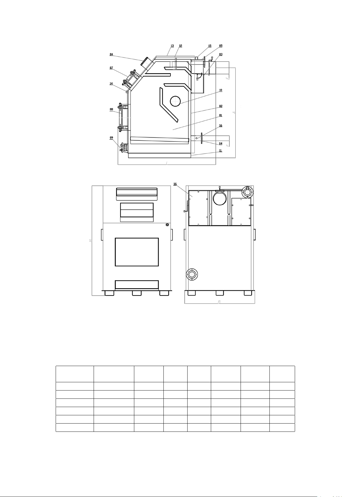
1 Boiler design
Parts of the boiler: 1. Combustion chamber 2. Hot water 3. Flue gases 4. Return 5. Flow 6. Upper
opening for cleaning 7. Upper door for fuel feed 8. Lower door for fuel feed and ash cleaning 9. Primary air
flap 10. Side openings for cleaning 11. Base 12. Insulation 13. Boiler housing 14. Draught regulator mounting
place 15. Air vent connection 16. Drain tap
1.1 Dimensions
Boiler type Weight (kg) B (mm) H
(mm)L(mm)
100 630 935 1500 1540 1330 220 2
120 760 935 1600 1665 1430 220 2
150 805 1035 1670 1675 1500 220 No65
200 1030 1205 1720 1785 1535 220 No80
250 1500 1355 1800 2075 1570 330 No80
300 1700 1600 1800 2075 1570 330 No80
A (mm) E (mm) F (Φ )
1.2 Technical data chart according to EN 303-5
2
Page 4

Nominal power* TKK3 max (KW) 100 120 150 200 250 300
Max power coal* (KW) 100 120 150 200 250 300
Max power wood* (KW) 87 103,5 129 169,5 210 262,5
Power range coal* (KW) 80-110 100-
130
Necessary draught (mbar) 0.29 0.3 0.35 0.41 0.45 0.5
Water content (l) 170 230 290 320 350 430
Output gas temperature at nominal power (◦C) 250 250 250 250 250 250
Temp. regulation range (solid fuel) (◦C) 60-90 60-90 60-90 60-90 60-90 60-90
Minimum temp. return line (solid fuel) (◦C) 60 60 60 60 60 60
Efficiency 76,7% 81,8% 81,6% 81,8% 81,9% 79,2%
Boiler class 3 3 3 3 3 3
Required chimney height** (m) 9-10 10-11 11-12 11-12 12-13 15-17
Required chimney inner diameter** (mm) 250 250 300 350 350 350
* Values given for coal with caloric value 18000 KJ/kg and in the field below for firewood with caloric
value of 15000 KJ/kg. ** Please consult chimney producer manual for detailed information on chimney.
130180
180240
220290
270350
1.3 Maximum Wood Log Size
When using firewood, please note that this is the maximum log length you can put into the boiler.
Boiler type TKK3 max (KW) Max wood log length (mm) Heating chamber depth (mm)
100 800 812
120 900 912
150 900 912
200 1000 1015
250 1200 1215
300 1200 1215
1.4 On Product
• This boiler is aimed for manual feed of solid fuel (brown coal, firewood, brickets or biomass with
declared caloric value greater than 15000 KJ/kg).
• Boiler is constructed by welding steel plates (4-6 mm thickness). Manufacturing process was performed by strict following the guidelines of the corresponding European norms EN 303/5 and ISO
9001. Only certified materials are built in as required by EN 10025, EN 10028-2, EN 10120 and EN
10088-2.
• Efficiency of the boiler is higher than 77% thanks to its three pass construction.
• Upper and lower door are covered by refractory insulation material based on VERMICULITE
mineral - large amount of heat is kept in the boiler as a consequence.
• Boiler has capacious upper door to facilitate manual feeding of the solid fuel.
• Combustion control is done by draught regulator (to be ordered separately and mounted on boiler
before use).
• Maximum working pressure is 4 bar. Water control test is done on 6 bar.
• Boiler is delivered with cleaning kit.
3
Page 5

2 Recommendations for boiler shipment and storage
2.1 Delivery form
The boiler is wrapped with plastic sheet, the whole set is transported on wood pallet.
The boiler must always stand in its vertical position. The rotation of the boiler during the shipment or
installation represents a serious risk and can lead to damaging the boiler. It is forbidden to stack boilers
vertically one onto other.
The boiler can be stored only in closed rooms with no atmospheric influence. The humidity in the storing
room also must not exceed the critical value of 80%, so as not to create any condensate. The temperature
of the storing room must be in the range of +/- 40 ˚C.
2.2 What’s in the box
The following parts are supplied together with the boiler:
• Cleaning kit
• Warranty note
3 Boiler installation
3.1 Boiler placement
The boiler room should have air-conditioning. Equation for the are aof opening for fresh air necessary
for boiler room is given below:
A(cm2) = 6, 02 · P (K W )
where P is nominal boiler power in KW.
The boiler should be mounted in the boiler room permiting access to all its parts as shown below:
3.2 Chimney
Boiler connection to the chimney is shown in the figure:
4
Page 6

Proper dimensioning of the chimney is a very important premise for optimum boiler performance.
The purpose of the chimney is to take out the products of combustion but also to secure necessary air
draught in the boiler. The graph shows how to chose the necessary height for the chimney as a function of chimney opening. Proper chimney insulation is very important and should be at least 50 mm thick.
Depending on the necessary draught of the boiler, the cross section and the height of the chimney
are determined. Please advise technical material given by chimney producer. Minimum chimney height
for TKK3 max 120 wood boiler is 9 m. Estimate for chimney height is given in the technical data
chart. Round chimney made of stainless steel modules is recommended in order to keep the condensation
influence low.
4 Boiler installation
4.1 Fitting the boiler to a closed central heating system
Depending on the position of the boiler in relation to the pipe-work and the radiators – the installation
can be carried out using one of two methods.
4.1.1 Installation method 1
If the boiler is positioned on the same level or higher than the pipe-work and radiators.
Each of the following items of equipment shall be fitted along the flow line:
1. Aeration vessel.
2. Safety valve (spring valve is recommended).
3. Expansion vessel.
4. Boiler valve.
5
Page 7

Aeration vessel to be fitted at highest point of the system at top of boiler outlet. This should include
an overflow system with valve to discharge air from the boiler to prevent overheating.
A float operated valve allows water into a cistern fitted with an overflow pipe. When the system is
filling, the valve remains open. When the system is full the valve closes.
Temperature of hot water within a storage system. Irrespective of the type of fuel used for
heating, the temperature of the water at any point within a hot water storage system should not exceed
100 ˚C and appropriate vent pipes, temperature control devices and other safety devices should be
provided to prevent this occurring.
Safety Pressure Valve (PSV). The safety pressure valve must always be positioned and mounted
close to the boiler. It must be easily identifiable and allow for easy access. The safety pressure valve must
be set to a nominal pressure of 2.5 bar. The valve must open and operate smoothly at 2.5 bar. Diameter
for the aperture at the seat of the valve must be at least 15mm. Connecting pipe- work to the boiler
must be as short as possible. Welds, joints or any possible blockage to this pipe-work must be prevented.
Bends in the pipe-work should be avoided if possible. Unavoidable bends should be at diameter r>3D
(D = radius of curvature) and less than α > 90 ˚C.
Closed expansion vessel. The closed expansion vessel shall be fitted close to the boiler. Connecting
pipe-work should be as short as possible. Fit the expansion vessel in horizontal alignment to the pipe
to ensure equal distribution of pressure. The volume of the expansion vessel is determined by the output/capacity of the boiler. A ratio of 1 kW:1 litre should be used.
The safety pressure valve and the expansion vessel should be fitted in close proximity to each other,
in the following order: expansion vessel closest to the boiler, followed by the safety pressure valve.
It is also recommended to mount a dirt remover on the RETURN line.
In the event of power failure and the boiler fails to operate correctly – any sudden increase of pressure
will be controlled first by the expansion vessel, on any further increase in pressure the safety pressure
valve will open.
6
Page 8

Great care must be taken to ensure air does not enter the boiler.
4.1.2 Installation method 2
To be used in the case of the boiler being positioned and installed at a lower level than the installed
pipe-work and radiators.
As shown on Figure, following elements are connected along the FLOW:
1. Automatic air vent
2. Safety valve
3. Circulation pump (separated with ball valves on each side so that it can be easily replaced if
necessary).
For safe operation info on additional equipment such as expansion vessel and safety valve please refer
to manuals to be delivered with such products.
This air vent valve must be open when first filling the boiler on installation completion.
4.2 Fitting the boiler to an open central heating system.
The connecting scheme of an open central heating system is depicted on the figure.
Open expansion vessel is connected to the hot-water distribution pipes (FLOW and RETURN) as
shown on Figure – with an additional OVERFLOW pipe output plus CIRCULATION pipe (to prevent
freeze during winter months).
Please note that no additional items shall be connected to the open expansion vessel – especially not
valves.
The size of expansion vessel is deducted from the following equation:
V = 0, 07V
V
(l) is the water volume in the entire installation.
water
Open expansion vessel is to be positioned vertically above the highest heating element. Both flow an
return line connecting the open expansion vessel must be insulated (40 mm thickness). if the expansion
vessel is outside the heating area, the vessel itself should be insulated.
7
water
(l)
Page 9

4.3 Filling up the boiler and installation with water
Filling is done using the drain tap valve (to be found on the return line close to boiler). The filling process
is done when no air is coming out. Working pressure depends on the overall height of the system and the
open expansion vessel (1 bar for each 10 m is an estimate).
After the filling process is done, it is obligatory to close the drain tap valve, close the water supply to
the water-filling pipe and detach the water-filling pipe.
Pay attention to quality of water which is used to fill the heating system.
An expert should be entrusted with the mounting of the heating and the initial operation. This must
be a person who will take over the responsibility and guarantee the correct operation of the boiler and
of the complete central heating system. In the case of an incorrectly planned system with manifesting
deficiencies caused by the respective person’s incorrect installation of the system, which can again lead
to an incorrect operation of the boiler, the complete liability for the material damage and potential new
costs arising in relation to it is borne exclusively by the person who was entrusted with the mounting of
the central heating system, and not by the boiler manufacturer, sales representative or seller.
5 Boiler operation
First putting into operation is performed exclusively by a skilled person. Before putting in operation
please make sure that:
• boiler is connected on central heating installation properly
• boiler is connected on electric installation properly (when using pellet or oil burner)
• there is no air in the central heating installation and pressure is within range
• proper working cycle for circulation pump is chosen.
Heating by solid fuel (manual operation) can be performed in two ways:
1. Heating from above – put coal (or wood) over the fireplace pipes (“grid”) (no ash should be present).
The draught regulator is at the maximum position. Using a tiny piece of wood or coal, light a fire on
the top. When the fire begins to burn, draught regulator is set on desired temperature / position.
2. Heating from below – put small amount of solid fuel over the fireplace pipes (“grid”) (no ash should
be present) and set up a fire. The draught regulator is at the maximum position. When the
8
Page 10

fire begins to burn, add larger amount of fuel and set draught regulator on desired temperature /
position.
Make sure that lower boiler doors are closed during boiler use.
In case of an uncontrolled increase of pressure and temperature of the water in the boiler, due to
various reasons (such as power failure causing interruption of the circulation pump operation, circulation
pump defect, uncontrolled entry of air into system) close all air supply to the boiler or eventually take
the fire out if the safety conditions allow that (there are no inflammable materials in the area). In case of
power failure put the draught regulator in the zero position and the flap on the boiler chimney take-up
in the closed position.
It is obligatory to pay special attention that the pressure inside the installation is within range. If
the pressure is below the critical value, stop the boiler operation and refill the system when the boiler is
cold.
The water hardness may not exceed the recommended value. If you heat the boiler using coal, depending on the kind of coal and quality of combustion, boiler is to be cleaned in detail at least every 30
days. Dirtier the boiler, the efficiency of the system is smaller.
It is not allowed to extinguish the fire in the boiler artificially, it is forbidden to sprinkle the water
inside the heating chamber. After the heating season boiler should cleaned from ash and soot and the
chamber should be treated with some protection agent against corrosion.
In case of any mechanical problem (the draught regulator is blocked, or the circulation pump is defect)
stop the boiler operation first – only when the boiler is cold, reparation action can be undertaken.
6 Boiler cleaning and maintenance
It is recommended that the boiler is cleansed from ash once to two times weekly. A detailed cleansing
of the boiler should be done once a month and also when the heating season ends. Regular maintenance
extends the service life of the boiler. Cleaning is to be done through upper and lower door of the boiler
but also using the opening on the back side (chapter 1, position 10).
9
 Loading...