

Page 1
Wood logs boiler with a gasication eect IGNIS 20-40 KW
INSTRUCTIONS MANUAL
for usage and maintenance
Prhovacka bb 22310 Simanovci, Srbija
Tel/Fax. +381 22 480404 +381 63 259422
oce@termomont.rs www.termomont.rs
May 17, 2011
Page 2
Contents
1 Boiler design and properties 2
1.1 Dimenzije . . . . . . . . . . . . . . . . . . . . . . . . . . . . . . . . . . . . . . . . . . . . . 2
1.2 Technical properties according to EN 303-5 . . . . . . . . . . . . . . . . . . . . . . . . . . 2
1.3 On product . . . . . . . . . . . . . . . . . . . . . . . . . . . . . . . . . . . . . . . . . . . . 3
2 How It Works 3
3 Recommendations for boiler shipment and storage 4
3.1 Delivery form . . . . . . . . . . . . . . . . . . . . . . . . . . . . . . . . . . . . . . . . . . . 4
3.2 What's in the box . . . . . . . . . . . . . . . . . . . . . . . . . . . . . . . . . . . . . . . . 4
4 Boiler installation 5
4.1 Boiler placement . . . . . . . . . . . . . . . . . . . . . . . . . . . . . . . . . . . . . . . . . 5
4.2 Chimney . . . . . . . . . . . . . . . . . . . . . . . . . . . . . . . . . . . . . . . . . . . . . . 5
5 Connecting the boiler with a central heating system 7
5.1 Closed system . . . . . . . . . . . . . . . . . . . . . . . . . . . . . . . . . . . . . . . . . . . 7
5.2 Closed system combined heating with solar panels . . . . . . . . . . . . . . . . . . . . . . 8
5.3 Closed system combined heating with solar panels . . . . . . . . . . . . . . . . . . . . . . 9
5.4 Open system . . . . . . . . . . . . . . . . . . . . . . . . . . . . . . . . . . . . . . . . . . . 10
6 Boiler In Use 11
6.1 Circulation Pump Thermostat . . . . . . . . . . . . . . . . . . . . . . . . . . . . . . . . . . 11
6.2 Maintenance and cleaning . . . . . . . . . . . . . . . . . . . . . . . . . . . . . . . . . . . . 11
7 Safety features 11
7.1 Thermal safety in case of overheat (closed systems) . . . . . . . . . . . . . . . . . . . . . . 11
A Deklaracija o Konformnosti 13
1
Page 3
1 Boiler design and properties
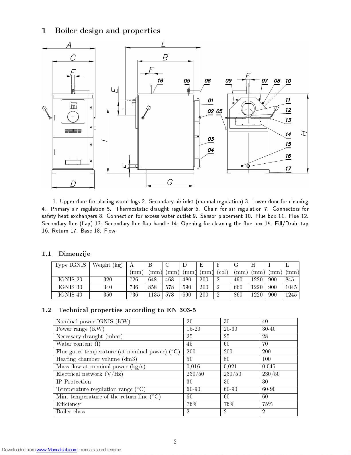
1. Upper door for placing wood-logs 2. Secondary air inlet (manual regulation) 3. Lower door for cleaning
4. Primary air regulation 5. Thermostatic draught regulator 6. Chain for air regulation 7. Connectors for
safety heat exchangers 8. Connection for excess water outlet 9. Sensor placement 10. Flue box 11. Flue 12.
Secondary ue (ap) 13. Secondary ue ap handle 14. Opening for cleaning the ue box 15. Fill/Drain tap
16. Return 17. Base 18. Flow
1.1 Dimenzije
Type IGNIS Weight (kg) A
(mm)B(mm)C(mm)D(mm)E(mm)F(col)G(mm)H(mm)I(mm)L(mm)
IGNIS 20 320 726 648 468 480 200 2 490 1220 900 845
IGNIS 30 340 736 858 578 590 200 2 660 1220 900 1045
IGNIS 40 350 736 1135 578 590 200 2 860 1220 900 1245
1.2 Technical properties according to EN 303-5
Nominal power IGNIS (KW) 20 30 40
Power range (KW) 15-20 20-30 30-40
Necessary draught (mbar) 25 25 28
Water content (l) 45 60 70
Flue gases temperature (at nominal power) (◦C) 200 200 200
Heating chamber volume (dm3) 50 80 100
Mass ow at nominal power (kg/s) 0,016 0,021 0,045
Electrical network (V/Hz) 230/50 230/50 230/50
IP Protection 30 30 30
Temperature regulation range (◦C) 60-90 60-90 60-90
Min. temperature of the return line (◦C) 60 60 60
Eciency 76% 76% 75%
Boiler class 2 2 2
2
Page 4
1.3 On product
•
Boiler primarily uses dry wood as fuel with caloric value > 15 MJ/kg, max. moisture content 15%;
•
Boiler is produced following the guidelines of the European norm EN 303/5;
•
According to norm demands inner walls of the boiler are 5 mm thick;
•
Combustion takes place inside the heating chamber specially designed to put large amount of wood-
logs
•
Single combustion load can hold up to 6 hours
•
Boiler comes with removable ash-tray, cleaning kit and thermometer;
•
The upper zone of the boiler has a special round shape made of reproof ceramics with turbulators
for optimum eciency;
•
Water test is done at 6 bar pressure.
2 How It Works
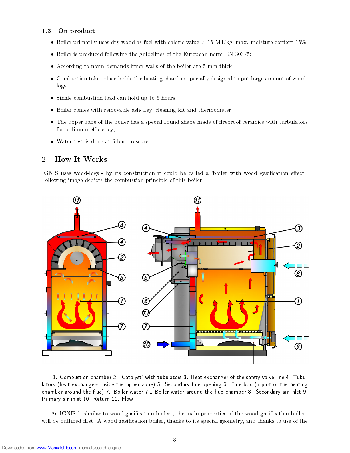
IGNIS uses wood-logs - by its construction it could be called a 'boiler with wood gasication eect'.
Following image depicts the combustion principle of this boiler.
1. Combustion chamber 2. 'Catalyst' with tubulators 3. Heat exchanger of the safety valve line 4. Tubu-
lators (heat exchangers inside the upper zone) 5. Secondary ue opening 6. Flue box (a part of the heating
chamber around the ue) 7. Boiler water 7.1 Boiler water around the ue chamber 8. Secondary air inlet 9.
Primary air inlet 10. Return 11. Flow
As IGNIS is similar to wood gasication boilers, the main properties of the wood gasication boilers
will be outlined rst. A wood gasication boiler, thanks to its special geometry, and thanks to use of the
3
Page 5
fan, brings the woodlogs in the state of 'gasication' - the process where light weighted hydrocarbons. The
ame has a specyphic blue colour and the eciency of such solid fuel boiler is 10-15% greater than that of
the conventional ones. Another interesting property of wood gasication boilers is that the woodlogs are
placed in the upper chamber and the ame is inverse - going upside down contrary to conventional boilers.
Wood gasication combustion requires a constant and stationary boiler operation. It is thus necessary
to have an additional heat tank to accept the excess heat made by boiler. It is also necessary to perfectly
adjust temperatures between the heat tank, ow and return line of the boiler to prevent condensation. All
in one, wood gasication allows maximum comfort with wood-logs as a fuel, but with certain investment
to be made into additional equipment.
The IGNIS boiler lls the room between the less pricey conventional boilers, which demand rell
of wood more often and maximum comfort yet more pricey wood gasication boilers (with heat tank).
Because of its technical construction IGNIS allows the wood gasication eect (in amoutn much less
than 'real' wood gasication boilers) but only using the natural draught of the boiler, without a fan and
without a necessary heat tank. What is still necessary is the protection against condensation (mixed
valve, by pass of the boiler). IGNIS does not have an inverse ame.
As it does not posses the automatic regulation via fan, optimum combustion is achieved by setting the
primary and secondary air. Primary air is controlled by the draught regulator (to be ordered separately)
and the secondary air is to be set manually.
In which way the wood gasication eect is achieved? Wood gasication process takes place in the
upper zone of the boiler - within the so-called 'reproof catalyst'. This is a special cylindric part of the
heating chamber. On its upper side there are special heat exchangers (tubulators). Below the catalyst
with presence of secondary air, at very high temperatures, solid particles are accelerated to certain level
until they combust completely. Short-chain hydrocarbons are released. Flue gases are passing through
turbulators - in contact with increased surface of the tubulators ue gases are additionally cooled down -
exit ue gas temperature is thus lower compared with conventional boilers. The eciency is higher. The
concentration of dust, particles and COX/NOX is lower.
IGNIS has a secondary ap inside the chamber. The role of this is to shorten the passage of ue
gases and increase the draught in the boiler when necessary (during ignition for instance). when th ere
is stable this secondary ap should be closed. IGNIS also has a so-called 'ue-box'. Water content of the
boiler is maximized occupying a part of the ue chamber.
3 Recommendations for boiler shipment and storage
3.1 Delivery form
The boiler comes in three parts, boiler chamber, pellet storage and the boiler housing packed separately.
Chamber is wrapped with plastic sheet, and upper door containing reproof glass should have a small
styrofoam protection sheet. The whole set is transported on wood pallet.
The boiler must always stand in its vertical position. The rotation of the boiler during the shipment or
installation represents a serious risk and can lead to damaging the boiler. It is forbidden to stack boilers
vertically one onto other.
The boiler can be stored only in closed rooms with no atmospheric inuence. The humidity in the storing
room also must not exceed the critical value of 80%, so as not to create any condensate. The temperature
of the storing room must be in the range of +/- 40 C.
3.2 What's in the box
The following parts are supplied together with the boiler:
•
Cleaning kit
4
Page 6
•
Cleaning brush
•
Warranty paper
4 Boiler installation
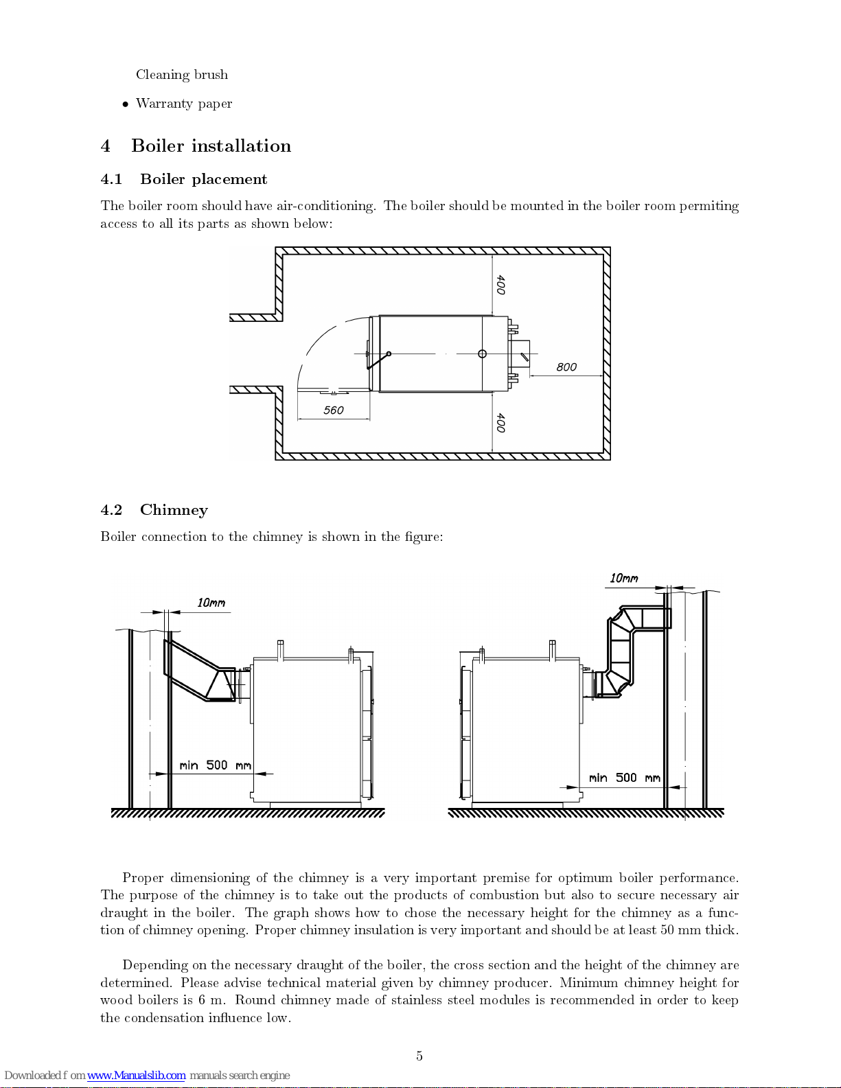
4.1 Boiler placement
The boiler room should have air-conditioning. The boiler should be mounted in the boiler room permiting
access to all its parts as shown below:
4.2 Chimney
Boiler connection to the chimney is shown in the gure:
Proper dimensioning of the chimney is a very important premise for optimum boiler performance.
The purpose of the chimney is to take out the products of combustion but also to secure necessary air
draught in the boiler. The graph shows how to chose the necessary height for the chimney as a func-
tion of chimney opening. Proper chimney insulation is very important and should be at least 50 mm thick.
Depending on the necessary draught of the boiler, the cross section and the height of the chimney are
determined. Please advise technical material given by chimney producer. Minimum chimney height for
wood boilers is 6 m. Round chimney made of stainless steel modules is recommended in order to keep
the condensation inuence low.
5
Page 7

6
Page 8

5 Connecting the boiler with a central heating system
5.1 Closed system
The following schemes show how to connect the boiler to the central heating installation with or without
a heat accumulator tank:
System parts: 1. Boiler 2. Heat accumulator 3. Heat exchanger 4. Non-return valve 5. Mixing valve
6. Pump of the radiator heating 7. Automatic regulation for the radiator heating 8. Expansion vessel 9.
Exchanger pump 10.Valve 11.Thermo-manometer 12. Expansion vessel 13. Four-arm mixing valve 14.
7
Page 9
It is not necessary to install the heat accumulator. However, it is recommended.For 1 KW power of
the boiler, a capacity of the heat accumulator of 25-50 l is recommended. One must also bear in mind
that the power of the boiler must be enough in order to both warm up the water in the accumulator,
as well as to provide direct feed to the installation in very cold periods the chosen power of the boiler
should be 1.5 higher than the power of an oil-gas boiler for the given squaring.
It is recommended that the closed central heating system is supplied with an expansion tank, the
capacity of which must amount to at least one tenth of the total capacity of the system (including the
water volume in the boiler). The system must also have an automatic aeration valve with the help of
which air will be eliminated from the system. The use of a safety valve is obligatory (with a 2-3 bar
threshold, depending on the power of the boiler) and it must be mounted near the boiler.
It is also necessary that the system has a thermometer and manometer in order to read the temperature
and pressure in the system. In case of using conventional solid fuel, the temperature of the return line
should not fall below 60C, so as to avoid leaking, i.e. condensation in the boiler, which can further lead
to corrosion. The temperature of the starting line should not fall below 70C. It is recommended to use
a four-arm mixing valve on the return line of the boiler or a regulation group such as LADDOMAT 21.
It is also recommended to mount a lth catcher on the return line.
Qualied installer should be entrusted with the mounting of the heating and the initial operation.
This must be a person who will take over the responsibility and guarantee the correct operation of the
boiler and of the complete central heating system. In the case of an incorrectly planned system with
manifesting deciencies caused by the respective person's incorrect installation of the system, which can
again lead to an incorrect operation of the boiler, the complete liability for the material damage and
potential new costs arising in relation to it is borne exclusively by the person who was entrusted with
the mounting of the central heating system, and not by the boiler manufacturer, sales representative or
seller.
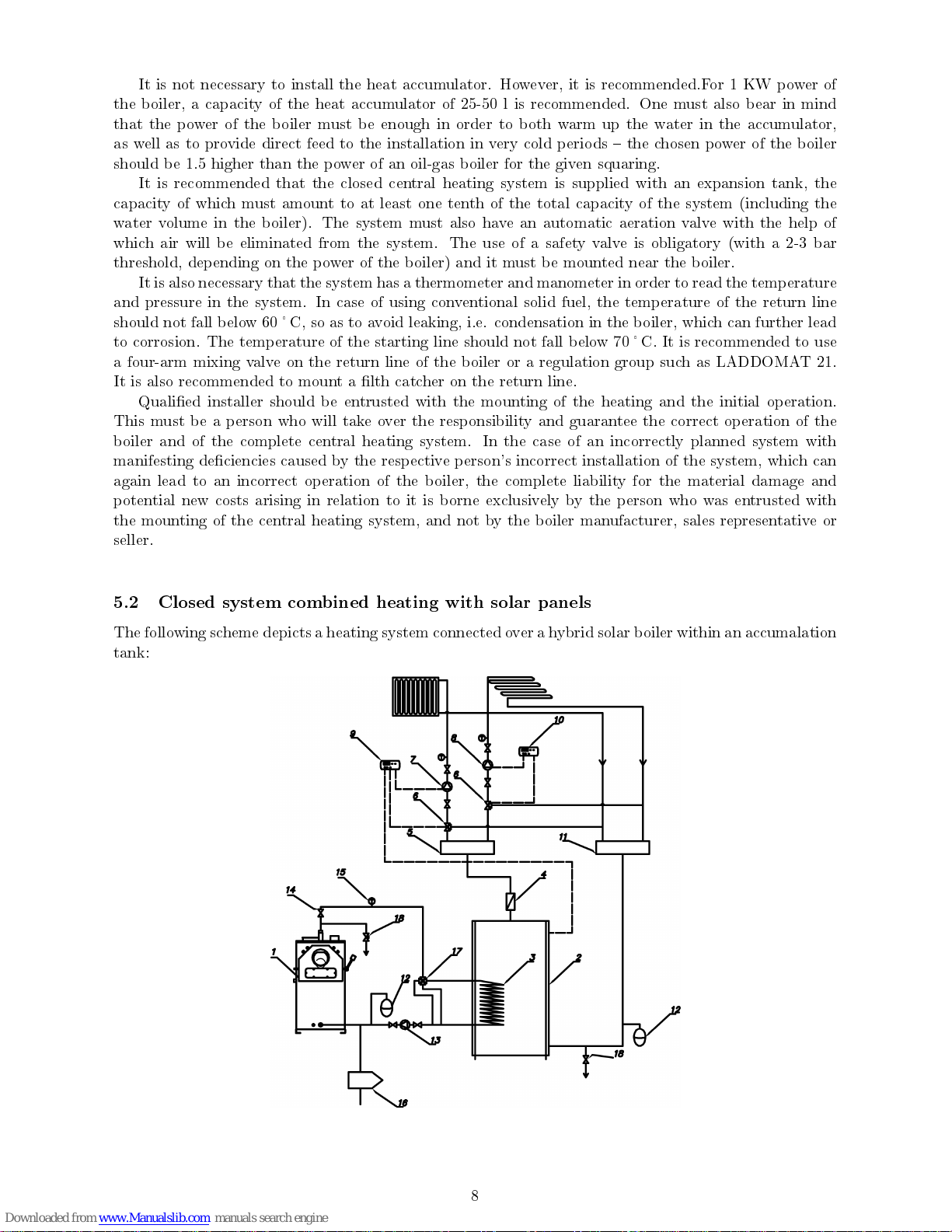
5.2 Closed system combined heating with solar panels
The following scheme depicts a heating system connected over a hybrid solar boiler within an accumalation
tank:
8
Page 10

System parts: 1. Boiler 2. Heat accumulator 3. Heat exchanger 4. Non-return valve 5. Distributor 6.
Mixing valve 7. Pump of the radiator heating 8. Pump of the oor heating 9. Regulator of the automatic
regulation for the radiator heating 10. Regulator of the automatic regulation for the oor heating 11. Receiver
12. Expansion tank 13. Exchanger pump 14.Valve 15.Thermo-manometer 16. Filth catcher 17. Four-arm
mixing valve 18. Safety valve
5.3 Closed system combined heating with solar panels
Termomont in its oer of solar boilers also has a 'hybrid' version of a heat accumulation tank and
stainless steel solar boiler in one: ATS combined tank. When boiler heats up the 'technical' water inside
the boiler - as do the solar panels through the spirale. The drinking water is inside the inner vessel which
9
Page 11
is heaten indirectly by the technical water.
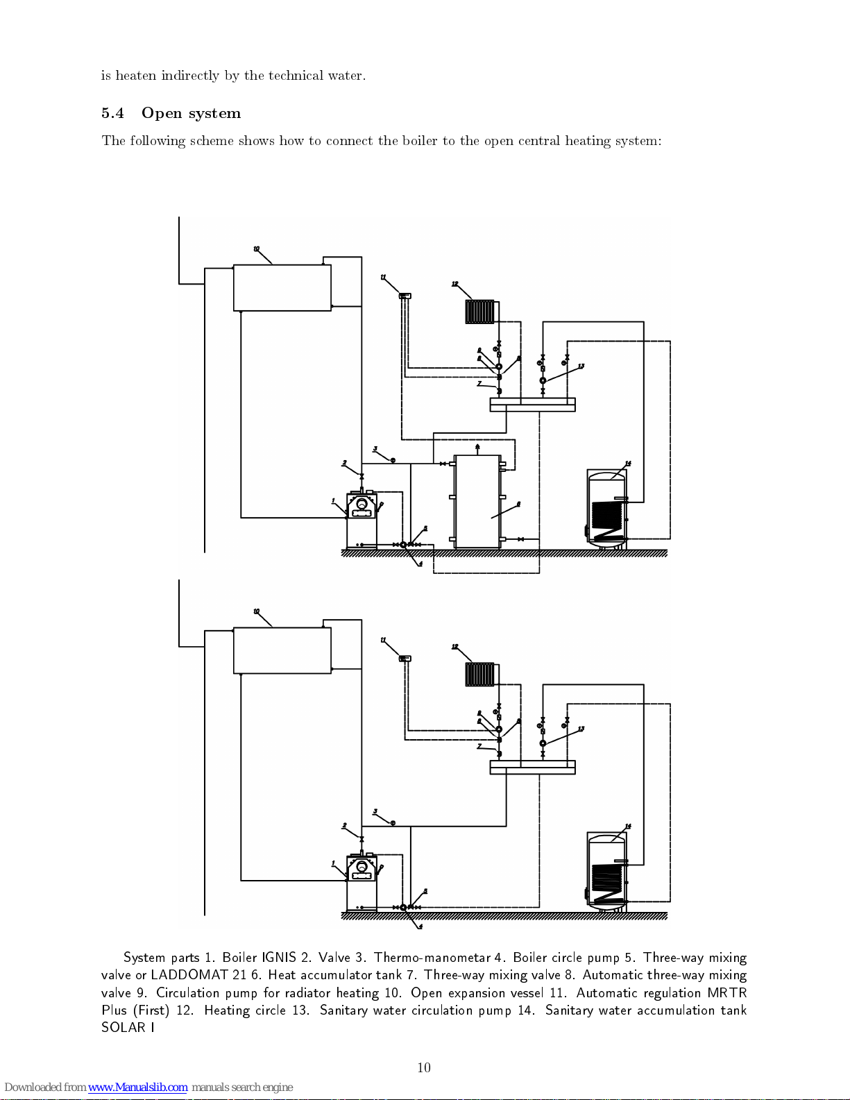
5.4 Open system
The following scheme shows how to connect the boiler to the open central heating system:
System parts 1. Boiler IGNIS 2. Valve 3. Thermo-manometar 4. Boiler circle pump 5. Three-way mixing
valve or LADDOMAT 21 6. Heat accumulator tank 7. Three-way mixing valve 8. Automatic three-way mixing
valve 9. Circulation pump for radiator heating 10. Open expansion vessel 11. Automatic regulation MRTR
Plus (First) 12. Heating circle 13. Sanitary water circulation pump 14. Sanitary water accumulation tank
SOLAR I
10
Page 12
6 Boiler In Use
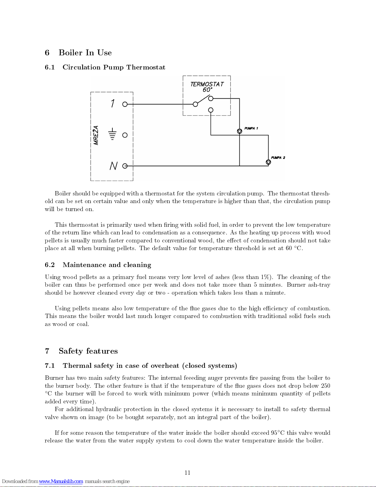
6.1 Circulation Pump Thermostat
Boiler should be equipped with a thermostat for the system circulation pump. The thermostat thresh-
old can be set on certain value and only when the temperature is higher than that, the circulation pump
will be turned on.
This thermostat is primarily used when ring with solid fuel, in order to prevent the low temperature
of the return line which can lead to condensation as a consequence. As the heating up process with wood
pellets is usually much faster compared to conventional wood, the eect of condensation should not take
place at all when burning pellets. The default value for temperature threshold is set at 60◦C.
6.2 Maintenance and cleaning
Using wood pellets as a primary fuel means very low level of ashes (less than 1%). The cleaning of the
boiler can thus be performed once per week and does not take more than 5 minutes. Burner ash-tray
should be however cleaned every day or two - operation which takes less than a minute.
Using pellets means also low temperature of the ue gases due to the high eciency of combustion.
This means the boiler would last much longer compared to combustion with traditional solid fuels such
as wood or coal.
7 Safety features
7.1 Thermal safety in case of overheat (closed systems)
Burner has two main safety features: The internal feeeding auger prevents re passing from the boiler to
the burner body. The other feature is that if the temperature of the ue gases does not drop below 250
◦
C the burner will be forced to work with minimum power (which means minimum quantity of pellets
added every time).
For additional hydraulic protection in the closed systems it is necessary to install to safety thermal
valve shown on image (to be bought separately, not an integral part of the boiler).
If for some reason the temperature of the water inside the boiler should exceed 95◦C this valve would
release the water from the water supply system to cool down the water temperature inside the boiler.
11
Page 13

Connection scheme for the thermal safety valve: 1. Cold water entering from the water supply system 2.
Cold water entry into boiler 3. Hot water going outside the boiler 4. hot water ending in the sewage water
system 5. Thermo-valve sensor
To connect the safety valve:
•
Connect the sensor of the valve (outter thread 1/2") at depicted place on the boiler, position 5
(inner thread 1/2")
•
Connect the cold water entry (on valve's input is marked with C) than connect the exit line (valve
marked with:→) with the corresponding exit line on the boiler (position 21)
•
Connect position 21 (on the boiler) with the input line on the valve (valve is marked with:←)
•
Connect the valve (marked with S) to the sewage system.
12
Page 14

A Deklaracija o Konformnosti
We, Termomont d.o.o. with legal seat on the address Prhova£ka street bb, 22310 imanovci, Republic
of Serbia, under sole responsibility declare that:
Kotlovi na £vrsto gorivo tipa IGNIS 20, IGNIS 30, IGNIS 40
produced 2010. and 2011. as by its construction, design and performances are in accordance with the
following norms and directives prescripted by the European Union:
•
97/23 EEC Pressure device directive
•
EN 303/5 Norm for solid fuel boilers"
imanovci, May 17, 2011
Signature of the responsible person
. .. .. . . . . . .. . .. . .. . .. . .. . .. . .. . .. . ..
13
 Loading...