

H E A T I N G S Y S T E M S
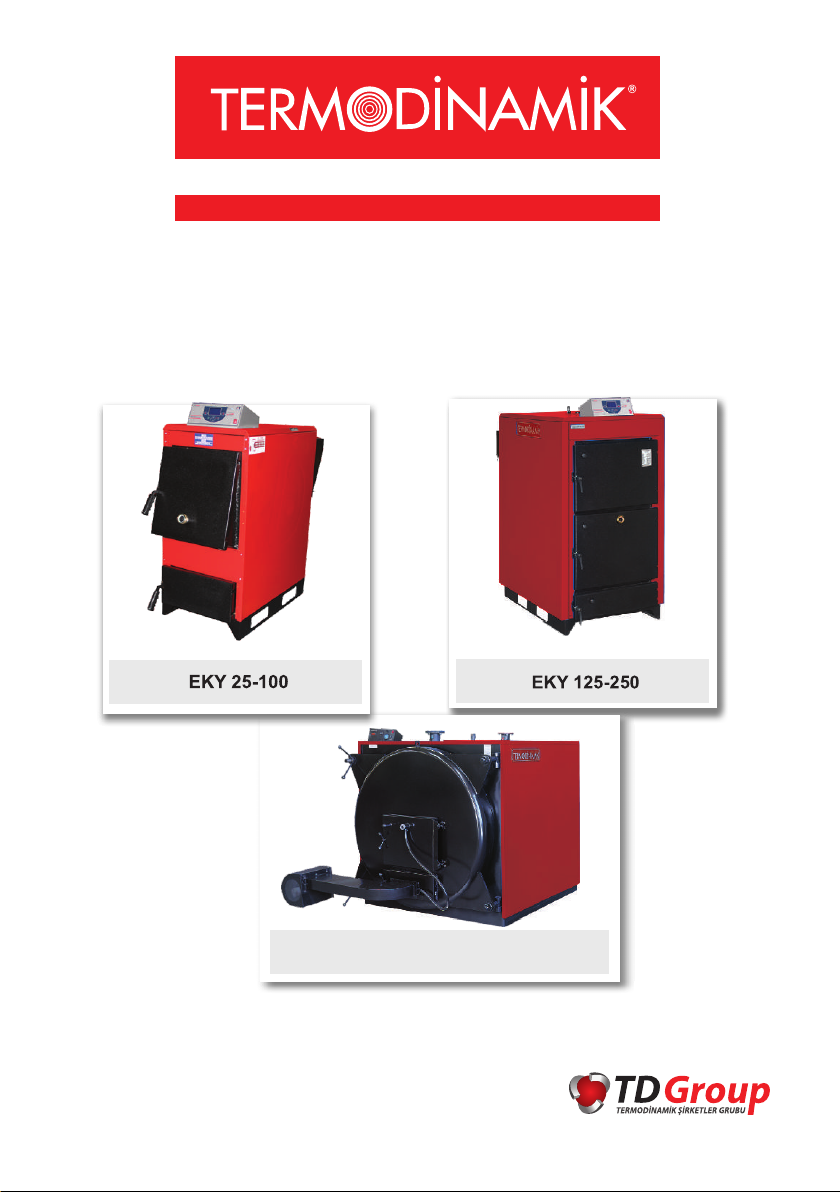
EKY SERIES SOLID FUEL HOT WATER BOILER
WITH MANUAL LOADING
INSTALLATION AND USAGE MANUAL
EKY 125-1000
Digital and mechanical control panel...

H E A T I N G S Y S T E M S
FOREWORD
Dear Customer;
First of all, thank you for choosing our product. We hope you will get
complete satisfaction from DEK Series Electric Combi Boiler.
We would like you to use your device with maximum efficiency, therefore
please read this instruction book carefully before you start using the
product and save it to refer to in the future.
This manual will help you to operate your device safely and efficiently. For
this reason you should pay attention to these:
Please read this instruction book carefully before you install and operate
the product.
Follow the instructions and the rules on safe usage.
The instruction book may apply to other models as well; the differences
between the models are clearly described inside.

H E A T I N G S Y S T E M S
CONTENTS
Foreword
EKY 17-100 Technical Specifications..................................................................1
EKY 125-250 Technical Specifications................................................................3
EKY 125-500 (3 bar) Technical Specifications.....................................................5
EKY 125-1000 (5 bar) Technical Specifications...................................................7
Appliance Information......................................................................................9
Expansion Tank Volumes Suitable for Capacities.............................................11
EKY 17-100, EKY 125-250 Installation Chart................................................12
EKY 125-1000 Installation Chart......................................................................14
EKY 125-1000 Expansion Connection Chart.....................................................15
Common Chimney...........................................................................................16
EKY Digital Control Panel.................................................................................17
Error Codes and Solutions...............................................................................20
EKY Digital Panel Electrical Connection Chart.................................................22
EKY Mechanical Panel Electrical Connection Chart(125-250)......................24
EKY Mechanical Panel Electrical Connections Chart (250-1000)......................25
Use of the Boiler..............................................................................................26
Malfunctions and Troubleshooting.................................................................31
H E A T I N G S Y S T E M S
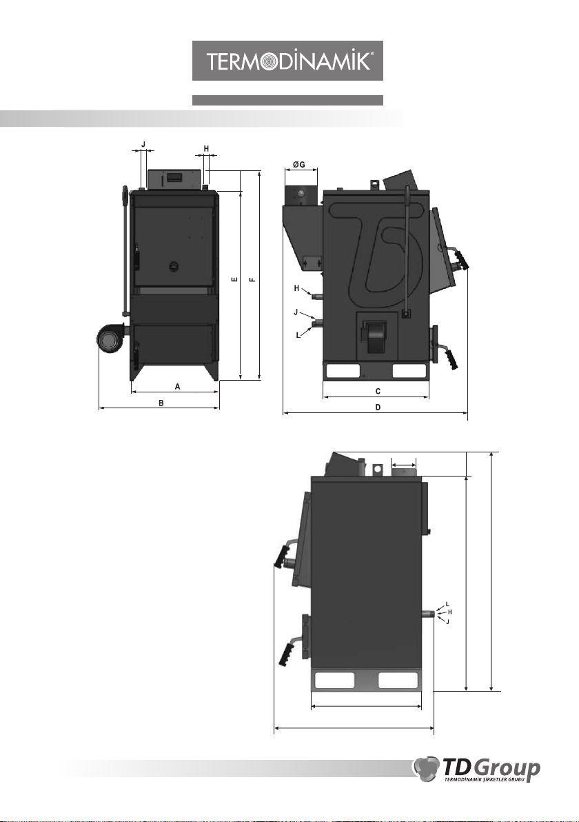
EKY 17-100 TECHNICAL SPECIFICATIONS
G
EKY 17 SIDE VIEW
1
F
E
C
D
H E A T I N G S Y S T E M S
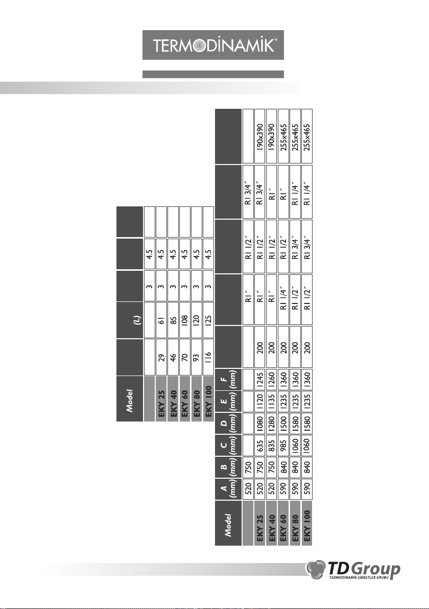
EKY 17-100 TECHNICAL SPECIFICATIONS
kg
255
300
420
Weight
450
Fuel Loading
Lid Dimensions
J (Safety
470
(mm)
Input-Output)
Test
(bar)
Pressure
(bar)
Pressure
Operating
Water
Volume
Kw
(Coal)
Capacity
49
20 183
EKY 17
L (Boiler
Filling-Discharge)
H (Boiler
Input-Output)
(mm)
G Flue
Diameter
560 190x390820 1100 1225 130
EKY 17
We are reserved the right to make changes in dimensions and appearance.
2
H E A T I N G S Y S T E M S
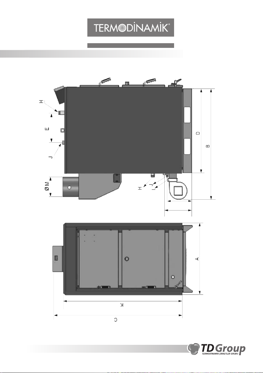
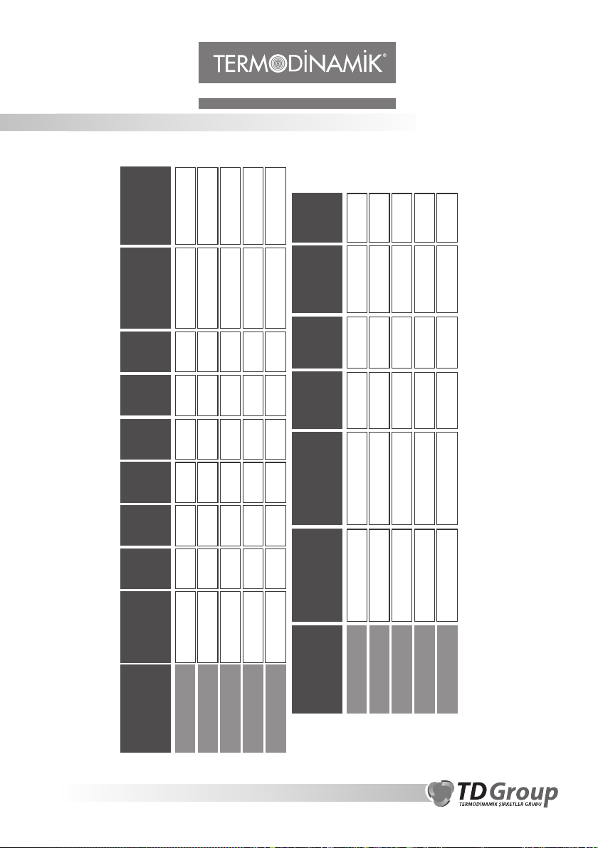
EKY 125 - 250 TECHNICAL SPECIFICATIONS
338 mm
365 mm
3
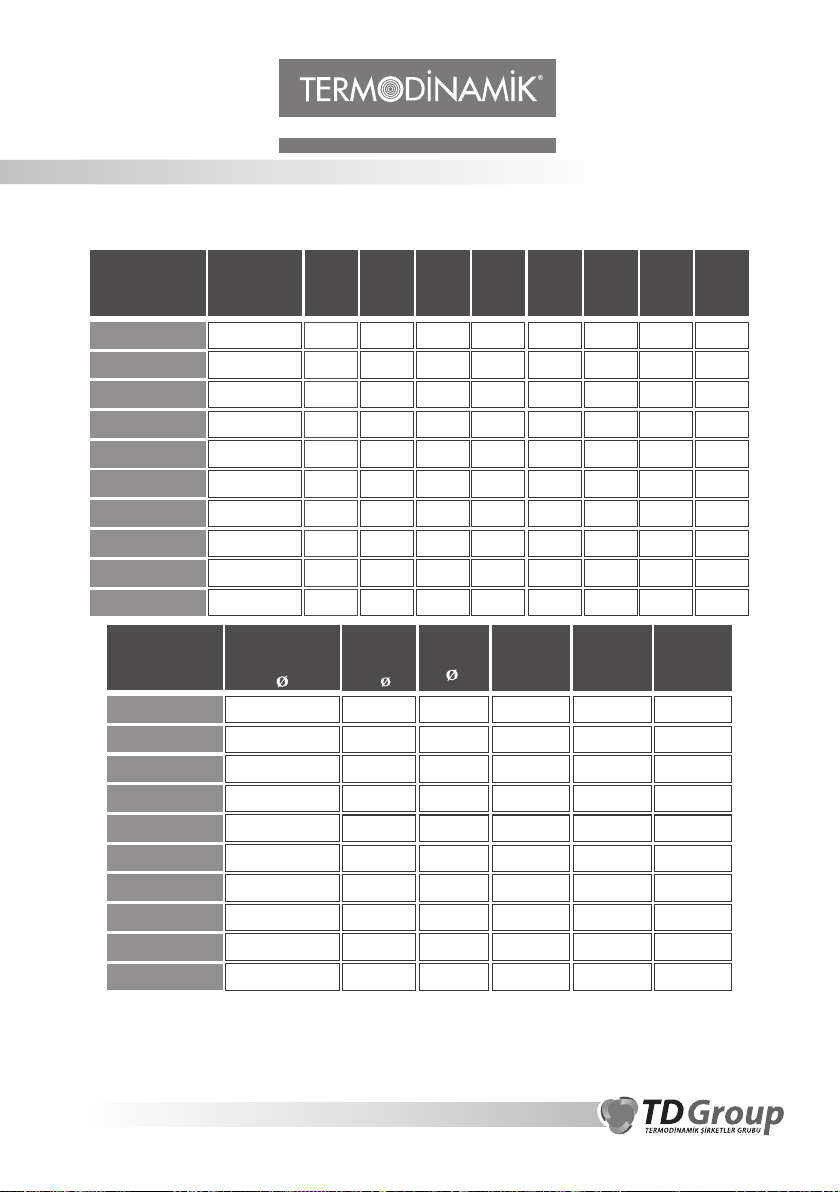
H E A T I N G S Y S T E M S
EKY 125 - 250 TECHNICAL SPECIFICATIONS
250
250
250
250
Flue
ØM(mm)
Diameter
250
(kg)
Weight
930
950
1000
1050
1290
Filling
L (Boiler
Discharge)
K
(mm)
E
(mm)
D
(mm)
C
(mm)
B
(mm)
A
(mm)
Kw
(Coal)
Capacity
Model
R 3/4?
R 3/4?
1520
1520
370
520
1220
1060
1650
1650
1680
1520
790
790
145
174
EKY 125
EKY 150
R 3/4?
R 3/4?
1605
1605
520
680
1380
1220
1735
1735
1680
1840
790
790
203
232
EKY 175
EKY 200
Water
R 3/4?
1630
700
Operating
1570
1760
1980
942
291
EKY 250
(L)
Volume
Test
(bar)
Pressure
(bar)
Pressure
J (Safety
Input-Output)
H (Boiler
Input-Output)
Model
246
236
4.5
4.5
3
3
R 1 1/4?
R 1 1/4?
R1 1/2?
R1 1/2?
EKY 150
EKY 125
256
290
4.5
4.5
3
3
R 1 1/4?
R 1 1/4?
R 2?
R 2?
EKY 175
EKY 200
518
4.5
3
R 1 1/4?
R 2 1/2?
EKY 250
We are reserved the right to make changes in dimensions and appearance.
4

H E A T I N G S Y S T E M S
EKY 125 - 500 (3 BAR) TECHNICAL SPECIFICATIONS
5
H E A T I N G S Y S T E M S
EKY 125 - 500 (3 BAR) TECHNICAL SPECIFICATIONS CHART
Model
EKY 125
EKY 150
EKY 175
EKY 200
EKY 250
EKY 300
EKY 350
EKY 400
EKY 450
EKY 500
(Coal)
Kw
145
174
203
232
290
349
407
465
523
581
CH
Capacity
Model
EKY 125
EKY 150
EKY 175
EKY 200
Input-Output
2 1/2?
2 1/2?
2 1/2?
2 1/2?
EKY 250
EKY 300
EKY 350
EKY 400
EKY 450
EKY 500
We are reserved the right to make changes in dimensions and appearance.
A
(mm)B(mm)C(mm)D(mm)
1340 1350
1340 1350
1340 1350
1340 1350
1640 1550
1640 1550
1840 1810
1840 1810
1840 1810
1840 1810
3?
3?
3?
4?
4?
4?
Expansion
1 1/2?
1 1/2?
1 1/2?
1 1/2?
1 1/2?
1 1/2?
1 1/2?
Boiler
Tank
Output
2?
2?
2?
1065
1195
1315
1495
1400
1690
1706
1826
1996
2272
Boiler
Discharge
3/4?
3/4?
3/4?
3/4?
3/4?
3/4?
3/4?
3/4?
3/4?
3/4?
E
(mm)F (mm)
2240 1010
2370 1010
756 378 350
886 443 350
2490 10101006
2670 10101186
2585 10811088
2875 10811378
2891 12221394
3011 12221514
3181 12221684
3457 12221960
Operating
Pressure
(bar)
3
3
3
3
3
3
3
3
3
3
G
(mm)
(mm)
503 350
593 350
544 400
689 400
697 500
757 500
842 500
980 500
Test
Pressure
(bar)
4.5
4.5
4.5
4.5
4.5
4.5
4.5
4.5
4.5
4.5
Weight
(kg)
1220
1420
1530
1660
2120
2470
3150
3430
3950
4220
H
6
H E A T I N G S Y S T E M S
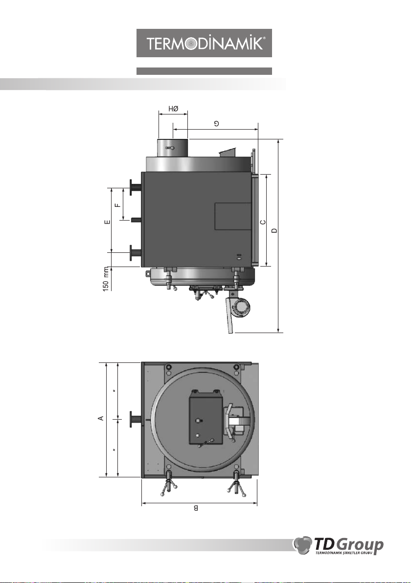
EKY 125 - 1000 (5 BAR) TECHNICAL SPECIFICATIONS CHART
7
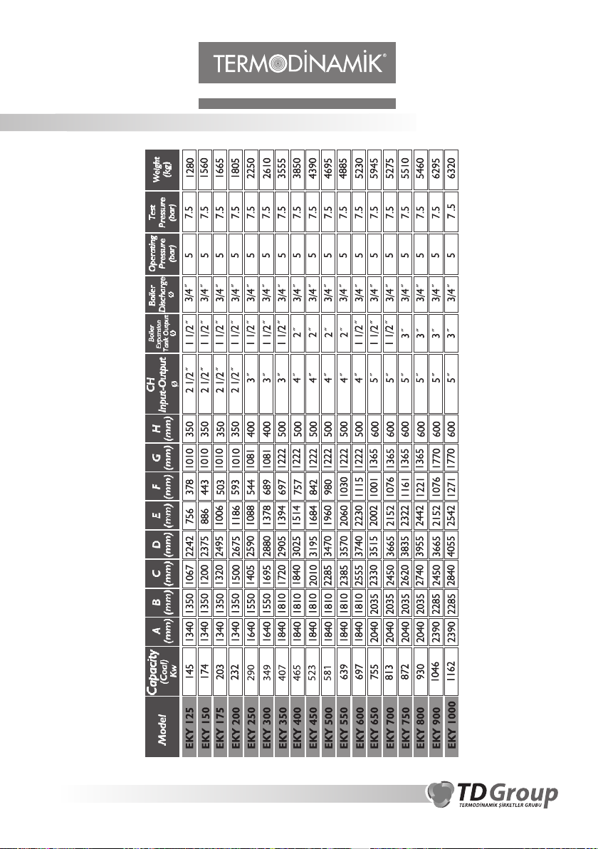
H E A T I N G S Y S T E M S
EKY 125 - 1000 (5 BAR) TECHNICAL SPECIFICATIONS CHART
We are reserved the right to make changes in dimensions and appearance.
8

H E A T I N G S Y S T E M S
APPLIANCE INFORMATION
EKY series boilers are designed to burn different types of fuels such as wood, walnut coal, quince
coal and low-calorie brown coal in ranging capacities. As it is known, the shaft gasses which
occur as a result of burning wood and coal, and condensation of water vapors shall take place.
Make sure not to operate the boiler below 45°C. In case of operation below 45°C, the temperature
of the shaft will be low and this will cause the shaft draft to be insufficient and result in
condensation. Therefore, the life span of the boiler shall be shorter due to corrosion in short time.
The circulation pump in EKY Model boilers stops operating when the boiler water temperature
decreases below 32°C. This is designed to prevent the substantial decrease in the boiler output
water temperature and acid drop (sulfuric acid) resulting from condensation by means of cooling
the firebox.
The fan allowing for burning air stops operating when the boiler water temperature falls under
28°C and the “fuel out” light on the panel indicator is on. This is designed to prevent the fan from
cooling more the shaft gasses in case the boiler fuel decreases. When the shaft gas cools down,
condensation occurs in the shaft. Such condensed water contains acid.
ASSEMBLY INSTRUCTIONS
The boiler should be leveled and installed at least at a distance of 20 cm from ground in boiler
rooms on a durable surface.
The boiler room should be regularly ventilated according to regulations and rule.
When assembling EKY series boilers, it is required to use open expansion tank. The expansion
tank should be located at the top of the installation and the safety pipes should be connected to the
inputs and outputs of the boiler in the shortest route possible. There should never be any flow
control units (valve, check valve, etc.) over the safety pipes. Make sure that the open expansion
tank is always full. The expansion tank volumes suitable for each boiler are given in the table (at
the page 11).
The pump should be installed in such way to avoid boiler and expansion tank flow and return
pipes should not create an air pocket. On points where there is possibility for air to be
accumulated, air tubes or vent systems shall be provided to purge the air.
CORRECT WRONG CORRECT
WRONG
9

H E A T I N G S Y S T E M S
In order to provide for the safety of the boiler and the assembly in case of power outages,
the installation should have a by-pass line.
Make sure to use a suitable check valve for all solid-fuel boilers and the pressure of the
check valve should be equal to the maximum operating pressure of the boiler. On boilers
operating with 3 bar working pressure 3-bar safety valves should be used. (For cylindrical
boilers (25-100) and prismatic (125 and 250) boilers operating with 3-bar).
In regions prone to risk of freezing, expansion tank and insulation should be used.
The diameter of the shaft should not be smaller than the output diameter of the boiler shaft
and the instructions on the shaft assembly specified in this manual should be followed.
During the installation of the appliance, make sure to leave some space around the
appliance depending on the properties of the appliance enough for the technical service to
handle the appliance.
Make sure the location where the appliance and the waste gas disposal line are situated is
not a living space.
In order to minimize the heat loss, the installation pipes should be heat-insulated.
When selecting mono-phase pump, connect the power cable with an open end sticking
out of the panel on the boiler into the electric terminal of the pump. If 3-phase pump is being
used, get a separate panel for the pump.
Connectors and valves should be placed on inlet and outlet lines.
Expansion tank flow and return pipes should be installed with continuous upward
inclination from the boiler to the tank without any downward bending.
WRONG
CORRECT
WRONG
The boiler should be connected to the chimney of
the building without narrowing the diameter at the
flue outlet and through pipes having minimum the
same or larger diameter at the flue outlet and
through pipes having minimum the same or larger
diameter as the boiler flue outlet.
For installation of the boiler warning points indicated in the user manual must be
taken into consideration. The supplier will not take any responsibility for wrong
installation of the boiler and chimney.
10

H E A T I N G S Y S T E M S
EXPANSION TANK VOLUMES SUITABLE FOR BOILER CAPACITIES
Boiler Capacity
(Kcal/h)
25.000
40.000
60.000
80.000
100.000
120.000
150.000
175.000
200.000
250.000
300.000
350.000
400.000
450.000
500.000
550.000
600.000
650.000
700.000
750.000
800.000
900.000
1.000.000
If Cast Sectional
Heating Radiators
are used
45 L17.000 26 L
65 L
100 L
150 L
200 L
250 L
292 L
333 L
417 L
500 L
625 L
750 L
857 L
1000 L
1125 L
1250 L
1375 L
1500 L
1625 L
1750 L
1875 L
2000 L
2250 L
2500 L
If Panel Radiators
are used
42 L
67 L
100 L
135 L
167 L
200 L
250 L
292 L
333 L
417 L
500 L
583 L
667 L
750 L
833 L
917 L
1000 L
1083 L
1167 L
1250 L
1333 L
1500 L
1667 L
The values given above are intended for nominal conditions. The contractor company shall
perform the precise evaluation and calculations depending on the location and operation
conditions of the boiler.
11

H E A T I N G S Y S T E M S
EKY 25-100, EKY 125-250 INSTALLATION CHART
PUMP ON OUTLET
A. Input to the Radiators
B. Output from the Radiators
C. Open Expansion Tank
D. Input to the Expansion Tank
E. Output from the Expansion Tank
F. Messenger Line
G. Radiators
H. Air-Purge Valve
I. By-Pass Line Valve
J. Main Valve Pump
K. Main Valve
L. Filling Valve
G G
H
C
K
J
J
A
I
D
12
B
E
L
F

H E A T I N G S Y S T E M S
EKY 25-100, EKY 125-250 INSTALLATION CHART
PUMP ON INLET
A. Input to the Radiators
B. Output from the Radiators
C. Open Expansion Tank
D. Input to the Expansion Tank
E. Output from the Expansion Tank
F. Messenger Line
G. Radiators
H. Air-Purge Valve
I. By-Pass Line Valve
J. Main Valve Pump
K. Main Valve
L. Filling Valve
G
H
C
G
A
D
13
B
K
J J
I
L
E
F

H E A T I N G S Y S T E M S
EKY 125-1000 INSTALLATION CHART
(EXCEPT FOR PRISMATIC 125-250 SERIES)
Air Vent
O
A
TO RADIATORS
B
FROM RADIATORS
C
OPEN EXPANSION TANK
EXPANSION LINE
D
E
FROM EXPANSION TANK
F
MESSENGER LINE
G
RADIATORS
H
AIR PURGE VALVE
14
BY-PASS LINE VALVE
I
J
MAIN PUMP VALVE
K
MAIN PUMP
L
FILLING VALVE
M
SECONDARY PUMP VALVE
N
SECONDARY PUMP
O
SAFETY VALVE

H E A T I N G S Y S T E M S
EKY 17-1000 EXPANSION CONNECTION CHART
AIR VENT
These are containers open to
atmosphere and they should be
installed a distance from the top of the
pipe system for hot water systems or at
a distance from the radiator level at the
top.
For the manual feeding boiler, do not
INPUT TO
EXPANSION
OUTPUT
FROM
EXPANSION
MESSENGER
PIPE
use open expansion.
In places where the weather is very cold or there is risk of freezing, the expansion tank,
expansion input and output pipes should be insulated.
The input pipes connecting to the expansion tank should be assembled without turning
downwards and should steadily level up when going from the boiler to the expansion tank.
A hydrometer should be installed to the assembly in order to control the water level of the
system.
Make sure not to install units like valves, filters, check valve, etc. over the safety pipes
between the expansion tank and the boiler.
When water comes out of the messenger pipe, it means that the expansion tank is full and
the boiler has reached a specific pressure level. This should be checked at times when water
is pumped to the boiler from the main water supply.
POSTURE OF THE SHAFT ON THE ROOF
The shaft opening should be at a distance from
the roof ridge for slant tiled roofs.
The shaft opening at a distance from the roof
ridge (only tiled roofs).
15
The shaft opening should be at a distance
from of at least 80 cm from the roof ridge
for slant roofs.
Roofs with little slant.

H E A T I N G S Y S T E M S
SHAFT ASSEMBLY (FOR ALL MODELS)
COMMON CHIMNEY
Connecting two solid fuel boilers to the same chimney is not recommended. Where this is
not achievable and if calculations based to chimney cross section and height also allow
using of other solid fuel boilers, then it is possible to connect multiple boilers into a common
flue system. In such cases the configuration indicated in the figure should be considered.
Another point to be observed is that, the
Minimum 50 cm
angle of the flue connection with
horizontal axis of the second boiler to be
connected should be less than the first one.
The second boiler’s flue connection to
main flue connection should be in “swept
connection” as shown in the picture.
Keep easily flammable materials away from boiler flue connections and hot areas,
which may occur around the boiler.
Shaft is one of the most important units of the system. When the shaft is
not high-quality, the burning is not sufficient and no efficiency is
obtained. And this results in smoking and soot.
Fire proof metarial must be used for flue pipe and chimney should have
enough resistance to restrain the fire outside the chimney into the other
parts of the building through the chimney for certain time.
Do not install an aluminium folding pipe between boiler’s and
building’s flue.
Do not install any apparatus such as windrose/weathercock at outlet of
chimney.
Boiler Shaft Pipe Diameter
Shaft pipes should be connected to the
shaft in a way having the same diameter
with the boiler shaft output as much as
possible.
In order to intensify the shaft draft, do
not install shaft extractor hoods, fans, etc.
to the output of the shaft.
Make sure not to use bendy pipes at the
distance where the pipes shall be installed
to the shaft from the shaft output of the
boiler.
16

H E A T I N G S Y S T E M S
If the shaft is made of iron sheet material, insulate the surrounding of the shaft and prevent
the heat loss.
The shaft should not have a sectional narrowness at any spot.
Make sure not to install another appliance or more than one boiler to the same shaft.
The boiler should not be installed to the shaft at a reverse angle preventing draught (see
page 16).
The shaft should be periodically cleaned not allowing for the formation of tarry soot
inside which makes it impossible to clean the shaft.
The flue pipe (chimney) mustn’tbe mounted with level which prevent the drought of it.
End of the chimney must be 40 cm higher than tip of the roof.
Chimney should be well insulated and heat losses should be reduced. When the chimney
cools down the draught also decreases and in the cooled chimney the formed acids
combined with the effect of condensation can lead corrosion on the inner surfaces of the
chimney or down inside the boiler, therefore chimneys should also be insulated.
ELECTRICAL CONNECTION
The electrical connections should be performed by the technical service. The connections
should be performed as shown in the pages 22, 24 and 25. In case of damages resulting from
different connection or the arbitrary change of the thermostats, the manufacturer cannot be
held liable.
EKY DIGITAL CONTROL PANEL
6
KEYS
1.ENTER
Used for confirming the values
entered in the appliance.
3.UP/DOWN KEYS
Used to enter new values in
the appliance.
17
4
1 2
2.ESC
4.TEMPERATURE SETTINGS
5
3
Used for canceling the operation of the
new value entered in the appliance and
returning to the previous value in the
memory.
Used for setting the boiler temperature
setting.
7

H E A T I N G S Y S T E M S
5.FAN SET
The fan set is changed using
this button.
6.FAN ON
Used to switch the fan on or off.
7.ON/OFF
Used to turn on-off the appliance.
INDICATORS AND SCREENS
APPLIANCE SCREEN
The set values of the appliance and operating information are displayed on this screen.
Fan Set
1
Measured Boiler
2
Temperature
Boiler Temperature
3
Set
Room Thermostat is On
Child-safety Lock is On
4
5
FAN INDICATOR
It shows the fan speed levels. The speed level increases from left to right
in 6 ranges.
INDICATOR LED LIGHTS
Fan is on,
Pump is on,
There is no fuel
are shown with these led lights. No fuel warning is also signaled on the screen of the appliance.
18

H E A T I N G S Y S T E M S
TURNING THE APPLIANCE ON / OFF
Press ON/OFF button to turn on the appliance. The screen lights will turn on and values shall be
displayed on the screen.
Press ON/OFF button to turn off the appliance. The screen lights will turn off and values shall
disappear from the screen.
When the appliance is off, the engines shall be turned off too. Only the pump engine shall continue
operating until the boiler cools down if the boiler temperature is higher than 32°C. the pump shall
automatically turn off after the boiler cools down. Therefore, the main power supply should not be cut
off.
4. ENTERING SET VALUES
To enter the temperature set values, press the TEMPERATURE SET button. The boiler
temperature value set shall be active on the screen. Enter the desired value by using UP/DOWN arrow
keys . Confirm the value you have entered with ENTER key. If you want to cancel the new
value and turn back to the previous value, press the button and cancel the new value.
To enter the fan set values, press the FAN SET button. The fan speed set shall be active on the screen.
Set the desired value by using UP/DOWN arrow keys . Confirm the value you have entered with
ENTER key. If you want to cancel the new value and turn back to the previous value, press the
button and cancel the new value
5. OPERATION OF THE BOILER
After entering the set values, press the FAN ON button to turn on the boiler. The “led” light near
the button shall turn on and the fan shall be active. You can turn off the boiler by means of pressing this
button again.
6. CHILD SAFETY LOCK
You can activate the child safety lock by pressing the UP and ESC keys at
the same time for 2 seconds. When the child safety lock is active, all keys are
deactivated. In order to reactivate the keys, press UP and ESC keys at the
same time for 2 seconds.
19

H E A T I N G S Y S T E M S
7. ERROR CODES AND SOLUTIONS
OVERHEAT: If the temperature of the boiler is above 95°C, this error occurs; the
appliance stops operating and gives out a signal. This error may result from a malfunction in
the heat sensor. There can be a problem in the pump engine.
PROBE ERROR: In case the heat sensor of the boiler malfunctions, this error occurs and
the appliance stops operating. This error can result from a malfunction in the heat sensor.
NO FUEL: When the boiler cools down not being able to keep the temperature steady after
it is heated, the appliance gives out this error and is stops working. This error can result from
a malfunction in the heat sensor. The appliance might have run out of fuel. The fan may have
stopped blowing air.
ROOM THERMOSTAT: When the room thermostat is on, this warning shall appear on
the screen.
LIMIT THERMOSTAT ERROR – RESET THE LIMIT THERMOSTAT: There is a
limit thermostat located on the back lid of the appliance box. This thermostat starts working
when the boiler is overheated (generally 95°C is selected) and deactivates the fan and the
reducer. At the same time, it activates the Pump engine.
In this condition, which is expressed as the “thermostat blew”, LIMIT THERMOSTAT
ERROR – RESET THE LIMIT THERMOSTAT error is displayed on the screen.
The boiler needs to cool down for the solution of the limit thermostat problem. When the
temperature of the boiler decreases under 95C (+/-10 degrees), the limit thermostat recovers
from the error yet its contact do not change their positions. In order for the contacts to change
their positions, turn the lid of the limit thermostat and open it. Press the red button you see
when you open the lid. This way, you reset the limit thermostat.
The appliance is reset via ON/OFF button. This way, the error is removed from the screen.
8. RESTORE THE FACTORY SETTINGS
In order to restore the factory settings of the appliance parameters;
Press the ENTER button and supply the appliance with power.
You will be required to enter a password. Enter the password as “30”. Confirm with
ENTER.
The appliance will require confirmation as “YES / NO”. Select “YES” with up and down
arrow keys and then confirm with ENTER.
The Appliance Parameter settings shall be restored to the factory settings.
The Factory Settings are as follows;
1. Language Selection : Turkish:0
2.Fan Mode: DIMMER :0
3.Pump Opening Temperature: 37 degrees
4.Pump Closing Temperature: 32 degrees
5.Air Relay Pre-temperature : 60 degrees
6.Limit Thermostat Error: YES
20

H E A T I N G S Y S T E M S
9. LAST ERRORS LIST
The appliance can store the last 20 errors in its memory. This information is important for the
technical services. The service may get informed on the problems of the boiler.
In order to display the last errors list;
Cut off the power of the appliance.
Supply the appliance with power by means of pressing on the ENTER key.
You will be required to enter a password. Enter the password as “250”. Confirm with
ENTER.
You can see the last errors on the screen. The error on top with nr. 1 is the last error which
has occurred. You can see the previous errors by means of using the up and down arrow keys.
After the appliance stores 20 errors in its memory, it adds new errors on top of the list and the
previous errors are deleted beginning from the oldest one. This way, the latest 20 errors are
kept in the memory of the appliance.
In order to reset the error list;
Press the ENTER key while on the error list display screen.
“RESET THE ERROR LIST” “YES / NO” options shall be displayed on the screen. Use
the up and down arrow keys to select “YES” and press ENTER.
10. TOTAL OPERATION TIMES
The appliance always stores the period of operation of the PUMP and FAN engines on the
boiler in its memory. Additionally, if the PUMP is on and the temperature is 45 degrees or
more, the HEATING time is continuously recorded in the memory. Thus, you can
understand since how long the appliance has been operating.
In order to display the total operation times;
Cut off the power of the appliance.
Supply the appliance with power by means of pressing on the ENTER key.
You will be required to enter a password. Enter the password as “245”. Confirm with
ENTER.
You can display the total operation times by using the up and down arrow keys.
The PUMP, FAN and HEATING counters shall be displayed on the screen, respectively.
You may reset any total operating time. For this;
Press ENTER while on the total operating time screen you want to reset.
For instance, “RESET THE PUMP COUNTERS” “YES / NO” question shall be
displayed on the screen.
Use the up and down arrow keys to select “YES” and press ENTER.
21

H E A T I N G S Y S T E M S
EKY DIGITAL PANEL ELECTRICAL CONNECTION CHART
NEUTRAL (BLUE) 4,5 Socket Numbers
PHASE (Red)
NEUTRAL (Blue)
Neutral
Neutral
Neutral
Neutral
Phase
SHARED THERMOSTAT (Black)
TERMOSTAT NO (Black)
Limit Com
Limit No
Assembled to
the panel sheet nr. 7,8
GROUND (yellow/Green)
FAN (White) NR.3
THERMOSTAT NC (Black)
PUMP (Kahverengi) NR.2
PUMP
AN
F
REDUCER
Limit NC
MAIN FEED INPUT
(Yellow/Green)
GROUND
PANEL SHEET
BACKSIDE APPEARANCE
SOCKET
ENGINE CABLE
THERMOSTAT
95- DEGREE RESET
Room thermostat (Red) Nr. 6
Room thermostat (Yellow) Nr. 9
PUMP ENGINE
2=PHASE (BROWN)
5=NEUTRAL (BLUE)
8=GROUND (YELLOW/GREEN)
FAN ENGINE
3=PHASE (BROWN)
4=NEUTRAL (Blue)
7=GROUND (Yellow/Green)
220V Grounded cable
22
Heat sensor
PTC 1K %1
Room thermostat
contactinput (NC)

H E A T I N G S Y S T E M S
MECHANICAL CONTROL PANEL:
FAN ON
PUMP ON
NO FUEL
LIMIT THERMOSTAT
FAN ON-OFF
DIGITAL SCREEN
TEMPERATURE SETTING BUTTON
FAN SPEED BUTTON
FOR EKY MECHANICAL CONTROL PANEL:
ON/OFF switch: The switch which turns on and off the power supplied to the panel.
FAN switch: The switch which turns on and off the power supplied to the FAN SPEED
SETTING button.
FAN setting: The key which sets the fan air sent to the boiler for stronger burning. When
turned clockwise, the fan speed and the amount of air increase.
TEMPERATURE setting: The thermostat setting key. When turned left and right, you can
see the current thermostat value on the DIGITAL INDICATOR. The appliance shall display
the boiler water temperature after a while when the button is steady.
DIGITAL INDICATOR: Shows the boiler water temperature and the thermostat degree set
in figures. There are three small lights in the indicator: Fan, Circulation Pump and Fuel Out.
FAN: Shows that the fan is active and it operates.
CIRCULATION PUMP: Shows that the circulation pump is active and it operates.
FUEL OUT: When the temperature of the water in the boiler falls under 28°C, the appliance
gives out NO FUEL warning.
Reset: In case the setting thermostat does not work, when the temperature of the water in the
boiler reaches 95°C, the limit thermostat is activated. This thermostat is called security
thermostat as well. In case of the foregoing condition, remove the hexagon screw cap on the
RESET button and press the red button in the middle. Only this way the boiler shall operate
again.
23

H E A T I N G S Y S T E M S
EKY MECHANICAL PANEL ELECTRICAL CONNECTION CHART
(EKY 125-250)
120v
Input
Fan Output
Fan Setting Rheostat
green
LIMIT THERMOSTAT
blue
green
grey
grey
FAN
yellow-green
3 x 1 mm PUMP CABLE
EKY
SENSOR
Fuse
Connector
blue
brown
yellow-green
3 x 1 CABLE
ELECTRONIC CARD
DIGITAL INDICATOR
PUMP
FAN
red
Neutral
blue
ROOM THERMOSTAT
24
blue
brown
EKY ELECTRONIC PANEL ELECTRIC CHART

H E A T I N G S Y S T E M S
EKY MECHANICAL PANEL ELECTRICAL CONNECTION CHART EKY 250-1000)
LIMIT THERMOSTAT
Brown
DIGITAL INDICATOR
ROOM THERMOSTAT
SENSOR
white
brown
Green
blue
1 PUMP
2 FAN
Neutral
Connector
EKY
ELECTRONIC
CARD
Fuse
3x1 PUMP CABLE
to nr. 13 in yellow-green panel
to nr. 11 in black panel
to nr. 12 in blue (grey) panel
to nr. 10 in brown panel
25
blue
Brown
4x1,5 Cable
Blue
Black
Yellow-green
Yellow-green

H E A T I N G S Y S T E M S
USE OF THE BOILER:
1. Fully open the shaft valve before operating the boiler.
2. Make sure that the system is full of water and the air in the system is removed before
operation. The system should be slowly supplied with water to prevent air formation in the system.
3. The system should be supplied with water until water comes out of the messenger pipe for
the systems with open expansion tank.
4. After the system is filled with water, the system should be removed from air and it should
be inspected for any possible leakages.
5. In the systems with open expansion tank, the base pressure level on the hydrometer should
be marked.
6. The user of the boiler should be informed on the boiler settings, operation of the boiler and
what to do in case of emergencies.
7. Place the fuel on the sieves as shown in the burning instructions which is provided with the
boiler. Place igniting materials such as pieces of wood, firewood, etc. on the fuel to light it
manually and close the feeding lid. Leave the lower lid open and do not turn the fan on until
the coal catches fire. After it catches fire, close the lower lid and turn on the fan at low speed.
In the first operation, a thick smoking may be experienced. In this case, turn down the fan air
rate from the setting button on the panel in order to prevent soot.
8. The circulation pumps should be checked whether they operate or not. The circulation
pump shall not automatically start working until the temperature reaches 37°C. This
parameter is set this way in order to prevent the water vapor from condensing and damaging
the boiler by means of heating the boiler as soon as possible.
9. The boiler water temperature may fall down since the pump shall be reactivated. You may
observe the activation of the pump and the fan looking at the red (led) lights on the digital
indicator.
10. After the normal burning starts in the boiler and the system is activated, the fan continues
operating until the system water temperature reaches the desired value.
If you turn on the temperature set button on the mechanical control panel or press the
temperature set button on the digital panel, you can set the temperature as desired on the
digital screen where the boiler water temperature is displayed.
11. Do not open the feeding lid when the fan is operating.
12. Note that the quality of the fuel you shall use shall directly affect the efficiency of the
boiler, quality of the burning, amount of ashes and cleaning periods and the amount of bunt
coal. Therefore, we recommend you to buy some amount of sample fuel to check the
performance of the coal before purchasing large amounts.
26

H E A T I N G S Y S T E M S
The lever located near the boiler, which allows for the movement of the sieve, allows for
13.
the ashes accumulated on the sieve to fall down. Thus, the contact of the air with fuel is
minimized and the burning quality increases (for EKY 17-100 Prismatic boilers).
14. Do not use high-calorie brown coals in the boiler. This may cause the sieves to melt and
damage the firebox sheet.
15. For the boiler to have a long life span and for its durability, the water used should have
the nominal hardness.
16. Do not operate the boiler without water and regularly control the level of water.
17. When the boiler is operating, do not touch the hot spots with bare hands (smoke box,
front lid and interior parts of the boiler). Use protective equipments.
18. Do not open the covers of the smoke box when the boiler is operating.
19. Perform the periodical cleanings. Such cleanings shall allow you to obtain efficient and
proper burning from your boiler.
20. If you observe an abnormal condition regarding the boiler, take the necessary
precautions immediately and contact our authorized services.
You should contact Termodinamik Company for appliance fuel conversion. You should
be informed by the Company on the conditions of conversion and the procedure to be
followed.
Boiler must be operated according to the operation instructions.
Open expansion tank must be used for EKY boilers.
Hydrometer must be installed to an easly visible location.
The Company cannot be held liable if the boiler consumes too much fuel in case the
boiler is not used according to the user and maintenance manual provided with the
boiler or the desired comfort temperature is not reached, of heat loss due to the
heated area and of low calorific value of the fuel that is being used.
Inside of the boiler any petrolium metarials (such as styrofoam, nylon, cloth etc...)
which will cause pitch, should not be burned.
Gas tightness of the chimney must be ensured.
Smooth surfaces should be used as far as possible in order to reduce friction on the
inside surfaces of the chimney.
27

H E A T I N G S Y S T E M S
BOILER FEEDING WATER PROPERTIES
In order to prevent calcification of water inside of the boiler and pipes, not so hard water
should be used. (The water used in system must be over FS 25 which is international
standarts for water hardness.)
Parameter
Appearance
Conductibility at 25 C
iletkenlik
pH value at 25°C
Total hardness (Ca+Mg)
Iron concentration
Compound alkaline
value
Diesel/oil concentration
Organic particles
°
Unit
-
µS/cm
-
mmol/l
mg/l
mmol/l
mg/l
-
Boiler Feeding
Water
Clean, clear. There are solid materials and
stabile foam in it.
> 7,0
-
< 1
See the footnote
b
TS EN 12953-10 Boilers: Properties of boiler and feeding water as per the Feeding and Boiler Water
Quality
a If there are units made of materials other than steel found in the heating system (copper pipes,
aluminum radiators, etc.), they may require lower pH values and conductivity. However, the
protection of the boiler is primary in the system and the abovementioned values should be followed.
b Organic materials are generally formed by several compounds. It is hard to specify before the
effects of such compounds and their each component on the boiler. Organic compounds may
decompose and may form carbonic acid and other acidic compounds ad these may cause corrosion
and punctures in the boiler. This may cause the formation of materials such as limestone and foaming
which should be experienced at the minimum level.
< 1500
< 0,05
< 0,2
Boiler Filling
Water
From 9,0 115ª
< 5
-
It should be considered that waters with high level of hardness shall cause
calcification. The malfunctions and low performance due to calcification are not
covered in the warranty.
The problems resulting from the use of the appliance for the purposes not
intended for use (industrial use, etc.) are not covered by the warranty.
The appliance is not covered by the warranty if types of water other than
potable water are used in the boiler (artesian water, waste water, etc.).
POWER OUTAGES
Since the circulation pump shall not operate in power outages, the temperature of the boiler
water shall increase to some extent. With the boilers having good shaft draft, the temperature
of the water in the boiler may reach the boiling point. Therefore, you should perform the
following in order in case of power outages:
28

H E A T I N G S Y S T E M S
Fully close the shaft valve.
Tighten the knurled screw in front of the fan in order to prevent air from passing through
the fan flaps.
Turn on the by-pass line valve, if there is.
Do not open the lid covers of the boiler.
Do not drain the water in the boiler.
Make sure the valves are closed.
After the power is back on, do not forget to set the boiler to its previous condition.
If possible, use uninterrupted power supply (Ups) to prevent the circulation pump from
stopping operation in case of power outages.
CLEANING AND MAINTENANCE
In order to obtain efficient burning from the boiler and allow the boiler operate efficiently,
the ashes accumulated on the sieves should be periodically let down by means of moving the
ashes with the help of sieve discharge lever before adding fuel to the boiler for prismatic
boilers.
When the flames become glowing in the cylindrical boilers, the fuel should be added to the
boiler after the ashes among the glows are let down with the help of fire rake. This way, the
ashes preventing the burning air shall be removed from the sieve.
For a more efficient burning, regularly clean the ash sieve. Also;
Check the water level in the boiler before each operation.
The boiler should be operated as per the burning instructions and the flame in the burning
chamber should be controlled and full burning should be provided.
Smoke pipes, the turbulators inside the smoke pipes and the smoke box where the boiler
is connected to the shaft should be cleaned at least once a week.
Clean the shaft at least 3 times in a season.
Clean the ashes accumulating in the shaft daily. You may want to perform the cleaning
two times a day depending on the quality of the coal used (ash rate).
Make sure that dust and burning coals do not fall onto the electrical equipments of the
boiler and the fan.
Do not clean the boiler when it is operating.
You are recommended to get your boiler maintained and controlled (paid) by the
TERMODÝNAMÝK AUTHORIZED SERVICE before the winter.
29

H E A T I N G S Y S T E M S
RADIATOR INSTALLATION CHART FOR MULTIPLE-STORY BUILDINGS
OPEN EXPANSION
TANK
1
RADIATOR
2
BOILER
3
ROOM HEATER INSTALLATION CHART
BOILER
3
30
OPEN EXPANSION
TANK
1
RADIATOR
2

H E A T I N G S Y S T E M S
MALFUNCTIONS AND TROUBLESHOOTING
PROBLEM REASON SOLUTION
Inefficient burning in the
burning chamber.
No fuel light is on.
Digital screen is not working.
The on-off button light of
panel is on.
Fan is not working.
Circulation pump is not
working.
- Inefficient shaft draught
- Low-calorie non-quality fuel
- Improper fan settings
- No fuel in the burning chamber.
- The fuse might have blown.
- The boiler water temperature
might have reached the
thermostat degree selected.
- The boiler may have run out of fuel.
- The limit thermostat might
have increased.
- The power cable of the fan
may be loosened.
- The system water temperature
may be under 37°C.
- The capacitor of the circulation
pump may be broken.
- The circulation pump may be
blocked.
- The electronic card may be broken.
- Get your shaft controlled and
have it cleaned every year.
- Use high-quality and dry fuel.
- Add fuel and turn off the
thermostat and turn it on again.
- Replace the fuse.
If the problem is not removed,
contact the authorized service.
- The boiler shall start operating
after the temperature falls from
the thermostat degree selected.
- Add some fuel.
- Reset the limit thermostat.
- Check the electrical connection.
- Wait for the temperature to
increase.
- Contact the technical service.
4°C
31


H E A T I N G S Y S T E M S
 Loading...