


H E A T I N G S Y S T E M S
DEK SERIES ELECTRICAL BOILER
INSTALLATION AND USAGE MANUAL

H E A T I N G S Y S T E M S

H E A T I N G S Y S T E M S
ENTRY
Termodinamik digital electric boiler provides economic, comfortable, unproblematic and
environmentally solutions for heating and water heat systems.
Termodinamik digital electrical boiler is heating equipment for apartments (flats) and small
houses. It is economic to own and operate, runs trouble-free.
The obvious advantages are;
The one and only fuel is the electricity.
Resistances go online one by one to minimize electricity usage. Takes very little space and easy to
assembly on the wall.
One unit answers your need to heat and hot water. Temperature can be adjusted to different
settings. Accident risk is almost nonexistent.
Has a safety valve opens at 2.5 / 3 bar.
Has a timer for comfort settings in a daily cycle. Has limit thermostat at 90°C for safety.
No flue gas, no chimney connection, quiet operation and safe. When voltage leakage is detected
system shuts its self off automatically.
Electricity to resistances is automatically shut off when water pressure decreases. Digital controls
for ultimate comfort.
Form No: 14KL.0.14.1.1 REV011601
H E A T I N G S Y S T E M S
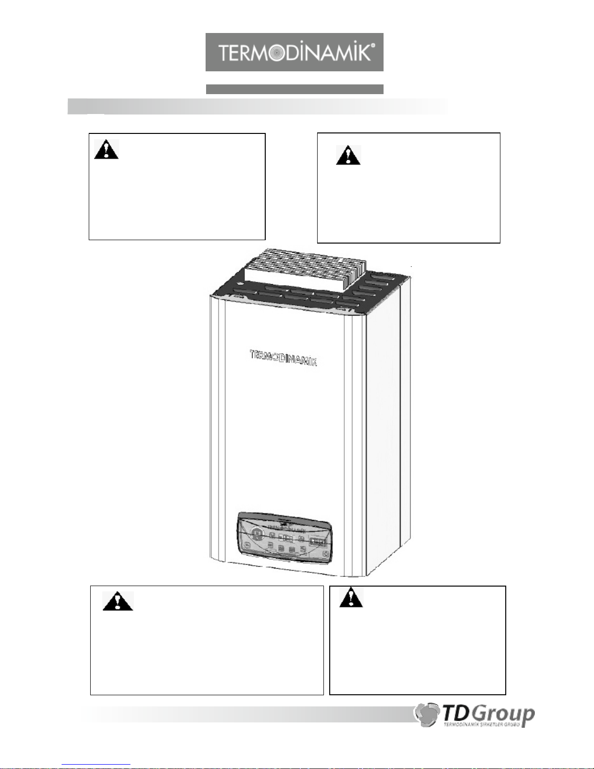
WARNING
• Assembly of an el ectrical equipment must be
performed by qualifie d and certified electrician
(DIN VDE 0105).
• Gener al rules of thu mb related to working with
electricity must be fo llo we d. For instance:
Electricity must be shut down befo re any work
begins.
WARNING
If instruction s in this manual are not
followed, a serious fire and/or
explosion may ocur, resulting with
personal injury, property damage,
even death.
WARNING
:
Improper installation, adjustment,
alteration, service, or maintenance can
cause injury or property damage. Refer to
this manual for assistance or additional
information. Consult a qualified installer,
authorized service, or the electric utility.
FOR YOUR SAFETY
•
Do not store or use gasoline or other
flammable vapors and liquids in the
vicinity of this or any other appliance.
•
Installation and service must be
performed by a qualified installer,
service agency or the electric utility.
H E A T I N G S Y S T E M S
ENTRY
GENERAL
....................................................................................................... 3
1 INTRODUCTION
..................................................................................... ...4
2 GENERAL FEATURES
......................................................................................
5-6
3 COMPONENTS (6-9-12 kW)
...................................................................... 7
4 COMPONENTS (18-24-30-36 kW)
............................................................. 8
5 ASSEMBLY & STARTUP
................................................................................... 9
6 MOUNTING ON THE WALL
.................................................................... 10
7 CONNECTIONS OF THE BOILER
............................................................. 11
8 SYSTEM CONNECTION DETAILS
............................................................ 12
9 ELECTRICAL CONNECTIONS
.............................................................
13-15
10 WATER FILLING THE SYSTEM
............................................................... 16
11 THE FIRST INSTALLATION OF THE BOILER
............................................ 17
12 SAFETY
................................................................................................. 17
13 TERMODINAMIK DIGITAL ELECTRICAL BOILER TECHNICAL DATA…….18
14 DIGITAL BOARD USER’S GUIDE
.......................................................... 19
141. GENERAL VIEW OF THE BOARD
................................................. 19
142. BUTTONS
............................................................................. 19-20
143. DISPLAY AND INDICATORS
............................................................. 21
144. SET VALUE ENTERANCE
............................................................. 21
145. TURN ON / TURN OF
................................................................ 22
146. TIME SETTINGS.
........................................................................ 22
147. CHILDREN LOCK
........................................................................ 22
148. ROOM THERMOSTAT
..................................................................... 22
149. TIMER MENU
............................................................................ 23
1410. TIMER OPERATING
.................................................................. 25
1411. USER’S PARAMETERS
............................................................... 25
1412. ERRORS / NOTICES
................................................................. 26
CONTENT

H E A T I N G S Y S T E M S
3
1.
Electrical boiler is never worked without water. Do it only when absolutely necessary
and do it only under full supervision of service person and do it fast. When out of service
for long period of time (such as summer season), do not empty the water.
2.
Use only warm water and soap to clean external panels.
3.
Compliance with instructions in this user manual keeps your boiler efficient and
running smoothly.
4.
Termodinamik Electrical Boiler has been delivered to you all checked and adjusted at
the factory, ready to run. The service technician who will come for the start-up will
perform fine adjustments and inform you. Please do not interfere with adjustments without
the knowledge of service technician.
5.
Never run the boiler without water. You will cause serious damage to resistance.
6.
We recommend you read your manual carefully and keep it at a safe place for referral
later.
Important:
All supply equipment, installation, approvals, permits, inspections, etc. are the responsibility of
the owner of this electrical boiler. Consult your local authorities for regulations specific to your area.
TERMODINAMIK DIGITAL ELECTRICAL BOILER OPERATION MANUAL
This manual belongs to user and should be kept after assembly for referral later.
GENERAL

H E A T I N G S Y S T E M S
4
2 GENERAL FEATURES
Your electrical boiler has been subjected to various safety tests during manufacturing
processes.
Your electrical boiler has been insulated all around with aluminum foiled fiberglass insulation
and energy losses have been minimized. Surface of internal sheet metal chassis parts are
protected with high quality primer paint, external surfaces are protected with electrostatic
epoxy-polyester powder paint against the corrosion.
Closed expansion tank is a standard item with your boiler. It maintains safety of your water
systems against the pressure variations.
When the user sees that the pressure drops below 1 bar, must interfere personally and fill
water into the system. Your boiler has a water pressure switch for safety to shut off the entire
system in case of water pressure drop to 0,6 bars (lack of water) to prevent parching of
resistances. (Boiler is now in off position and water must be added and on button must be
pressed to restart).
The water heated in your boiler passes through plat e heat exchanger before goes to
radiators and heats your domestic use water to provide you with hot water.
Your boiler has been checked at the factory and ready to run. Please read this user manual
first, before using your boiler and keep it at a safe place for later referral.
Your boiler will serve you for a long time with maximum efficiency as long as
recommendations here followed.
1. INTRODUCTION
FAILURE TO FOLLOW THE INSTRUCTIONS IN THIS MANUAL MAY RESULT IN DEATH,
SERIOUS BODILY INJURY AND/OR PROPERTY DAMAGE. THOROUGHLY READ ALL
INSTRUCTIONS BEFORE YOU ATTEMPT TO INSTALL, OPERATE OR MAINTAIN THIS BOILER.

5
H E A T I N G S Y S T E M S
2. GENERAL FEATURES
QUITE: It is electrical, by nature it is quite.
SAFE: Your boiler has a water pressure switch for safety to shut off the entire system in
case of water pressure drop to 0.6 bar. (Boiler is now in off position and water must be
added and on button must be pressed to restart).
Thermostat is set to 80oC max. When this is reached electrical current to resistances is shut
off. If this thermostat malfunctions, there is a limit thermostat set for 90°C.
Digital manometer displays water pressure all the time. If pressure reaches 2.5 / 3 bar safety
valve opens, pressure is released and some water discharged.
ECONOMY: High quality subcomponents enable use of electricity as a fuel with highest
possible efficiency.
Provides independent heat. Heat as much as you want, when you want. Pay as much you
heat.
Fully programmable and has timer for your automatic setting.
One unit provides you with heat & hot water.
Electronic control card is modulated for economy.
EASY TO USE: One touch button safe & easy operation.
HIGH OUTPUT: Electricity as a fuel has high efficiency with very minimal loss. Therefore
your boiler has naturally high efficiency.
ENVIRONMENTALLY FRIENDLY: The fuel is electric. Therefore, no flue gas, no chimney,
no dirt of carbon-based fuels create.
WIDE SPREAD SERVICE NETWORK: Termodinamik has wide spread established service
network all over Turkey, ready to respond when you need.
LONG LASTING: Your boiler is protected against effects of corrosion.
WARRANTY: Your boiler has 2 years warranty against the defects resulting from
manufacturing. Defected parts are replaced with new ones.
H E A T I N G S Y S T E M S
PACKING
: External surface your boiler is painted sheet metal with protective film to prevent
stretches during handling and assembly. Please peel off the film before start-up. Your boiler
has been packed in a corrugated box for safe transport.
6
H E A T I N G S Y S T E M S
7
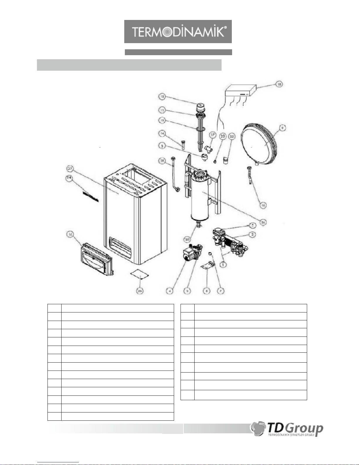
3. BOILER COMPONENTS (6-9-12 kW MODELS)
1 3 WAY VALVE HYDRO BLOCK (IN-OUT)
2 PLATE HEAT EXCHANGER
3 PUMP BODY
4 PUMP COVER
5 3 WAY VALVE MOTOR
6 WATER PRESSURE SWITCH
7 PUMP RING
8 PUMP MOUNTING PLATE
9 EXPANSION TANK (7 Liters)
10 COPPER PIPE (PUMP BOILER IN)
11 HEATING RESISTANCE
12 RESISTANCE GASKET
13 RESISTANCE PROTECTION PLASTIC COVER
14 THERMOCOUPLE PIPE
15
EXPANSION TANK HOSE
16 DIGITAL PANEL
17
AUTOMATIC SAFETY VALVE
18 RELAY BOX
22 AUTOMATIC AIR PURGER
23 MANUAL AIR PURGER
24
TERMODINAMIK LABEL
25
PRODUCT LABEL
26 INNER TANK BODY
27
EXTERNAL BODY (CASING)
28
BOILER EXIT PIPE

8
H E A T I N G S Y S T E M S
4. BOILER COMPONENTS (18-24-3 0-36 kW MODELS)
15 THERMOCOUPLE PIPE
16
EXPANSION TANK HOSE
17 DIGITAL PANEL
18
AUTOMATIC SAFETY VALVE
19 RELAY BOX
23 AUTOMATIC AIR PURGER
24
BOILER EXIT PIPE
25
TERMODINAMIK LABEL
26
EXTERNAL BODY (CASING)
27
PRODUCT LABEL
1 3 WAY VALVE HYDRO BLOCK (IN-OUT)
2 PLATE HEAT EXCHANGER
3 PUMP BODY
4 PUMP COVER
5 3 WAY VALVE MOTOR
6 WATER PRESSURE SWITCH
7 PUMP RING
8 PUMP MOUNTING PLATE
9 EXPANSION TANK (7 - 10 Liters)
10 INNER TANK BODY
11 COPPER PIPE (PUMP BOILERIN)
12 HEATING RESISTANCE
13 RESISTANCE GASKET
14 RESISTANCE PROTECTION PLASTIC COVER

H E A T I N G S Y S T E M S
9
Your boiler must be hung on a wall firmly and rigidly. Water scale should be used for
fine alignment. Minimum clearance and from the floor should be 50 cm, distance from
the ceiling 40 cm. Connections must be done as shown. Not even drop of water
should be permitted.
Do NOT install the boiler in a humid environment such a bathroom.
If the boiler to be installed in an outdoor environment, it must be under/in protective
cover.
All pipes must be connected as shown in the picture No drop of water must be
allowed to leak out.
Please comply with assembly instructions given on page 12 in order to obtain hot
water during summer months.
Pump, boiler ―to & return‖ pipes, safety ―to & return‖ pipes must be installed without
causing any air pockets. Where air bubbles possible, air discharge system must be
installed.
After completion of assembly, system must be flashed twice. This will achieve cleaning
of inside of pipes.
DO NOT FORGET to close ―in & out‖ valves of boiler when flashing the system.
Outside pipes must be insulated to minimize heat loss.
We recommend use of radiator return valves at the returns instead of standard
radiator valves.
Use of decalcification equipment is recommended at the entrance of domestic water
to prevent calcification.
During mounting of the boiler, please use all elements provided to make sure rigid
assembly on the wall.
All wiring and electrical connections must be done in accordance with TSE regulation
(in Turkey), or local codes (other countries).
5. ASSEMBLY & START-UP
Water temperature over 52°C can
cause several burns instantly or
death from scalds. Children,
disabled and elderly are at highest
risk of being scalded. Feel water
before bathing or showering.
Temperature limiting valves are
recommended.

H E A T I N G S Y S T E M S
10
Explanations:
1 – Minimum distance to ceiling should
be 400 mm to be able remove the
resistance when necessary.
2 – Please make sure that the wall
boiler is mounted rigid and strong.
Bolts hold tightly and wall is strong
enough to carry the boiler.
3 – Hot water to radiators
4 – Domestic use hot water out
5
– Domestic cold water entry
6
– Return from radiators
6. MOUNTING ON THE WALL

H E A T I N G S Y S T E M S
11
1
Radiator return ¾‖
2
Cold water entry ½‖
3
Cold water exit ½‖
4 To radiator ¾‖
Height : 723 mm
Width : 427 mm
Depth : 354 mm
Radiator in & return (3/4”)
Domestic water in & return (1/2”)
YOUR BOILER MUST BE INSTALLED ACCORDING TO ―ASSEMBLY INSTRUCTIONS‖ PROVIDED IN THE
BOX. THERE MUST BE 40 CM CLEARANCES FROM THE CEILING TO FACILITATE ASSEMBLY &
REMOVAL OF RESISTANCES WHEN BOILER MOUNTED.
7. CONNECTIONS OF THE BOILER
723

H E A T I N G S Y S T E M S
12
8. SYSTEM CONNECTION DETAILS
!
Please use ball valve for
the boiler – main water line connection
in order to facilitate maintenance and service.

H E A T I N G S Y S T E M S
13
9 ELECTRICAL CONNECTIONS
NO
GROUND
SAFETY
THERMOSTAT
Please make sure that boiler is grounded
PUMP
3 WAY
VALVE
ROOM
THERMOSTAT
6 - 9 kW (220 V)
PUMP
PUMP
3 WAY
NEUTRAL
NEUTRAL
PHASE
WINTER
SUMMER
NEUTRAL
NEUTRAL
PUMP
HEATER
HEATER
HEATER
HEATER
HEATER
HEATER
DATA CABLE

14
H E A T I N G S Y S T E M S
Please make sure that boiler is grounded

H E A T I N G S Y S T E M S
15
Please make sure that boiler is grounded
(380 V)

16
H E A T I N G S Y S T E M S
1. Open the filling valve connected to radiator return valve to fill the system with water.
Enclosed ―3/4 T’ ―mini-ball valve provided for water filling & discharge purposes.
2. During startup (the first run), please fill water until the boiler reaches 2.5 / 3 bar and
water comes out of safety bar in order to remove all air pockets in the system. After
completion of air removal, please discharge water out of the system until 2 bar is read
on digital manometer.
NOTE: Fill more water into system if manometer reads 1.0 bar or less. It is always a better
practice to add water into system the boiler is cold.
Please try to keep domestic hot water temperature below 52oC to prevent
serious burns.
Before you take a shower, feel the temperature of the water first.
It is also recommended use of temperature limiting valves.
10 WATER FILLING THE SYSTEM

17
H E A T I N G S Y S T E M S
1.
Connect boiler phase and neutral power cables than check the connections. Do not
open boiler until you are sure to be connections. Device contains mechanical high
heat circuit breaker system therefore connections of the phase, neutral and ground
connection is very important. System operation and security depends on the correct
links.
2.
Pump water the system and give energy. While system is cold, take the air of the
system. After all controls of the system, if there is no problem to work the boiler in
1.5 bar.
1
— Leak current relay:
It disconnects the power line, if a leak higher than 30 milliamps and longer than 1 micro
second. (30 milliamps is not noticeable by human sense).
2
— Mechanical high limit thermostat:
If resistance can not be controlled due to an unexpected fault, leak current relay will switch
on at 90oC and power will be cut completely.
3
— Digital high limit:
If mechanical high limit mentioned above is not activated by some reason, digital high limit
thermostat will switch on at 90oC and bring the system to ―off‖ position.
4
— Pressure control system:
Digital sensors will not allow pressure drop below 1.0 bar and get resistance damaged due to
lack of water.
5
— Zero crossing circuit: (with three phase models only)
Eliminates voltage fluctuations on the three phase system of the house by bringing triac
circuits online balanced according to zero incoming angle angles of phases.
6
— Random run program:
11 THE FIRST INSTALLATION OF THE BOILER
12 SAFETY

H E A T I N G S Y S T E M S
18
Resistance will come on & off line randomly, after the system has reached to set. This will
extend the life of resistances.
7
— Freeze protect:
If the water degree inside the boiler decreases fewer than 6 oC, the circulation pump stars
and protect the boiler from freezing.
8
— Pump protect:
If the circulation pump does not start, pump starts every day for 1 minute protecting the
system against rust and calcification.
9
— Children Lock:
Pressing the UP and ESC buttons with the same time for 3 seconds, Boiler locks the buttons
until pressing the UP and ESC buttons with the same time for 3 seconds.
13 TERMODINAMIK DIGITAL ELECTRICAL BOILER TECHNICAL DATA
MODELS >>
DEK 6
DEK 9
DEK 12
DEK 18
DEK 24
DEK 30
DEK 36
CAPACITY
kW 6 9 12 18 24 30 36
kcal/h
5160 7740
10320
15488
20650
25813
30975
Working pressure
bar 2 2 2 2 2 2 2
Water volume
L 4,2 4,2 4,2 24 24 24 24
Radiator ―to‖ – ―return‖
inch ¾
¾
¾
¾
¾
¾
¾
Domestic water ―to‖ –
―return‖
inch ½
½
½
½
½
½
½
Power supply connection
cable
qnty/mm
2
2x6
2x10
4x2.5
4x4
4x6
4x10
4x10
Nominal voltage
Volt
220
220
380 380
380
380
380
Fuse Amp
32
(Monophase)
50
(Monophase)
20
(Three-phase)
32
(Three-phase)
40
(Three-phase)
50
(Three-phase)
63
(Three-phase)
Weight, gross
kg 41 41 41 67 67 67 69
Dimensions
(h x w x d)
mm
723 x 427 x 354
*Power supply connection cable cross sections are calculated according to the line length of
15
meters.

H E A T I N G S Y S T E M S
19
141 GENERAL VIEW OF THE BOARD
142 BUTTONS
START BUTTON
Turns the boiler ON
STOP BUTTON
Turns the boiler OFF
ENTER BUTTON
Value is used to access
ESC BUTTON
Cancel the entered value access
14 DIGITAL BOARD USER’S GUIDE

19
H E A T I N G S Y S T E M S
TIMER ON BUTT
CLOCK SET
UP / DOWN BUTTONS
To change the values entered and circulation between the menu
BUTTON
Using the adjust the time
RAM BUTTON
Using to timer programming
ON
Using to set the boiler timer mode
DOMESTIC USE WATER SET / PROGRAM BUTTON
Entering the domestic use water value
RADIATOR WATER SET / PROGRAM BUTTON
Entering the radiator water value
WINTER / SUMMER MODE CHOSE BUTTON
Setting the boiler for summer and winter mode
TIMER PROG
20

H E A T I N G S Y S T E M S
21
143 DISPLAY AND INDICATORS
Display of the boiler. Any kind of value entry and
follow up can be made through this screen.
INDICATORS
HEAT LEVEL INDICATOR
Shows boiler’s working heat steps
SITUATION INDICATOR
Shows active parts and working positions. From up to down buttons are;
pump radiator active, domestic use water active and alarm activations.
144 SET VALUE ENTERANCE
For entering the domestic use water set value enter the
button. You can see
the flashing of the domestic use water set value at the display.
For entering the radiator water set value enter the
button. You can see the
radiator of the use water set value at the display.

H E A T I N G S Y S T E M S
22
Enter the value by up/down button than accept processing button. For
returning the old value use button.
145 TURN ON / TURN OFF
Set boiler winter or summer mode by button. Turn on boiler
button. You can turn off boiler button.
146 TIME SETTINGS
Push the button. Clock value is going to activate at the display. Enter the hour
values by up/down button than accept values by button. Minute value
is going to activate. Again enter the minute value by up/down button and accept
the value button.
147 CHILDREN LOCK
Pushing the (up) and (esc) button same time for 3 seconds, boiler
locks the buttons. For unlocking the boiler repeat the same p r o c e d u re .
When boiler is locked you can
key sign at the d i s p l a y
148 ROOM THERMOSTAT
When the thermostat sends signal boiler stops heating and waits for room cool. Th is
process shows sign at the display.

H E A T I N G S Y S T E M S
23
149
TIMER MENU
149.1
TIMER PROGRAMMING
Push the button. At the display you see;
TIMER MENU. You can chose TIMER PROGRAM by up/down buttons than accept
election by button. At the display you see;
Entrance menu of the TIMER MENU. Push button to activate TIMER ON. You can
see activation when time hour part appears dark. Set the hour between 023
by (up/down) button then accept hour button. After hour entrance
minute part activates . Enter between 055 minutes by (up/down)
button then accept button.

H E A T I N G S Y S T E M S
24
TIMER OFF time is activated. Repeat the same procedure as TIMER ON. After TIMER OFF
time setting, TIMER SET value will be activated. That Value shows which time period of
boiler heats TIMER ONOFF
For new time period push
button. New period P page opens. If the conflict
between time periods, display gives ―wrong value‖ notice
149.2 DELETING ALL TIMER VALUES
Chose DELETE ALL at the TIMER PROGRAM menu then push
button. Boiler asks
YES/NO question of consent. Push
than chose YES and push
button.
At the display you see COMPLETED message. That means you deleted all timer values you
have entered
149.2 ECO TIMER
Eco timer values are tested by factory to meet the demands of normal users. Those
settings are adjusted to be economic. Eco timer value entrance causes deletion of the past
entered timer values.
For Eco Timer enter;
From TIMER PROGRAM menu chose ECO TIMER than push
button. Boiler asks
YES/NO question of consent Push
than chose YES and push
button.
At the display you see COMPLETED message. That means entered ECO TIMER menu.
ECO TIMER time opening;

H E A T I N G S Y S T E M S
25
1410 TIMER OPERATING
Push button. If you have programmed any timer before, the light near the
button will flash. Those programs shown at the display P1, P2, ... If use is at the
programmed timer zone time part, P sign will flash. For leaving the timer mode push
TIMER ON button again.
1411 USER’S PARAMETERS
This parameters allows customization device for user’s. For entering the user’s parameters
page;
While device CİHAZ KAPALI mode button 5 seconds. Then you see
PARAMETER settings menu.
From this menu make entrance by button then accept entrance by
button. button exits user from parameter menu.
Parameter list;
P1: Language chose
PROGRAM

H E A T I N G S Y S T E M S
26
This is Language select parameter. It changes display language TURKISH or ENGLISH. If
user enters 0: display language sets TURKISH, 1: enter display language sets ENGLISH.
P2: Display light
If this parameter chose ―Auto Back‖ YES, while device working normal mode without
pushing any button, device shut down display light after 3 minutes later. NO case of
choosing, the display remains open continuous light.
P3: Power failure
If this parameter chose YES, device goes working after electricity interruption goes away.
When device TURN OFF before electricity interruption, device still TURN OFF If electricity
come back. If NO parameter selected and electricity interruption goes away device
TURNS OFF.
1412 ERRORS / NOTICES
1412.1 ERRORS
Boiler (down prob) error
This error accures If boiler inside water sensor (prob) breakdown. This sensor is installed to
pipe . This error turns off boiler.
Domestic use water prob error
This error accures If domestic use water sensor (prob) breakdown. This sensor is dipped
type of boiler. This error turns off boiler.
Boiler (down prob) error
This error accures if boiler inside water sensor (prob) breakdown. This sensor is dipped
type of boiler. This error turns off boiler.
Over Heating
If boiler inside water temperature reaches 90oC, digital high limit starts up and give over
heat error than cuts the electricity connected to resistors. When boiler temperature
decrease under 90oC system stops error and starts working again.

H E A T I N G S Y S T E M S
27
Low Pressure (Mechanic)
If pressure of the boiler decreases under 0.6 bar you see that error. This error turns off
boiler.
1412.2 NOTICES
Low Pressure
If pressure of the boiler decreases under 1 bar you see that notice. This notice does
not turns off boiler.
Set Timer
If user push TIMER ON button without setted timer, system gives Set Timer notice
Device Summer Mode
If device works in summer mode and user push the TIMER ON button, boiler gives that
notice. Take boiler to winter mode with summer/winter button than push TIMER ON
button.
Device Timer Mode
When boiler is at timer mode (TIMER ON flash is indicating) and user want to select
summer mode by summer/winter button that alert will appear. Exit boiler timer mode by
pushing the TIMER ON button than take boiler to SUMMER mode

WARRANTY COMPLIANCE PARTICULARS
This warranty does not cover damages arising from use of the device outside its intended purpose. However,
in the following cases the device can be handled outside the warranty, for a certain fee:
- Wrong placement, physical or chemical factors, failures and damages originating from shipment and
storage conditions. Failures and damages originating from fire, lightning strike, flood and natural disasters.
Freezing due to climate conditions. Systems not compliant with the fixture coupling instructions and
recommendations in the operation manual.
- Failures and damages that arise during loading, unloading and handling after the customer takes delivery
of the product.
- Failures and damages originating from user errors.
- Failures and damages originating from low or high power network voltage, fluctuations or irregularities in
power network frequency, electrical fixture errors, or operation of the device on a voltage level different than
the value specified on the product label.
- Scratches on the painted surfaces.
- Products for which warranty certificate or product purchase invoice cannot be presented to the authorised
service provider of our Company.
- Damages originating from the user's failure to conduct necessary periodic maintenance and controls.
- Problems with any device whose initial start-up is not performed by an authorised service provider or any
repairs or modifications,
annual general maintenance and cleanings, or periodic maintenance and cleanings which are not performed
by an authorised service provider.
- Any failure in the device should only be handled by TERMODINAMIK AUTHORISED SERVICE
PROVIDERS authorised by our Company. Otherwise the warranty will be void.
- In case the product label or the serial number of the product on the Warranty Certificate is damaged the
warranty will fall void.
- Devices whose factory standard configuration is modified.
- Failures and damages originating from wrong capacity, fuel or model choice.
- Product installation should be handled by the Contracting Firm, and the initial start-up should only be
handled by TERMODINAMIK authorised service providers. After purchasing the product please consult the
service providers booklet provided with the product and contact the closest TERMODINAMIK authorised
service provider to your location. Device failures originating from failure to have initial start-up performed by
an authorised service provider will be handled outside the warranty.
- In case you become aware of a failure in your device please consult the operation safety section of the
Operation Manual. In case the failure does not improve do not let anybody interfere with the device and
contract the TERMODINAMIK authorised service provider responsible for your area.
- In case the authorised service provider feels any doubt regarding the warranty term, product purchase
documentation or service slips and the initial start-up form must be presented upon request of the service
provider.
- The warranty shall only be valid in the term defined on the Warranty Certificate and only for the failure in
the product (the boiler). No other right or compensation shall be claimed under the warranty for any failures
outside the product, e.g. in fixture lines, radiator, fuel tank, pipe fitting materials, flue problems, radiator
valves, etc.
- Please ask for and keep one copy of the failure form filled by the service provider. This document will be
useful for you in case of any problem you might experience with your device in the future.
- Only original equipment should be used in device installation and spare part replacements.
- Have your seller certify the relevant parts in your warranty of your product when you buy it.
- The dealer, seller or agency that sells the product to the customer is responsible for delivering of warranty
to the customer.

H E A T I N G S Y S T E M S
Kemalpaşa OSB Mah. 80. Sokak No:10 KEMALPAŞA-İZMİR-TURKEY
Tel: +90 (232) 877 12 12 Fax: +90 (232) 877 08 67
www.termodinamik.com.tr
 Loading...