

TERMET ECOCONDENS SILVER PLUS-25, ECOCONDENS SILVER PLUS-20, ECOCONDENS SILVER PLUS-35 Instruction Manual
COMBI BOILERS
ECOCONDENS SILVER PLUS -20
ECOCONDENS SILVER PLUS -25
ECOCONDENS SILVER PLUS -35
SYSTEM BOILERS
ECOCONDENS SILVER PLUS -20
ECOCONDENS SILVER PLUS -25
ECOCONDENS SILVER PLUS -35
1450

DEAR CUSTOMER
Congratulations on having chosen te rmet product.
We are glad that we can offer you modern, economical and environmentally friendly product, meeting particularly high requirements of European Standards.
Please read this instruction manual carefully as the knowledge of service rules and manufacturer’s recommendations are the conditions of reliable, efficient and safe
operation of the appliance.
Please keep this instruction manual for the whole operation life of the boiler.
We wish you satisfaction in using our product.
termet
IMPORTANT INFORMATION
• Read the instruction manual before you perform the installation and operation of the boiler.
• This instruction manual is an integral equipment of the boiler. It should be kept through the whole operation life of the boiler and carefully read. It contains all the
information and warnings for safety during installation, use and maintenance to be followed.
• The boiler is complicated appliance as it contains numerous precise mechanisms.
• Reliable operation of the boiler depends mainly on appropriate performance of systems that boiler cooperates with such as:
- gas system,
- flue gas-air system,
- central heating system,
- domestic hot water system.
• Flue gas - air installation for C type boilers should be made of separately approved and introduced on the market gas - air system. Adapters connecting the boiler
with a pipe system must have a measuring points. Flue gas – air system must meet the specifications set out in section 3.8 of this manual.
• Flue gas - air system must be tight. Leaks on the connections of flue gas pipes can result in flooding of the boiler by condensate. Manufacturer is not liable for
damage and malfunction of the boiler arising out from above mentioned reason.
• Installation of the boiler should be performed only by a qualified person1). Make sure that the installer has confirmed in writing the tightness of the gas
installation had been checked after connecting the boiler to the system.
• Boiler may be installed and operated only in a room where all building works have been completed. It is not allowed to install and operate the boiler in a room
where building works are still in progress.
• The cleanliness of air in a room where the boiler will be installed must meet the same requirements as for rooms designer for people.
• There should be installed appropriate filters on a central heating system and gas system . Filters are not included in a basic boiler equipment.
• An example of connecting a boiler to these systems is presented on fig. 3.5.1.
• All defects caused by lack of filters on central heating or gas supply will not be repaired under guarantee.
• Central heating system must be thoroughly cleaned and rinsed, the procedure is described on p.3.5.2.
• To avoid malicious calcification process of flue gas - water heat exchanger and also for reduce a risk of other items damage, there should be:
- the proper water preparation in C.H. circuit according to p.3.5.2, Proper water parameters in C.H. system allows for long term operation maintaining its high
efficiency, what leads to lower costs of gas consumption,
- proper tightness of central heating system ensured by avoiding frequent refilling it with water,
• Complaints caused by gas-water heat exchanger calcification will not be repaired under guarantee.
• The initial start-up of the boiler as well as its repairs, adjustments and maintenance works must be performed only by AUTHORISED SERVICE COMPANY.
• The boiler must be operated only by an adult.
• Do not do any repairs and modifications by yourself.
• Do not cover any ventilation grilles.
• Do not keep in the vicinity of the boiler any containers with flammable, aggressive and corrosive liquids and other similar substances.
• Any failures that are result of operation discordant to recommendations included in this instruction manual cannot be subject to warranty claims.
• Manufacturer is not responsible for any failures being the result of faults during the process of installation and inobservance the regulations and instructions given
by the manufacturer.
• Complying with recommendations given in this instruction manual ensures a long, reliable and safe operation of the boiler.
NOTICE!
When you smell gas:
- do not use any electrical switches that could cause any spark,
- open the door and windows,
- shut down the main gas valve,
- immediately contact your gas supplier.
In case of any failure you should:
- disconnect the boiler from a power source,
- shut down the gas supply valve,
- cut off a water supply and drain a water from the boiler and whole central heating system as well (when there is any risk of
freezing of the system),
- drain the water from the system in any case of leakage that could cause a flood ,
- contact the nearest AUTHORISED SERVICE COMPANY or the producer.
1)
‘Qualified person’- person that has all required technical qualifications in an area of doing all the works necessary to connect appliances to the gas mains, central heating
system and flue gas duct, accordingly to local regulations.
ECOCONDENS SILVER PLUS
ISU-646:2016/GR-H str.1
WARNING!
Operational instruction during the start-up of the condensing boilers
The instruction should be used after every draining water in the boiler
i.e. during the renovation of C.H. installation or repair of the boiler.
Read carefully the instruction manual before filling the boiler with water
1. Fill the heating circuit with water and vent the radiators before start.
2. Check the correctness of connection the electrical cords of boiler (network 230 V/50 Hz) to the network:
L- brown; N – blue; PE – yellow-green. Do not change the cords L and N!
In case of change the cords, the boiler will enter in failure state, on display will occur an error code E01.
Mark the cords properly when connected directly to the electrical box, to eliminate the possibility of
exchange.
3. Close the gas cut-off valve!
4. Open valves which cut-off the boiler from C.H. circuit.
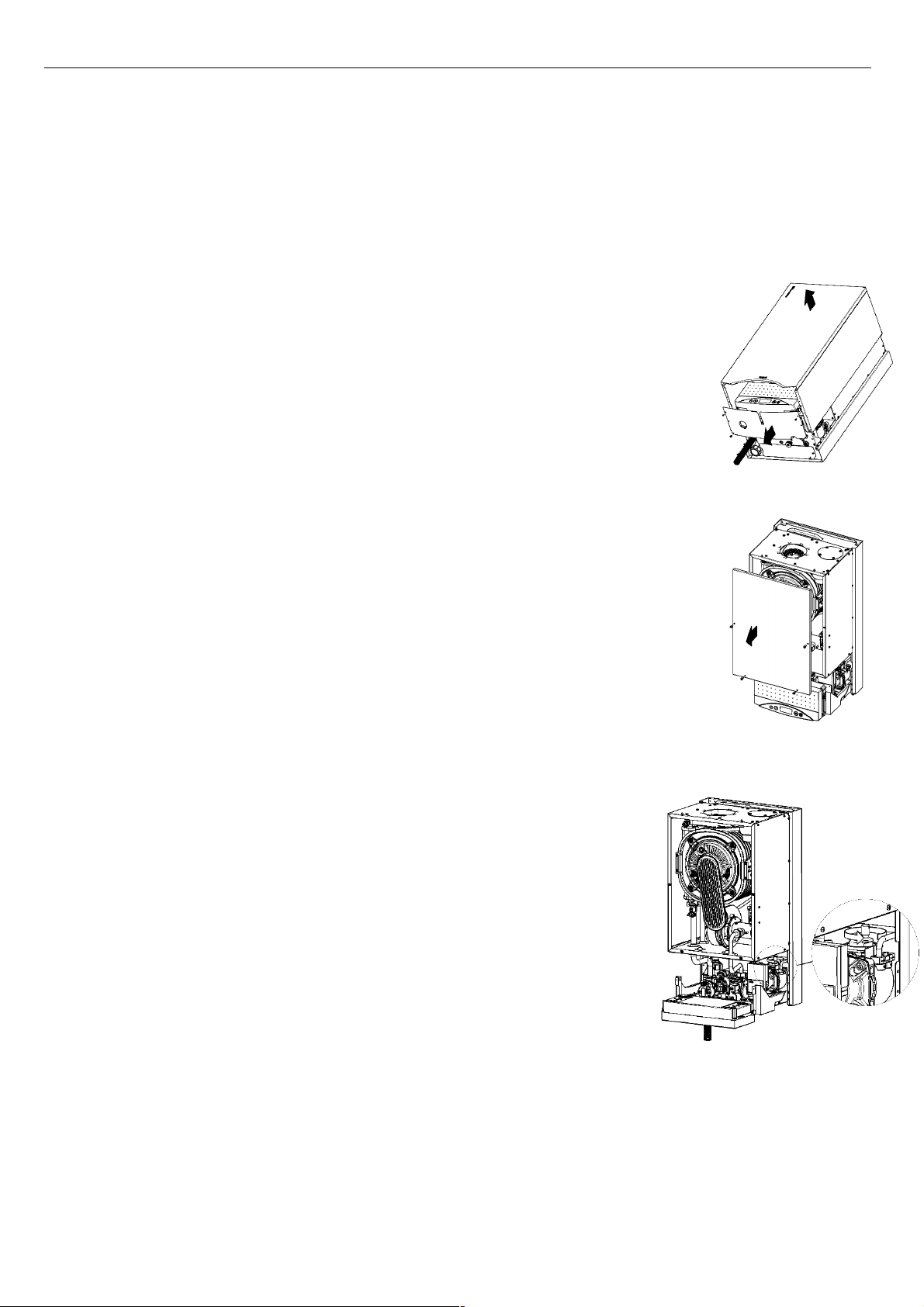
5. Remove the front cover of the boiler by unscrewing the relevant fixing screws (fig. 1).
6. Remove the front cover of the combustion chamber (fig. 2).
7. Loosen the stopper on the automatic air-vent of the pump. In order to protect the pressure transducer from
water, point the outlet of stopper to the right (fig. 3).
8. Turn on the device. Wait until the start procedure, testing the internal subassembly’s and ventilating the
combustion chamber will end (time about 10 – 30 sec.)
9. Fill the boiler with water by using the filling valve (in case of system boilers – the filling valve is mounted on
C.H. installation, in case of combi boilers – the filling valve is on the boiler’s equipment – see p.3.5). Open
the filling valve slowly to protect the boiler’s and the C.H. installation’s components against the results of a
hydraulic shock.
10. During filling the boiler with water control the pressure by using the analogue manometer mounted on the
boiler’s front cover or the electronic manometer by reading the pressure from display of the controller
(depending on the boiler’s type). Shut off the filling valve after reaching the pressure of 1,0 – 1,5 bar.
Note: in some models of boilers, after end of the start procedure, the “support the venting of boiler” function
starts. This function is signalized on the controller display by “Po” and lasts 3 min. Start the “support the
venting” function requires the water pressure above 0,5 bar, that’s why during this procedure check and fill
up the water pressure in the boiler, it is best to maintaining it the range of 1,0-1,5 bar.
11. Set the operating mode on WINTER according to the boiler instruction. If to the boiler controller has been
connected the room thermostat than increase the desired temperature; the boiler should start operating in
C.H. mode.
12. Because the gas valve outside the boiler is closed, the boiler will stop operate (E01 error code – a lack of
gas). It allow for continuous pump operation and for removal of the air flowing in with water from the
installation and for continuous water flow through the heat exchanger. Leave the boiler in this state for 2-3
min.
13. Delete E01 code by “reset” button and set the boiler controller on pressure reading mode (in version without
an analogue manometer). During the first days of boiler operating it is recommended to set the water
pressure in C.H. circuit on 1,8-2,0 bar. It will facilitate the work of the air-vent on the boiler pump and on the
components of C.H. circuit. **
14. Unscrew the gas valve and delete E01 code again.
15. Set the desired operating parameters of the boiler according to the instruction manual. ***
16. Check the water pressure in C.H. circuit and if it’s necessary fill the pressure up to the right level.
Fig. 1
Fig. 2
* Depending on the size of C.H. circuit time of filling the boiler with water can be different. It is recommended to
earlier fill the C.H. installation with water.
** In home C.H. circuits the nominal operating pressure should be set on 1,2-1,6 bar.
*** Note! The boiler is factory set on operating in the radiator heating. In case of the floor heating, the boiler control
system shall be adapted to other operating parameters. This action is performed by Authorized Service Company.
Fig. 3

ECOCONDENS SILVER PLUS
1. INTRODUCTION .......................................................................................................................................................................................................................................................................... 3
2. BOILER DESCRIPTION .................................................................................................................................................................................................................................................................. 3
2.1. T
ECHNICAL SPECIFICATION
2.1.1. Technical features...................................................................................................................................................................................................................................................... 3
2.2. D
ESIGN AND TECHNICAL SPECIFICATIONS OF THE BOILER
2.2.1. Main units of the boiler.............................................................................................................................................................................................................................................. 3
2.2.2. Technical data ........................................................................................................................................................................................................................................................... 5
2.3. P
ROTECTION EQUIPMENT
2.4. O
PERATION DESCRIPTION
2.4.1. Way of heating the water for central heating system ................................................................................................................................................................................................ 6
2.4.2. Temperature regulation dependent on external temperature ................................................................................................................................................................................... 6
2.4.3. Method of D.H.W. heating in combi boilers ............................................................................................................................................................................................................... 7
2.4.4. The way of heating the water in system boiler ECOCONDENS SILER PLUS cooperating with domestic water tank. ................................................................................................... 7
2.4.5. Operation of the pump with adjustable speed. ......................................................................................................................................................................................................... 8
3. BOILER INSTALLATION ............................................................................................................................................................................................................................................................... 9
3.1. R
EQUIREMENTS OF BOILER INSTALLATION
3.1.1. The regulations on the water installation, gas and the flue gas system ..................................................................................................................................................................... 9
3.1.2. Regulations related to the room ................................................................................................................................................................................................................................ 9
3.1.3. Requirements for electrical installation .................................................................................................................................................................................................................... 9
3.2. P
RELIMINARY CHECK ACTIVITIES
3.3. M
OUNTING THE BOILER ON THE WALL
Fig. 3.3.1 Installation dimensions of boiler ECOCONDENS SILVER PLUS ............................................................................................................................................................................. 10
3.4. C
ONNECTION TO THE GAS INSTALLATION
3.5. C
ONNECTION OF THE BOILER TO A WATER SYSTEM OF CENTRAL HEATING
Fig. 3.5.1 Boilers installation requirements ........................................................................................................................................................................................................................ 11
3.5.2 System cleaning and water treatment for the C.H. filling. ......................................................................................................................................................................................... 11
3.6. C
ONNECTION OF THE BOILER TO A DOMESTIC HOT WATER SYSTEM
3.7. C
ONDENSATE OUTLET
3.8. F
LUE GAS OUTLET
3.8.1. The ways of mounting adapters (elbows connection) to the boiler type .................................................................................................................................................................. 12
3.8.2. Horizontal outlet of air- flue system through the wall or on the roof ....................................................................................................................................................................... 13
3.8.3 Vertical outlet of air- flue gas system through the roof ............................................................................................................................................................................................ 13
3.8.4 Connecting to a common chimney duct system, consisting of a duct for air inlet and flue gas outlet duct ............................................................................................................... 13
3.8.5. Flue gas air outlet and air inlet by two separate tubes ........................................................................................................................................................................................... 14
3.8.6 Reduction of the maximum length of the air-flue system by changing the flow direction ......................................................................................................................................... 15
3.9. C
ONNECTION OF ADDITIONAL DEVICES
Fig.3.9.1 Electrical terminals of controller - a back view .................................................................................................................................................................................................... 15
3.9.2 Connection of a room temperature regulator ........................................................................................................................................................................................................... 15
3.10. C
ONNECTING THE OUTSIDE TEMPERATURE SENSOR
4. BOILER ADJUSTMENT AND PREL IMINARY SETTING ................................................................................................................................................................................................................ 15
4.1. I
NTRODUCTORY REMARKS
4.2. A
DJUSTING THE BOILER TO COMBUST ANOTHER TYPE OF GAS
4.3. B
OILER ADJUSTMENT
4.3.1. Gas flow regulation in the boiler (without using the flue gas analyzer) ................................................................................................................................................................... 16
4.3.2. Adjustment of the boiler with a gas analyzer .......................................................................................................................................................................................................... 16
4.4. F
AN CHARACTERISTICS
FIG.4.4.1. C
5. STARTUP AND OPERATION OF THE B OILER .............................................................................................................................................................................................................................. 17
5.1. I
5.2. I
5.3. O
5.4. S
5.5. C
5.6. C
5.7. P
5.8. D
6. MAINTENANCE, INSP ECTIONS, CHECKING OF THE OPERATION ............................................................................................................................................................................................... 23
6.1.I
6.2. R
6.3. T
6.4. R
7. BOILER EQUIPMENT ................................................................................................................................................................................................................................................................. 26
HARACTERISTICS OF THE FAN- TYPE
NITIAL STARTUP OF THE BOILER
NCLUSION AND OPERATION
PERATING MODES OF THE CONTROLLER
IGNALIZATION OF OPERATION STATES AND DIAGNOSIS
5.4.1. Signalisation of the start of heating in CH or DHW system ...................................................................................................................................................................................... 19
5.4.2. Signalisation of anti-freezing function operation in STAND BY mode ....................................................................................................................................................................... 19
5.4.3. Displaying the water pressure in CH installation ...................................................................................................................................................................................................... 19
5.4.4. Displaying parameters ............................................................................................................................................................................................................................................. 19
5.4.5 DHW heating blockade indicator for one-function boilers. ....................................................................................................................................................................................... 19
5.4.6 Support the venting of heating system ..................................................................................................................................................................................................................... 19
HANGING THE CH OR
5.5.1. Temperature settings in CH circuit ........................................................................................................................................................................................................................... 19
5.5.2 Temperature settings in DHW circuit ........................................................................................................................................................................................................................ 20
ONTROLLER CONFIGURATION – BOILER PARAMETERS SETTING
5.6.1. Programming Mode entering .................................................................................................................................................................................................................................. 21
AUSE IN BOILER OPERATION
IAGNOSIS
.......................................................................................................................................................................................................................................................................... 21
5.8.1. Signalisation of error codes during the emergency procedures implementation ...................................................................................................................................................... 21
5.8.2. Signalisation of error codes in emergency situations without locking ...................................................................................................................................................................... 21
5.8.3. Signalisation of emergency switching off with locking ............................................................................................................................................................................................. 21
5.8.4. Error list ................................................................................................................................................................................................................................................................... 22
NSPECTON AND MAINTENANCE
6.1.1. Maintenance of the combustion chamber, burner, electrode. ................................................................................................................................................................................. 23
6.1.2. Cleaning the condensate siphon .............................................................................................................................................................................................................................. 23
6.1.3. The pressure in the expansion vessel ....................................................................................................................................................................................................................... 23
6.1.4. Maintenance of the flue water-water heat exchanger, item.21 ............................................................................................................................................................................... 24
6.1.5. Checking the temperature sensors ........................................................................................................................................................................................................................... 24
6.1.6. Checking the water pump operation ........................................................................................................................................................................................................................ 24
6.1.7. Ionisation current measurement .............................................................................................................................................................................................................................. 24
EPLACING A DAMAGED CONTROL BOARD IN THE CONTROL PANEL
HE MAINTENANCE OPERATIONS TO BE PERFORMED BY THE USER
ANGE OF TECHNICAL MAINTENANCE PERFORMED BY SERVICE COMPANY
........................................................................................................................................................................................................................................................ 3
.................................................................................................................................................................................................................... 3
.......................................................................................................................................................................................................................................................... 6
.......................................................................................................................................................................................................................................................... 6
...................................................................................................................................................................................................................................... 9
................................................................................................................................................................................................................................................ 10
........................................................................................................................................................................................................................................ 10
..................................................................................................................................................................................................................................... 10
............................................................................................................................................................................................................................................................. 12
.................................................................................................................................................................................................................................................................. 12
........................................................................................................................................................................................................................................ 15
...................................................................................................................................................................................................................... 15
....................................................................................................................................................................................................................................................... 15
............................................................................................................................................................................................................................................................. 16
............................................................................................................................................................................................................................................................ 17
..................................................................................................................................................................................................................................................... 17
DHW
TEMPERATURE SETTINGS
................................................................................................................................................................................................................................................... 21
NG40M...................................................................................................................................................................................................................... 17
................................................................................................................................................................................................................................................ 17
.................................................................................................................................................................................................................................... 18
................................................................................................................................................................................................................... 18
.................................................................................................................................................................................................................. 19
................................................................................................................................................................................................................................................. 23
............................................................................................................................................................................................. 10
.................................................................................................................................................................................................... 12
........................................................................................................................................................................................................... 15
........................................................................................................................................................................................................ 20
.................................................................................................................................................................................................... 25
...................................................................................................................................................................................................... 26
............................................................................................................................................................................................ 26
ISU-646:2016/GR-H str.2
Table of Contents
ECOCONDENS SILVER PLUS
2. BOILER DESCRIPTION
2.1.
Technical specification
2.1.1.
T
echnic
al f
eatures
2.2.
Design and technical specifications of the boiler
2.2.1.
Main units of the boiler
•
Descriptions for fig.
2.2.1.1 ÷ 2.2.1.
3
ISU-646:2016/GR-H str.3
1. INTRODUCTION
Combi condensing boiler is designed for supplying central heating systems and for heating domestic water.
In this manual there are described below mentioned types of ECOCONDENS SILVER PLUS - combi boilers designed for supplying a
central heating systems and for heating domestic water in instantaneous water-water heat exchanger:
type ECOCONDENS SILVER PLUS -20
type ECOCONDENS SILVER PLUS -25
type ECOCONDENS SILVER PLUS -35
and ECOCONDENS SILVER PLUS – system boilers designed for supplying a central heating system and heating domestic water in
separately connected water tank.
Adaptation of the following types of boilers to work with the tank needs to be made by AUTHORISED SERVICE COMPANY.
type ECOCONDENS SILVER PLUS -20
type ECOCONDENS SILVER PLUS -25
type ECOCONDENS SILVER PLUS -35
ECOCONDENS SILVER PLUS boilers take the air for combustion process from outside the room (in which combustion circuit is
sealed) with respect to the residential area of the building in which it is installed - type of installation: C63, or take the air for combustion
process from the room that meets appropriate conditions (required by law) - type of installation: B23 .
Further information regarding the type – according section 3.8 and PN-EN 15502-2-1:2013-04
Electronic fluent flame modulation for central heating
system and domestic hot water;
• Electronic ignition with ionization flame control;
• Adjustable boiler power;
• Regulation of heating water and domestic water
temp.;
• Soft ignition function;
• Inlet gas pressure stabilisation;
• Adopted to cooperate with closed circuit in CH
system;
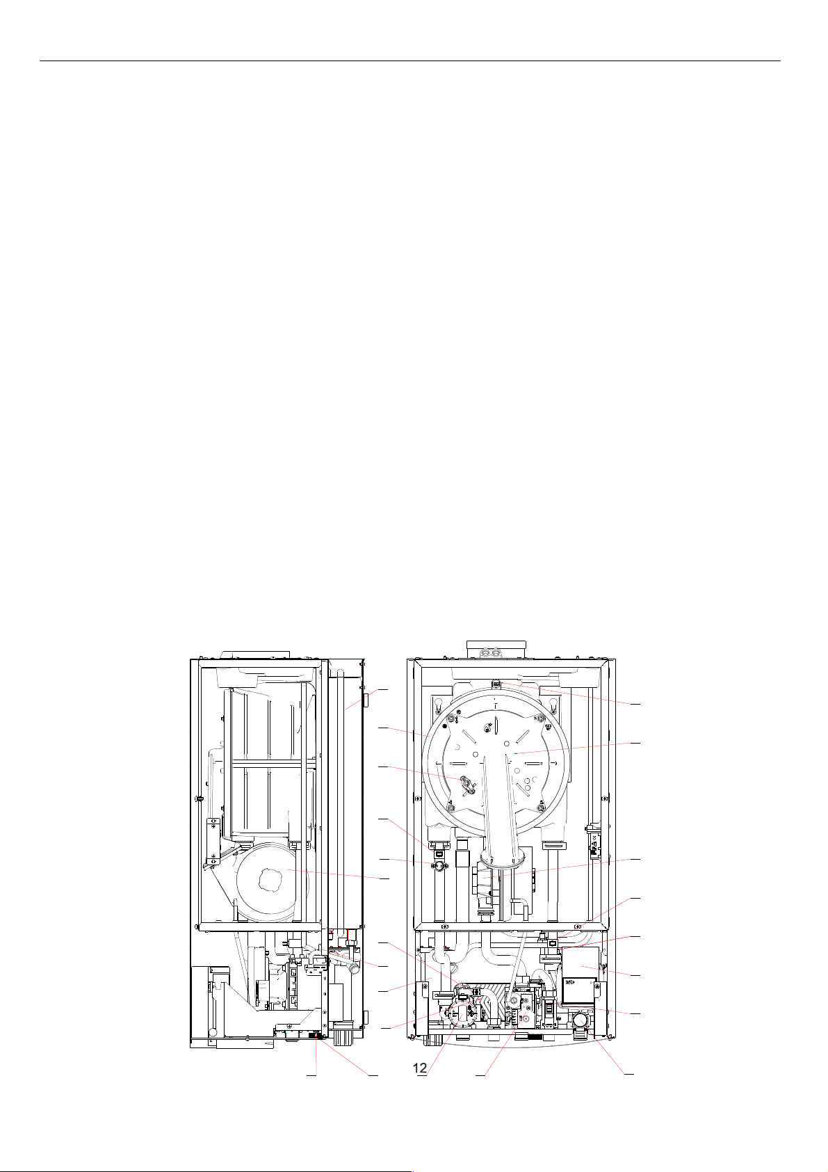
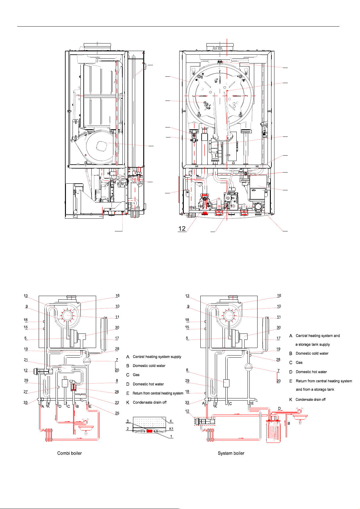
5. Fan,
7. Pump, 19. Heating water pressure transducer,
8. Gas unit 20. Air -vent
10. Flame control/ Ignition
electrode,
22. Filling valve of installation
11. Burner, 25. Safety valve - 3 bar,
12. 3-way valve, 26. Domestic water flow sensor
13. Flue gas-water heat exchanger 27. NTC sensor of domestic water temperature
15. Temperature limiter as a
protection against exceeding the
upper limit water temperature
16. Thermal fuse of flue gas, 30. Mixing unit
17. Expansion vessel 33. Drain valve
18. NTC sensor of heating water -supply
21. Plate water-water heat exchanger,
28. NTC temperature sensor of heating water return (only in boilers with PWM pumps)
29. Siphon
17
16
13
11
10
18
33
Fig.2.2.1.1. Location of elements in combi boiler ECOCONDENS SILVER PLUS
22
15
27
20
29
5
21
30
18
28
19
7
26
8
25
ECOCONDENS SILVER PLUS
Only Fig. 2.2.1.
3.
1.
3
ISU-646:2016/GR-H str.4
17
16
13
11
10
18
15
30
5
28
19
20
7
25
33
29
a
8
Fig.2.2.1.2. Location of elements in system boiler: ECOCONDENS SILVER PLUS
Swich of boiler function selection
2. Temperature selector (c.h. or d.h.w.)
. Heating water, domestic water and static pressure temperature display with error
codes diagnostic
4. Control panel
K1. ON/OFF, reset
Fig.2.2.1.3. Scheme of boiler operation
ECOCONDENS SILVER PLUS
o
3
±
0.02
±
0.2
SB
min
ISU-646:2016/GR-H str.5
2.2.2. Technical data
SYSTEM BOILER: ECOCONDENS SILVER PLUS COMBI BOILER: ECOCONDENS SILVER PLUS
Parameter Unit
-20 -25 -35 -20 -25 -35
Size
E n e r g e t i c p a r a m e t e r s
C e n t r a l h e a t i n g c i r c u i t
Boiler thermal power at 80/60oC (modulated) kW 2.7 ÷ 20.0 3.9 ÷ 24.0 4.1 ÷ 34.7 2.7 ÷ 20.0 3.9 ÷ 24.0 4.1 ÷ 34.7
Boiler thermal power at 50/30oC (modulated) kW 3.0 ÷ 22.0 4.3 ÷ 26.5 4.5 ÷38.2 3.0 ÷ 22.0 4.3 ÷ 26.5 4.5 ÷ 38.2
Heat load kW 2.8 ÷ 20.4 4.0 ÷ 24.6 4.2 ÷ 35.6 2.8 ÷ 20.4 4.0 ÷ 24.6 4.2 ÷ 35.6
The efficiency of the boiler at nominal load
and average boiler water temp. 70 oC
The efficiency of the boiler at partial load and
return water temperature 30 oC
% 97.6 98.0 98.0 97.6 98.0 98.0
% 107.9 108.7 109.0 107.9 108.7 109.0
Modulation range % 13-100 16-100 12-100 13-100 16-100 12-100
Seasonal space heating energy
efficiency
ɳ
s
Seasonal space heating energy efficiency
class
Useful heat output :
- at rated heat output P4
- at 30% of rated heat output P1
Useful efficiency :
-
ɳ
4
ɳ
-
1
Nominal kinetic pressure in front of the boiler
for gas:
2E-G20, 2H-G20
3B/P-G30, 3P-G31
% 91 92 92 91 92 92
A
kW
kW
%
20.0
6.0
88.0
97.0
24.0
7.2
87.9
96.9
34.7
10.4
87.8
96.5
20.0
6.0
88.0
97.0
24.0
7.2
87.9
96.9
Pa (mbar)
2000 (20); 2500 (25); 2000 (20); 1300 (13)
2800 ÷ 3000 (28 ÷ 30); 3000 (30); 3700 (37); 5000 (50)
34.7
10.4
87.8
96.5
Maximum water pressure MPa (bar) 0,3 (3)
Max temperature (central heating)
Standard adjustable temperature
Reduced adjustable temperature
C 95
40 ÷ 80
°C
25 ÷ 55
Lift of the pump at flow 0 kPa (bar) 70 (0,7) 70 (0,7)
D o m e s t i c h o t w a t e r c i r c u i t
Nominal heat output of the boiler
at temp. 80/60oC
kW ----- 2.7 ÷ 25 3.9 ÷ 30.0 4.1 ÷ 40.0
Nominal heat load kW ----- 2.8 ÷ 25.6 4.0 ÷ 30.7 4.2 ÷ 41.0
The efficiency of the boiler at nominal load
and average boiler water temperature of
% ----- 97.6 98.0 98.0
70°C
Water heating energy efficiency class A A A
Load profile L XL XL
Water pressure MPa (bar) -----
0.01 (0.1) ÷ 0.6 (6)
Min water flow l/min ----- 2.0
Max water flow (flow limiter) dm3/min ----- ----- ----- ---Range of water temperature regulation °C 30 - 60
Flow of domestic water for ∆t=30K
dm3/min 12 14 19
E n v i r o n m e n t a l p r o t e c t i o n
Emissions of nitrogen oxides mg/kWh 21 24 29 21 24 29
Emission of NOx (natural gas) class 5
The pH of the condensate
Sound power level L
WA
natural gas - 5
dB
48 48 48 48 48 48
H y d r a u l i c p a r a m e t e r s
Expansion vessel capacity dm
Water pressure in expansion vessel MPa (bar) 0.08
6
(0.8
)
E l e c t r i c p a r a m e t e r s
Type and supply voltage V ~ 230 ±10%/ 50Hz
Degree of protection IP44
Power consumption W 110
Standby mode power consumption P
Electricity consumption :
- at full load el
- at part load el
max
Maximum nominal current value of output
terminals
Controller classification according to PN EN
298
kW 0.005
kW
kW
0.05
0.02
0.05
0.02
0.05
0.02
A 2
F-M-C-L-X-K
0.05
0.02
0.05
0.02
0.05
0.02
Type of flame sensor ionization
T h e p a r a m e t e r s o f f l u e g a s
Fan characteristics section 4.4 of this manual
Flue gas mass flow at full load kg/h 51.4 72.3 90.4 51.4 72.3 90.4
Flue gas mass flow at partial load kg/h 5.4 9.5 9.6 5.4 9.5 9.6
The minimum flue gas temperature at
minimum thermal power
The maximum flue gas temperature at
maximum thermal power
°C
°C
44 34.3 34.3 44 34.3 34.3
61 66.9 66.7 61 66.9 66.7
T i m e p a r a m e t e r s
Time of central heating pump rundown s 180
Time preventing the anti-cyclical startup of
the boiler (Anti-cycling time)
minutes 3-60
Time of domestic hot water pump rundown s 20-180
Protection against pump and valve blocking
h /s the pump turns on for 180 seconds every 24 hours
the pump and three way valve turns on for 15 seconds every 48 hours
ECOCONDENS SILVER PLUS
NOTICE!
It is forbidden to
make any
unauthorized
modifications in the protection system.
ISU-646:2016/GR-H str.6
A s s e m b l y d i m e n s i o n s
Connection to the chimney duct
( section 3.8. and table 7.1.)
mm
Coaxial Φ80/Φ125, Coaxial Φ 60/Φ100 or 2 separate Φ80 x Φ80
Connection of heating water (CH) and gas inch G3/4
Connection of DHW inch G3/4 G1/2
Dimensions mm 785x400x 334 785x400x 334 785x400x 334 785x400x 334 785x400x 334 785x400x 334
Boiler weight kg 31.5 32.5 37.5 33.5 34.5 39.5
The manufacturer reserves the right to make changes in the construction of the boiler, which are not mentioned herein and have no influence on the technical and functional
characteristics of the product.
2.3. Protection equipment
• Protection against gas outflow
• Protection against explosive gas switching on
• Protection against exceeding the max temperature in the heating water system
• Protection against exceeding the upper limit of heating water temperature
• Protection against water pressure increase (1-st degree)- electronic
• Protection against water pressure increase (2-nd degree)- mechanical
• Protection against drop of water pressure
• Protection against water overheating
• Anti-freezing protection of the boiler
• Protection against the pump blockade
• Monitoring of the correct operation of the fan. Fan failure is detected if the current fan speed is different from that
expected by the driver of the boiler.
• Protection against exceeding the upper limit temperature of flue gas (115°C).
Errors which do not require manual reset will cause return of the boiler to the normal operation after automatic disappearance of failure
section 5.8 - boiler diagnostics.
In case of noticing repeated emergency boiler shut-down by any of the protection it is necessary to contact an Authorized
Service Company in order to check the reason of boiler switching off and to repair it.
2.4. Operation description
2
.4.1. Way of heating the water for central heating system
The boiler switches on if the heating water temperature drops about 5 degrees below the set temperature - as described in section 5.5.1 and the room
thermostat gives the signal to heat. Then the following conditions occur simultaneously:
• power supply of the three-way valve (item 12 towards the central heating installation),
• pump supply (item 7),
• fan supply (item 5),
• the sequence of ignition,
• then the driver starts the fan speed regulation so as to obtain the desired temperature of heating water
The boiler switches off when the room temperature control unit is signalizing desired temperature in the room or when heating water temperature is
higher than desired (by value of hysteresis see P20). In this case the “L3” is shown on the display. After switching off the burner, pump runs for about
180 s, and fan for 15 s.
Restart of the boiler will be done automatically under the following conditions simultaneously:
The list of driver parameters according to Table 5.6.
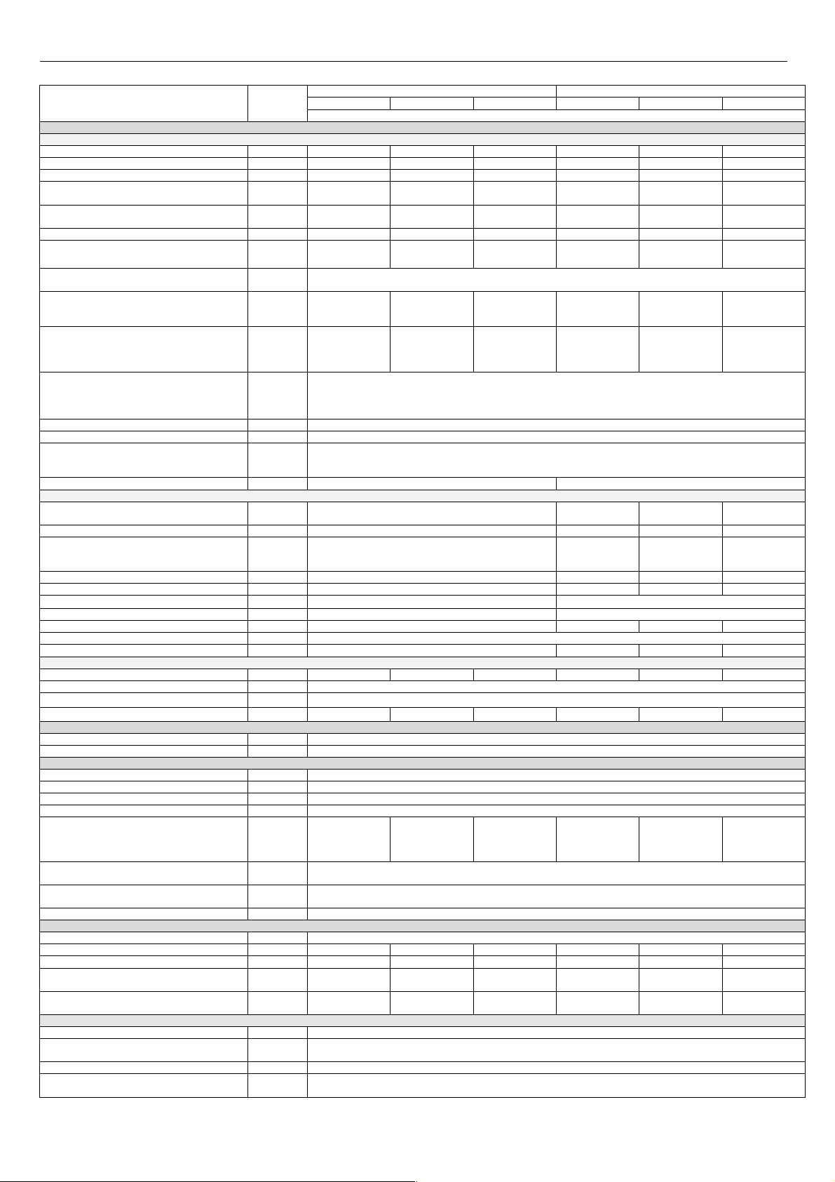
2.4.2. Temperature regulation dependent on external temperature
If an external temperature sensor has been connected the controller detects it automatically and goes to the weather function mode.
Controller adjusts the heating water temperature making it dependent on outside temperature and coefficient of the slope of the heating curve Kt” and
parameter P22 diagram shown on the Fig. 2.4.2.1 and 2.4.2.2
Changing the value of the coefficient Kt is described in Section 5.5.1.1.
Tm ax 85 C
Tm ax 85 C
.
.
o
o
.
.
c
c
a
a
r
r
u
u
t
t
a
a
r
r
e
e
p
p
m
m
e
e
T
T
Tm in 40 C
Tm in 40 C
Fig.2.4.2.1 Diagram of the heating curve (standard heating)
Notice:
1) for value Tout ≥ 25°C and P22=0 designed temp. Tc.h. is always equa l to Tmin.
2) at max. coefficient Kt and P22=0, Tmax is reached when Tout ≤ 10°C.
3) Tmax will not exceed 80°C for standard heating a nd 55°C for floor heating regardless of the value P 22
• heating water temperature is lower by 5°C than the set temperature,
• room temperature control unit provides the signal "HEAT",
• 180 seconds have passed. waiting time determined by parameter P25 have passed (default 3 minutes) if L3 was displayed.
0
T ma x 55 C
T mi n 25 C
K t= 2
0
50 C
0
45 C
K t= 1, P2 2= 10
.
o
.
c
0
a
40 C
r
u
t
a
r
e
p
m
e
T
0
35 C
K t= 1
0
30 C
0
Kt =0
-4 0
Fig.2.4.2.2 Diagram of the heating curve (floor heating)
K t= 3
-3 0 -2 0 -1 0
Kt =4
Tem p e rat ura z e w n ę trzn a
K t=6
80 C
80 C
70 C
70 C
60 C
60 C
50 C
50 C
0
0
0
0
0
0
0
0
0
0
0
0
-40
-40
Kt= 2
Kt= 2
Kt= 1, P22 =10
Kt= 1, P22 =10
Kt= 1
Kt= 1
Kt= 0
Kt= 0
-30 -20 -1 0
-30 -20 -1 0
Kt= 3 Kt= 4
Kt= 3 Kt= 4
Tem pe ratura zewnętrzna
Tem pe ratura zewnętrzna
Kt= 8Kt= 6
Kt= 8Kt= 6
Kt= 10
Kt= 10
+200 +10 + 25
+200 +10 + 25
K t=8
K t=1 0
+ 200 + 10 + 2 5
ECOCONDENS SILVER PLUS
Q [l/min.]
ISU-646:2016/GR-H str.7
4) In case, when weather regulator works in autonomic mode (parameter P26=2), RT input is treated as an input for choice of time of day: DAY (contact
open) NIGHT (contact closed). During NIGHT time, calculated temp. TCH is reduced by the P28 parameter value. Boiler starts heating CH water if the
outdoor temperature is lower than P27 parameter value. Boiler stops heating CH water if the outdoor temperature is higher than P27 parameter value at
least 3 hours.
5) If P26=0, then weather regulator doesn’t work, it is only outdoor temperature measurement.
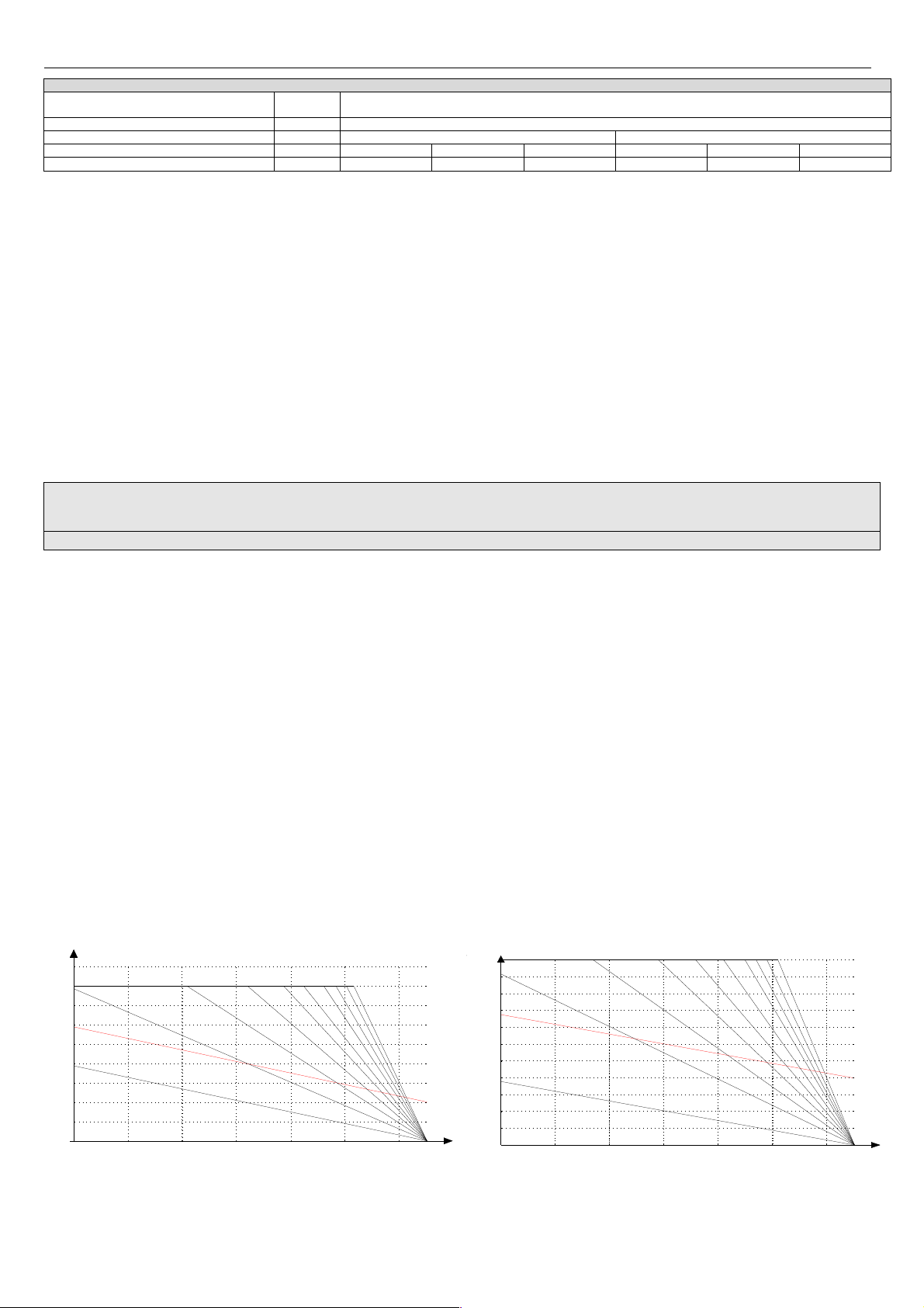
2.4.3. Method of D.H.W. heating in combi boilers
Combi boiler heats the water in a instantaneous way. Water temperature is set using the buttons +/- (p.5.5.2) in the range 30°C to 60°C. The water
temperature at the outlet depends on water temperature at the inlet.
Water flow shall be determined by draw-off valve in the outlet.
In this mode the water heating demand occurs when the flow sensor turns on at the value above 2.0 l /min (ends at a flow < 1.5 l / min.)
Then follows the sequence:
• switching the power of the 3-way valve (item 12) in direction of the water-water heat exchanger supply for the pump (item 7),
• after flame detection and the end of startup sequence, signal from the NTC sensor (DHW) adjusts the fan speed to reach the desired temperature of
domestic hot water item 27
Central heating hot water flows through the water-water heat exchanger segments and heats the water. The heated water is directed to the point of its
collection.
NOTICE: In the case of a lower fan rotation range caused by low water consumption, there is a water temperature increase. Turning off the gas flow to
the main burner will come when the DHW temperature exceeds 65°C.
±10%
60
55
50
45
40
35
30
25
20
15
10
5
0
2 310
Domestic water temperature on the inlet t=15°C
Domestic water temperature on the inlet t=5°C
875 64
181312109 11 171514 16 22212019 23
t max
t min.
Q [l/min.]
. 2.4.3.1. Diagram of domestic water temperature at the boiler
±10%
t [°C]
±10%
t [°C]
60
55
50
45
40
35
30
25
20
15
10
5
0
0 1
432 65 97 8 10
Domestic water temperature on the inlet t=15°C
Domestic water temperature on the inlet t=5°C
11
t max
t min.
1612 13 14 15 1817 19 20 252321 22 24 26 27 28
Fig. 2.4.3.2. Diagram of domestic water temperature at the boiler
outlet at thermal power of 30kW depending on the water flow rate.
60
55
50
45
40
35
30
25
20
15
10
5
0
20 1 3 4 65 7 8
9
t max
t min.
Domestic water temperature on the inlet t=15°C
Domestic water temperature on the inlet t=5°C
28141110 12 13 1615 1817 232119 20 22 2524 2627 373029 3231 353433 36
3938
Q [l/min.]
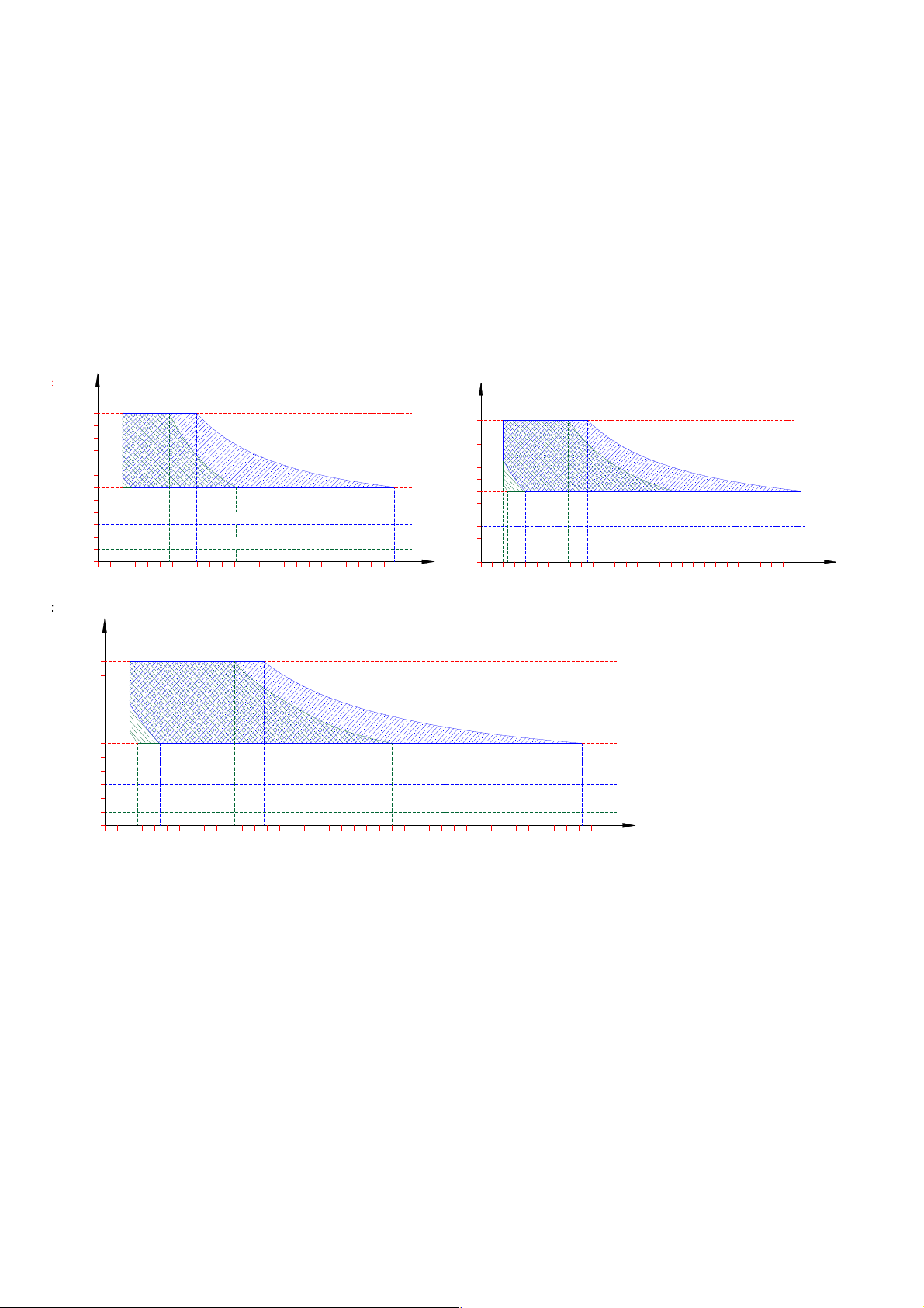
Fig. 2.4.3.3. Diagram of domestic water temperature at the boiler outlet at thermal power of 40kW depending on the water flow rate.
2.4.4. The way of heating the water in system boiler ECOCONDENS SILER PLUS cooperating with domestic water tank.
The boiler may cooperate with domestic water tank type Termet-120, Termet-140 and ZWU200/N. These water tanks are offered by
TERMET company. Adjustment and display of domestic water temperature are done by the control panel of the boiler. Boilers are factory
designed for cooperation with domestic hot water tanks.
The process of heating the domestic water:
When the water temperature sensor detects the temperature lower by 5°C of the set value
(look p.5.5.2)
then the process of pumping the
water to the central heating system will be stopped. Heating the domestic water with the boiler cooperation with the tank of domestic
hot water is as follows:
• water temperature sensor detects the temperature lower by 5°C of the set value (for example as a resu lt of unscrewing the tap);
• boiler controller switches the three-way valve to pump water to a short circuit, while giving a signal to the spark generator and gas
valve item 8;
• heating water with temperature described by parameter P21 (default 75°C) flows through the coil of tan k (short circuit);
• after exceeding by 1°C set water temperature in th e tank the boiler controller switches the 3-way valve for long circuit and after
meeting below mentioned conditions the heating water is pumped into the central heating system:
- heating water temperature is lower by 5°C of the set temperature
- room temperature regulator gives a signal “HEAT”.
The temperature of hot water at the point of consumption may be different from the set value, and therefore it is advisable to
install a mixing valve for domestic hot water systems.
Water heating in the storage tank is active when the electrical bridge is mounted on the TZ input
( Fig.3.9.1.)and when set temperature value is higher or equal to the minimum value. After setting the value lower than the

ECOCONDENS SILVER PLUS
ISU-646:2016/GR-H str.8
minimum, the tank is switched off. This does not apply for frost protection function.
NOTE: To eradicate legionella bacteria in the storage tank, the boiler is turned on every 168h to work with the tank and
heats water to 65°C.
If legionella function does not work in automatic mode, the user at any time can manually initiate a single cycle of tank
heating to 65°C.
2.4.4.1 Manual initiation of disposable tank overheating - Anti-legionella function in manual mode
* (applies to the boilers with tanks):
When the boiler is operating in SUMMER mode:
Press the button twice. After first pressing the button, the display shows (ready to modify) option of CH setting. Next pressing
displays the symbols characteristic of Legionella Function: a flashing key symbol, right field dimmed, in the left field you can see DHW
temperature and the symbol MAX placed above it.
When the boiler is operating in WINTER mode:
Please press the button three times. After first pressing the button, the display shows (ready to modify) option of CH setting. Next
(second) pressing displays the symbols characteristic of Service Function. Next pressing displays the symbols characteristic of
Legionella Function: a flashing key symbol, right field dimmed, in the left field you can see DHW temperature and the symbol MAX
placed above it.
In both modes of operation:
To activate the Legionella Function hold the button ”+” for 2 seconds. After activation Legionella Function the symbol "key" will light up
with solid light. To activate the Legionella you have about 3 seconds. After this time, or when you press the reset button the system
goes to the normal mode characteristic for the selected operation mode.
During the implementation of Legionella Function, the temperature field is dimmed.
Completion of Legionella function is performed automatically or by pressing the reset button or the operation mode change.
2.4.5. Operation of the pump with adjustable speed.
In the boilers equipped with a pump with variable speed (PWM) during the work in DHW mode
- in two-function boilers the pump has maximum speed
- in one-function boilers the speed of the pump is determined by parameter P19
While heating water in C.H. system the controller regulates the pump according to:
For conventional PWM pump operation (parameter P 15 = 0):
PWM Pump (activation by parameter P12) works with a modulated speed in C.H. system activating by signal from RT (room
temperature regulator). The rotational speed is adjusted in such a way that in cooperation with the modulator to achieve the value
of ∆T (defined by parameter P13) between outgoing and return temperature of central heating system. There is maintained a priority to
achieve and hold the set of temperature in central heating system. Minimum allowable rotation speed of the pump is determined by
parameter P14. The maximum allowable rotation speed of the pump is determined by parameter P18
ECO mode (parameter P15 = 1):
PWM Pump (activation by parameter P12) works with a modulated speed in C.H. system activating by signal from RT (room
temperature regulator). The rotational speed is adjusted in such a way that in cooperation with a modulator achieved value ∆T between
outgoing and return temperatures of central heating system calculated on the basis of a preset ratio ECO (p.2.4.5.1). ECO factor is
adjusted on the user interface in the range of 0.1 to 0.9. The default (optimal in most cases) value is 0.5. Selection of lower value
results in lower gas consumption with less heat energy being placed into the room (simplified we decide what part of the radiator has to
be warmed up). The user obtains the possibility of such a regulation of device to get the thermal comfort at minimum cost (less gas
consumption, lower power consumption). The value 0,5 of the coefficient of ECO is the maximum value at which the control regardless
of the temperature setting C.H. water seeks to meet the conditions of condensation (C.H. return temperature <= 55 °C). It is
recommended to work the system at the ECO ratio in the range of 0.1 to 0.5. If increasing the C.H. setting cannot obtain adequate
thermal comfort should gradually increase the value of the ECO. ECO factor equal to 0.9 practically corresponds to the traditional work
of the pump without speed control.
Irrespective of the mode of operation:
Preserved is a priority to achieve and maintain the set temperature C.H. water. Minimum allowable rotation speed of the pump is
determined by parameter P14. The maximum allowable rotation speed of the pump is determined by parameter P18
NOTE:
If the temperature sensor of return central heating water is damaged or is not connected, the pump works with a constant speed.
 Loading...