

TERMET ECOCONDENS CRYSTAL 80, ECOCONDENS CRYSTAL 100 Instruction Manual

INSTRUCTION MANUAL
INSTALLATION, OPERATION
AND MAINTENANCE
Gas-fired condensing
central heating boilers
SYSTEM BOILERS
ECOCONDENS CRYSTAL 80
ECOCONDENS CRYSTAL 100

DEAR CUSTOMER
Congratulations on having chosen ter met product.
We offer you modern, economical and environmentally friendly product, meeting particularly high requirements of European Standards. Please read this instruction
manual carefully as the knowledge of service rules and manufacturer’s recommendations are the conditions of reliable, efficie nt and safe operation of the appliance.
Please keep this instruction manual for the whole operation life of the boiler.
We wish you satisfaction in using our product.
termet
IMPORTANT TIPS
• Read the instruction manual before you perform the installation and operation of the boiler.
• This instruction manual is an integral equipment of the boiler. It should be kept through the whole operation life of the boiler and carefully read. It contains all
the information and warnings for safety during installation, use and maintenance to be followed.
• The boiler is complicated appliance as it contains numerous precise mechanisms.
• Reliable operation of the boiler depends mainly on appropriate performance of systems that boiler cooperates with such as:
- gas system,
- flue gas-air system,
- central heating system,
- domestic hot water system.
• Flue gas - air installation for C type boilers should be made of separately approved and introduced on the market gas - air system. Adapters connecting the
boiler with a pipe system must have a measuring points. Flue gas – air system must meet the specifications set out in section 3.8 of this manual.
• Flue gas - air system must be tight. Leaks on the connections of flue gas pipes can result in flooding of the boiler by condensate. Manufacturer is not liable
for damage and malfunction of the boiler arising out from above mentioned reason.
• Installation of the boiler should be performed only by a qualified person
1)
. Make sure that the installer has confirmed in writing the tightness of the
gas installation had been checked after connecting the boiler to the system.
• Boiler may be installed and operated only in a room where all building works have been completed. It is not allowed to install and operate the boiler in a room
where building works are still in progress.
• The cleanliness of air in a room where the boiler will be installed must meet the same requirements as for rooms designer for people.
• There should be installed appropriate filters on a central heating system and gas system . Filters are not included in a basic boiler equipment.
• An example of connecting a boiler to these systems is presented on fig. 3.5.1.
• All defects caused by lack of filters on central heating or gas supply will not be repaired under guarantee.
• Central heating system must be thoroughly rinsed with water, cleanliness of the heating water should be comparable to cleanliness of domestic water.
• To avoid malicious calcification process of flue gas - water heat exchanger there should be:
- proper tightness of central heating system ensured by avoiding frequent refilling it with water,
- the water hardness checked, if it exceeds 15 On it should be softened by using of softeners available on the market,
- written confirmation of the analysis of water hardness ensured; in the absence of such confirmation any claim under flue gas-water heat exchanger
calcification will not be included under warranty.
• The initial start-up of the boiler as well as its repairs, adjustments and maintenance works must be performed only by AUTHORISED SERVICE COMPANY.
• The boiler must be operated only by an adult.
• Do not do any repairs and modifications by yourself.
• Do not cover any ventilation grilles.
• Do not keep in the vicinity of the boiler any containers with flammable, aggressive and corrosive liquids and other similar substances.
• Any failures that are result of operation discordant to recommendations included in this instruction manual can not be subject to warranty claims.
• Manufacturer is not responsible for any failures being the result of faults during the process of installation and inobservance the regulations and instructions
given by the manufacturer.
• Complying with recommendations given in this instruction manual ensures a long, reliable and safe operation of the boiler.
When you smell gas:
- do not use any electrical switches that could cause any spark,
- open the door and windows,
- shut down the main gas valve,
- contact your gas supplier.
In case of any failure you should:
- disconnect the boiler from a power source,
- shut down the gas supply valve,
- cut off a water supply and drain a water from the boiler and whole central heating system as well (when there is any risk of
freezing of the system),
- drain the water from the system in any case of leakage that could cause a flood ,
- contact the nearest AUTHORISED SERVICE COMPANY or the producer.
1)
‘Qualified person’, means the one that has all required technical qualifications in an area of doing all the works necessary to connect appliances to the gas mains, central heating system and flue
gas duct, accordingly to local regulations.

1. INTRODUCTION ................................................................................................................................................................................................................................................. 1
2. BOILER DESCRIPTION ........................................................................................................................................................................................................................................ 1
2.1. TECHNICAL SPECIFICATION .............................................................................................................................................................................................................................. 1
2.1.1. Technical features ........................................................................................................................................................................................................................ 1
2.2. DESIGN AND TECHNICAL SPECIFICATIONS OF THE BOILER ......................................................................................................................................................................................... 1
2.2.1. Main units of the boiler ................................................................................................................................................................................................................ 1
2.3. PROTECTION EQUIPMENT ................................................................................................................................................................................................................................ 1
2.4. OPERATION DESCRIPTION ................................................................................................................................................................................................................................ 2
2.4.1. Way of heating the water for central heating system .................................................................................................................................................................. 2
2.4.2. Temperature regulation dependent on outside temperature ...................................................................................................................................................... 2
2.4.3. The way of heating the water in the monofunctional boiler cooperating with domestic water tank (option). ........................................................................... 2
2.5 DESCRIPTION OF THE CONTROL PANEL ................................................................................................................................................................................................................. 3
3. BOILER INSTALLATION ....................................................................................................................................................................................................................................... 3
3.1. REQUIREMENTS OF BOILER INSTALLATION ........................................................................................................................................................................................................... 4
3.1.1. The regulations on the water installation, gas and the flue gas system ....................................................................................................................................... 4
3.1.2. Regulations related to the room .................................................................................................................................................................................................. 4
3.1.3. Requirements for electrical installation ....................................................................................................................................................................................... 4
3.2. PRELIMINARY CHECK ACTIVITIES ........................................................................................................................................................................................................................ 4
3.3. BOILER INSTALLATION ..................................................................................................................................................................................................................................... 4
3.4. CONNECTION TO THE GAS INSTALLATION ............................................................................................................................................................................................................. 6
3.5. CONNECTION OF THE BOILER TO A WATER SYSTEM ................................................................................................................................................................................................ 6
3.5.2. Cleaning the installation and water treatment for filling the CH installation ................................................................................................................................ 6
3.6. SELECTION OF EXPANSION VESSEL ...................................................................................................................................................................................................................... 7
3.7. CONDENSATE OUTLET ..................................................................................................................................................................................................................................... 7
3.8. FLUE GAS OUTLET .......................................................................................................................................................................................................................................... 7
3.8.1. Configuration Type B with open chamber and forced draft ......................................................................................................................................................... 7
3.8.3. Maximum length of the air-flue system........................................................................................................................................................................................ 8
3.8.4. Horizontal outlet of air- flue gas system through the wall ............................................................................................................................................................ 8
3.8.5. Vertical outlet of air- flue gas system through the roof ................................................................................................................................................................ 8
3.8.6. Connection to the existing flue gas duct....................................................................................................................................................................................... 8
3.9. CONNECTION OF ADDITIONAL DEVICES ............................................................................................................................................................................................................... 8
3.9.1. Description of connection terminals ............................................................................................................................................................................................ 9
3.9.2. Connection of a room temperature regulator .............................................................................................................................................................................. 9
3.9.3. Connecting the outdoor temperature sensor ............................................................................................................................................................................... 9
3.9.4. Connecting the hot water tank to the system boiler .................................................................................................................................................................... 9
3.9.5. Connecting the solar system ...................................................................................................................................................................................................... 10
3.9.6. Connecting the boilers in the cascade system ............................................................................................................................................................................ 10
4. BOILER ADJUSTMENT AND PRELIMINARY SETTING ........................................................................................................................................................................................ 10
4.1. INTRODUCTORY REMARKS.............................................................................................................................................................................................................................. 10
4.2. ADJUSTING THE BOILER TO COMBUST ANOTHER TYPE OF GAS ................................................................................................................................................................................. 11
BOILER CAN BE ADJUSTED TO COMBUST ANOTHER TYPE OF GAS BUT ONLY FOR THIS ONE WHICH THE BOILER IS CERTIFIED FOR. THE TYPES OF GASES ARE GIVEN ON THE RATING PLATE - IN THE INDEX
DESIGNATION: ................................................................................................................................................................................................................................................... 11
4.3. Boiler setting – regulation of CO2 value ......................................................................................................................................................................................... 11
4.4. ADJUSTMENT OF HEATING AND DOMESTIC WATER POWER .................................................................................................................................................................................... 12
4.5. CONTROLLER CONFIGURATION – SETTING OF BOILER PARAMETERS ......................................................................................................................................................................... 12
4.5.1. Preview of parameters value. ..................................................................................................................................................................................................... 12
5. STARTUP AND OPERATION OF THE BOILER ..................................................................................................................................................................................................... 13
5.1. INITIAL STARTUP OF THE BOILER ...................................................................................................................................................................................................................... 13
5.2. OPERATING MODES...................................................................................................................................................................................................................................... 13
5.3. SETTINGS ................................................................................................................................................................................................................................................... 14
5.3.1. Change the setting of heating water .......................................................................................................................................................................................... 14
5.3.2. Change the setting of domestic water ........................................................................................................................................................................................ 14
5.3.3. Switching the SUMMER / WINTER mode .................................................................................................................................................................................... 14
5.3.4. Turn off the heating of domestic water ...................................................................................................................................................................................... 14
5.3.5. Stand-by mode ........................................................................................................................................................................................................................... 14
5.4. DIAGNOSIS ................................................................................................................................................................................................................................................. 14
5.4.1. Errors history .............................................................................................................................................................................................................................. 15
5.5. ANTIFREEZE FUNCTION ................................................................................................................................................................................................................................. 15
5.6. FUNCTION TO PREVENT BLOCKAGE OF PUMP AND THREE-WAY VALVE ...................................................................................................................................................................... 15
5.7. BREAK IN OPERATION OF THE BOILER ................................................................................................................................................................................................................ 15
6. MAINTENANCE, INSPECTIONS, CHECKING OF THE OPERATION ...................................................................................................................................................................... 16
6.1. INSPECTION AND MAINTENANCE ..................................................................................................................................................................................................................... 16
6.1.1. Preparing the boiler for service .................................................................................................................................................................................................. 16
6.1.2. Maintenance of the combustion chamber, burner, ignition electrode and ionization electrode ............................................................................................... 16
6.1.3. Thermal protection of the heat exchanger ................................................................................................................................................................................. 17
6.1.4. Cleaning the condensate siphon................................................................................................................................................................................................. 17
6.2. REPLACING A DAMAGED CONTROL BOARD IN THE CONTROL PANEL.......................................................................................................................................................................... 17
6.2.1. Replacing the fuse in the controller ............................................................................................................................................................................................ 17
6.3. THE MAINTENANCE OPERATIONS TO BE PERFORMED BY USER ................................................................................................................................................................................ 18
6.4. PUMP CHARACTERISTIC ................................................................................................................................................................................................................................. 18
6.5. PARAMETERS OF BOILER COMPONENTS ............................................................................................................................................................................................................ 19
7. CASCADE SYSTEM ............................................................................................................................................................................................................................................ 20
7.1. AUTODETECTION ......................................................................................................................................................................................................................................... 20
7.2. CASCADE OPERATION MODE .......................................................................................................................................................................................................................... 20
7.2.1. TEST mode for cascade ............................................................................................................................................................................................................... 20
7.2.2. Cascade operation in CH mode .................................................................................................................................................................................................. 20
7.2.3. Cascade operation in DHW mode ............................................................................................................................................................................................... 20
7.3. ALGORITHM OF CASCADE OPERATION ............................................................................................................................................................................................................... 21
TECHNICAL DATA ................................................................................................................................................................................................................................................ 22
ISU-689:2016/GB
1
1. INTRODUCTION
In this instruction manual is described condensing gas system boiler
ECOCONDENS CRYSTAL designed for supplying a central heating
system and heating domestic water in separately connected a
domestic water tank.
Adaptation of the following boiler to work with the tank
needs to be made by AUTHORISED SERVICE COMPANY.
ECOCONDENS CRYSTAL boiler take the air for combustion process
from outside the room (in which combustion circuit is sealed) with
respect to the residential area of the building in which it is installed type of installation: C13, C33, C43, C63 or take the air for combustion
process from the room that meets appropriate conditions (required
by law) - type of installation: B23 .
Further information regarding the type – according section 3.8 or PNEN 15502 Standard.
2. BOILER DESCRIPTION
2.1. Technical specification
2.1.1. Technical features
• Electronic fluent flame modulation for central heating system and
domestic hot water (option);
• Electronic ignition with ionization flame control;
• Adjustable boiler power;
• Regulation of heating water and domestic water temperature
(option);
• Function of soft ignition;
• Inlet gas pressure stabilization;
• Adopted to cooperate with closed circuit in central heating system
• Integrated boiler cascade operation
2.2. Design and technical specifications of the boiler
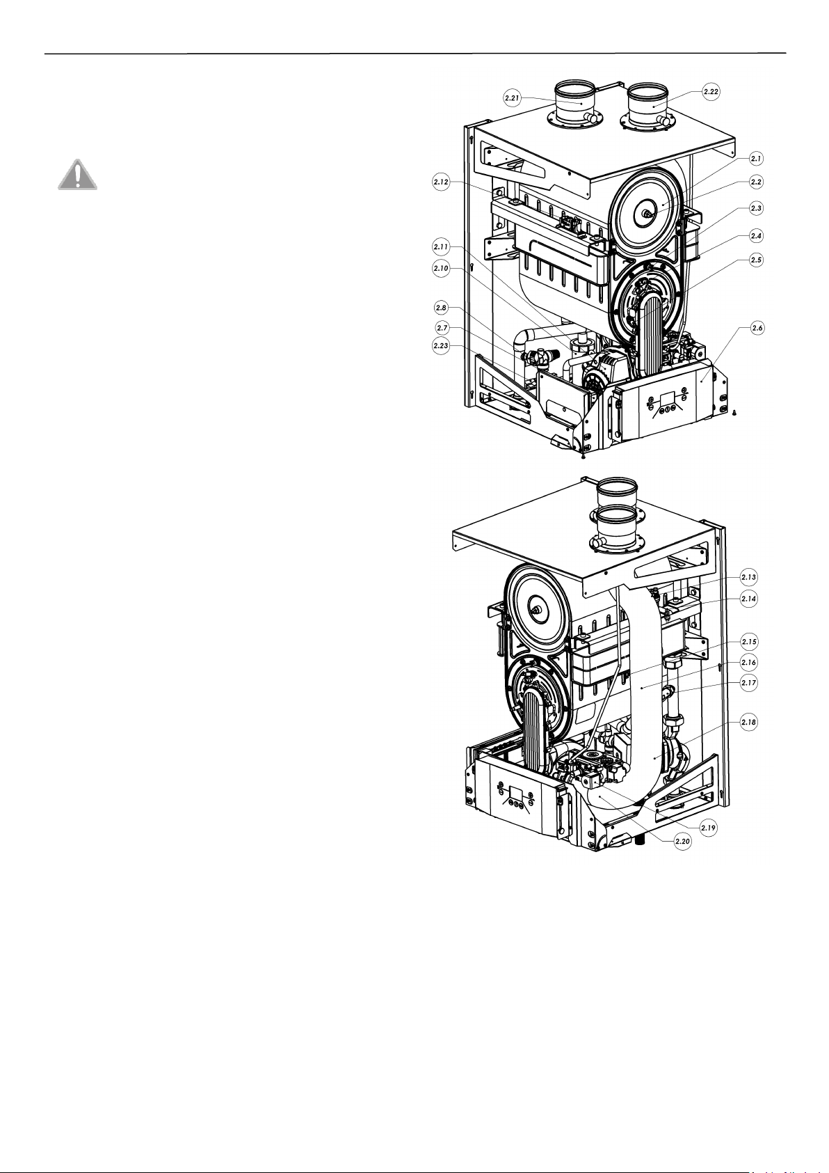
2.2.1. Main units of the boiler
2.1 – Flue gas-water heat exchanger
2.2 – Temperature limiter of flue gas
2.3 – Temperature limiter of air collector
2.4 – Ignitron electrode
2.5 – Flame control electrode
2.6 – Control console
2.7 – Controller
2.8 – Pressure transducer
2.9 – Safety valve
2.10 – Condensate siphon
2.11 – Fan
2.12 – Spark generator
2.13 – Automatic air vent
2.14 – NTC temperature sensor - return
2.15 – NTC temperature sensor - supply
2.16 – Temperature limiter 95°C
2.17 – Flow sensor
2.18 – Circulation pump PWM
2.19 – Gas valve
2.20 – Mixing orifice
2.21 – Flue gas adapter DN100
2.22 – Air adapter DN100
2.23 – Drain valve
2.3. Protection equipment
• Protection against outflow of gas
• Protection against explosive switch on of the gas
• Protection against exceeding the max temperature in domestic
hot water tank
• Protection against exceeding the upper limit of heating water
temperature
• Protection against water pressure increase (1-st degree) -
electronic
• Protection against water pressure increase (2-nd degree) -
mechanical
• Protection against drop of water pressure
• Protection against water overheating
• Antifreeze protection of the boiler
• Protection against the pump blockade
• Monitoring of the correct operation of the fan
• Protection against exceeding the upper limit temperature of flue
gas
• Protection against too small flow through the heat exchanger
• Protection against overheating the exchanger due to incorrect
installation
Fig. 2.2.1.1 – Boiler's construction
ISU-689:2016/GB
2
Errors which do not require manual reset will cause return of the
boiler to the normal operation after automatic disappearance of
failure - see section 5.4 - boiler diagnostics.
In case of noticing repeated emergency boiler shutdown by any of the protection it is necessary to contact
an Authorized Service Company in order to check the
reason of boiler switching off and to repair it.
It is forbidden to make any unauthorized modifications
in the protection system.
IT IS RECOMMENDED TO CARRY OUT A CONTROL BY
AUTHORIZED SERVICE PROVIDED AT LEAST ONCE PER
YEAR. REPLACEMENT OF COMPONENTS IS ALLOWED
ONLY ON ORIGINAL SPARE PARTS.
• HYDRAULIC COUPLING
In order to ensure a proper operation of the boiler, without any
problems of too small flows (e.g. caused by radiators off or various
types of pollution), it is recommended to install a hydraulic coupling
or alternatively a plate heat exchanger that separates the boiler's
hydraulic circuit from the installation.
The choice of separation method is dictated by the type of
installation only.
• PLATE EXCHANGER
In case of replacing a traditional boiler, and an old and contaminated
system, you may encounter problems with thorough cleaning of the
system. In order to avoid contamination of the internal boiler system
and, as a result of its malfunctioning, it is recommended to install an
indirect heat exchanger. An additional exchanger between the
primary and secondary circuits ensures effective separation of the
system and, as a consequence, full protection of the boiler against
contamination.
2.4. Operation description
2.4.1. Way of heating the water for central heating system
The boiler switches on if the heating water temperature is lower than
the temperature set by buttons [E] or [D] and the room thermostat
gives the signal to heat. Then the following conditions occur
simultaneously:
• power supply of the three-way valve towards the central heating
installation,
• power supply of the pump (item. 2.18). If the heating water flow
through the boiler is ≥ 19 l/min, a short-circuit of flow sensor
contacts occurs (item. 2.17),
• power supply of the fan (item 2.11),
• followed by a sequence of ignition and the fan speed is set to
ignition value [parameter P33],
• then the boiler reduces the power by changing the fan speed to the
minimum value [Parameter P12] and maintains it until the
minimum operating time [Parameter P05] has expired. After that
the controller starts the fan speed regulation taking into account a
value of the central heating slope [parameter P06]. If the heating
water temperature exceeds 97°C, an additional temperature limiter
is activated, the burner is turned off until the hot water
temperature drops below 81°C.
The system of continuous flame modulation uses the PI control
algorithm to minimize the difference between the temperature read
by the NTC sensor - supply (item 2.15) and the value of the set
temperature of central heating. The boiler switches off when the
room temperature control unit is signalizing reaching the desired
temperature in the room or when the heating water temperature
exceeds the setpoint by the hysteresis value of central heating
[parameter P03].
After turning off the boiler pump is running during the pump overrun
[parameter P07]. Simultaneously the time of break in operation is
metered [parameter P04].
Restart of the boiler will be done automatically under the following
conditions simultaneously:
• heating water temperature is lower than the set temperature,
• break time in the central heating operation has elapsed [parameter
P04],
• room temperature control unit provides the signal "heat".
The list of driver parameters according to table 4.5.1.
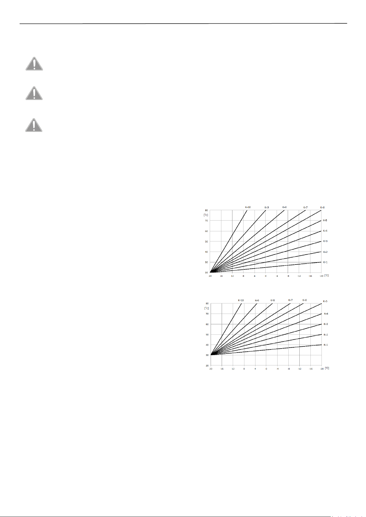
2.4.2. Temperature regulation dependent on outside
temperature
If an external temperature sensor has been connected the controller
detects it automatically and it is signalized by displaying W10 on the
control console display.
If the “K number” (parameter P14) is set to the value different than
zero there is a possibility to manually set the CH temperature with
buttons on control console. Controller enters a weather function and
adjusts the heating water temperature making it dependent on
outside temperature, the number of heating curve [parameter P14]
and its shift [parameter P15]. Max temperature is limited by max CH
setting [parameter P02].
Calculated temperature
of CH water
Outside temperature
Heating curve shift = 20°C
Calculated temperature
of CH water
Outside temperature
Heating curve shift = 30°C
2.4.3. The way of heating the water in the monofunctional
boiler cooperating with domestic water tank (option).
The boiler may cooperate with domestic water tank type ZWU-200/N
which is offered by Termet company. Adjustment and display of
domestic water temperature are done on the controller of the boiler.
Adjusting the boiler to cooperate with the tank see section 3.9.4.
The process of heating the domestic water is as follows:
When the water temperature sensor finds the temperature lower by
the hysteresis value of domestic water [parameter P18] than set on
the control panel with buttons [G] or [F] then the process of
pumping the water to the central heating system will be stopped and
the heating water temperature will be controlled in an optimal way
ISU-689:2016/GB
3
by the driver of the boiler. Heating the domestic water with the
boiler cooperation with the tank of domestic water is as follows:
• water temperature sensor in the tank indicates the water
temperature drop below the set temperature by the hysteresis
value of domestic water [parameter P18] (e.g. due to opening of
inlet tap valve);
• boiler control unit makes the three-way valve to draw the heating
water to a short circuit while giving a signal to the spark generator
and gas valve;
• heating water flows through the coil of tank (short circuit);
• driver of the boiler controls the heating water temperature in an
optimal way so as not to exceed a permissible value. If the heating
water temperature exceeds 97°C, an additional temperature limiter
is activated (item 2.16), the burner is turned off until the hot water
temperature drops below 81°C;
• after exceeding the set water temperature in the tank the boiler
controller gets distorted the three-way valve for long circuit and at
fulfillment of the following conditions the heating water is pumped
into the central heating system:
- heating water temperature is lower than the set temperature
- room thermostat gives a signal “heat”.
Hot water temperature at the point of consumption may differ from
the set value, and therefore it is advisable to install a mixing valve for
domestic hot water systems.
When using a water tank in the ECOCONDENS CRYSTAL
100 boiler , to ensure proper operation of the boiler the
required coil power in the tank is minimum 25kW.
To eradicate legionella bacteria in the tray, the boiler is
turned on every 168h to work with the tank and heats
water to 60°C. To prevent excessive energy
consumption, the timing function is reset when the
water temperature in tank will reach 60°C during
normal use.
2.5 Description of the control panel
The boiler control panel has 7 function buttons and an LCD display
for displaying boiler settings and information about operating states
of the boiler.
Fig. 2.5.1 – Description of control panel buttons
Description of the basic functions of the individual buttons of the
controller:
[A] – Changes the operating state of the boiler from the SUMMER
function (CH only) to the WINTER function (CH and DHW).
[A]
3sec
– The entrance to the TEST mode
[B] – The reset the displayed error
[B]
3sec
– Preview of the parameters
[C] – Turns on or off the DHW heating function
[C]
3sec
– Errors history
[D] – Reduces the setting for CH
[D]
3sec
– Autodetection procedure
[E] – Increases the setting for CH
[E]
3sec
– sends parameters from the controller in MASTER boiler to all
boilers connected in series.
[F] – Reduces the setting for DHW
[G] – Increases setting for DHW
[A+C]
3sec
– Standby mode
[A+B]
3sec
– Test for the cascade mode
[B+C]
3sec
– Controller programming mode
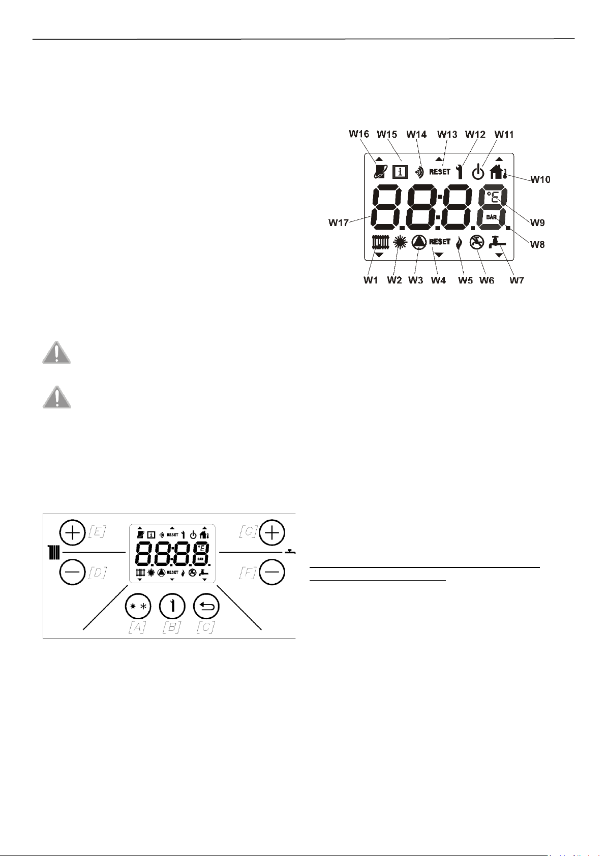
Fig. 2.5.2 – Description of the display symbols
W1 – Operation in CH mode
W2 – Function of operation only in DHW mode (SUMMER), CH
inactive
W3 – Signalization of the pump power
W4 – Signalization the fault requiring reset
W5 – Signalization of the flame presence
W6 – Inactive domestic water function
W7 – Operation in DHW mode
W8 – Unit of displayed pressure
W9 – Unit of displayed temperature
W10 – Active outdoor temperature sensor
W11 – Standby mode
W12 – Signalization the mode of changing the parameters
W13 – Inactive
W14 – Inactive
W15 – Signalization the mode of previewing the parameter
W16 – Presence of connected OpenTherm
W17 – Information display field
3. BOILER INSTALLATION
Important safety information
FAUILER TO COMPLY WITH LISTED RECOMMENDATION WILL
RESULT IN LOSS OF THE WARRANTY
- The boiler must be installed by an authorized service company
accordingly with local regulations;
- After the boiler installation check the tightness of all connections of
gas and water systems;
- Service company is responsible for the proper installation of the
boiler;
- Installation of the boiler must be made so as not to cause any
tension of the installation that may cause increased volume of work;
- Packages should not be left within reach of children;
- Check whether the chimney is perfectly clean and free of dirt;
- The boiler must be connected to the heating system corresponding
to its power;
- Check whether the boiler is adapted to burn a certain type of gas;
- Check the water hardness, if it exceeds 20 F (1F = 10 mg calcium
carbonate per liter of water) proceed to the water softening;
- It is mandatory to thoroughly clean all installation wires in order to
eliminate possible residues from threading, welding, solvents or
sludge and any other contaminants from the heating circuit.
ISU-689:2016/GB
4
3.1. Requirements of boiler installation
3.1.1. The regulations on the water installation, gas and the
flue gas system
Water, gas and flue gas systems must meet local regulations as well
as use of the gas, ventilation and flue gas installation.
The use of gas appliances, flues and ventilation by the user should be
consistent with local requirements on technical conditions of tenant
buildings use.
Before installing the boiler the consent from the District Department
of Gas, Chimney sweep company and Building administration must
be obtained.
3.1.2. Regulations related to the room
Requirements for premises where gas appliances are installed shall
be in accordance with local regulations. The room where appliance is
to be installed should ensure the air supply and venting system
necessary for gas combustion in accordance with local regulations.
The room should be protected against freezing, free from dust and
aggressive gases. It is forbidden to install the device in a laundry
rooms, drying rooms and in varnish, cleaners, solvents and sprays
storages.
The boiler should be installed in a technical room.
Gas appliances supplied with liquefied gas must not be
installed in room with a floor below ground level.
3.1.3. Requirements for electrical installation
The boiler has been designed for operation with single-phase
alternating current with rated voltage of 230 V / 50 Hz. Max power
consumption – please see rating plate or technical data table. The
main socket from which boiler is powered must meet the local
requirements.
The boiler has been designed as a Class I device and must be
connected to an electrical outlet with ground terminal in accordance
with PN IEC 60364-4-41. The boiler has a degree of electrical
protection provided by the housing – X4D.
It should be checked by a suitably qualified person whether the
electrical installation is suitable for the maximum power
consumption of the device, making sure in particular that the crosssection of the cables is suitable for the power consumed by the
device.
If the boiler is permanently connected to the power source, it should
be execute by junction box. The junction box must be equipped with
protection degree appropriate for the defined assembly zone. If the
boiler is connected through the junction box, electric system must be
equipped with measures which can disconnecting the boiler from the
power source.
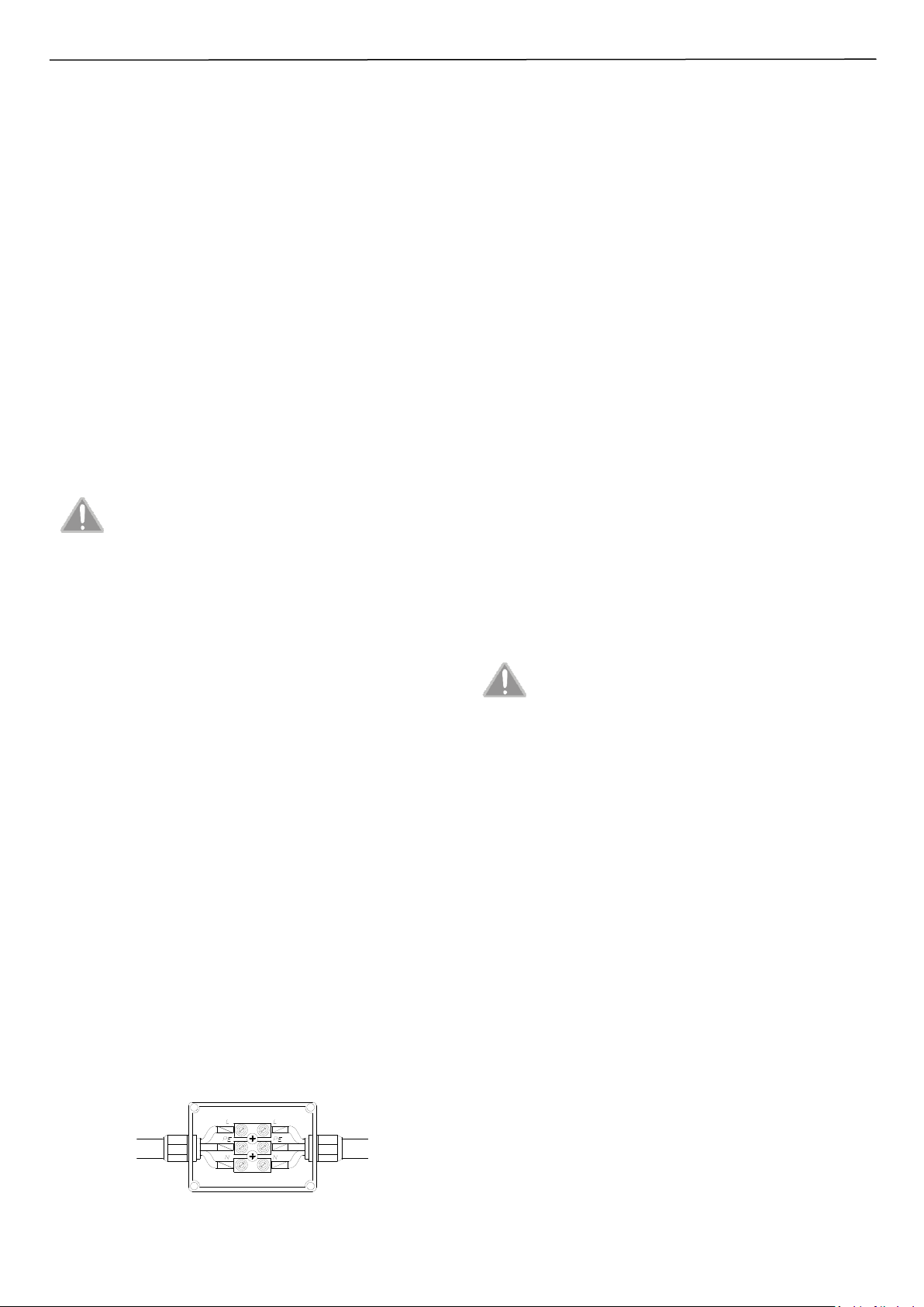
In order to connect the boiler to the junction box, it is recommended
to:
- cut the power cord to a suitable length for connection to the box
- pull off cable insulation
- put the cable-end sleeve with the appropriate diameter
This prepared cables connect according to Fig 3.1.3.1.
Fig 3.1.3.1 – Wire colors: L – brown; N – blue; PE – yellow-green
If you need to replace the supply wire, use a minimum cord of 3 x
0.75 mm2. The boiler supply wire is screwed to the connection list on
the control panel to terminals marked with ~ 230 V (see section
3.9.1).
The power cord of the device cannot be replaced by the user. To
replace it please contact with qualified personnel.
The use of any device powered by electricity requires to compliance
with the basic principles, i.e.:
• do not touch the device with wet or damp body parts and / or
being barefoot;
• do not jerk the electrical cables;
• do not expose the device to weather conditions (rain, sun, etc.);
• do not allow children or persons with no experience or knowledge
to operate the device.
3.2. Preliminary check activities
Before proceeding with the boiler installation:
• check whether the boiler is factory designed for the type of gas
supplied from the gas system. The type of gas which the boiler is
adjusted to is specified on the rating plate on the cover of the
boiler;
• check whether the water system and radiators have been rinsed
with water in order to remove rust, fillings scale, sand and other
dusts that could disturb the proper operation of the boiler (for
example increase the water flow resistance in central heating
system) or to pollute the heat exchanger,
• whether the mains voltage has a value of 230V and the phase wire
(L) is in the right place; and that the socket has an efficient safety
contact (complies with IEC-60 364-6-61: 2000)
• whether the flue-gas air installation is tightly connected and not
obstructed.
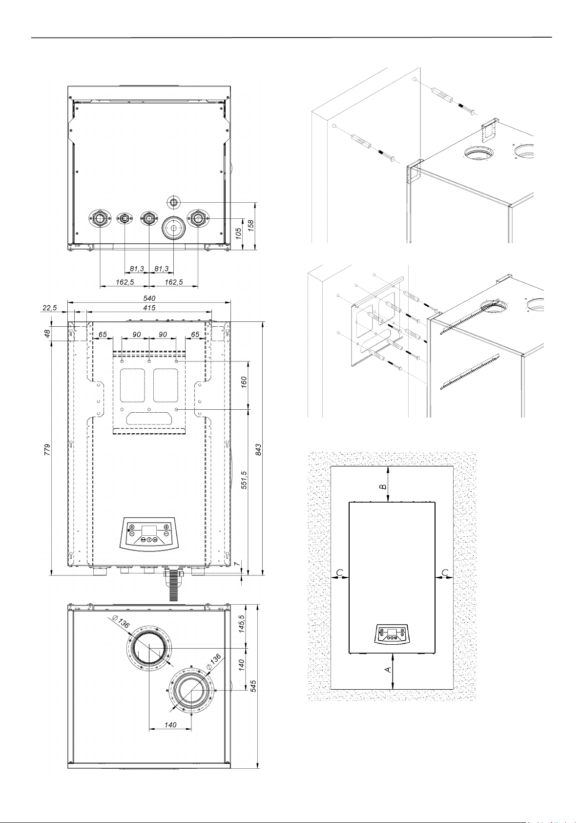
3.3. Boiler installation
The device may only be installed on a vertical wall
sufficiently strong to maintain its weight. For mounting,
use a fastening system adapted to the wall structure.
- The most important mounting dimensions are shown on Fig. 3.3.1
- In order to ensure free access during inspections and maintenance,
it is advisable to maintain the minimum distances according to
Fig. 3.3.3.
Delivery range:
Part
Quantity
Gas boiler
1
Instruction manual
1
Mounting template
1
Hanger
1
Wall plugs Φ12x60
6
Wood screws Φ8x70
6
Elements of the siphon
(bucket, nut, gasket)
1
Flue gas / air adapter
2
Package with screws
Wire of cascade serial connection
1
1
NTC temperature sensor (cascade)
1
The boiler has two mounting possibilities presented on Fig. 3.3.2
- Using the attached hanger
- Hanging on mounting hooks (min. size of wall plug is ø16x100)
Mounting method:
1. In order to facilitate assembly, use the mounting template
attached to the boiler.
2. Attach the template to the wall and mark all the space needed for
installation.
3. Remove the template and drill the necessary mounting holes.
4. Screw the hanger (attached to the boiler) to the wall or mount the
hooks.
Power wire
the device
Wire of
electric
system
ISU-689:2016/GB
5
5. Hang the boiler on the hanger, grabbing the back and bottom of
the boiler. Due to the heavy weight, 2 people are required.
Fig. 3.3.1 – Mounting dimensions
Mounting method on hooks
Mounting method with hanger
Fig. 3.3.2 – Mounting method
Fig. 3.3.3 – Required mounting distances
A = 400mm
B = 300mm
C = 200mm
ISU-689:2016/GB
6
3.4. Connection to the gas installation
All connections should be made by an appropriately
qualified person, in accordance with applicable standards
and regulations, in particular those relating to safety.
Connect a gas supply pipe directly to the connector of the boiler gas
unit by means of standard connector subassembly. It is necessary to
install a gas filter on the gas supply pipe. This filter is not included in
the standard boiler equipment. The gas filter is necessary for a
proper operation of a gas unit and a burner. Install a cut-off valve on
the gas pipe in an accessible place.
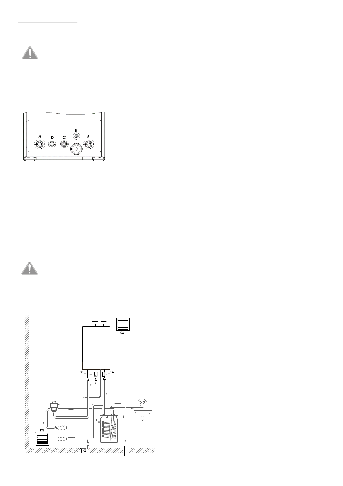
A - (G5/4”) – Power supply of the CH
installation
B – (G5/4”) – return from the CH
installation
C – (G1”) – Gas connection
D – (G3/4”) - Drain from the safety
valve / emptying the boiler
E – (Ø 25) - Condensate drain
Fig. 3.4.1 – Description of the connectors
3.5. Connection of the boiler to a water system
Power connector and connector of return of the central heating
boiler should be screwed to the installation. Install a water filter on a
water return from central heating system (in front of the connection
with the pump). The filter is not included in standard boiler
equipment. The central heating system should be thoroughly rinsed
out before the boiler is connected. In the central heating system it is
permitted to use as a heat carrier any antifreeze fluids which can be
used in central heating systems.
The cut-off valves needs to be installed between the boiler and
central heating system so that the boiler could be dismounted
without draining the system.
Before installing the boiler thoroughly flush the central
heating system to free it from any solid impurities.
It is recommended that after first start-up of the boiler
and heating up of the installation drain the water from
the system to remove residues of pastes metallurgical
and precautionary measures of heaters. These activities
would benefit for the operation of the device, its
parameters and components life.
Fig. 3.5.1 – Installation requirements
KW – Exhaust ventilation, KN – Air inlet, 3W – three-way valve, TS – Tank temp.
sensor, KS – Floor drain, FW – Water filter, FS – gas filter.
After the boiler installation it is necessary to:
• Fill the heating system with water. Filling the system should be
done slowly to allow the air outflow through the air vent valve
mounted in the boiler; also check the complete air outlet from all
components of the system. The pressure in the cold installation
should be 1.2 ÷ 1.5 bar.
• Check whether connections of the boiler and in the central heating
system are tight.
• Ensure that pipes of water and heating installation are not used as
grounding the electrical installation.
• Connect the outlet of safety valves to the floor drain to avoid
flooding the room (where the boiler is installed) as a result of
protection devices. Such outlets should be carried out so as to
avoid damage in the case of opening of the valve and outflowing of
the hot fluid.
3.5.2. Cleaning the installation and water treatment for
filling the CH installation
In all elements of the CH installation there are processes of scaling,
corrosion and similar phenomena. The boiler is the most expensive
part of the installation and it is important to ensure that the heat
exchanger and other components are protected against these
processes. Correct preparation of the CH system for the operation
shall be carried out by two operation: cleaning the installation and
water treatment for the operation of the installation.
Cleaning the installation
In new installation there may be remnants of the installation such as
solder residues, welding residues, flux residues, oil residues, grease
residues, or corrosion products - especially in old installation. In the
first place, both new and old installations should be cleaned with
clean water to remove solid waste. his operation must be carried out
without the boiler installed. The next step is to chemical cleaning the
installation. For cleaning new and old installations, use a suitable
cleaning agent, like Fernox Cleaner F3 (for old and heavily
contaminated installations use Cleaner F5). After this cleaning the
system should be rinsed with mains water.
Water treatment for filling the installation
Use the water with following parameters to fill the installation: pH
from 6,5 to 8,5 units, general hardness not more than 10 °n (~ 18°F).
For filling do not use demineralized water or distilled water. For
proper protection against scale and corrosion of the installation, use
a suitable inhibitor (passivator) e.g. Fernox Protector F1. In addition,
there can also be used a liquid heat carrier such as HP-5 or antifreeze
such as Fernox Alphi 11. In situations where water is very hard, the
use of the HP-5 liquid heat carrier effectively reduces the risk of
scaling of the heat exchanger.
Low-temperature circuits
In low-temperature zones it is recommended to treat the water by
using HP-5 liquid heat carrier or alternatively Fernox biocide AF10.
Filtering technology
In addition, modern filters with magnetic and cyclone effects are
recommended for the high quality of the current heating system.
The method and amount of use of the particular products for
cleaning the installation and for water treatment should be used
according to the instructions of the product given by the
manufacturer.
Cleaning the installation and water treatment should be made by
authorized installers or service personnel.
 Loading...