

MULTI FRIENDLY Air Conditioning Systems
Convertible type Indoor Units:
HSFL 411 XMR
HSFL 531 XMR
HCNL 821 XMR
Outdoor Unit:
SERVICE MANUAL

-2-
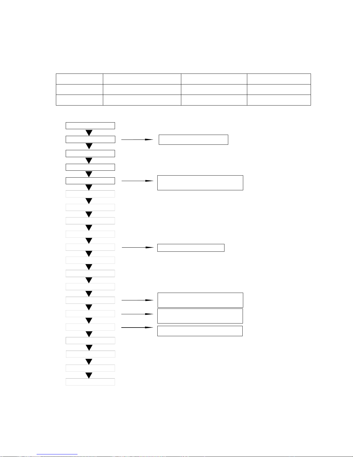
1. Description of products & features
1.1 Brief Introduction for T1 working condition
1.2 Operating Range of Air Conditioners
Working temperature range
Rated Maximum Minimum
Indoor
DB℃
27 32 18
WB℃
19 23 14
outdoor
DB℃
35 43 10
Cooling
WB℃
24 26 6
Indoor
DB℃
20 27 15
WB℃
14.5 -- --
outdoor
DB℃
7 24 -15
Heating
WB℃
6 18 --
Climate type
T
ype of
Air Conditioner
Cooling Only 18 ℃~43℃
Heat pump -7℃~43℃
Electricity Heating ~43℃
T1
-3-
1.3 Product features
Highly efficient, can match with the universal outdoor unit
The outdoor unit can match with cassette, wall mounted type, duct, console and ceiling floor type
indoor unit. One set outdoor can match with multiple indoor units, up to 4 sets. Even when you
have already installed the air conditioner, if you want to add or reduce one unit, go ahead freely as
long as your operation complies with our design. Greatly convenient for designer and installer.
Total indoor load can be up to 135% than the standard match
The total capacity of all indoor units can be 135% more than the nominal cooling capacity, but the
total indoor cooling capacity will not be increased.
Adopt the much friendlier refrigerant R410A
The air conditioner system adopts the greatly friendly refrigerant R410A, which is protective for the
ozone layer and is good to avoid the earth getting warmer. Benefit for the environment.
Adopt the advanced DC inverter technology
The system adopts the advanced DC inverter technology, which can consume less power energy to
realize the equal efficiency, saving money for you.
With air inlet filter, enhance the air quality
The high efficiency filter can collect the dirt and remove the bacterium, which can be installed on the
easy-to-unload place, convenient to be cleaned.
Convenient infrared remote controller
This remote controller YR-H71 can realize the oprional healthy air flow and sterilize function, it is
mobile type appearance, so smart and compact.
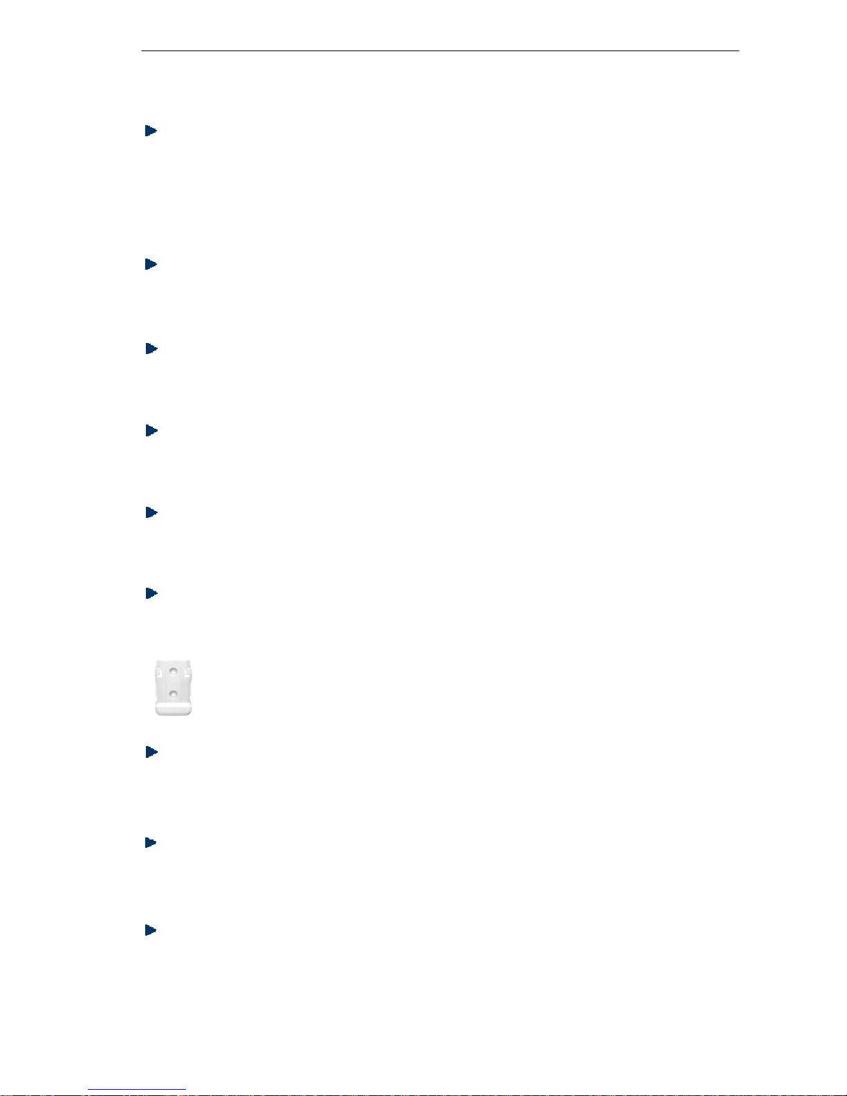
And the infrared controller can be equipped with the controller holder, convenient to fix
the remote controller.
Auto–restart function (optional)
All indoor units have auto-restart function. When the power supply cut off suddenly, the unit will
automatically recover the previous running mode once the power supply is on.
-4-
Self-diagnostic function
In the course of operation, if the failure occurs, the failure code will display on the wired controller or
on the operation panel. Then according to the failure code chart, you can eliminate the failure soon.
Central control function, if connected with a central controller
(This device will be available in the near future). That is convenient for building management.
Weekly timing function, if connected with a detector and a weekly timer
Adjustable heating temperature compensation
In heating and in cooling mode, the temperature compensation can be adjusted by the infrared remote.
controller. If you do not want the compensation, you can set the compensation as 0°C (factory setting).
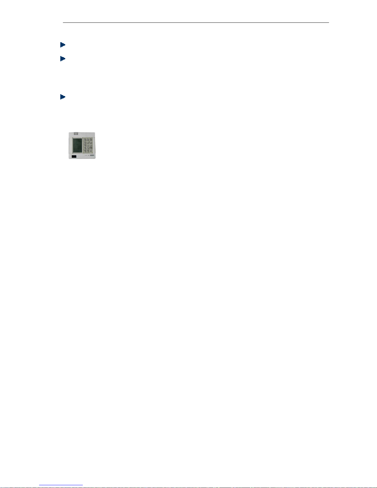
Optional wired controller YR-E12
The wired controller YR-E12 can control a single unit individually, also it can control some units in
group of 16 indoor units. with plenty of functions: refer to the controller function section.
-5-
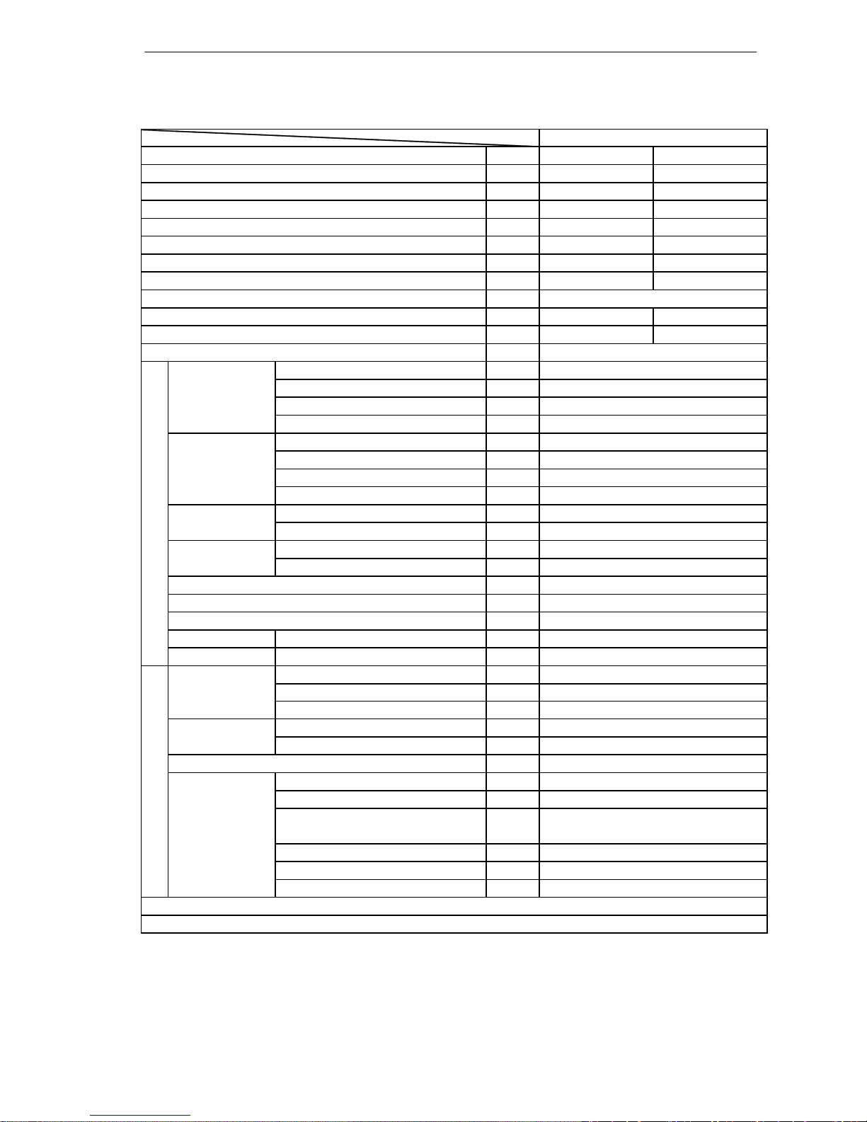
2.1 Outdoor Unit
——
Cooling Heating
W 8000 10000
W 2480 2580
W/W
3.22 3.87
W 1500 1800
W 550 550
W
9500 11500
W
3800 3800
——
A 16.8 16.8
—— 99% 99%
A
Model / Manufacture ——
Oil charge and type ——
Type ——
Number ——
Type × Number ——
Speed r/min
Motor output power W
Air-flows (H/M/L) m³/h
Type / Diameter mm
Face area m²
External mm
Package mm
——
——
W
Noise level H/M/L dB(A)
Weight Net / Shipping kg / kg
Type / Charge kg
No need to recharge m
Recharge g/m
Liquid mm
Gas mm
——
Drop between IU & OU
m
Piping length between IU & OU
m
Total liquid piping length
m
Max.Drop between IU &OU m
Max.Drop between IU & IU m
Max.Piping length between IU & OU m
Max.Total length
m
Connecting method
Flared
Between I.D &O.D
≤5
≤10
≤40
10(indoor unit lower than outdoor unit)
15 (indoor unit higher than outdoor unit)
25
60
58/-/-
74 / 89
Piping
Refrigerant R410A / 2.6
40
20
Pipe 4* Φ6.35
4* Φ9.52
Defrosting method
Automatic by reversible cycle
Crankcase heater power
35
Dimension
(L×W×H)
1068x340x830
1100x440x979
Refrigerant control method
EEVs
about 4000
Heat exchanger TP2M / 7.0
about 0.75
Outdoor unit
Compressor TNB220FLBM1/MITSUBISHI ELEC.
670CC
Twin Rotary (DC inverter)
1
Fan Axial × 1
850/700/500
60
Max.Running current
Power factor(under rating power input)
Fuse size (recommended size)
30
Maximum capacity
Maximum power input
Power source
1PH, 220-230V~, 50Hz
1. The above performance data are from the combination of HCNL 821 XMR+3*HKEL 201 XMR+1*HSF 411 XMR.
2. Large drop and long piping installation will obviously reduce the total capacity.
Item Model HCNL 821 XMR
Function
Rating capacity
Power input
EER / COP
Minimum capacity
Minimum power input
-6-
-7-
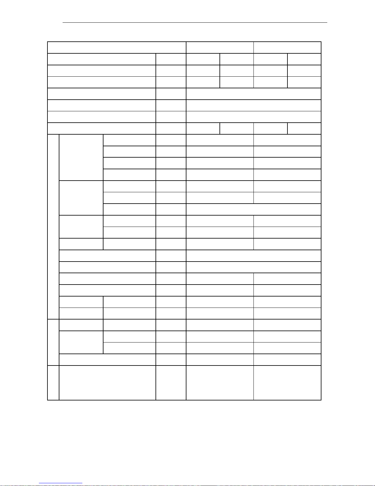
—— Cooling Heating Cooling Heating
W 4100 4600 5000 5500
10‐³×m³/h
1.6 / 2 /
——
——
N, V, Hz
A 0.45 0.45 0.45 0.45
Type × Number ——
Speed r/min
Motor power W
Air-flows (H/M/L) m³/h
Type / Diameter mm
Total area m²
Temp. scope
℃
External mm
Package mm
Drainage pipe material, diameter mm
——
——
mm
——
Noise level H/M/L dB(A)
Weight Net / Shipping kg / kg
Refrigerant Type ——
Liquid mm
Gas mm
——
* o.d.=outer diameter; i.d.=inner diameter
Connecting method Flared Flared
28.3/34.3 28.3/34.3
Piping
R410A R410A
Pipe
6.35 6.35
12.7 12.7
Electricity Heater / /
48/45/41 48
/45/41
EEV on outdoor unit
Fresh air hole dimension / /
990/655/199
1150/750/300 1150/750/300
PVC, 20/18(o.d./I.d.*) PVC, 20/18(o.d./I.d.*)
700/640/580
Heat exchanger
TP2M / 7x0.35 TP2M / 7x0.35
about 0.49 about 0.49
cooling: 6~7 / heating: 43~60
CENTRIFUGAL × 2
1150/1050/850 1150/1050/850
output: 28/input: 80 output: 28/input: 80
Running current
Fan
CENTRIFUGAL × 2
700/64
0/580
Dimension
(L×W×H)
990/655/199
Controller type Infrared YR-H71 or wired YR-E12
Refrigerant control
Communication cable
2x(0.75~1.25mm2 ), must be shielded
Power source 1, 220~230, 50
Dehumidifying capacity
Item
Power cable 3 × 0.75mm
2
HSFL 411 XMR HSFL 531 XMR
Function
Capacity
2.2 Indoor Units
Norminal conditions: indoor temperature (cooling): 27℃DB/19℃WB, indoor temperature (heating):
20℃DB.
Outdoor temperature (cooling): 35℃DB/24℃WB, outdoor temperature (heating): 7℃DB/6℃WB.
The noise level will be measured in the third octave band limited values, using a Real Time Analyser calibrated sound intensity meter. It is a sound pressure noise level.
SAFETY INSTRUCTIONS
• Please read carefully the following Safety Instructions before operating the air conditioner.
• A strict observance of the Instructions indicated on the “USER’S MANUAL” will prevent personal hurt
and incidents to the User. Moreover, correct operation and long life of the system will be ensured.
• Depending on the seriousness of potential risks and damages, the reported Instructions are classied
in two types: “WARNING” and “CAUTION”. A strict observance of the Instructions is required to guarantee your personal safety and the safety of the environments where Units have been installed.
• The following Instructions are related to the air conditioner’s installation. They have been reported in
this “USER’S MANUAL” just to allow the User to check that installation is or has been properly carried
out. If an improper installation - not corresponding to the Instructions - is veried, please contact the
Dealer or the Authorized Technical Service.
The User must never attempt to repair, install or perform special maintenance by himself.
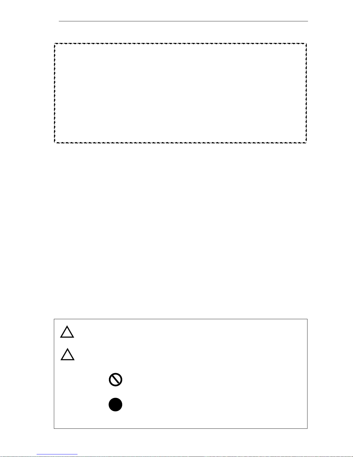
Key to symbols
WARNING
This symbol points out the risk of serious injury or death.
This symbol points out the risk of injury or damage to the property.
Prohibition. Action or procedure not allowed, with serious effects for
people or objects.
CAUTION
Obligation. Compulsory action or procedure. The missed observance
could bring to serious effects for people or objects.
!
!
!
• Strictly observe the instructions provided in this Manual.
• The air conditioning system contains in its refrigerant circuit the R410A gas under
pressure. Never disconnect refrigerant pipes or connection joints.
• Never perform any handling on Outdoor Unit service valves or on Indoor Unit's
unions.
• Keep this Manual in a safe place easy to reach at any time for convenient
reference.
• In case the air conditioner is transferred and reinstalled, this User's Manual should
always be attached to the appliance.
3. Safety precautions
-8-
- 9 -
Installation
Never try to install this Unit by yourself, i.e. without the support of Technical Personnel. Never try to repair the
Unit by yourself. The Unit’s components can be reached only by opening or removing the covering panels,
and this involves exposure to high voltage. Even by disconnecting power supply, it is not always possible
to avoid the risk of electric shocks.
• Please always contact the Dealer or Authorized Service Center for installation.
Never attempt to install the air conditioner by yourself, because improper installation could
cause electric shock, injuries, water leakage or re.
• Please always contact the Dealer or the Authorized Service Center for any servicing
operation or special maintenance.
Never try to repair or carry out special maintenance by yourself. Improper repair or maintenance
could cause electric shock, injuries, water leakage or re.
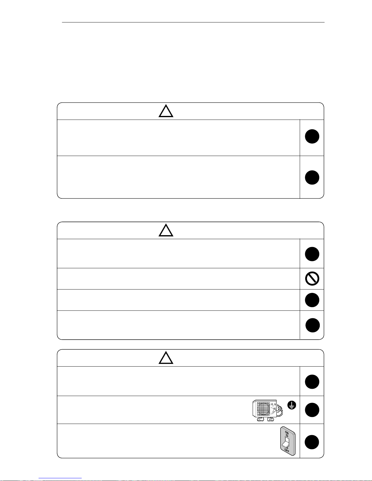
Conrm that installation has been carried out according to the following prescriptions:
WARNING
!
!
!
• When installing, all possible countermeasures must be taken to avoid refrigerant gas leaks.
If there is high concentration of refrigerant gas in the room, oxygen lack may occur.
• Do not install the air conditioner near burners, heat sources or ammable gas. This is to avoid
the risk of malfunctioning, re or explosion.
• Ensure that a circuit breaker has been installed on the power supply line above the air conditioner, to avoid the risk of electric shock.
• When installing in a small room, countermeasures should be taken in case a refrigerant leak
exceeds the proper range. Otherwise, it will cause people asphyxia.
CAUTION
!
!
!
!
• Ensure that drain hose and drain pipe installation has been correctly carried out. Incorrect
installation or maintenance will cause water leakage.
CAUTION
!
!
!
• Ensure that Indoor and Outdoor’s Units have been properly grounded.
Defective grounding could cause electric shock.
!
• This kind of appliance needs a specic circuit breaker with proper protective devices against overcurrents and short circuits (fuses or automatic
switches).
Circuit
breaker
(specic)
Safety precautions
- 10 -
Do not insert the air conditioner’s plug into
multiple sockets or into sockets to which other
appliances are connected. Do not use plug
adapters.
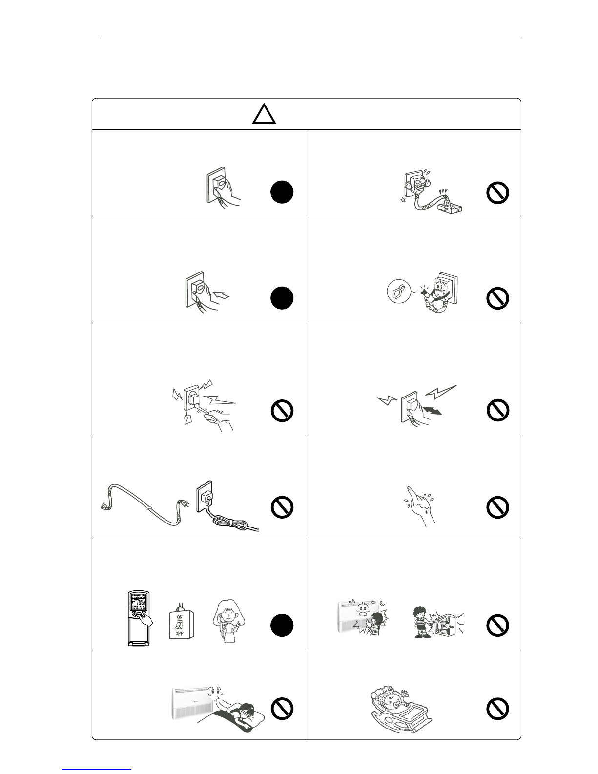
Always observe the operating precautions listed in the following tables. In this way, correct operation and
safeguard of people, animals and objects inside air-conditioned environments will be ensured.
WARNING
!
Use the correct voltage and frequency for power
supply.
!
!
!
Fully insert the plug into the power socket and
make sure the connection is secure and without
play. Otherwise, sparks and re may occur.
Do not put heavy objects on the power supply
cord. Take care not to damage it. Do not use
faulty or damaged power supply cords.
Do not pull out the plug from the power socket
by drawing the power cord. Damaging to the
power cord, to the plug or to the socket may
occur, and this could result in electric shock or
re generation.
Never turn off the air conditioner by pulling the
power supply plug out of the socket. This could
cause electric shock or re.
Always press the ON/OFF button on remote
controller.
Do not use extension cords. Do not use rolled
power supply cords.
Never touch switches, sockets or power supply
plugs with wet hands. This could cause electric
shock.
If you smell something burning, immediately turn
off the air conditioner, switch the circuit breaker to
“OFF” or “0” and contact the Authorized Technical
Assistance.
Do not insert any objects into the air inlet or outlet of Indoor and Outdoor’s Units. Even if fans
are stopped, they could automatically start all
at once.
You should avoid to expose your body directly
to cool air for a long time. This may cause you
health problems.
Do not direct the airow towards infants, aged or
disabled people.
220 ÷ 230V~, 50Hz
B A
M D
OFF
A
U
T
O
ON
OFF
TEMP
SWING
FAN
Safety precautions
- 11 -
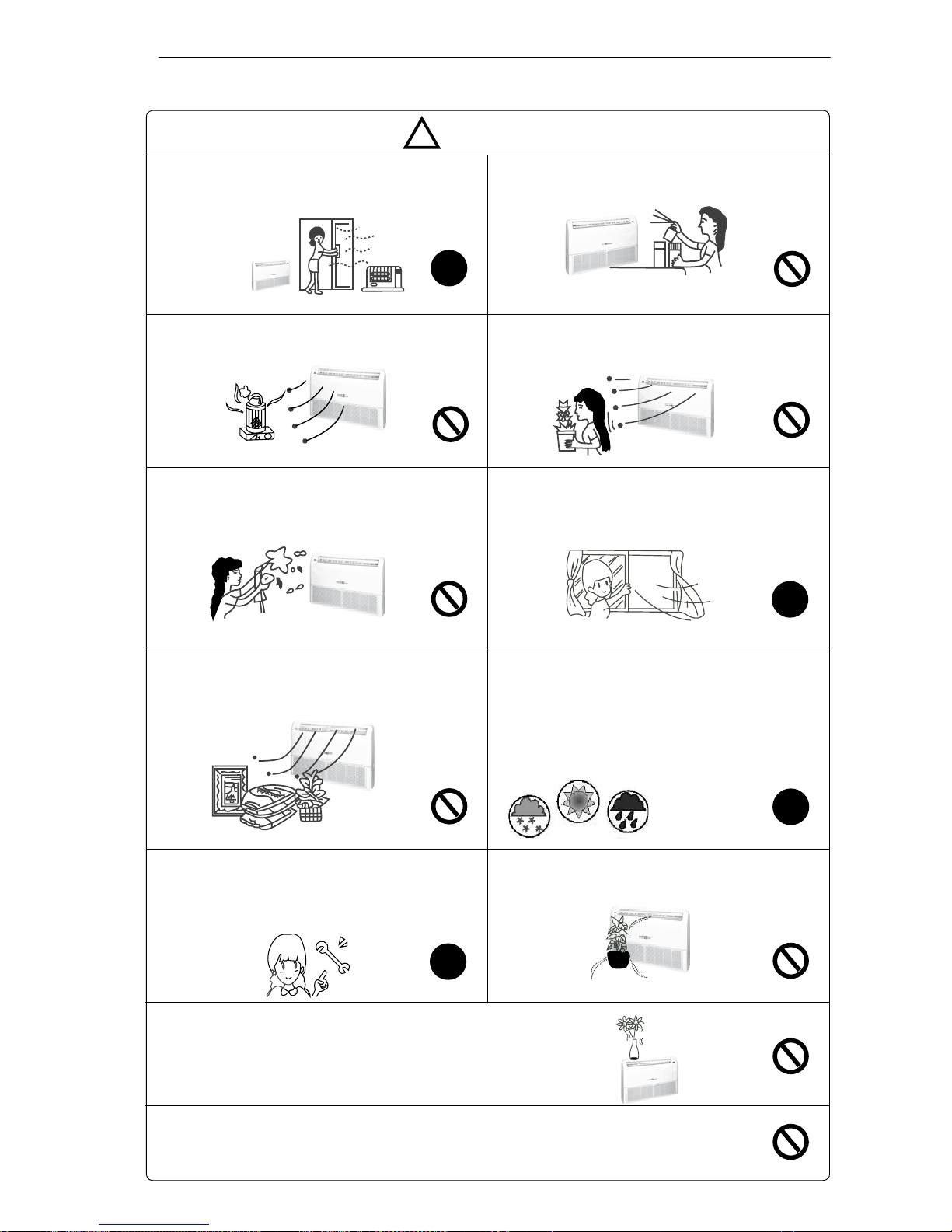
CAUTION
!
Ventilation should be operated when using
at the same time the air conditioner and gas
burners. Insufcient ventilation will cause lack
of oxygen.
Do not use sprayers near the air conditioner and
do not spray anything towards the appliance.
!
!
Do not place burners near the airflow of air
conditioner.
Do not expose plants or animals to the direct
airow of the air conditioner.
To avoid the risk of electric shock, do not sprinkle
water or other liquid on Indoor Unit. Do not clean
the air conditioner by water spurts.
Ventilate the room regularly while the air conditioner is operating. Fail to follow this advice could
result in lack of oxygen inside the room.
Do not expose food, plants, animals, precision
devices or works of art to the direct airow of the
air conditioner.
For prope r perfo rman ce, op erat e the air
conditioner under the temperature and humidity
conditions indicated in this Manual (see page
5, “Recommended Operating Conditions”). If
the Unit operates beyond these conditions,
malfunctions may occur or dew may drip from
the Indoor Unit.
!
Do not place anything in front of the air conditioner
nor obstruct the air outlet.
When necessary, replace fuses with fuses of the
same type and size. Never use a piece of iron
or copper instead of the proper fuse, as it could
result in a malfunction or in a re accident.
!
Do not touch the heat exchangers’ metal aps on Indoor and Outdoor Units. This could cause
hurts due to the sharp shape of the aps. Take care of this especially when removing the inlet
grille and the air lters.
Do not put any object on the air conditioner. On the
appliance’s upper part there is an air inlet grille that must
not be obstructed. Besides, a heavy object may cause the
air conditioner’s fall.
Safety precautions
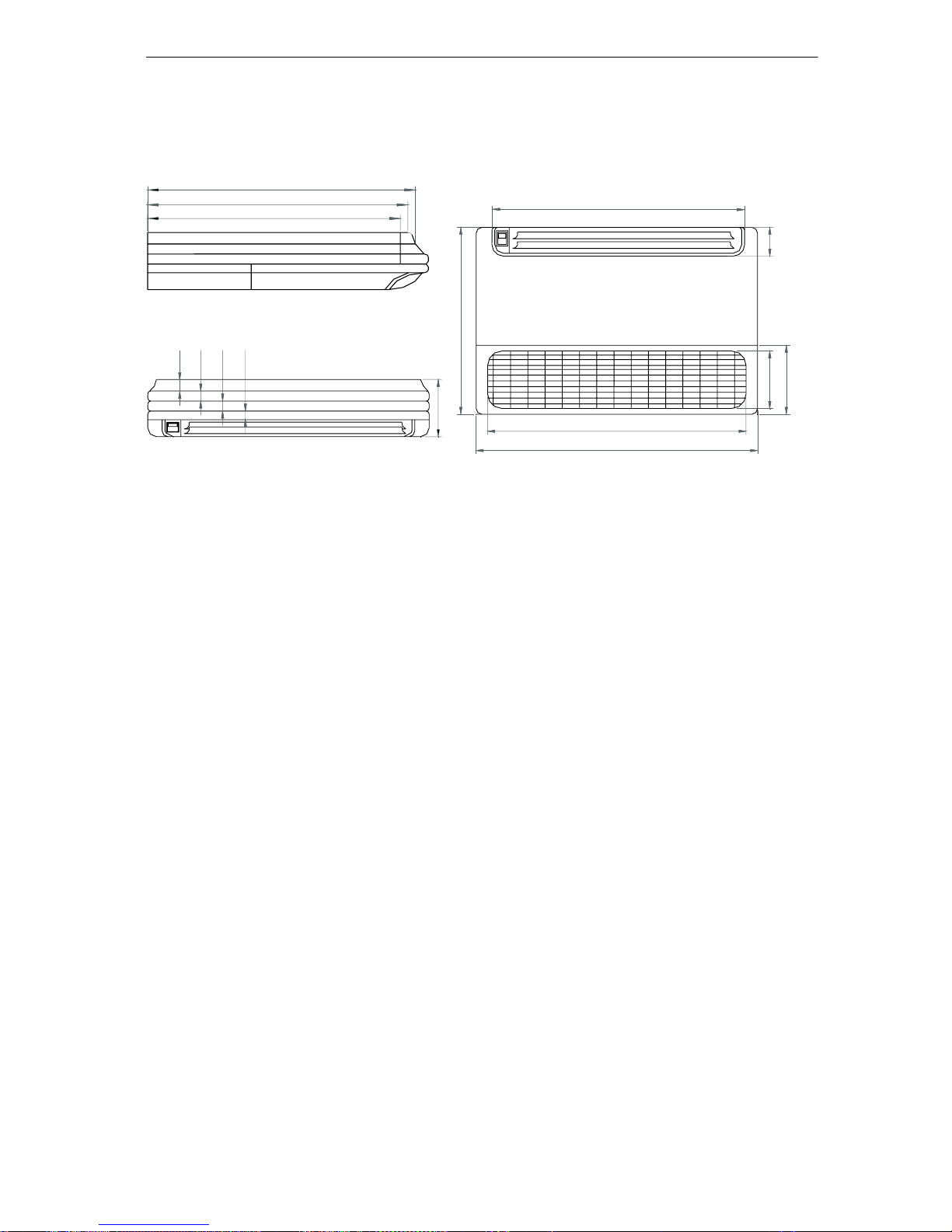
4. Net dimensions of the Indoor Units
Convertible type units: HSFL 411, 531 XMR
-12-
100
900
990
655
200
880
620
605
600
40 35 35 30
199
(mm)
Bhh aha_pne_]h nal]eno iqop ^a _]nnea` kqp ^u
mq]hebea` aha_pne_e]jo1 Jj]`amq]pa nal]eno i]u
naoqhp ej ] i]fkn okqn_a kb `]jcan bkn pda qoan
kbpda]en_kj`epiojan1
Ek jkp `]i]ca ]ju l]npo kb pda ]en _kj`epekjan
pd]p _]nnu nabnecan]jp ^u lean_ejc kn lanbkn]pejc
pda ]en _kj`epekjan,o pq^ao sepd od]nl kn lkejpa`
epaio/ _nqodejc kn pseopejc ]ju pq^ao/ kn
o_n]lejc pda _k]pejco kbb pda oqnb]_ao1 Jb pda
nabnecan]jp olqnpo kqp ]j` capo ejpk auao/ ep i]u
naoqhp ej oanekqo aua ejfqneao1
Ek jkp k^opnq_p kn _kran pda rajpeh]pekj cnehha
kb pda ]en _kj`epekjan1 Ek jkp lqp bejcano kn ]ju
kpdan pdejco ejpk pda ejhap2kqphap ]j` osejc
hkqran1
Ek jkp ]hhks _deh`naj pk lh]u sepd pda ]en
_kj`epekjan1 Jj jk _]oa odkqh` _deh`naj ^a
]hhksa` pk oep kj pda kqp`kkn qjep1
y7-+1.1+~:1659
Uda nabnecan]pejc _en_qep eo ha]g0lnkkb1
41 Bllhe_]^ha ]i^eajp pailan]pqna n]jca=
z0- 4~+015- 19 ~,~7:1<- 15 .6336=15/
91:;~:165
51 Jb pda oqllhu _kn` eo `]i]ca`/ ep iqop ^a
nalh]_a` ^u pda oanre_a ]cajp kn ] oeieh]n
mq]hebea` lanokj1
61 Jb pda bqoa kj QD ^k]n` eo ^nkgaj lha]oa
_d]jca ep sepd pda pula kb U6148B 2583WBD1
Dkkhejc
Ia]pejc
Jj`kkn
Outdoor
S]pa` N]teiqi Nejeiqi
5: 65 4;
4< 56 47
68 76 43
57 59 9
53 5: 48
4718 00 00
: 57 048
94;00
EC D
XC D
EC D
XC D
Jj`kkn
Outdoor
EC D
XCD
Model
Dkiiqje_]pekj _]^ha
-odaeh`a` sena.
Power cable
HSFL411XMR
I38SO0G 6H -40518.ii
5
I38SO0G 5Y-31:80418.ii
5
HSFL531XMR I38SO0G6H-40518.ii5 I38SO0G5Y-31:80418.ii5
5. Installation instructions
71 Uda senejc iapdk` odkqh` ^a ej heja sepd
pda hk_]h op]j`]n`1
91 Uda s]opa ^]ppanu od]hh ^a `eolkoa` lnklanhu1
:1 Uda ej`kkn qjep ejop]hh]pekj daecdp eo ]p ha]op 518i1
;1Uda]llhe]j_aiqop^aejop]hha`so pd]ppdalhqcodkqh`
be a]oehu]__aooe^ha]bpanejop]hh]pekj1
81 Uda lksan _]^ha ]j` _kjja_pejc _]^ha ]na
oahb0lnkre`a`1
Uda namqenaiajp kb pda _kiiqje_]pekj _]^ha=
-13-
EC D
XCD
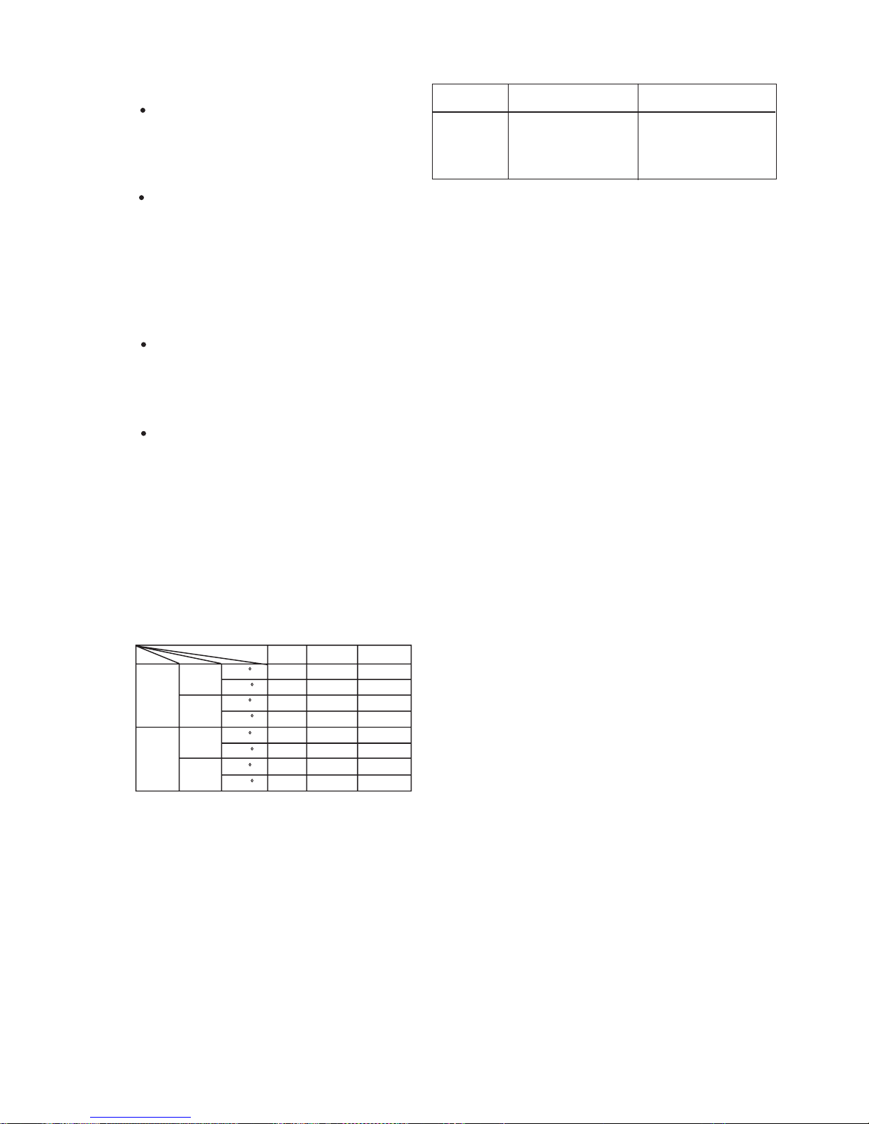
■R410A
The working pressure of R410A is approximately 1.6 times higher than R22. Because the oil in the
refrigerant is different, please do not mix them.
Refrigerant R22 (single) R410A (mixed) R407C (mixed)
Oil Mineral oil (SONTEX 200LT) Synthetic oil (POE oil) Synthetic oil (POE oil)
Pressure ratio 1 Approx. 1.6 Approx. 1.1
■Operation flow
1. Calculate the refrigerant additional charging
amount, and charge a suitable amount.
1. Air purging by refrigerant is prohibited seriously
2. Use a special vacuum pump with reverse check
mechanism
1. Charge the nitrogen to the set pressure
2. 24 hours later,check if the pressure in the pipe
has reduced
1. Do not connect the power supply
1. Use piping material of the specified thickness
2. Do not use dirty pipe
3. Always flow nitrogen during welding work
hand over
trial running and adjustment
maintenance panel installation
gas leakage check
additional refrigerant charging
evacuation and drying
leakage test
refrigerant piping connection
outdoor unit installation
outdoor unit foundation work
electric wiring work
remote controller installation
insulation work
duct work
drain piping work
refrigerant piping work
indoor unit installation
operation chart preparation
1. Always inspect the used refrigerant
2. Always use the specified refrigerant
refrigerant inspection
prepare work schedule
-14-
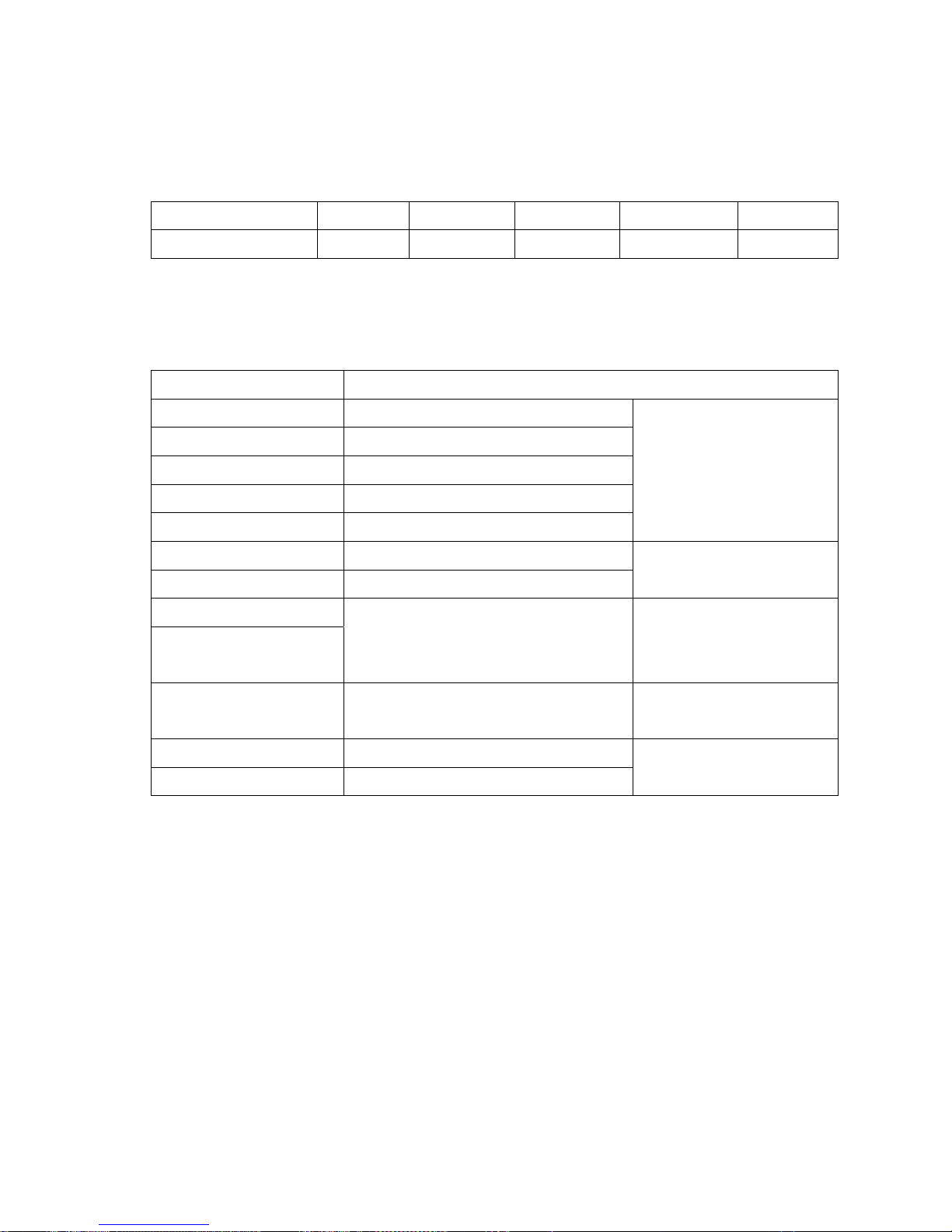
■Piping material
1. Use the correct refrigerant piping and materials for R410A
2. For the pipe wall thickness, see the table below:
Pipe diameter Φ6.35 Φ9.52 Φ12.7 Φ15.88 Φ19.1
Pipe wall thickness 0.8 0.8 0.8 1.0 1.2
Note: Always observe and comply with the local regulations when installing the refrigerant piping.
■Tools
R410A work requires a number of special tools (* symbol). Since the tools used in R22 work
cannot be used for R410A, provide the tools separately.
Tool name Process and application
Pipe cutter Piping cutting
*Flaring tool Pipe flaring work
*Torque wrench Flare nut connection
Expander Expansion at pipe connection
Pipe bender Pipe bending work
Refrigerant piping work
Nitrogen gas Pipe oxidation prevention
Welder Pipe brazing
Air tightness test
*Gauge manifold
*Charging hose
Vacuum evacuation and refrigerant
charging operation check
Air tightness test
Refrigerant
additional charging
*Vacuum pump
(with adapter)
Vacuum drying
Electronic scale
Gas leakage detector Gas leakage test
Refrigerant
additional charging
■Work precautions
Refrigerant check: Before work, check the used refrigerant and prepare materials matched to the
refrigerant.
Refrigerant piping: Observe the basics of refrigerant piping to avoid the unnecessary problems. In
addition, when performing the welding work, seal in the nitrogen gas to the pipes, and prevent it
from the oxidation.
Leak pressure detection: Perform seal detection and make sure there is no refrigerant leakage.
Vacuum drying: If the vacuum pump has not the reverse flow check mechanism, use the pump
together with a reverse flow check adapter.
Additional refrigerant: Charge a suitable amount of refrigerant with a special R410A gauge
manifold and charging hose.
-15-

Operation and Performance
*Heating Performance
*Microcomputer-controlled Automatic Defrosting
Heat-pump air conditioners heat your entire room
by recirculating air throughout the room, with the
result that some time may be required after first
starting the air conditioner until the room is heated.
This air conditioner operates on the heat-pump
principle, absorbing heat from outdoor air and
transferring that heat indoors. As a result, the
operating performance is reduced as outdoor air
temperature drops. If you feel that insufficient
heating perfomance is being produced, we
recommend you use this air conditioner in
conjunction with another kind of heating
appliance.
Instructions relating to heating (*) are applicable
to HSFL 411, 531 XMR Indoor Units.
When using the Heating mode under conditions of
low outdoor air temperature high humidity, frost
may form on the outdoor unit, resulting in reduced
operating performance.
In order to prevent this kind of reduced
performance, this unit is equipped with a
Microcomputer-controlled Automatic Defrosting
function. If frost forms, the air conditioner will
temporarily stop, and the defrosting circuit will
operate briefly (for about 7 to 15 minutes).
STANDARD PARTS
The following installation parts are furnished. Use
them as required.
Mark Parts name
Adhesive tape
Saddle (L.S) with screws
Drain hose
Heat insulation material
Piping hole cover
Putty
Plastic clamp
Optional parts
A
B
C
D
E
F
G
Additional information about these models
-16-
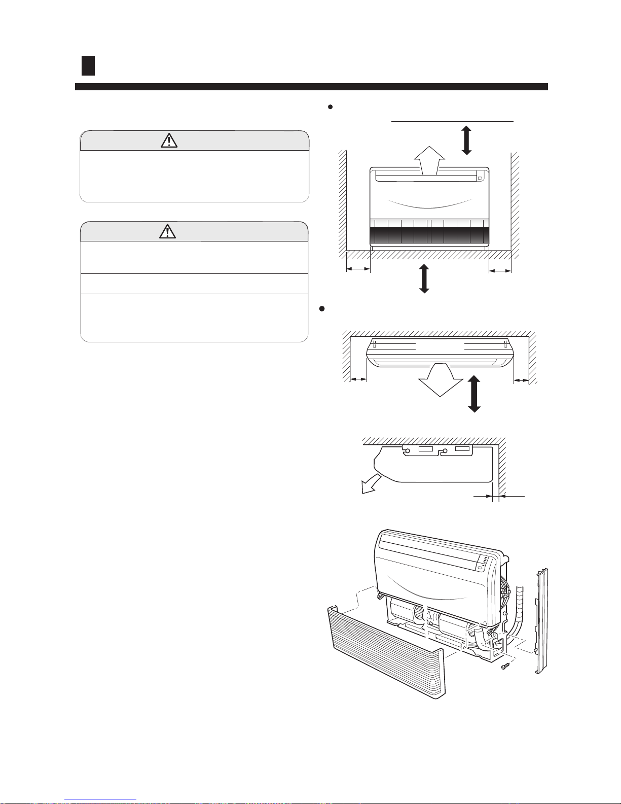
SELECTING THE MOUNTING POSITION
(1)Do not install where there is the danger of com bustible gas leakage.
(2) Do not install near heat sources.
(3) If children under 10 years old may approach
the unit, take preventive measures so that they
cannot reach the unit.
Install at a place that can withstand the weight of
the indoor and outdoor units and install positively
so that the units will not topple or fall
WARNING
CAUTION
Decide the mounting position with the customer as follows:
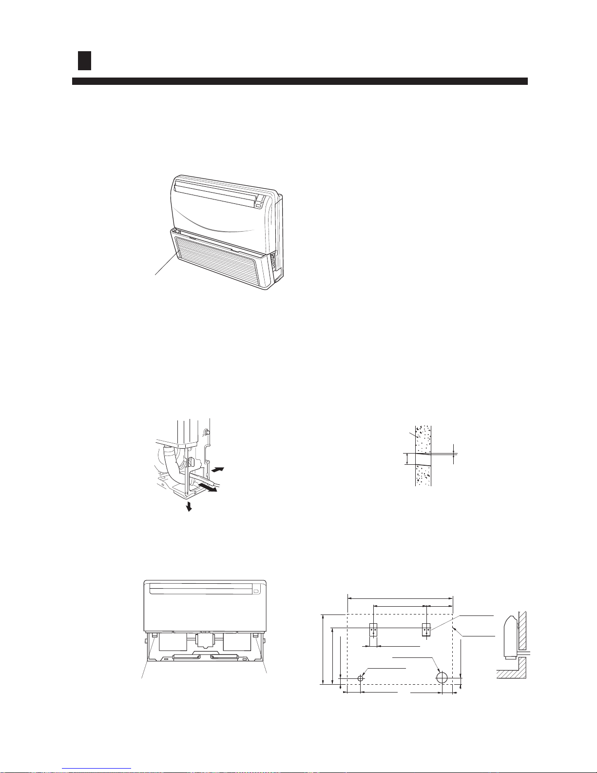
INDOOR UNIT
(1) Install the indoor unit level on a strong wall, floor,
ceiling which is not subject to vibration.
(2) The inlet and outlet ports should not be obstructed:
the air should be able to blow all over the room.
(3) Install the unit near an electric outlet or special
branch circuit.
(4) Do not install the unit where it will be exposed to
direct sunlight.
(5) Install the unit where connection to the outdoor
unit is easy.
(6) Install the unit where the drain pipe can be easily
installed.
(7) Take servicing, etc. into consideration and leave the
spaces shown in Fig.A. Also install the unit where
the filter can be removed.
Under ceiling
2 cm
or more
Ceiling
Indoor unit
30 cm
or more
Left
Right
1.5m
Floor console
30 cm
or more
30 cm
or more
1.5m
1.5m
Left
Right
may be difference
Fig.A
Indoor unit
Installation of the Indoor Unit
-17-
ELECTRICAL WIRING
(1) The power source capacity must be the sum of the
room air conditioner current and the current of other
electrical appliances. When the current contracted
capacity is insufficient, change the contracted
capacity.
(2) When the voltage is too low and the air conditioner
is difficult to start, contact the power company the
voltage raised.
CAUTION
TEST RUNNING
1. CHECK ITEMS
(1) INDOOR UNIT
(1) Is operation of each button on the remote control
unit normal?
(2) Does each lamp light normally?
(3) Do not air flow direction louvers operate normally?
(4) Is the drain normal?
(2) Air filter removal and cleaning, and how to use
air louvers.
(3) Give the operating and installation manuals to
the customer.
(1) Always use a special branch circuit and install a special
receptacle to supply power to the room air conditioner.
(2) Use a circuit breaker and receptacle matched to
the capacity of the room air conditioner.
(3) The circuit breaker is installed in the permanent wiring.
Always use a circuit that can trip all the poles of the
wiring and has an isolation distance of at least 3mm
between the contacts of each pole.
(4) Perform wiring work in accordance with standards so
that the room air conditioner can be operated safely
and positively.
(5) Install a leakage circuit breaker in accordance with the
related laws and regulations and electric company
standards.
WARNING
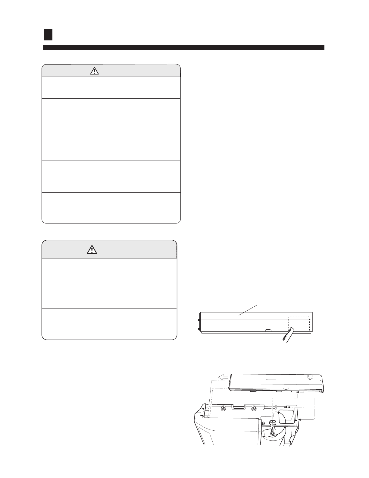
MOUNT THE COVER PLATE AND
THE INTAKE GRILL
(2) OUTDOOR UNIT
(1) Is there any abnormal noise and vibration during
operation?
(2) Will noise, wind, or drain water from the unit disturb
the neighbors?
(3) Is there any gas leakage?
CUSTOMER GUIDANCE
Explain the following to the customer in accordance
with the operating manual:
(1) Starting and stopping method, operation switching,
temperature adjustment, timer, air flow switching,
and other remote control unit operations.
1.Mount the cover plate. (Right)
(1) Cut a pipe exit hole in the right plate. This is
only when the pipe exits from the right side.
(This operation is not required when the
protrusion is on the top or rear.)
Fig. 31
Cover plate (Right)
(2) Join the cover plates (right) and mount with screws.
Fig. 32
Installation procedures
-18-

(2) Insert the hinges on the bottom of the intake grill into the holes in the base assembly. Then mount the arms to
the three areas on the top of the intake grill.
Fig. 35
Fig. 34
(1) Cut the right side of the intake grill. This is only when the pipe exits from the right side
3. Mount the intake grill.
(1) Join the cover plate (left) and mount with screws.
Fig. 33
2. Mount the cover plate.(Left)
Installation procedures
-19-
Open the intake grill and remove the three or four or six screws.(Fig. 1)
Remark:
The main unit can be wired before the indoor
unit is installed. Select the most appropriate
installation order.
A. FLOOR CONSOLE TYPE
1. DRILLING FOR PIPING
Select piping and drain directions.(Fig.2)
The piping and drain can be made in three
directions as shown below.
(Fig.2)
rear
right
down
REMOVE THE INTAKE GRILL
PREPARING INDOOR UNIT INSTALLATION
When installing set to wall, install the accessory wall
bracket at the position shown in Fig.5,and mount the
set to it.
Fig. 1
Intake grill
(Fig. 5)
Wall bracket
Side of set
65.5cm
99cm
50cm
24.5cm
6.5cm
12.5cm 10cm
6.5cm
53cm
4.5cm
7cm hole
3.5cm hole
The drain hose can be connected to either the
left or right side.(Fig.3)
(Fig. 3)
Drain hose (Left side) Drain hose (Right side)
Wall
7cm
6mm
Indoor unit outdoor unit
(Fig.4)
When the directions are selected, drill a 7 cm dia.
hole on the wall so that the hole is tilted downward
toward the outdoor for smooth water flow. When
the pipe is led out from the rear, make a hole in
Fig.4, at the position shown.
Installation of the Indoor Unit
-20-

Select whether the drain hose will be connected
to the left or right side.(Fig.3) Insert the drain
hose into the drain pan, then secure the drain
hose with a nylon fastener. (Fig.6)
2. INSTALLING DRAIN HOSE
(Fig. 6)
Wrap the insulation (drain hose) around the drain
hose connection. (Fig.7)
(Fig. 7)
CAUTION
Do not install the unit drain hose side is too high. Height A should be less than 5 mm.(Fig.9)
Fig. 8
Be sure to arrange the drain hose correctly so that it is leveled lower than the drain hose connecting port
of the indoor unit.
Drain pan
Drain hose
Nylon fastener
Drain pan
Drain hose
Insulation
(Drain hose)
OK NO NO
Arrange the drain hose
lower than this portion.
Drain hose
Fig. 9
A A
Drain hose
B. UNDER CEILING TYPE
Using the installation template, drill holes for
piping and anchor bolts(for holes).(Fig.10)
Installation
template
Wall
Ceilling
Drilling position
for piping
Drilling position
for anchor bolt
200mm
900mm
Fig. 10
Installation of the Indoor Unit
-21-
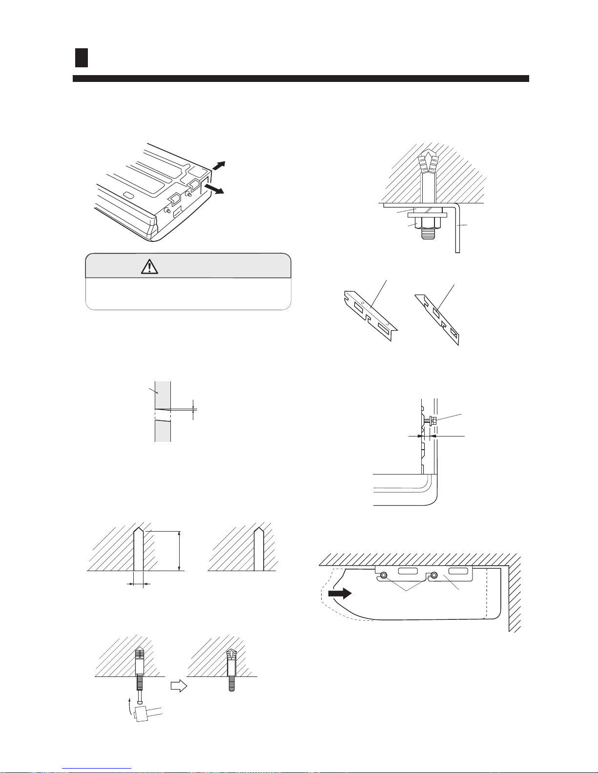
3. INSTALLING BRACKETS
Install the brackets with nuts, washers and spring
washers.(Fig. 15)
4. INSTALLING INDOOR UNIT
Bracket (Right)
Bracket (Left)
Select piping and drain directions.
(Fig.11)
1. DRILLING FOR PIPING
Insert the anchor bolts into the drilled holes, and drive
the pins completely into the anchor bolts with a hammer.
(Fig. 14)
2. DRILLING HOLES FOR ANCHOR BOLTS AND
INST ALLING THE ANCHOR BOLTS
When the directions are selected, drill 80mm and
50mm or 150mm dia. hole on the wall so that the
hole is tilted downward toward the outdoor for
smooth water flow.
With a concrete drill, drill four 12.7 mm dia. Holes.
(Fig.13)
Wall
6mm
Install the drain hose at the rear; it should not
be installed on the top or right side.
Fig. 11
Rear (Install the drain
hose in the direction.)
Right
CAUTION
Fig. 12
Now, securely tighten the hex bolts in both sides.
Fig. 17
Reset the hex bolts as shown in Fig.16.
Hex bolt
8 to 13mm
Indoor unit
Fig. 16
Apply the indoor unit to the brackets.(Fig.17)
Bolt
Bracket
Indoor unit
Fig. 13
60 to 70mm
12.7mm
Fig. 14
Fig. 15
Spring washer
Special nut
Bracket
Installation of the Indoor Unit
-22-
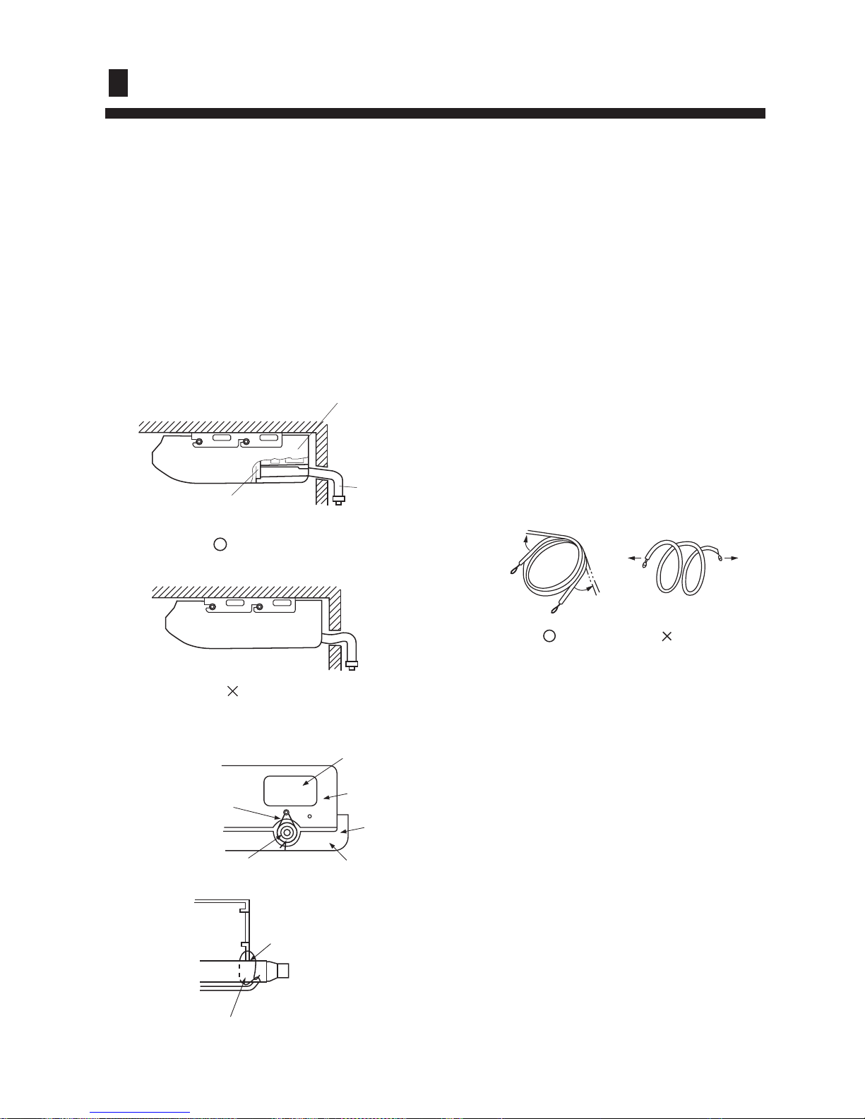
Select whether the drain hose will be connected to
the left or right side.(Fig.3)
Insert the drain hose into the drain pan, then secure
the drain hose with a nylon fastener.(Fig.6)
Wrap the insulation (drain hose)around the drain
hose connection.(Fig.7)
Be sure to arrange the drain hose correctly so that
it is leveled lower than the drain hose connecting
port of the indoor unit.(Fig.18)
5. INSTALL THE DRAIN HOSE
Fig. 18
Pass the drain hose through here
CONNECTING THE PIPING
1. FLARE PROCESSING
(1) Cut the connection pipe with pipe cutters so
that the pipe is not deformed.
(2) Holding the pipe downward so that cuttings
cannot enter the pipe, remove the burrs.
(3) Remove the flare nut from the indoor unit pipe
and outdoor unit and insert the flare nut onto the
pipe, and flare with a flaring tool.
2. BENDING PIPES
The pipes are shaped by your hands. Be careful
not to collapse them.
NO
Remove the hole cover.
OK
Arrange the drain hose
lower than this portion
Drain hose
VT wire
Drain hose
Fig. 19
Piping hole
Base (Bottom)
Intake grill
VT wire hole
Cut the grill
Fig. 21
OK
NO
Extend the pipe by unwinding it
Installation of the Indoor Unit
-23-
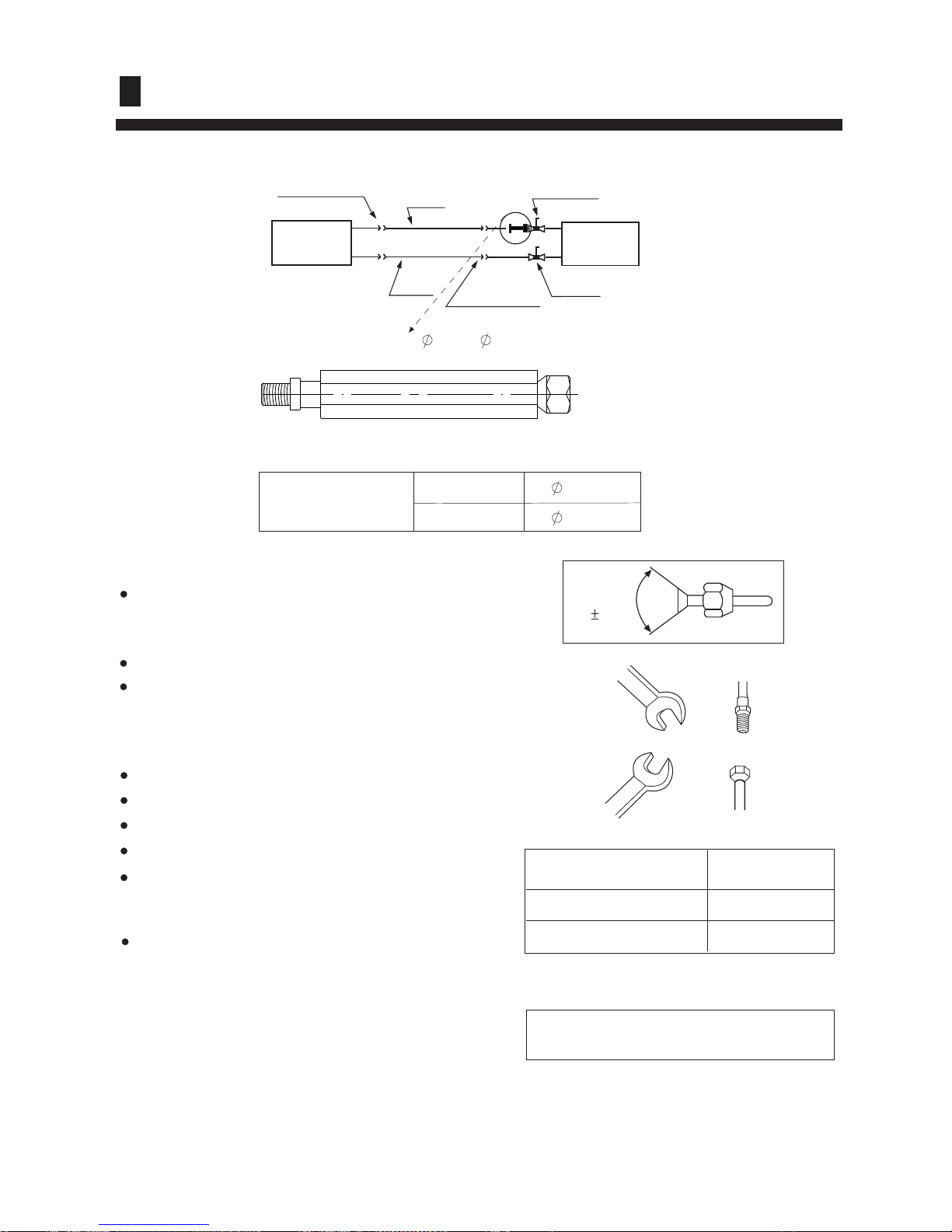
(1) Dimension of connecting pipe
(2) The maximum length and drop height of connecting pipe
Cautions for piping connection
Smear refrigerant oil on the joints of piping and flare.
The bending radius shall be as large as possible.
Align the pipe center when fastening, and tighten the
nut, as shown in the figure.
Pay attention to not mix foreign matters such as sands
in.
Do not twist or deform the connecting pipe.
Do not mix dusts.
The bending radius shall be as large as possible.
Both gas pipe and liquid pipe shall be heat insulation.
No leakage in the flare.
(3) Piping connection
Connecting method
Spanner
Spanner
Joint
Nut
If not aligned ,tighten the nut by force will
damage the nut that result in gas leakage
Please refer to the installation manual of outdoor unit
To ensure the efficiency , Pipes shall be as short as possible.
Fit the nut on and fasten
HSFL 411XMR
HSFL 531XMR
Flare connection
Gas pipe
3-way valve
Indoor
Unit
Outdoor
unit
Liquid
pipe
2-way valve
Flare connection
A
Diameter of Pipe
Liquid Pipe 6.35mm
Gas Pipe 12.7mm
Tighten Torque
(N. m)
11.8
49.0
A(adaptor, from 9.52 to 12.7)
To outdoor unit
To gas pipe
90 0.5
O
Gas pipe
Liquid pipe
12.7mm
6.35mm
HSFL 411XMR
HSFL 531XMR
3. PIPING CONNECTION
-24-
Installation of the Indoor Unit
HOW TO CONNECT WIRING TO THE TERMINALS
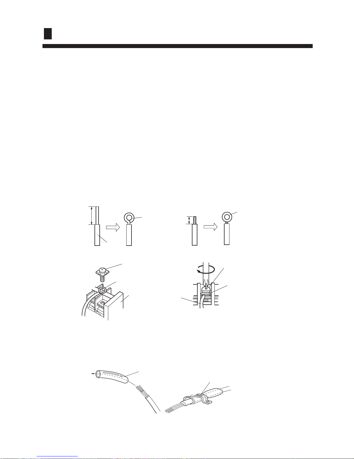
A. For solid core wiring (or F-cable)(Fig.24A)
(1) Cut the wire with a wire cutter or wire-cutting pliers, then strip the insulation to about 25mm of the
exposed solid wire.
(2) Using a screwdriver, remove the terminal screw(s) on the terminal board.
(3) Using pliers, bend the solid wire to form a loop suitable for the terminal screw.
(4) Shape the loop wire properly, place it on the terminal board and tighten securely with the terminal
screw using a screw driver.
B. For strand wiring(Fig.24B)
(1) Cut the wire with a wire cutter or wire-cutting pliers, then strip the insulation to about 10mm of the
exposed strand wiring.
(2) Using a screwdriver, remove the terminal screw(s)on the terminal board.
(3) Using a round terminal fastener or pliers, securely clamp a round terminal to each stripped wire end.
(4) Position the round terminal wire, and replace and tighten the terminal screw using a screw driver.
After passing the connection cord and power cable through the insulation tube, fasten it with the cord
clamp, as shown in Fig.25
HOW TO FIXED CONNECTION CORD AND POWER CABLE AT
THE CORD CLAMP
Fig. 25
Insulation tube
Cord clamp
Use VW-1, 0.5 to 1.0 mm thick, PVC tube as the insulation tube.
Fig. 24
Insulation
Strip 25mm
Loop
A. Solid wire
Terminal
board
Screw with
special washer
Round
terminal
Wire
Screw with
special washer
Round
terminal
Wire
Strip 10mm
Round
terminal
B. Strand wire
-25-
Installation of the Indoor Unit
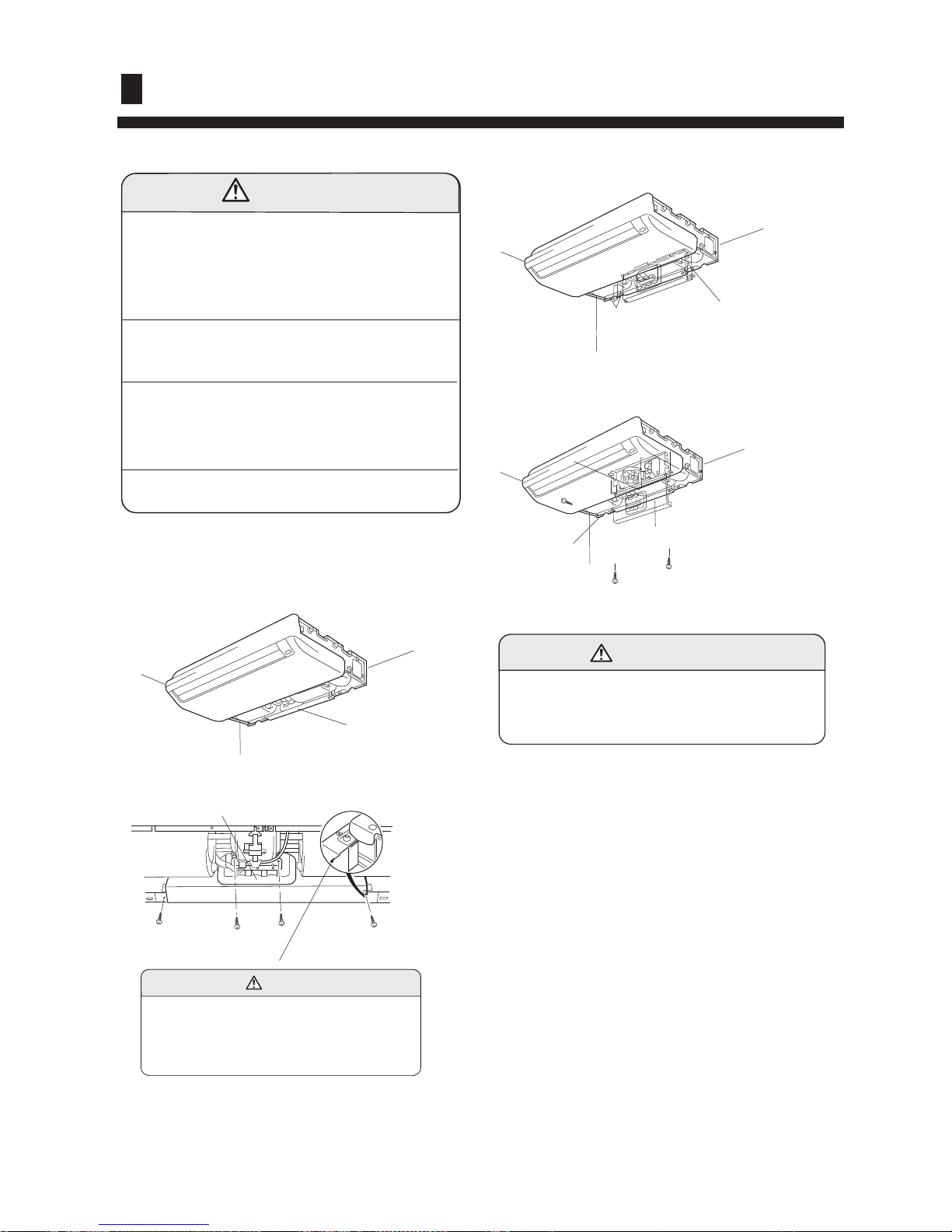
ELECTRICAL WIRING
1. INDOOR UNIT SIDE
(1) Remove the electric component box.
(2) Pull out the electric component box.
(3) Remove the electric component box cover.
Remove the three tapping screws.
(1) Remove the cord clamp.
(2) Process the end of the connection cords to the
dimensions shown in Fig.34.
(3) Connect the end of the connection cord fully into the
terminal block.
(4) Wiring
(4) Fasten the connection cord with a cord clamp.
(5) Fasten the end of the connection cord with the
screw.
Be careful not to pinch the lead wires between the
electric component box and base.
CAUTION
(1) Match the terminal block numbers and connection
cord colors with those of the outdoor unit.
Erroneous wiring may cause burning of the electric
parts.
(2) Connect the connection cords firmly to the terminal
block. Imperfect installation may cause a fire.
(3) Always fasten the outside covering of the connection
cord with the cord clamp.(If the insulator is chafed,
electric leakage may occur.)
(4) Always connect the ground wire.
Do not remove the screws. If the screws
are removed, the electric component box
will fall.
Fig. 26
Electric component box
Remove the four tapping
screws.
Fig. 27
Electric component box
CAUTION
Fig.28
Electric component box
Fig. 29
Base
Electric component box cover
CAUTION
-26-
Installation of the Indoor Unit
41Vebob ^ob qtl jbqelap ql pbq qeb `ljjrkf`^qflk ^aaobpp
C1Wpbqebobjlqb`lkqoliibo -abc^riqpq^qrpfkcfopqfkpq^ii^qflk.1
D1 Wpb afm ptfq`ebp lk qeb fkallo rkfq RED1
METHOD 1: Address setting procedure using the infrared remote controller YR-H71.
C1 Ubq qeb ^aaobppbp lkiv ^cqbo qeb pr``bppcri fkpq^ii^qflk lc qeb obcofdbo^kq mfmbp ^ka `lkkb`qfkd `^_ibp/ ^ka
lmbk ^ii qeb pqlm s^isbp>
D1 Rib^pb `lkcfoj qe^q qeb fkallo rkfqp ^ka qeb lrqallo rkfq fk qeb p^jb pvpqbj rpb qeb p^jb mltbo plro`b>
E1 Rltbo lk qeb rkfqp/ _rq mrq ^ii qeb fkallo rkfqp fk qeb pq^qrp lc UVCPFD[>
F1 Rib^pb klqb qe^q qeb ^aaobpp jrpq _b pbq ^p cliiltfkd=
Q[U\\] `[X_ _WR_ T\[[VT_ _\ aRYaV MG _WV RUU]V^^ Z`^_ SV HL
Q[U\\] `[X_ _WR_ T\[[VT_ _\ aRYaV NG _WV RUU]V^^ Z`^_ SV IL
Q[U\\] `[X_ _WR_ T\[[VT_ _\ aRYaV OG _WV RUU]V^^ Z`^_ SV JL
Q[U\\]`[X__WR_T\[[VT__\aRYaVPG_WVRUU]V^^Z`^_SVKL
ð
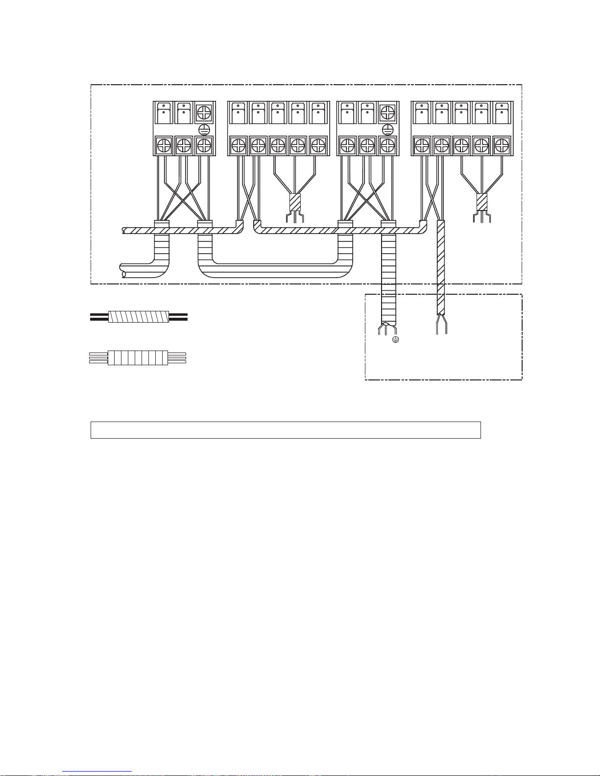
IMPORTANT: Indoor Unit communication address setting
FDVULQP8IDLNUQGQUKLT<UKHVPLUXLNNPQUXQSM>
t Example of wiring for the Indoor Unit
Veb afpq^k`b _bqtbbk qeb pfdk^i tfobp ^ka qeb mltbo `^_bp pelria _b ^q ib^pq 83jj1
E
DC
S
R
4-N. 5-P. 5-P.4-N.
R
S
CD
E
L N C1(P) C2 (Q)
-Kk `^pb lc rpfkd tfoba
`lkqoliibo YR-E12.
Vl lqebo
fkallo rkfq
Vl tfoba `lkqoliibo
Vl lrqallo rkfq
Eljjrkf`^qflk `^_ib -Uefbia tfob.=
J38TP0H 5Z -31:80418.jj
5
Rltbo `^_ib = J38TP0H 6I -40518.jj
5
G1Gu^jmib=pbqrkfqCql^aaobpp41
Elkqfkrlrpiv mobppqebbjbodbk`v ptfq`eclo^_lrq48pb`lkap/until qeb_rwwbotfiiplrka7qfjbp-RKRKRKRK.
and then release the switch. At this time the indoor unit has entered the address setting procedure. But the LED
display shows nothing.
H1 Wpb qeb `lkqoliibo ql qrok lk qeb fkallo rkfq1 Cq qefp qfjb/ qeb `lkqoliibo pelria _b `e^kdba colj QHH ql
QP/^kaqebkqeb VKOGTNGFciapebplk`b1Ve^qfpqlp^v/qeb^aaobpppbqqfkdfpbk^_iba1
I1Robppqeb_rqqlk +UNGGR+lkqeb`lkqoliibo/qebqfjbpvlrmobppfqpq^kapcloqeb^aaobppvlrt^kqqlpbq/
abq^fiba ^p cliiltfkd=
Robpp _rqqlk + UNGGR + lk`b/ qeb ^aaobpp fp +4 +/ ^ka qeb VKOGT NGF ci^pebp lk`b>
Robpp _rqqlk + UNGGR + qtf`b/ qeb ^aaobpp fp+5+/^kaqebVKOGT NGF ci^pebp qtf`b>
-27-
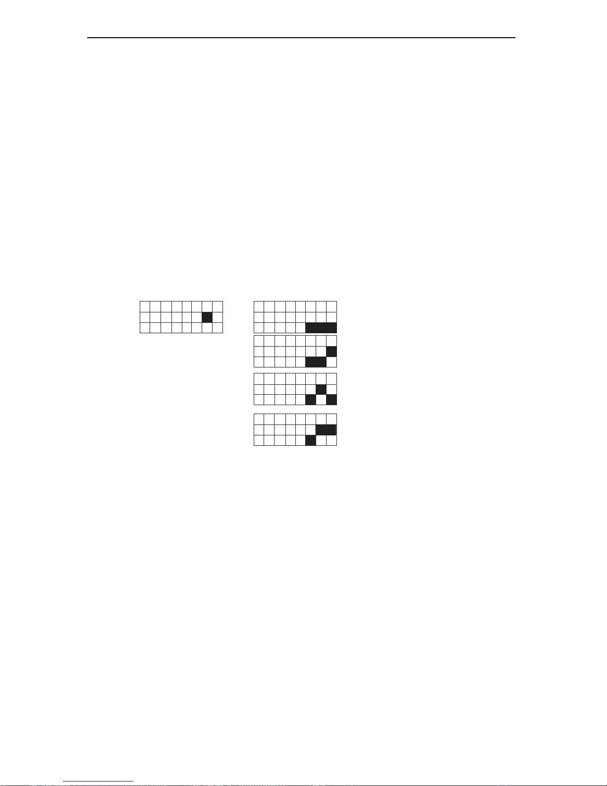
61 B``naoo oappejc lnk_a`qna sdaj qoejc pda EJQ osep_dao TX34 ]j` TX361
B1 Uda EJQ osep_dao TX34 ]j` TX36 ]na kj pda ej`kkn qjep QDC1
C1 Cabkna _]nnuejc kqp pda ]``naoo oappejc skng/ pda ouopai iqop ^a lksana` kbb1
D1 U]ga kbb pda bnkjp l]j]h ]j` pda behpano/ pdaj p]ga kbb pda bh]lo ]j` ]hok pda bnkjp _kran/`eo_kjja_p pda osejc
ikpkn _kjja_pkno bnki pda QDC ]j` pdaj p]ga kqp pda hksan l]np kb pda QDC1
E1 Dd]jca pda lkoepekj kb EJQ : kb TX34 bnki PGG pk PO/ eb b]eh pk `k pdeo/ pda ]``naooao oap ^u TX36 sehh
jkp skng1
F1 Voa TX36 pk oap pda ]``naooao ]o bkhhksejc -EP OPU DIBOHF PUIFS EJQ TXJUDIFT.=
71 Iks pk _da_g pda ]``naooaoA
Xdaj bejeod ]hh pda ]^kra skngo/ lha]oa lksan kbb ]j` lksan kj ]c]ej pk pda sdkha ouopai ^qp oap ]hh
pda ej`kkn qjepo ej TUBOECZ1 Udaj _kjpejkqohu lnaoo pda aiancaj_u osep_d qjpeh ukq da]n pda ^qvvan
okqj` 8 peiao-Qe Qe Qe Qe Qe./ ]j` pdaj pda UJNFS MFE ^k]n` sehh odks pda ]``naoo kb pdeo ej`kkn qjep1
Pressing the ON/OFF button on the remote controler will exit the address setting procedure.
Qnaoo ^qppkj + TMFFQ + pdnaa peiao/ pda ]``naoo eo+6+/]j`pdaUJNFS MFE bh]odao pdnaa peiao>
Qnaoo ^qppkj + TMFFQ + bkqn peiao/ pda ]``naoo eo+7+/]j`pdaUJNFS MFE bh]odao bkqn peiao>
I1 Voa pda naikpa _kjpnkhhan pk pqnj kbb pda qjep/ Bp pdeo peia/ pda _kjpnkhhan odkqh` ^a _d]jca` bnki PO pk PGG/
]j` pda qjep sehh atep pda ]``naoo oappejc lnk_a`qna/ pda ]``naoo sehh ^a iaikneva`1 Uda MFE ^k]n` sehh ]hs]uo
`eolh]u pda ]``naoo kb pdeo ej`kkn qjep qjpeh pda ouopai ^a lksana` kbb1
J1 Jb ukq s]jp pk _d]jca pda ]``naoo/ lha]oa nala]p pda ]^kra opalo bnki F pk H1
K1 Bbpan oappejc ]hh pda ]``naooao/ lha]oa lksan kbb pda ouopai ]j` pdaj lksan kj ]c]ej1 Ppdanseoa pda ouopai
sehh jkp op]np pk skng1
L1 Pj_a pda ]``naooao ]na oq__aoobqhhu oap/ lha]oa `k jkp _d]jca ep ]ju ikna pk ]rke` _kjbqoekj1
456789:;
PO
PGG
TX34
TX36
456789:;
PO
PGG
PO
PGG
PO
PGG
JOEPPS
VOJU BEESFTT
4
5
6
456789:;
456789:;
456789:;
PO
PGG
7
-28-

10.2 Trial operation
The person who has completed this installation shall be requested to conduct a test operation for check:
Is the temperature adjuster working normally?
Does the location for installation conform to requirements?
Winding up with Protective Plastic Tape.The connection pipes,drain pipe, and the connection wires shall
be wound up with PVC tape.
Notes: The connection pipes shall also be wound up with insulating material to preserve the temperature.
The airing direction shall be from bottom to top.
10. Installation check and trial operation
Check the Layout of the Drain Pipe and Connection Wires, and also the piping and address setting.
The drain pipe should be placed underneath, and the connection wires should be placed upside;
and the drain pipe especially the section inside the machine and indoors must be wound up with
insulating material to preserve heat. The drain pipe shall be sloped and no concave and convex
shall occur along the whole pipe..
10.1 Installation check
Is power supply voltage required?
Is water completely drained to outdoors?
Are power wire and connection wires between indoor and outdoor units correctly connected?
Is any gas leaked from the pipe connectors?
Are series numbers of the terminals on the indoor and outdoor units corresponding to each other?
Is the connection section of the auxiliary pipe insulated? Is the indoor unit fixed firmly?
Is noise excessive?
-29-

Installation of the Outdoor Unit
Disposal of the old air conditioner
Before disposing an old air conditioner that goes
out of use, please make sure it's inoperative and
safe. Unplug the air conditioner in order to avoid
the risk of child entrapment.
It must be noticed that air conditioner system
contains refrigerants, which require specialized
waste disposal. The valuable materials contained
in a air conditioner can be recycled. Contact your
local waste disposal center for proper disposal of
an old air conditioner and contact your local
authority or your dealer if you have any question.
Please ensure that the pipework of your air
conditioner does not get damaged prior to being
picked up by the relevant waste disposal center,
and contribute to environmental awareness by
insisting on an appropriate, anti-pollution method
of disposal.
Disposal of the packaging of your new air
conditioner
All the packaging materials employed in the
package of your new air conditioner may be
disposed without any danger to the environment.
The cardboard box may be broken or cut into
smaller pieces and given to a waste paper disposal
service. The wrapping bag made of polyethylene
and the polyethylene foam pads contain no
fluorochloric hydrocarbon.
Consult your local authorities for the name and
address of the waste materials collecting centers and
waste paper disposal services nearest to your house.
Safety Instructions and Warnings
Before starting the air conditioner, read the
information given in the User's Guide carefully. The
User's Guide contains very important observations
relating to the assembly, operation and maintenance
of the air conditioner.
The manufacturer does not accept responsibility for
any damages that may arise due to non-observation
of the following instruction.
Damaged air conditioners are not to be put into
operation. In case of doubt, consult your supplier.
Use of the air conditioner is to be carried out in
strict compliance with the relative instructions set
forth in the User's Guide.
Installation shall be done by professional people,
don't install unit by yourself.
All these valuable materials may be taken to a waste
collecting center and used again after adequate
recycling.
For the purpose of safety, the air conditioner must
be properly grounded in accordance with
specifications.
Always remember to unplug the air conditioner
before opening inlet grill. Never unplug your air
conditioner by pulling on the power cord. Always
grip plug firmly and pull straight out from the outlet.
-30-

4. The wiring method should be in line with the local
wiring standard.
5. The power cable and connecting cable are selfprovided. All the cables shall have got the local
authentication certificate. During installation, when
the connecting cables break off, it must be assured
that the grounding wire is the last one to be broken
off.
6. The breaker of the air conditioner should be allpole switch; and the distance between its two contacts
should be no less 3mm. Such means for disconnection
must be incorporation in the fixed wiring.
7. The waste battery shall be disposed properly.
All electrical repairs must be carried out by
qualified electricians. Inadequate repairs may result
in a major source of danger for the user of the air
conditoiner.
Do not damage any parts of the air conditioner
that carry refrigerant by piercing or perforating the
air conditioner's tubes with sharp or pointed items,
crushing or twisting any tubes, or scraping the
coatings off the surfaces. If the refrigerant spurts
out and gets into eyes, it may result in serious eye
injuries.
Do not obstruct or cover the ventilation grille of
the air conditioner. Do not put fingers or any other
things into the inlet/outlet and swing louver.
Do not allow children to play with the air
conditioner. In no case should children be allowed
to sit on the outdoor unit.
Specifications
The refrigerating circuit is leak-proof.
1. Applicable ambient temperature range:
The machine is adaptive in following
situation
2. If the supply cord is damaged, it must be replaced
by the manufacturer or its service agentor a similar
qualified person.
3. If the fuse on PC board is broken please change it
with the type of T 3.15A /250V AC or T 25A/250VAC.
Please check the circuit diagram about the fuse
replaced.
Cooling
Heating
Indoor
Outdoor
Indoor
Outdoor
Maximum:D.B/W.B 32 C/23 C
Minimum:D.B/W.B 18 C/14 C
Maximum:D.B 43 C/26 C
Minimum:D.B
Maximum:D.B 27 C
Minimum:D.B 20 C
Maximum:D.B/W.B 24 C/18 C
Minimum:D.B/W.B -15 C
10 C/6 C
Cautions
-31-

Safety precautions
All units shall be earthed. The earth must not be connected to a gas pipe, water pipe, or telephone
line. Poor earthing could cause electric shock.
Be sure to install a circuit breaker to avoid electric shock.
Arrange water drainage according to this manual. Cover pipe with insulation materials to prevent
condensation occuring. Improper installation of water drainage will cause water leakage.
WARNING
Installation work must be carried out by professional qualified people, do not install the unit by
yourself. Incorrect installation will cause water leakage, electric shock and potentially fire.
Install the unit as per the manual. Incorrect installation will cause water leakage, electric
shock or fire risk.
Be sure to use specified accessories and parts. Otherwise, water leakage, electric shock, fire risk
or unit falling down may occur .
Mounting position must be strong enough to hold the unit. Or, the unit will potentially fall down
causing injuries.
When installing the unit, take in consideration storms and high winds. Incorrect installation may
cause the unit to fall down.
All electric work should be carried out by experienced personnel as per current regulations and
this manual. Incorrect installation or undersized electric cable may cause electric shock or fire risk.
All circuits must be earthed. Ensure that no external forces will affect the terminal block and electric
cable. Poor wiring and installation may cause fire risk.
Arrange wire connection between connecting the indoor and outdoor power supply correctly. Fix
terminal cover firmly to avoid overheating, electric shock or even fire risk.
In the case of a refrigerant leakage during unit installation, keep the room well ventilated.
Check the unit upon installation. Be sure there is no leakage. Refrigerant will induce a poisonous
gas subject to heat.
Isolate power supply before touching terminal block.
WARNING
To ensure proper installation, please read this safety precautions carefully before the installation. After
installation, start the unit correctly and ensure that you show the customer how to operate and maintain
the units.
WARNING!
CAUTION!
Incorrect operations may result in injuries or machine damages; in some cases may
cause serious consequences.
Incorrect operations may result in severe consequences of death or serious injuries.
To maintain good picture or reduce noise, keep the unit at least 1m from T.V. or radio,
when installing the communication wire and power supply. (If the radio wave is relatively strong,
1m is not enough to reduce the interference).
Do not install the unit in following places:
(a) Oil mist or oil gas exists, such as kitchen, or, plastic parts may age, or water leakage.
(b) Where there is corrosive gas. Copper tube and welded part may be damaged due to corrosion
causing leakage.
-32-

(c) Where there is strong radiation. It will affect the unit's control system, causing malfunction of the unit.
(d) Where there are flammable gas, dirt, and volatile matter (thinner, gasoline) exist, these items will cause
a fire risk.
The following accessories are supplied together with the outdoor unit.
580
185
185
380
416
Installation dimensions (mm)
Place, robust not causing vibration, where the weight of the unit can be supported sufficiently.
Place, not affected by heat or steam generated in the vicinity, where inlet and outlet of the unit are not
disturbed.
Place, possible to drain easily, where piping can be connected with the outdoor.
For the indoor units: place where cold air can be spread in a room entirely.
Place, nearby a power receptacle, with enough space around. (Refer to drawings).
For the indoor units: place where the distance of more than 1m from televisions, radios, wireless devices
and fluorscent lamps can be left.
For some indoor units: in the case of fixing the infrared remote controller on a wall, place where the indoor
unit can receive signals when the fluorescent lamps in the room are lightened.
Choose the installation place
No.
1
2
3
Quantity
1
4
1
Name of parts
Drainage elbow
Rubber cushion
Clap
Drawing
Installation accessories
950
830
1068
340
-33-

Before inserting power plug into receptacle, check the voltage without fail. The power source is the
same as the corresponded name plate.
Install an exclusive branch circuit of the power.
A receptacle shall be set up in a distance where the power cable can be reached. Do not extend the
cable by cutting it.
Power source
Outdoor unit capacity class
Piping to each indoor unit
Total length of liquid piping between all units
HCNL 821 XMR
25m max.
60m max.
Limitations on the installation
2. Selecting a location for installation of the indoor units
The maxinum allowable length of refrigerant piping, and the maxmum allowable height
difference between the outdoor and indoor units, are listed below.
(The shorter the refrigerant piping, the better the performance. Connect so that the
piping is as short as possible. Shortest allowable length per room is 3m)
1. Precautions on installation
Check the strength and level of the installation ground so that unit will not cause any operating vibration
or noise after installation.
In accordance with the foundation drawing in fix the unit securely by means of the foundation bolts.
It is best to screw in the foundation bolts unit their length are 20 mm from the foundation surface.
-34-

Concerning the piping length information, please refer to the following table.
Descriptions
Standard
A, B, C, D Liquid side
A, B, C, D Gas side
mm
Item
Maximum
Unit
L1 (one way)
L2 (one way)
L3 (one way)
h
H +
H -
mm
m
m
m
m
m
m
Size of the liquid side flare connection
Pipe length when the compressor connects with two indoor units
Drop between every two indoor units
Drop between the outdoor unit and the indoor unit
/
/
Size of the gas side flare connection (*)
Pipe length when the compressor connects with two indoor units
Pipe length when the compressor connects only one indoor unit
Drop between the outdoor unit and the indoor unit
6.35
9.52
L1+L2+L3+L4 m
Total liquid piping length(It is no need to charge additional
refrigerant within this value)
L4 (one way) m Pipe length when the compressor connects only one indoor unit
L1
L2
L4
h
H +
A
B
D
C
L3
1
5
5
10
10
40
10
25
5
15
10
25
25
60
25
Limitations on the installation
H -
10
3. Limitations values on the piping work .
-35

Refrigerant piping work
Forced fastening without careful centering may damage the threads and cause a
leakage of gas.
Pipe Diameter ( ) Fastening Torque
Liquid Side 6.35mm (1/4'')
18N.m
Gas Side 9.52mm (3/8'') 50N.m
3. Attaching Drain-Elbow
If the drain-elbow is used, please attach it as figure.
Flare nutHalf union
Torque wrenchSpanner
Liquid pipe
Gas pipe
6.35mm ( 1/4'' ) x 0.8mm
9.52mm ( 3/8'' ) x 0.8mm
2. Connection of pipe
Apply POE refrigerant oil on half union and flare nut.
To bend a pipe, give the roundness as large as possible not to crush the pipe.
Connecting the pipe of gas side firstly makes working easier.
1. Selection of pipe
To this unit, both liquid and gas pipes shall be insulated as they become low temperature in operation.
Use optional parts for piping set or pipes covered with equivalent insulation material.
-36-
12.7mm ( 1/2'' ) x 0.8mm
Gas Side 12.7mm (1/2'') 55N.m

4. Cutting and Flaring work of piping
Pipe cutting is carried out with a pipe cutter and burs must be removed.
After inserting the flare nut, flaring work is carried out.
Please pour water in the drain pan of the indoor unit, and confirm that drainage is carried out serely
to outdoor.
In case that the attached drain hose is in a room, please apply heat insulation to it without fail.
5. On drainage
Please install the drain hose so as to be downward slope without fail.
Correct
Incorrect
Lean Damage of flare Crack Partial Too outside
Pipe diameter*
Size A (mm)
Liquid side
Gas side
6.35mm(1/4")
9.52mm(3/8")
0.8~1.5
1.0~1.5
A
Flare tooling die
Refrigerant piping work
-37-
Gas side 112.7mm(1/2") 1.0~1.5

In case of gas leakage, tighten
parts of pipe connection. If
leakage stops, then proceed 6
steps.
Purging method: to use vacuum pump
2 way valve
3 way valve
90
0
Service port
90
0
for 6 sec.
6 .Detach the charge hose from the service port, open 2way valve and 3-way. Turn the valve rod anticlockwise
until hitting lightly.
Liquid stop valve
2 way valve
3 way valve
Gas stop valve
Gauge maifold (R410A)
Vacuum pump (R410A)
Open
Close
2 way valve
3 way valve
6
6
2 way valve
3 way valve
Valve rod cap
Valve rod cap
Service port cap
1 .Detach the service port's cap of 3-way valve, the valve
rod's cap for 2-way valve and 3-way valves, connect the
service port into the projection of charge hose (low) for
gaugemanifold. Then connect the projection of charge
hose (center) for gaugemanifold into vacuum pump.
2 .Open the handle at low in gaugemanifold, operate
vacuum pump. If the scale-moves of gauge (low) reach
vacuum condition in a moment, check 1 again.
3 .Vacuumize for over 15min. And check the level gauge
which should read -0.1MPa (-76 cm Hg) at low pressure
side. After the completion of vacuumizing, close the
handle 'Lo' in the vacuum pump. Check the condition of
the scale and hold it for 1-2min. If the scale-moves back
in spite of tightening, make flaring work again, then
return to the beginning of 3 .
4 .Open the valve rod for the 2-way valve to and an angle
of anticlockwise 90 degree. After 6 seconds, close the 2way valve and make the inspection of gas leakage.
5 .No gas leakage?
If it does not stop gas leakage, discharge
whole refrigerants from the service port.
After flaring work again and vacuumize,
fill up prescribed refrigerant from the gas
cylinder.
7 .To prevent the gas leakage, turn the service ports cap,
the valve rod's cap for 2-way valve and 3-way's a little
more than the point where the torque increases suddenly.
CAUTION: If the refrigerant of the air conditioner leaks,
it is necessary to make all the refrigerant out. Vacuumize
first, then charge the liquid refrigerant into air conditioner
according to the amount marked on the name plate.
90
o
10s
6.35mm
(1/4")
2 way valve
3 way valve
2 way valve
3 way valve
9.52mm
(3/8")
6.35mm
(1/4")
9.52mm
(3/8")
To indoor unit C
To indoor unit D
2 way valve
3 way valve
6.35mm
(1/4")
To indoor unit B
9.52mm
(3/8")
2 way valve
3 way valve
To indoor unit A
6.35mm
(1/4")
9.52mm
(3/8")
8 .Take the same steps from 1 to 7 for each way to
ensure a completely vacuum for the whole system.
with no-return adapter
-38-

1. Electric wiring
Note:
The air conditioner must use special circuit , and wiring by the qualified electrician according to the wiring
rules specified in national standard.
The grounding wire and the neutral wire shall be strictly separated. Connect the neutral wire with grounding
wire is incorrect.
The electric leakage breaker must be installed.
All the electric wire must be copper wire.When wiring,there shall keep a proper distance between the
power line and communication wire to avoid twist together. Otherwise,signal disturbance will occur,and
the air conditioner can not operate normally. Power supply: 1PH, 220-230V~, 50Hz.
The wiring method of power line is Y connection. If the power line is damaged, in order to avoid risk
of electric shock, it must be replaced by the manufacturer or its repair center or other similar qualified
person.The connecting cable must be shielded.
Fuse: T3.15A 250VAC T25A 250VAC (Please check with the outdoor unit wiring diagram.)
Please check the circuit diagram about the fuse replaced.
Wiring work
2. Wiring method
Wiring method of orbicular terminals
For the connection wire with orbicular terminals, its wiring method is as shown in
the right figure: remove the connecting screw, put the screw through the ring on the
end of the wire, then connect to the terminal block and fasten screw.
Wiring method of straight terminals
For the connection wire without orbicular terminals, its wiring method is: loosen the
connection screw, and insert the end of the connection wire completely into the Terminal block,
then fasten the screw. Slightly pull the wire outwards to confirm it is firmly held.
Crimp connection method for wires without terminals
Wiring method for
ring terminals
Correct pressing
Wrong pressing
Terminal
block
Pressing
clamps
Do not connect the wire
with same diameter to the
same side
Connect the wire with same
diameter to the two sides of
the terminal
Do not connect two
wires with different
diameters
-39-

3. Wiring method of outdoor unit:
Loosen wire cover and connect the power line and communication wire of indoor unit to the terminal
correspondingly.
Note:
When connecting power line to power supply terminal, please pay attention to the following items:
Do not connect the power line with different dimensions to the same connection wire end.
Improper contact will cause heat generation.
Do not connect the power line with different dimensions to the same grounding wire end.
Improper contact will affect protection.
Keep a proper distance between the communication wire and the power line. Otherwise, abnormal
communication will occur because of disturbance. And also, the communication wires should be
shielded wire, and the shield cover should be grounded on the outdoor unit.
Do not connect the power line to the connecting end of communication wire.
Incorrect connection will cause damage to the connected unit.
4. Wiring method of indoor unit
Crimp connection method for connection wire
After connection, the wire must be fastened by wire cover. The wire cover shall press on the protection
coat of the connection wire, as shown in the figure on the previous page.
Note: When connecting the wiring, confirm the terminal number of indoor and outdoor units carefully.
Incorrect wiring will damage the controller of air conditioner or the unit can not operate.
Terminal block
Cord anchorage A
Cord anchorage B
Valve cover
Wiring work
Power line
Remove the repair board of the outdoor unit and loosen the wire cover A, then put the live wire, neutral
wire and grounding wire through the wire cover, and connect them to terminal block correspondingly. After connection, fasten wire cover to its previous state.
Communication wire of indoor unit.
Loosen wire cover, put the communication wire through the wire cover B, and connect them to
terminal block correspondingly. After connection, fasten wire cover B to its previous state.
Note: Power lines and communication wires are provided by the Customers themselves.
-40-

5. Example of wiring diagram.
Please refer to the indoor unit installation manual to find detailly how to set and check the communication
address.
Incorrect address setting will cause abnormal to the system.
6. After installation, please fill in the following table for easy daily maintenance:
Indoor unit NO.
A
B
C
D
Model of indoor unit Serial no.Room name
Wiring work
The distance between the signal wires and the power cables should be at least 50mm.
C
BA
Q
P
1(L) 2(N) 2(N)1(L)
P
Q
AB
C
L N
C1 C2
To other
indoor unit
To outdoor unit
(P , Q)
Waring:
1. Incorrect address setting will cause abnormal to the system.
2. Communication cable must be use shielded type.
Communication cable (Shield wire):
H05RN-F 2X1.5 mm
2
Power cable : H05RN-F 3G 2.5 mm
2
-41-
Items to confirm
Test running
Before starting the test running, please confirm the following works have been done successfully.
1) Correct piping work;
2) Correct wiring work;
3) Correct match of indoor and outdoor unit;
4) Proper recharge of refrigerant if needed;
5) Correct indoor unit addresses setting.
Make sure that all the stop valves are fully open.
Check the voltage supplied to the outdoor and indoor units, please confirm that is 230V.
Test running.
1) If the temperature is lower than 16 OC, it is impossible to test cooling with remote controller, and also
when the temperature is higher than 30 OC, it is impossible to test heating.
2) To test cooling, set the lowest temperature at 16 OC. To test heating, set the highest temperature, at
30OC.
3) Please check both cooling and heating operation of each unit individually and then also check the
simultaneous operation of all indoor units.
4) After ruuning the unit for about 20 minutes, check the indoor unit outlet temperature.
5) After the unit is stopped, or working mode changed, the system will not start again for about 3 minutes.
6) During cooling operation, frost may occur on the indoor unit or pipes, this is normal.
7) Operate the unit according to the operation manual. Please kindly explain to the Customers how to
operate through the Instruction Manual.
Gas leakage from pipe connection?
Heat insulation treatment of pipe connection?
Are the connection wiring of indoor and outdoor unit firmly inserted into the terminal block?
Is the connection wiring of indoor and outdoor firmly fixed?
Is drainage securely arranged?
Is the ground wire securely and firmly connected?
Is power supply voltage abided by electric code?
Is there any noise?
Does cooling perform normally?
Does room temperature regulator operate normally?
Check items for test run, put mark " in ".
-42-

6. Parts and Functions
HSFL 411, 531 XMR (Convertible type) Indoor Units
For the wired control type unit, the unit state should be checked by the the wired
controller, instead of the remote receiver; and if you set the TIMER function, the
TIMER LED on the remote receiver will not be on.
1 Operating Control Panel (Fig.2)
2 Emergency switch
3 Remote Control Signal Receiver
4 Power Indicator Lamp (Red)
5 OPERA TION Indicator Lamp (Green)
6 TIMER Indicator Lamp (Yellow)
7 Compressor Run Lamp (Green)
8 Intake Grill
9 Air Filter
10 UP/DOWN Air Direction Flaps
11 RIGHT/LEFTAir Direction Louvers
(behind UP/DOWN Air Direction Flaps)
3
9
8
Fig.1
1110
1
4
6
7
3
Fig.2
POWER
OPER
TIMER
COMP
EMER
2
5
NOTE
-43-

HCNL 821 XMR Outdoor Unit:
Valves (inside)
Handle
Electric box
Air inlet
Air outlet
Valve guarding plate
Parts and functions
-44-

693HIGH4RO Blkkfe
Tj\[ kf j\c\Zk HIGH fi ROFS fg\iXk`fe3
vu
vv
wu
v}
wv
FQERH
HIGH4RO
SIMEQ
RES
FILSEQ
B
A
HEALSH
QERES
LOCK
RLEEP
FAN
SEMP
ON
OFF
RUING
MODE
CLOCK
CODE
LIGHS
SLL
G
X
W
S
u
v
w
x
z
{
}
ut
uu
uy
uw
y
|
uz
u{
wt
wx
wy
ww
vw
vx
vy
vz
v{
v|
vt
uv
ux
7.
Oial\l`_^jinljgg`l[U=NCA
1.TEMP Setting Button
-Tj\[ kf j\k k\dg\iXkli\3 R\kk`e^ iXe^\j?
6;Ckf85C.
Ie Tg4Dfne ]leZk`fe1 ]fi Zfekifcc`e^ lg Xe[
[fne ]`ck\i3
73RUING Blkkfe
I] pfl gi\jj k_`j Ylkkfe feZ\1 Xlkf jn`e^ n`cc
Y\ XZk`mXk\[3
I] pfl gi\jj k_`j Ylkkfe X^X`e1 k_\ cflm\i n`cc
]`o `e k_\ gi\j\ek gfj`k`fe3
83Pfn\i ON4OFF Blkkfe
Tj\[ ]fi le`k jkXik Xe[ jkfg
A]k\i gfn\i fe1 k_\ LCD f] i\dfk\ Zfekifcc\i
n`cc [`jgcXp k_\ gi\m`flj fg\iXk`fe jkXk\ -\oZ\gk
]fiSIMEQ1 RLEEPXe[RUINGjkXk\.3
93Og\iXk`fe MODE
Tj\[ kf j\c\Zk fg\iXk`fe df[\3
Em\ip k`d\ pfl gi\jj MODE Ylkkfe1 fg\iXk`fe df[\
Z_Xe^\j XZZfi[`e^ kf ]fccfn`e^ j\hl\eZ\?
:3HEALSH Blkkfe
Tj\[ kf j\k _\Xck_ df[\1 `] k_\ le`k _Xj k_\ e\^Xk`m\ `fe
]leZk`fe Xe[ fop^\e YXi ]leZk`fe3
ATSO
FAN
HEAS
COOL
DQW
;3CLOCK Blkkfe
Tj\[ kf j\k Zfii\Zk k`d\3
-Nfk\? `] k`d\ f] SIMEQ ON `j k_\ jXd\ Xj SIMEQ
OFF1 SIMEQON4OFFZXeefkY\j\k.
653QERES Blkkfe
Pi\jj k_`j Ylkkfe Yp lj`e^ X j_Xig Xik`Zc\ kf i\jld\
k_\ Zfii\Zk fg\iXk`fe f] k_\ i\dfk\ Zfekifcc\i `e ZXj\
f] e\\[1 `3\3 ]fi \oXdgc\ `e ZXj\ f] dXc]leZk`fej [l\
kf \c\ZkifdX^e\k`Z ef`j\3
6<3RLEEP Blkkfe
-S_\ ZcfZb dljk Y\ Zfii\Zk\[ Y\]fi\ j\kk`e^ jc\\g
]leZk`fe.
Tj\[ kf j\k jc\\g df[\3
683Tg Xe[ [fne Blkkfe
Tj\[ kf j\k SIMEQ Xe[ CLOCK lg fi [fne3
=3 FILSEQ Blkkfe
Tj\[ kf j\k lg4[fne ]leZk`fe f] ]`ck\i3
RSWKE
1. The functions marked with (*) are not available on HSFL XMR Indoor Units.
73HIGH4RO Ylkkfe
S_`j Ylkkfe `j XZk`mXk\[ `e Cffc`e^4H\Xk`e^ df[\1 k_\ ]Xe jg\\[ `j `e ATSO df[\ X]k\i
gi\jj`e^ `k Xe[ +_`^_ ]leZkfe+ n`cc Y\ ZXeZ\cc\[ XlkfdXk`ZXccp X]k\i 6: d`elk\j ilee`e^3
663LOCK Blkkfe
Tj\[ kf cfZb fg\iXk`fe Ylkkfe Xe[ LCD [`jgcXp
Zfek\ekj? Yp gi\jj`e^ k_`j Ylkkfe1 fk_\i Ylkkfej Zfd\j
flkf]]leZk`feXe[cfZbjkXk\[`jgcXpXgg\Xij@`]pflgi\jj
`k X^X`e1 cfZb jkXk\ n`cc Y\ ef dfi\ XZk`m\ Xe[ cfZb jkXk\
[`jgcXp n`cc [`jXgg\Xi3
<3CLOCK Blkkfe
Tj\[ kf j\c\Zk SIMEQ ON1 SIMEQ OFF3
>3 CODE Blkkfe
Tj\[ kf j\c\Zk Zf[\ A fi B1 ]fi k_\ le`kj \oZ\gk
k_Xk n\ i\Zfdd\e[ \jg\Z`Xccp1 k_\ Zf[\ `j A3
u|
673LIGHS Blkkfe
Tj\[kfc`^_kk_\ZfekifcgXe\c-fecp]fiZXY`e\kle`k.
6:3RES Blkkfe
Tj\[ kf Zfe]`id SIMEQ Xe[ CLOCK j\kk`e^j3
6;3FQERH Blkkfe
Tj\[ kf j\k ]i\j_ df[\1 k_\ le`k n`cc [iXn `e ]i\j_ X`i3
u}
wz
-45-

Igj^f V`n
D`jgcXpjn_\e_\Xck_pile]leZk`fe`jj\k3
773SEMPEQASTQE D`jgcXp
893LOCK RkXk\ D`jgcXp
883BASSEQW Ee\i^p D`jgcXp
Nfk`]p k_\ lj\i n_\e `k `j k`d\ kf Z_Xe^\
k_\ YXkk\i`\j3
793HIGH4RO D`jgcXp
7:3RIGNAL RENDING D`jgcXp
7;3FQERH AIQ D`jgcXp
7<3ELECSQICAL HEASING D`jgcXp
7>3HEALSHD`jgcXp
873RLEEP RkXk\ D`jgcXp
863Og\iXk`fe MODE D`jgcXp
ATSO QTN
COOL QTN
DQW QTN HEAS QTN
FAN QTN
8:3FAN RPEED D`jgcXp
783ATSO RUING D`jgcXp
6>3SIMEQOFFD`jgcXp
763FILSEQ D`jgcXp
8;3SIMEQ ON D`jgcXp
U_\e le`k `j jkXik\[ ]fi k_\ ]`ijk k`d\ Xe[ X]k\i i\gcXZ`e^ YXkk\i`\j `e i\dfk\
Zfekifcc\i1 ZcfZb j_flc[ Y\ X[aljk\[ Xj ]fccfnj?
63Pi\jj CLOCK Ylkkfe1 ZcfZb `e[`ZXk`fe f] + AM + fi + PM + ]cXj_\j3
73Pi\jj fi kf j\k Zfii\Zk k`d\3 EXZ_ gi\jj n`cc `eZi\Xj\ fi [\Zi\Xj\
6 d`e3 I] k_\ Ylkkfe `j b\gk gi\jj\[1 k`d\ n`cc `eZi\Xj\ fi [\Zi\Xj\ hl`Zbcp3
83A]k\i k`d\ j\kk`e^ `j Zfe]`id\[1 gi\jj +RES+ ? AM fi PM jkfg ]cXj_`e^1
n_`c\ZcfZbjkXikjnfib`e^3
Nfk\? AMd\Xejdfie`e^Xe[PMd\XejX]k\ieffe3
U_\e fg\iXk`e^ k_\ i\dfk\ Zfekifcc\i `e Xe
Xi\X n_\i\ \c\Zkife`ZXccp Zfekifcc\[ c`^_kj Xi\
`ejkXcc\[ fi n`i\c\jj _Xe[j\kj Xi\ lj\[1 gc\Xj\ dfm\
Zcfj\i kf k_\ `e[ffi le`k Xj k_\ ]leZk`fe f] k_\ i\dfk\
Zfekifcc\i d`^_k Y\ X]]\Zk\[ Yp j`^eXcj \d`kk\[
Yp k_\ XYfm\ d\ek`fe\[ \hl`gd\ekj3
~431
LO
MID
HI
ATSO
U`hjn`Ijinljgg`l Sk`l\ndji
U_\e `e lj\1 [`i\Zk j`^eXc kiXejd`jj`fe
_\X[ kf k_\ i\Z\`m\i gcXZ\[ fe k_\ `e[ffi
le`k
S_\ [`jkXeZ\ Y\kn\\e k_\ i\dfk\ Zfekifcc\i Xe[
k_\ i\Z\`m\i j_flc[ Y\ dXo <d Xe[ k_\i\ j_flc[ Y\
ef fYjkXZc\ Y\kn\\e k_\d3
Df efk k_ifn k_\ i\dfk\ Zfekifcc\i@ gi\m\ek `k
]ifd Y\`e^ [XdX^\[3
6=3FANBlkkfe
To select fan speed: LOW, MID, HIGH, AUTO.
753CLOCKD`jgcXp
853DEHTMIDIFICASION D`jgcXp
7=3Rfd\ fk_\i Ylkkfej
Acc k_\j\ ]leZk`fej Xi\ efk XmX`cXYc\ efn3
FQERH
HIGH4RO
SIMEQ
RES
FILSEQ
HEALSH
QERES
LOCK
RLEEPMODE
CLOCK
CODE
LIGHS
w
v
u
Cfe]`idXk`fe `e[`ZXkfi
I] ef `e[`ZXk`fe `j [`jgcXp\[ X]k\i gi\jj ON4OFF Ylkkfe1
i\cfX[ k_\ YXkk\i`\j3
CXlk`fe?
I] k_\ i\dfk\ Zfekifcc\i [f\j efk fg\iXk\ Xj [\j`^e\[
X]k\i ]`kk`e^ e\n YXkk\i`\j f] k_\ jXd\ kpg\1 gi\jj
k_\ Q\j\k Ylkkfe -dXib\[ . n`k_ X gf`ek\[ Xik`Zc\3
Pj\_dib nc` ]\nn`ls
Eejli\k_XkYXkk\i`\jXi\Zfii\ZkcpgcXZ\[`ek_\ZfdgXikd\ekXji\hl`i\[]figfj`k`m\Xe[e\^Xk`m\k\i-
d`eXcj3
U`kg\^dib nc` ]\nn`ls ^jhk\lnh`in gd_
S_\ YXkk\ip ZfdgXikd\ek c`[ `j i\`ejkXcc\[ `e k_\
i\m\ij\ j\hl\eZ\3
Jdmkg\s l`pd`q
Pi\jj k_\ Ylkkfe kf j\\ `] YXkk\i`\j Xi\ gifg\icp ]`kk\[3
I]ef[`jgcXpXgg\Xij1i\]`kk_\YXkk\i`\j3
BXkk\ip cfX[`e^
BXkk\ip cfX[`e^
BXkk\i`\j Xi\ ]`kk\[ Xj ]fccfnj?
Q\dfm\ k_\ YXkk\ip ZfdgXikd\ek c`[
Rc`^_kcp gi\jj Xe[ [`j\e^X^\ k_\ YXkk\ip ZfdgXikd\ek
c`[ dXib\[ n`k_ + + Xe[ k_\e _fc[ k_\ i\dfk\
Zfekifcc\i Yp k_\ lgg\i j\Zk`fe Xe[ k_\e i\dfm\
k_\ YXkk\ip ZfdgXikd\ek c`[ Yp gi\jj`e^ `e k_\ [`i\Zk`fe
f] k_\ Xiifn Xj j_fne `e k_\ ]`^li\ XYfm\3
vv
vv
-46-

L\i Sk`l\ndji
63Te`k jkXik
Pi\jj ON4OFF Ylkkfe kf jkXik pfli X`i Zfe[`k`fe\i3
Pi\m`flj fg\iXk`fe jkXklj Xgg\Xij fe LCD -\oZ\gk ]fi
SIMEQ1RLEEP Xe[RUINGj\kk`e^.3
73R\c\Zk fg\iXk`e^ df[\
Pi\jj MODE Ylkkfe3 Ak \XZ_ gi\jj1 fg\iXk`fe df[\
Z_Xe^\j Xj ]fccfnj?
83 A[aljk ]Xe jg\\[
Pi\jj FAN Ylkkfe3 Ak \XZ_ gi\jj1 ]Xe jg\\[ Z_Xe^\j Xj
]fccfnj?
A`i Zfe[`k`fe\i n`cc ile Xk k_\ j\c\Zk\[ ]Xe jg\\[3
U_\e `e ATSO df[\1 le`k n`cc X[aljk ]Xe jg\\[ XZZfi[`e^
kf iffd k\dg\iXkli\ XlkfdXk`ZXccp3
93 Te`k jkfg
Pi\jj ON4OFF Ylkkfe kf jkfg le`k3
S_\ej\c\Zk FAN
AYflk FAN df[\
U_\e k_\ X`i Zfe[`k`fe\i ilej `e FAN df[\1
`k `j efk gfjj`Yc\ kf j\c\Zk ATSO FAN fi kf
j\k k\dg\iXkli\3
ATSO
FANHEASCOOL DQW
LOU
MID
HIGH
Nfk\?
Ik`ji\Zfdd\e[\[k_Xkk_\YXkk\i`\jare i\dfm\[]ifdk_\ZfdgXikd\ek`]k_\i\dfk\Zfekifcc\i`jefk
lj\[ ]fi Xe \ok\e[\[ g\i`f[3
S_\ i\dfk\ Zfekifcc\i `j gif^iXdd\[ ]fi XlkfdXk`Z k\jk f] fg\iXk`fe df[\ X]k\i k_\ YXkk\i`\j Xi\ i\gcXZ\[3
U_\e k_\ k\jk `j Zfe[lZk\[1 Xcc `Zfej n`cc Xgg\Xi fe k_\ jZi\\e Xe[ k_\e [`jXgg\Xi `] k_\ YXkk\i`\j
Xi\ gifg\icp ]`kk\[3
A
FQERH
HIGH4RO
SIMEQ
RES
FILSEQ
HEALSH
QERES
LOCK
RLEEP
FAN
SEMP
ON
OFF
RUING
MODE
CLOCK
CODE
LIGHS
G
X
W
S
x
u
w
v
GXWS< ISSP < NKGW \i_ JU[ Sk`l\ndji
63 Te`k jkXik
Pi\jjON4OFFYlkkfe1 le`kjkXikj3
Pi\m`fljfg\iXk`fejkXkljXgg\XijfeLCD-\oZ\gk]fiSIMEQ1 RLEEPXe[RUINGj\kk`e^.
73R\c\Zk fg\iXk`fe df[\
Pi\jj MODE Ylkkfe3 Ak \XZ_ gi\jj1 fg\iXk`fe df[\ Z_Xe^\j Xj ]fccfnj?
~431
-~0.,~3*11/ +25
-47-

83S\dg\iXkli\ j\kk`e^
S_\e
j\c\Zk ATSO ilefij\c\Zk COOL fg\iXk`fefi
j\c\Zk DQW fg\iXk`fefij\c\Zk HEAS fg\iXk`fe
Pi\jj SEMP Ylkkfe3
Em\ip k`d\ k_\ Ylkkfe `j gi\jj\[1 k\dg3 j\kk`e^ `eZi\Xj\j
6 C@ `] k_\ Ylkkfe `j b\gk gi\jj\[1 k\dg3 j\kk`e^ n`cc `eZi\Xj\
hl`Zbcp3
Em\ip k`d\ k_\ Ylkkfe `j gi\jj\[1 k\dg3 j\kk`e^ [\Zi\Xj\j
6 C1 `] k_\ Ylkkfe `j b\gk gi\jj\[1 k\dg3 j\kk`e^ n`cc [\Zi\Xj\
hl`Zbcp3
R\k gifg\i k\dg\iXkli\
93A[aljk FAN Ylkkfe
Pi\jj FAN Ylkkfe3 Ak \XZ_ gi\jj1 ]Xe jg\\[ Z_Xe^\j Xj ]fccfnj?
A`i Zfe[`k`fe\i n`cc ile Xk k_\ j\c\Zk\[ ]Xe jg\\[3
:3 Te`k jkfg
Pi\jj ON4OFF Ylkkfe1le`k jkfgj3
IeAUTO df[\1k_\k\dg\iXkli\j\kk`e^`jefk[`jgcXp\[feLCD3Iek_`jdf[\1[li`e^ilee`e^X`iZfe[`k`fe\i
n`cc j\c\Zk COOL1 HEAS fi FAN df[\ XlkfdXk`ZXccp XZZfi[`e^ kf k_\ iffd k\dg\iXkli\3
Ie DQW df[\1 n_\e iffd k\dg\iXkli\ Y\Zfd\j 7 C _`^_\i k_Xe k\dg\iXkli\ j\kk`e^1 le`k n`cc ile `ek\id`kk\ekcp
Xk LOU jg\\[ i\^Xi[c\jj f] FAN j\kk`e^3 U_\e iffd k\dg\iXkli\ `j cfn\i k_Xe k\dg\iXkli\ j\kk`e^1 le`k n`cc
fecp ile FAN fg\iXk`fe3
IeHEASdf[\1 nXidX`in`ccYcfnflkX]k\iXj_fikg\i`f[f]k`d\[l\kfZfc[2[iX]kgi\m\ek`fe]leZk`fe3
ATSO
LOU
MID HIGH
G
X
W
S
FQERH
HIGH4RO
SIMEQ
RES
FILSEQ
A
HEALSH
QERES
LOCK
RLEEP
FAN
SEMP
ON
OFF
RUING
MODE
CLOCK
CODE
LIGHS
G
X
W
S
w
y
u
w
x
v
S\dg3 j\kk`e^ 07 C
S\dg3j\kk`e^
Oe i\XZ_`e^ k\dg3j\kk`e^
07 C1 le`k n`cc ile `e d`c[
DQW df[\3
TckiX2cfn X`i ]cfn
COOL fg\iXk`fe jkXikj
n_\e iffd k\dg3`j
_`^_\i k_Xe k\dg3
j\kk`e^3
Pi\jjRUINGYlkkfe3 TgXe[[fneX`i]cfnmXi`\jlgnXi[jXe[[fnenXi[j3L\]kXe[i`^_kX`i]cfnmXi`\j
c\]k Xe[ i`^_k j`[\j3 U_\e k_\ XlkfdXk`Z jn`e^ cflm\i dfm\j kf k_\ gifg\i Xe^c\1 gi\jj RUING Ylkkfe
ZXe ]`o k_\ X`i]cfn [`i\Zk`fe3
ATSO RUING
G_eomndib \dl agjq _dl`^ndji
AcnXpj lj\ RUING Ylkkfe fe k_\ i\dfk\ Zfekifcc\i kf X[aljk ]cXgj3 A[aljk`e^ k_\d Yp _Xe[ dXp i\jlck
`e X`i Zfe[`k`fe\i,j XYefidXccp ilee`e^3
-48-

D`jgcXpj fe k_\ LCD [`jXgg\Xi3
Acc `e[`ZXkfij fe k_\ `e[ffi le`k ^f flk3
Rn`e^ cflm\i XlkfdXk`ZXccp Zcfj\ k_\ X`i flkc\k3
Gan`l oidn mnjkmE
Pc\Xj\ ZXi\]lccp j\k k\dg\iXkli\ n_\e Z_`c[i\e1 fc[ fi n\Xb g\fgc\ lj\
k_\ X`i Zfe[`k`fe\i3
Ie ZXj\ f] ^i\Xk _ld`[`kp1 I] k_\ m\ik`ZXc ]cXgj Xi\ Zfdgc\k\cp klie\[
kfnXi[j c\]k fi i`^_k1 k_\ cflm\i n`cc [ifg nXk\i3
N\m\i X[aljk k_\ cflm\i [`i\Zkcp Yp _Xe[1 Xj k_`j Zflc[ dXb\ `k nfib
abnormally. If the louver works abnormally, stop the unit, restart and adjust
the louver by remote controller.
NdinmE
Aj `e COOL df[\ X`i ]cfnj [fnenXi[j1 X[aljk`e^ X`i]cfn _fi`qfekXccp n`cc
Y\dlZ_dfi\_\cg]lc]fiXY\kk\iX`iZ`iZlcXk`fe. Aj`eHEASdf[\X`i]cfnj
lgnXi[j1 X[aljk`e^ X`i]cfn [fnenXi[ n`cc Y\ dlZ_ dfi\ _\cg]lc ]fi X Y\kk\i
X`i Z`iZlcXk`fe3 B\ ZXi\]lc efk kf ZXkZ_ X Zfc[ n_\e Zfc[ X`i Ycfnj [fnenXi[
[`i\Zkcp3
Ie COOL fi DQW df[\1 [f efk c\Xm\ k_\ cflm\i `e [fnenXi[ gfj`k`fe ]fi
X cfe^ k`d\1 Xj k_\ nXk\i mXgfi Zcfj\ kf k_\ ^i`cc\ dXp Zfe[\ej\ Xe[ nXk\i
dXp [ifg ]ifd k_\ X`i Zfe[`k`fe\i3
FQERH
HIGH4RO
SIMEQ
RES
FILSEQ
A
HEALSH
QERES
LOCK
RLEEP
FAN
SEMP
ON
OFF
RUING
MODE
CLOCK
CODE
LIGHS
G
X
W
S
Vg``k Loi^ndji
B\]fi\ ^f`e^ kf Y\[ pfl ZXe gi\jj [fne k_\ RLEEP Ylkkfe Xe[ k_\ X`i Zfe[`k`fe\i n`cc ile jf Xj kf
dXb\ pfl jc\\g dfi\ Zfd]fikXYcp3 B\]fi\ lj`e^ k_`j ]leZk`fe1 k_\ ZcfZb dljk Y\ j\k3
Xm` ja VPKKT aoi^ndji
A]k\i k_\ le`k,j jkXik1 j\k ilee`e^ df[\ Xe[ k_\e gi\jj RLEEP Ylkkfe feZ\ kf dXb\ k_\ X`i Zfe[`k`fe\i
_Xm\ k_\ gi\m`flj2j\k jc\\g k`d\ -]`ijk gfn\i2fe `j +6_+.3 S_\ jc\\g jpdYfc n`cc Xgg\Xi3
4 ? Pi\jj k`d\ Ylkkfe1 pfl ZXe Z_ffj\ k_\ k`d\ `e 6r= _flij3 EXZ_ k`d\ k_\ Ylkkfe `j gi\jj\[1 k_\ k`d\
`eZi\Xj\j4[\Zi\Xj\j 6 _fli? +o_+ Xe[ +OFF+ `e[`ZXk`fej Xgg\Xi fe k_\ [`jgcXp3
Og\iXk`fe Mf[\
63Ie COOL1 DQW df[\
Oe\ _fli X]k\i jc\\g`e^ fg\iXk`fe jkXik1 k_\ k\dg\iXkli\ `j 6 C _`^_\i k_Xe k_\ j\kk`e^ fe\3 A]k\i Xefk_\i
_fli1 k\dg\iXkli\ i`j\j 6 C? jc\\g ile Zfek`elfljcp ]fi Xefk_\i ; _flij Xe[ k_\e jkfgj3 S_\ XZklXc
k\dg\iXkli\ `j _`^_\i k_Xe k_\ j\kk`e^ fe\ n_`Z_ `j kf gi\m\ek ]ifd Y\`e^ kff Zfc[ kf pfli jc\\g3
73Ie HEAS df[\
Oe\ _fli X]k\i jc\\g`e^ fg\iXk`fe jkXik1 k_\ k\dg\iXkli\ `j 7 C cfn\i k_Xe k_\ j\kk`e^ fe\3 A]k\i Xefk_\i
_fli1 k\dg\iXkli\ [\Zi\Xj\j Yp 7 C dfi\3 S\dg\iXkli\ n`cc XlkfdXk`ZXccp i`j\ Yp 6 C X]k\i Xefk_\i
8 _flij, Zfek`elflj fg\iXk`fe3 S_\ XZklXc k\dg\iXkli\ `j cfn\i k_Xe k_\ j\kk`e^ fe\ n_`Z_ `j kf gi\m\ek
]ifd Y\`e^ kff _fk kf pfli jc\\g3
83Ie ATSO df[\3
S_\ X`i Zfe[`k`fe\i n`cc ile `e Zfii\jgfe[`e^ jc\\g fg\iXk`fe XZZfi[`e^ kf k_\ XlkfdXk`ZXccp j\c\Zk\[
fg\iXk`fe df[\3
-49-

RLEEP QTN BEGINR
RLEEP QTN RSOPR
RESSING SEMP
RHTS DOUN
XYflk ; _ij
6 _ij
Ie COOL1DQW df[\
`eZi\Xj\ 6 C
`eZi\Xj\ 6 C
RLEEP QTN BEGINR
RLEEP QTN RSOPR
RESSING SEMP
RHTS DOUN
6 _ij
6 _ij
8 _ij
XYflk ; _ij
`eZi\Xj\ 6C
[\Zi\Xj\ 7 C
[\Zi\Xj\ 7 C
Ie HEAS df[\
Rjn`mE
A]k\i j\kk`e^ RLEEP ]leZk`fe1 `k `j efk gfjj`Yc\ kf j\k ZcfZb3
I] j\k2jc\\g k`d\ [f\j efk i\XZ_ = _flij1 le`k n`cc XlkfdXk`ZXccp jkfg fg\iXk`fe
X]k\i j\k k`d\ `j i\XZ_\[3
R\k+SIMEQON+fi+SIMEQOFF+IeCOOL1 DQWdf[\]leZk`fe]`ijk1
k_\e j\k RLEEP3 A]k\i j\k RLEEP ]leZk`fe1 k_\ SIMEQ ]leZk`fe ZXeefk Y\
j\k3
FQERH
HIGH4RO
SIMEQ
RES
FILSEQ
A
HEALSH
QERES
LOCK
RLEEP
FAN
SEMP
ON
OFF
RUING
MODE
CLOCK
CODE
LIGHS
SLL
G
X
W
S
Wdh`l SR?SLL Loi^ndji
R\k ZcfZb Zfii\Zkcp Y\]fi\ jkXik`e^ SIMEQ fg\iXk`fe
Em\ipk`d\k_\Ylkkfe`jgi\jj\[1k`d\`eZi\Xj\j65d`elkej3I]k_\Ylkkfe`jb\gkgi\jj\[1k`d\Z_Xe^\j
hl`Zbcp3
63Te`k jkXik
A]k\ile`kjkXik1j\c\Zkpfli[\j`i\[fg\iXk`fedf[\-fg\iXk`fedf[\n`ccY\[`jgcXp\[feLCD..
73SIMEQ df[\ j\c\Zk`fe
Pi\jj SIMEQ Ylkkfe fe k_\ i\dfk\ Zfekifcc\i kf Z_Xe^\ SIMEQ df[\3 Em\ip k`d\ k_\ Ylkkfe `j gi\jj\[1
[`jgcXp f] SIMEQ df[\ Z_Xe^\j Xj ]fccfnj?
S_\e j\c\Zk SIMEQ df[\ Xj e\\[\[ -SIMEQ ON fi SIMEQ OFF.3
Nfn fi n`cc ]cXj_3
83SIMEQ j\kk`e^ -gi\jj k`d\ X[aljk Ylkkfej .
Em\ipk`d\k_\Ylkkfe`jgi\jj\[1k`d\[\Zi\Xj\j65d`elkej3I]k_\Ylkkfe`jb\gkgi\jj\[1k`d\Z_Xe^\j
hl`Zbcp3 Ik ZXe Y\ X[aljk\[ n`k_`e 79 _flij Xk n`cc3
93Cfe]`id j\kk`e^
A]k\i j\kk`e^ Zfii\Zk k`d\1 gi\jj RES Ylkkfe kf Zfe]`id k`d\3 Nfn fi jkfg ]cXj_`e^3
S`d\ [`jgcXp\[? le`k jkXikj fi jkfgj Xk V _fli V d`e -SIMEQ ON fi SIMEQ OFF.
:3CXeZ\c SIMEQ df[\
Jljk gi\jj SIMEQ Ylkkfe j\m\iXc k`d\j lek`c SIMEQ df[\ [`jXgg\Xij3
SR
SLL
SR
SLL
SR SLL SR SLL
AM67?55
PM67?55
SIMEQ ON
SIMEQ OFF
SIMEQ ON2OFF
YcXeb
AM67?55 PM67?55
-50-

H`ekj?
A]k\i i\gcXZ`e^ YXkk\i`\j fi `] X gfn\i ]X`cli\ fZZlij1 SIMEQ j\kk`e^ dljk Y\ i\j\k3
Q\dfk\ Zfekifcc\i _Xj d\dfip ]leZk`fe3 U_\e pfl lj\ SIMEQ df[\ e\ok k`d\1
aljk gi\jj RES Ylkkfe X]k\i df[\ j\c\Zk`fe `] k`d\i j\kk`e^ `j k_\ jXd\ Xj k_\
gi\m`flj fe\3
Nfk\?
A]k\i j\kk`e^ SIMEQ ]leZk`fe1 k_\ i\dfk\ Zfekifcc\i [`jgcXpj SIMEQ k`d\3 I] pfl nXek
kf j\\ ZcfZb k`d\1 aljk gi\jj CLOCK Ylkkfe feZ\? ZcfZb k`d\ n`cc Y\ [`jgcXp\[ -`] pfl
gi\jj k_\ Ylkkfe X^X`e Zfek`elfljcp1 pfl ZXe X[aljk ZcfZb.3 : j\Zfe[j cXk\i1 k_\
[`jgcXp n`cc j_fn SIMEQ k`d\ X^X`e3
Wdh`l SR=SLL Loi^ndji
R\k ZcfZb Zfii\Zkcp Y\]fi\ jkXik`e^ SIMEQ fg\iXk`fe
63Te`k jkXik
A]k\i le`k jkXik1 j\c\Zk pfli [\j`i\[ fg\iXk`fe df[\ -fg\iXk`fe df[\ n`cc Y\ [`jgcXp\[
fe LCD.
73SIMEQ df[\ j\c\Zk`fe
Pi\jj SIMEQ Ylkkfe fe k_\ i\dfk\ Zfekifcc\i kf Z_Xe^\ SIMEQ df[\3 Em\ip k`d\
k_\ Ylkkfe `j gi\jj\[1 [`jgcXp f] SIMEQ df[\ Z_Xe^\j Xj ]fccfnj?
SLL
83S`d\ j\kk`e^ ]fi SIMEQ ON
93S`d\i Zfe]`id`e^ ]fi SIMEQ ON
A]k\i j\kk`e^ Zfii\Zk k`d\1 gi\jj SIMEQ Ylkkfe kf Zfe]`id k`d\3 Nfn
:3S`d\i j\kk`e^ ]fi SIMEQ OFF
Pi\jj k`d\ Ylkkfej Xe[ ]fccfn k_\ jXd\ gifZ\[li\j `e + S`d\ j\kk`e^ ]fi SIMEQ ON+
Pi\jj k`d\ Ylkkfe
SR
jkfgj kf ]cXj_1 n_`c\
jkXikj ]cXj_`e^3
S`d\ [`jgcXp\[ ? le`k jkXikj Xk V _fli V d`e3
;3S`d\ Zfe]`id`e^ ]fi SIMEQ OFF
A]k\i k`d\ j\kk`e^1 gi\jj RES Ylkkfe kf Zfe]`id k`d\3
jkfgj kf ]cXj_3
S`d\ [`jgcXp\[? le`k jkXikj Xk V _fli V d`e3
SR
S_\e j\c\Zk SIMEQ ON2OFF df[\3
n`cc ]cXj_3
Em\ipk`d\k_\Ylkkfe`jgi\jj\[1k`d\`eZi\Xj\j65d`elkej3
I] k_\ Ylkkfe `j b\gk gi\jj\[1 k`d\ n`cc Z_Xe^\j hl`Zbcp3
Em\ipk`d\k_\Ylkkfe`jgi\jj\[1k`d\[\Zi\Xj\j65d`elkej3
I] k_\ Ylkkfe `j b\gk gi\jj\[ 1k`d\ n`cc Z_Xe^\j hl`Zbcp3
Ik ZXe Y\ X[aljk\[ n`k_`e 79 _flij Xk n`cc3
AM i\]\ij kf dfie`e^ Xe[ PM i\]\ij kf X]k\ieffe3
SR SLL SR SLL
SIMEQ ON
SIMEQ OFF
SIMEQ ON2OFF
YcXeb
FQERH
HIGH4RO
SIMEQ
RES
FILSEQ
A
HEALSH
QERES
LOCK
RLEEP
FAN
SEMP
ON
OFF
RUING
MODE
CLOCK
CODE
LIGHS
u
v
w
x
FQERH
HIGH4RO
SIMEQ
RES
FILSEQ
A
HEALSH
QERES
LOCK
RLEEP
FAN
SEMP
ON
OFF
RUING
MODE
CLOCK
CODE
LIGHS
SLL
u
w
z
y
x
v
PM67?55
AM67?55 AM67?55
PM67?55
SLL
-51-

7.Cancel TIMER mode
Jljk gi\jj SIMEQ Ylkkfe j\m\iXc k`d\j lek`c SIMEQ df[\ [`jXgg\Xij3 AZZfi[`e^ kf k_\ k`d\ j\kk`e^
j\hl\eZ\f]SIMEQONXe[SIMEQOFF1\`k_\ijkXik2jkfg fijkfg2jkXikZXeY\i\Xc`q\[3
I] k_\ k`d\ j\kk`e^ f] SIMEQ ON `j k_\ jXd\ Xj SIMEQ OFF1 SIMEQ ON2OFF ]leZk`fe ZXeefk Y\ j\k3
Gonj l`mn\ln aoi^ndji m`nndib
V`nndib Q`ncj_E U_\e k_\ i\dfk\ Zfekifcc\i `j fe -\oZcl[`e^ k`d\i df[\
Xe[]Xedf[\.1 gi\jjk_\+Rc\\g+Ylkkfefek_\i\dfk\Zfekifcc\i65k`d\j
n`k_`e: j\Zfe[j1Xe[X]k\ik_\Ylqq\ii`e^j9k`d\j1k_\X`iZfe[`k`fe\in`cc
\ek\i k_\ jkXk\ f] Xlkf i\jkXik3
I\i^`gQ`ncj_EPi\jjk_\
"SLEEP" button on the remote controller 10 times
n`k_`e: j\Zfe[j1Xe[X]k\ik_\Ylqq\ii`e^j
twice
1 k_\Xlkfi\jkXik mode will
Y\ZXeZ\cc\[3
Rjn`mEU_\eXgfn\i]X`cli\jl[[\ecpfZZlij[li`e^k_\X`iZfe[`k`fe\ioperation
X]k\ik_\gfn\i]X`cli\Zfdg\ejXk`fe`jj\k1`]k_\X`iZfe[`k`fe\in`ccefkY\ used
]fiXcfe^k`d\1gc\Xj\Zlkf]]k_\gfn\ijlggcpkfgi\m\ek`kjfg\iXk`fe]ifd being
i\jld\[X]k\ik_\gfn\i`jjlggc`\[X^X`e1figi\jjk_\+Oe4O]]+ button after the
gfn\iZfd\jX^X`e3
A]k\i k_\ gfn\i ]X`cli\ Zfdg\ejXk`fe `j j\k1 `] gfn\i ]X`cli\ jl[[\ecp fZZlij n_`c\ k_\
X`i Zfe[`k`fe\i `j nfib`e^1 `k n`cc i\jld\ k_\ gi\m`flj nfib`e^ jkXk\ n_\e k_\ gfn\i
`j jlggc`\[ X^X`e3
Oanc`oidnc\mijnnc`
"Sleep" button or function, please enable/disable the
Auto restart function buy pressing the "Swing" button instead.
HIGH4RO
SIMEQ
RES
FILSEQ
A
HEALSH
QERES
LOCK
RLEEP
FAN
SEMP
ON
OFF
RUING
MODE
CLOCK
CODE
LIGHS
G
X
W
S
-52-

8. Functions of the optional wired controller YR-E12
Buttons function:
MODE: To select the indoor operation mode.
FAN:To select the indoor air flow.
SWING: To set the indoor swing mode.
HEALTH:Used to set the indoor health function. (Not available on HSFL 411, 531 XMR units)
TEMP + -:To change the set temperature.
CLOCK:To adjust time.
+、-:Stands for time plus/minus; used to adjust time.
TIMER:Used to set the Timer mode.
RECOVERY:Used to switch over air-exchanging mode (optional function).
CHECK:Auto-diagnostic button.
FILTER:Reset button for filter cleaning indicator.
RESET:To reset correct operation of the wired controller.
Display description:
[MODE] [AUTO]:Auto operation mode
[MODE] [FAN ONLY]:Air-throwing mode
[MODE] [COOL]:Cooling operation mode
[MODE] [DRY]:Dehumidification mode
[MODE] [HEAT]:Heating operation mode
[MODE] [HEAT] [TES]:In heating mode, auxiliary electric heater (if present) is running.
Displayed when the unit with auxiliary electric heater is in auxiliary electric heating mode.
[FAN] [AUTO]:Auto fan speed running
*
740:A7
+
;=34
50<
@D8<6
A4;>
2:=29
A8;4?
@4A
?42=C4?F
27429
58:A4?
?4@4A
;=34 50<
0BA=
0BA=
50< =<:F
2==:
3?F
740A
A4@
7867
;43
:=D
58E
24<A?0:
=>4?0A8=<
@A0<31F
>?4-740A
345?=@A
58:A4?
740:A7
27429
@D8<6
B<8A <=.
34;0<3
;0<B0:
24<.033.
@F@.033.
?==; A4;>.
@4A A4;>.
A8;4? 2:=29
B>
3=D<
C4<A8:0A8=<
=<
=55
308:F
0BA=
?42=C4?F
<=?;0:
=</=55
-53-

[FAN] [HIGH]:High fan speed
[FAN] [MED]: Medium fan speed
[FAN] [LOW]: Low fan speed
[FAN] [FIX]: Fixed fan speed, it will display only when fixed fan speed is requested
to main indoor unit.
[CENTRAL]: Central control mode (when a centralized controller is present)
[OPERATION] :Running mode
[STAND BY] : Waiting mode
[PRE-HEAT] : Indoor heat exchanger pre-heating mode
[DEFROST]: Defrosting mode
[FILTER] : The air return filter needs to be cleaned
[HEALTH]:Health function (Not available on HSFL 411, 531 XMR units)
[UNIT NO.]
[CEN.ADD]:Central control address, the address number will display on “88”
[SYS.ADD.]:System address, the address number will display on “88”
[CHECK]:Auto-diagnostic, trouble shooting
[DEMAND]:Compulsory operation function, when it works, [CENTRAL] will flash
[SWING]:Swing mode.
[ROOM TEMP.]:Indoor ambient temperature
[SET TEMP.]:Set temperature value
[TIMER][ON] :Timer function is on, it will switch over in the sequence below:
[ON][OFF] → [ON][OFF][DAILY] →[ ]
[TIMER][OFF] :Timer function is OFF
[TIMER][ON][OFF] :Timer function ON-OFF
[TIMER][ON][OFF][DAILY]:Timer ON-OFF will switch over in turn daily
[CLOCK]:Clock display, the displayed time is the current time of the clock
[UP]、[DOWN]:Indicator of filter elevating (not available on MULTI FRIENDLY units).
[VENTILATION][AUTO]:Auto ventilation mode (optional function)
[VENTILATION][RECOVERY]:Fully heat exchanging ventilation mode (optional function)
[VENTILATION][NORMAL]:Normal ventilation mode (optional function)
FAN ONLY OPERATION:
1)Start up operation: press the button of ON/OFF, the system will start up, and will display
[MODE][AUTO];[FAN][AUTO];[ROOM TEMP.]+“24°C”;[CLOCK]+”12:00”.
2) Select MODE: press the MODE button, then you will see in the display section [MODE]
switch over in below sequence:[FAN ONLY]→[COOL]→[DRY]→[HEAT]→[AUTO]→
[FAN ONLY]. Select [FAN ONLY].
3)Select fan speed: press FAN button, then you see in the display section [FAN] switch over
in below sequence: [HIGH]→[MED]→[LOW]→[HIGH]. Select proper fan speed.
4)Power off: press ON/OFF button, indoor unit will be powered off, there are only time and
the ambient temperature displayed on the screen.
-54-

AUTO operation, COOLING, HEATING and DEHUMIDIFICATION operation
1) Start up operation: press the button of ON/OFF, the system will start up, and will display
[MODE][AUTO];[FAN][AUTO];[ROOM TEMP.]+“24°C”;[CLOCK]+”12:00”.
2) Select MODE: press the MODE button, then you will see in the display section [MODE]
switch over in below sequence:[FAN ONLY]→[COOL]→[DRY]→[HEAT]→[AUTO]→[FAN
ONLY]. Select [FAN ONLY].
3) Change set temperature: press TEMP + or – every time, [SET] will display, and set
temperature will increase/reduce 1°C (°F).
4) Select fan speed: press FAN button, then you see in the display section [FAN] switch over
in below sequence: [AUTO]→[HIGH]→[MED]→[LOW]→[AUTO]. Select proper fan speed.
5) Select [SWING]: press [SWING] button, swing function is valid. Press again, swing
function is invalid.
6) Set [HEALTH]: used to set the indoor health function. Press it once, [HEALTH] will display
in the display section, then indoor health function is valid. Press it again, [HEALTH] will
disappear, then the health function is invalid. (Not available on HSFL 411, 531 XMR units)
This function is valid only for the unit with health function.
7) Power off: press ON/OFF button, indoor unit is powered off. There are only time and the
ambient temperature displayed on the screen.
Set TIMER operation:
Adjust clock: when powered on, for the first time to set timer function, the clock will be
adjusted.
Press “CLOCK” button, and set the current clock. Now, “CLOCK” will flash at the frequency
of 2Hz. Press the clock +/- button; the current clock can be adjusted. When the proper time
comes, press [SET].
TIMER ON operation:
Press TIMER button, and keep pressing it, in the display section [TIMER] will switch over in
below sequence: [ON]→[OFF]→[ON][OFF] → [ON][OFF][DAILY] →[ ]. Select [TIMER]
[ON], then [TIMER] [ON] flashes, press the clock +/- button to adjust the time of TIMER ON,
press [SET] button.
TIMER OFF operation:
Press TIMER button, and keep pressing it, in the display section [TIMER] will switch over in
below sequence: [ON]→[OFF]→[ON][OFF] → [ON][OFF][DAILY] →[ ]. Select [TIMER]
[OFF], then [TIMER] [OFF] flashes, press the clock +/- button to adjust the time of TIMER
OFF, press [SET] button.
TIMER ON-OFF operation:
Press TIMER button, and keep pressing it, in the display section [TIMER] will switch over in
below sequence: [ON]→[OFF]→[ON][OFF] → [ON][OFF][DAILY] →[ ]. Select [TIMER]
[ON] [OFF]. Firstly, [TIMER][ON] flashes, press the clock +/- button to adjust the time of
-55-

TIMER ON, press [TIMER]. [TIMER][ON] will be constantly on. Then [TIMER] [OFF] flashes,
press the clock +/- button to adjust the time of TIMER OFF, press [SET]. The time sequence
of timer on and timer off will determine the mode is [TIMER] [ON] →[OFF] or [TIMER] [OFF]
→[ON]. If you want the current time, press [CLOCK] once, current time will display; press
again, [CLOCK] will flash, and press [+][-] to adjust the time.
Note: 1. If the two times are same, the timer state which is set later will flash, in this case,
timer can not be set.
2. When entering TIMER setting state, if you do not input any button within 10 seconds,
the unit will quit from the TIMER mode.
Cancel TIMER operation:
In the timer operation state, press [TIMER] button, the unit will quit from the current timer
operation state, and the set data will be memorized, then enter the next timer mode.
[FILTER] function
When the wired controller receives the filter-cleaned signal from indoor unit, [FILTER] will
display. After cleaning the filter, press [FILTER], the sign [FILTER] disappears, and
the controller will send the filter reset signal to indoor unit.
When the sign [FILTER] is not displayed, it is invalid to press [FILTER] in short time.
FILTER ELEVATING function [not available on HSFL XMR Indoor Units]:
When the filter needs to be cleaned, the panel can be lowered to the desired height by the
[FILTER][UP][DOWN] function. Method is below: in power off state, press [HEALTH] for 10
seconds to enter filter elevating set state. In this state, the sign [FILTER] will flash and [UP]
[DOWN] will display simultaneously, Press TEMP [+], in timer section [UP] will display, while
press TEMP [-], in timer section [DOWN] will display. When it arrives the appropriate position,
press [UP], [UP][DOWN] will display simultaneously, filter will stop going down. Press [UP]
again, filter will go up. Press [FILTER] button to quit the mode.
DEMAND operation function:
By this function, all the indoor units can be made in nominal mode. Set the operation mode
in cooling and then shut off the unit. In the stop state, press [ON/OFF] button for 5 seconds
to enter cooling trial operation state. If it is in heating mode before shut off the unit, then
press [ON/OFF] button for 5 minutes, it will enter heating trial operation state.
In cooling, there will be “LL” in the position where the set temperature displays. In heating,
there will be “HH” in the position where the set temperature displays. The wired controller
will send the [DEMAND] signal to indoor unit. In the [DEMAND] operation, “COOL” or
“HEAT” will display at 1Hz frequency. Indoor fan motor will be fixed at “AUTO” mode. The
indoor units in the same group will quit the [DEMAND] in turn.
At this time, only the buttons of [ON/OFF] and temperature [+] [-] are valid. Press [ON/OFF]
to quit [DEMAND] mode.
-56-

CENTRAL control function (only if a central controller is present)
When the central controller selects [CENTRAL] mode, the buttons in the wired controller
except for [CHECK] will be invalid.
VENTILATION mode (only for the unit with fresh air function or heat recovery
function)
Press [RECOVERY] button, then the unit will switch over the ventilation mode:
[ ] → [VENTILATION][AUTO] → [VENTILATION][RECOVERY] →
[VENTILATION][NORMAL] →[ ], please select appropriate ventilation mode.
Query indoor malfunction history:
In the state of power on or power off, press [CHECK] button, enter the malfunction-querying
mode of all indoor units in the group. Then [CHECK] and [UNIT NO.] will display, and the
actual indoor numbers will be displayed in some sequence (unit number is in decimals). At
the same time, in the time region, there will be the current malfunction and the latest time
malfunction, the displaying format is [XX:YY], in which XX stands for the current malfunction,
if normal, it will display “――”; YY stands for the latest time malfunction. The failure code of
every unit will display for 3 seconds. After the failure codes of all indoor units in the whole
group are displayed, the mode will quit automatically.
Clear abnormal state and malfunction history:
In normal state, press [CHECK] button for 5 seconds to clear abnormal states, at the same
time, wired controller will send the data of “clear abnormal state”, but the malfunction history
still retains.
In normal state, press [CHECK] button for 15 seconds, except for malfunction states, the
malfunction history in wired controller will be cleared.
-57-

How to change the function switches on the YR-E12 wired controller?
No. Type State of
switch
Function description
Connected Central controller
J01
Changeover of Wired
controller and central
controller
Cut off Wired controller
Connected Set as simplified controller
J02
Changeover of type of
wired controller
Cut off Set as standard controller
Connected Use the sensor in the wired
controller
J06
Selection of room temp.
sensor
Cut off Use the sensor in the indoor unit
Connected Auto restart: INVALID
J07
Auto restart after power
failure
Cut off Auto restart: VALID
Connected Yes
J03
Display of room
temperature
Cut off No
ON Set as Slave controller
SW01
①
Changeover of master or
slave controller
OFF Set as Master controller
ON
°F
SW01
②
°C or °F.
OFF
°C
Connected Indoor unit in shortened time
function
D1
Shortened time function
Cut off Common control
Connected Send compulsory defrost signal
to indoor unit
D2
Compulsory defrost
Cut off Common control
Note: 1. The switches in grey can be operated after opening the cover of wired controller.
2. Switches or jumper wire must be adjusted when the wired controller is powered off.
If the wired controller is powered on, the above operations will be invalid.
3. Shortened time function
In normal operation, D1 is in short circuit, it will enter shortened time mode, and the time will
be shortened in the proportion of 60:1. In shortened time mode, LED will flash at 0.5 second
frequency. Cut off D1, it will quit the shortened time mode and return to the normal operation
mode.
4. Compulsory defrost
In heating mode 30°C and in High fan speed, D2 is in short circuit, it will enter compulsory
defrost mode; cut off D2, it will quit. It is always be used when in testing to see if the defrost
function works properly good.
5. Lock function
There is no lock function only in the wired controller. But when it is connected with a central
controller, if the central controller is set to “central”, the buttons in the wired controller will be
invalid, or the buttons will be valid.
-58-

Outdoor Unit
Indoor Units
Te
Tc Tao
EEV A
EEV B
EEV C
EEV D
Liquid
receiver
SV2
Toci
Bypass
capillary
tube
Ts
Td
Compressor
Oil separator
Accumulator
Indoor Unit D
Indoor Unit C
Indoor Unit B
Indoor Unit A
TinD
TinC
TinB
TinA
TmD
TmC
TmB
TmA
TaiA
TaiB
TaiC
TaiD
ToutD
ToutC
ToutB
ToutA
Liquid Side
(Ø1/4")
(Ø1/4")
(Ø1/4")
(Ø1/4")
(Ø1/4")
(Ø1/4")
(Ø1/4")
(Ø1/4")
Gas Side
(Ø3/8")
(Ø3/8")
(Ø3/8")
(Ø3/8")
(Ø3/8")
[or 1/2"]*
(Ø3/8")
[or 1/2"]*
(Ø3/8")
[or 1/2"]*
(Ø3/8")
[or 1/2"]*
*NOTE: If the Indoor Unit is HSFL/HTFL/HUDL 411 or 531 model, the dimension of the connecting pipe (Gas Line) for that
iunit s 1/2" (12.7mm). In this case, please install on the outdoor unit's gas side service valve the special refrigerant
piping adaptor [supplied with HSFL/HTFL/HUDL 411 or 531 models] shown below.
Outdoor Unit's Gas Side
(3/8", 9.52 mm)
To Gas piping of Indoor Unit
(1/2", 12.7 mm)
-59-

Main part explanation:
No. Main Part Nam e Specifi cati on For what purpose?
1 Heater 220V, 35W Heat up the compressor when system stops to avoid liquid compressing and liquid flood-back
2 Compressor DC inverter Drive the system to realize the refrigerant circulation
3 Td sensor
50KW
(80°C)
F
or target SH control and high discharge temperature protection
4 HP switch 4.5 / 3.7Mpa Cut off the system when discharge pressure is too high to protect system
5 4-WAY valve / Cooling / heating swtiching
6 Toci sensor
10KW (25°C)
F
or target super heating control when heating
7 Tc sensor
10KW (25°C)
F
or high pressure/ frequency/ outdoor fan speed control when cooling
8 Tao sensor
23KW (25°C)
Fo
r target frequency range and heater control
9 Te sensor
10KW (25°C)
F
or defrost operation and low pressure control when heating
10 PMVs 1.5mm, 500PLS Refrigerant distributioin and target SH(cooling) and SC(heating) control
11 LP switch 0.05 / 0.15Mpa Cut off the system when suction pressure is too low or system serious leakage to protect system
12 Accumulator 1.5L Separate the liquid refrigerant and gas refrigerant in suction line to avoid liquid flood-back
13 Ts sensor
10KW (25°C)
T
o calculate the target SH and SC, and control the start up of the compressor
14 Tc2
10KW (25°C)
To calculate the real super heating value together with Tout to operate the PMVs, for target
compressor frequency control and low pressure protection when cooling
15 Tm
10KW (25°C)
To calculate the real super cooling value together with Tin to operate the PMVs, for target compressor
frequency control and high pressure control when heating
16 Tc1
10KW (25°C)
T
o calculate the real super heating value together with Tin to operate the PMVs
17 Tai
23KW (25°C)
To calculate the temperature difference between the inlet and outlet of the indoor unit to control the
target frequency and THERMO. ON or OFF.
-60-

10. Electrical Control Functions
See page 56 of this Manual.
A) Outdoor Electrical Control Functions:
1. Switch setting and functions:
No Item
A8
Set in factory
SW5-1: Outdoor fan motor selection
ON: DC fan motor; OFF: AC fan motor.
C1
SW5-2: Defrosting data setting
ON: 6 degrees; OFF: 8 degres (factory setting).
For the place where it is easy to frost: set to ON.
For the place where it is hard to frost: set to OFF.
C2
SW5-3,SW5: Piping length (l) selection
S (l ≤ 25m): SW5-3=OFF, SW4=ON;
M (25m < l ≤ 50m): SW5-3=OFF, SW4=OFF (factory setting);
L (50m < l ≤ 6
0m): SW5-3=ON, SW4=OFF; Invalid: SW5-3=ON, SW4=ON.
C3
SW5-5,SW5-6: Outdoor horse power selection (For different outdoor, the current
limitation is different too. The corresponding selection must be taken, or the module
protection will occur.)
2HP: SW5-5=OFF, SW5-6=ON | 2.5HP: SW5-5=ON, SW5-6=OFF.
3HP: SW5-5=ON, SW5-6=ON | 3.5HP: SW5-5=OFF, SW5-6=OFF.
C4
SW5-7,SW5-8: Silent operation function
SW5-7:
OFF (Preset in factory: do not change).
SW5-8: ON, Silent operation function available;
When ON, the max. fan speed is Class-6, and the max. running frequency is 10Hz.
SW5-8: OFF, Normal operation function (factory setting).
C8
Set in factory
2. Definition of 4-bit dip switch SW5 on failure indicator board:
1 2 3 4 Definition
OFF OFF OFF OFF State when out of factory (normal state)
OFF ON OFF OFF
Compulsory COOLING: Frequency = 60HZ; Outdoor fan motor = Class-7;
Fixed open angle = 300; the others are in normal state.
ON OFF OFF OFF
Compulsory HEATING: Frequency = 50HZ; Outdoor fan motor = Class-5;
Fixed open angle = 300; the others are in normal state.
OFF OFF ON OFF
Rated operation: Auto changeover for Cool/Heat. Max. frequency 53HZ(E) in Cooling
and max. frequency 72HZ(E) in Heating, the frequency is set automatically in other
states.
3. Main control functions
3.1 Refrigerant diagram
-61-
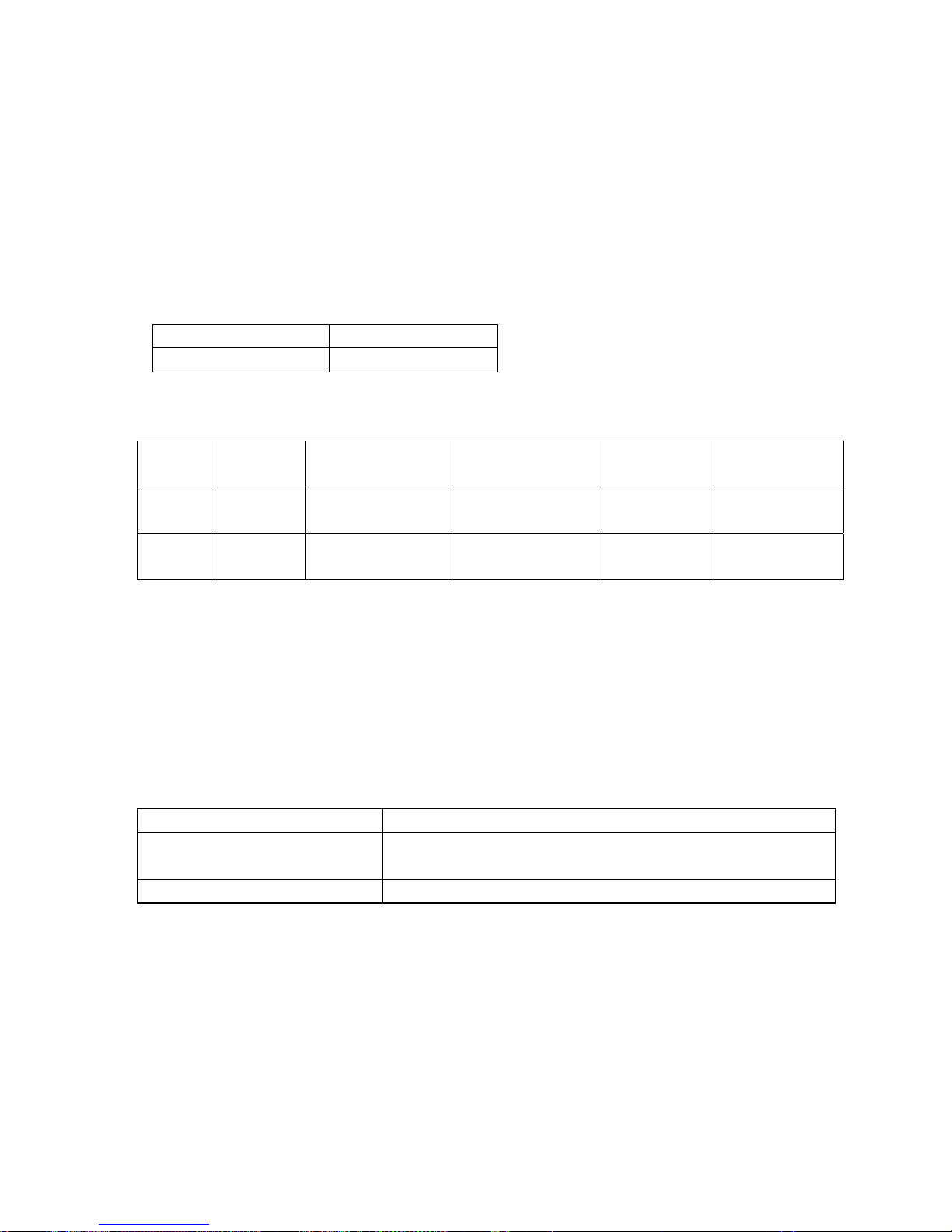
3.2 Outdoor frequency control
3.2.1 Compressor running frequency range: 20~90RPS
3.2.2 Definition of high-efficiency operation and its frequency control
In order to meet the cooling request at high ambient temperature and the heating request at low ambient
temperature, we set the high-efficiency operation.
Entering condition: cooling mode, Tao≥33℃(E), heating mode, Tao≤5℃(E).
3.3 Electronic expansion valve (EEV) control
3.3.1 Electronic characteristic
Max. open angle 500 pulse
Driving speed PPS
3.3.2 Initialization of EEV
EEV driving speed: open direction: 32MS; close direction: 32MS
3.3.3 Open angle limitation of EEV
Unit stop Adjustable upper
limitation
Thermostat ON Thermostat
OFF
Adjustable lower
limitation
Cool/Dry
5(E) 450(E)
Standard open
angle+tolerance
5(E) 80(E)
Heat
60(E) 450(E)
Standard open
angle+tolerance
60(E) 80(E)
3.3.4 Standard open angle control
In Cool/Dry mode, standard open angle: outdoor ambient temp.≥20℃, 250 pulse(E);
Outdoor ambient temp.<20℃, 210 pulse(E);
In Heat mode, standard open angle: outdoor ambient temp.≥10℃, pulse (E);
outdoor ambient temp.<10℃, 210 pulse (E).
3.3.5 When discharging temp. Td is too high, modify the EEV angle.
In order to cooperate the compressor discharging temp. over high protection, the system will enlarge the
EEV open angle. Within 5 minutes after compressor starts up, it will not modify. The detecting period is 30
seconds.
Cooling mode Indoor modification angle
100℃<discharging temp.
+50degree/30seconds, it will stop until up to the max. permitted
opening angle
90℃< discharging temp. £100℃
Keep the angle
-62-

£ 90℃
-5degree/30seconds, and reduce to 0 degree gradually
Heating mode Indoor modification angle
100℃< discharging temp.
+50degree/30seconds, it will stop until up to the max. permitted
opening angle
90℃< discharging temp. £100℃
Keep the angle
£90℃
-5degree/30seconds, and reduce to 0 degree gradually
3.4 4-way valve control in heating
Protection when 4-way valve can not reverse in heating:
10 minutes later after compressor startup, if indoor coil average temp. is below 15degree and keeps for 1
minute, the unit will stop and occur the 4-way valve protection.
Compressor ON
OFF
4-way valve ON
OFF
15s(E) 2minutes and 55s
3.5 Electric heater (crankcase) control
If compressor has not run for a long time, the refrigerant will deposit on the bottom of compressor and mix
with the refrigerant oil. When re-startup, because low pressure reduces, refrigerant will be segregated
from the refrigerant oil and cause soam in the oil, which will make compressor exhaust a lot of oil.
Therefore please stop heating the compressor bottom to ensure the low pressure in startup period should
not go down greatly.
Ambient temp. TA≤27degree, when compressor stops, the electric heater will be electrified.
When TA≥32degree, or compressor running, the electric heater will be off.
Heater ON
OFF
Ambient temp. TA(℃) 27 32
3.6 Control of liquid spray valve SV2:
According to the compressor discharging temp., open or close the SV2.
①Control condition:
A. In every mode (including defrosting and oil return operation), the control can work.
B. In 3 minutes after compressor startup, ignore the abnormal compressor suction and discharging value.
②3 minutes later after compressor startup, according to the discharging temp., the following procedure
will be taken:
Td≤90℃, SV2 close;
Td>110℃, SV2 open.
③In 150 seconds when compressor stops, in order to keep the system in balanc, please open the liquid
spray valve SV2. 150 seconds later after compressor stops, SV2 close.
3.7 Control of defrosting in heating
In heating mode, defrosting temp. sensor will check the frosting condition of outdoor heat exchanger and
make defrosting control.
3.7.1 Enter condition:
①In heating mode, if the compressor has run for 10 minutes continously and run for 45 minutes in all, the
system will measure the defrosting temperature sensor Te and outdoor ambient temp. sensor TA, if the
below condition can be met for continous 5 minutes, the unit will enter defrosting operation:
-63-

Te ≤C×TA-α
Herein: C:TA<0℃,C=0.8 TA≥0℃,C=0.6
According to SW2, the setting is as follow: in the place easy to frost, it is H; when out of factory, it is M.
Jumper
selection
M(out of factory) H
α(℃)
8(E) 6(E)
②Defrosting entering condition: -15℃≤C×TA-α≤-2℃
③Stop and Pause condition of compressor running accumulative time in heating mode:
Checking Stop: running operation changes from heating to cooling.
Checking Pause: thermostat OFF, or the unit stops.
3.7.2 Cancel condition:
It will take the max. 10 minutes from beginning defrosting to quit it. Te sensor will measure the condition of
outdoor heat exchanger, if the temp. is over 7℃ for 60 seconds in all or is up to 12℃ for 30 seconds in all,
the defrosting will be over.
3.7.3 Compulsory defrosting control
Enter condition: in heating mode, after receiving the compulsory defrosting signal from indoor unit, the unit
will perform the compulsory defrosting operation.
Cancel condition: Te≥12℃ and keep for 1 minute or the defrosting time is over 10 minutes.
The manual defrosting signal of indoor unit will remain until the outdoor enters defrosting mode.
Note: When outdoor compressor not running, the unti still can enter manual defrosting, but it will comply
with the 3-minute protection of compressor.
-64-

3.7.4 Defrosting operation flow chart
Beginning End
Fixed frequency Indicated FQY 60s Defrosting FQY 80 Hz(E) 60s Soft startup
compressor
0HZ 0HZ
5s
Outdoor motor ON Send defrosting signal to indoor Auto
OFF
4-way valve ON
OFF
ON
Spray valve SV2 OFF
450-pulse 450-pulse
350-pulse(E)
All EEVs Auto open angle Auto open angle
All indoor motors ON
OFF Anti-cold air function
-65-

3.8 Frequency control when Td is too high
Purpose: make compressor frequency control if the discharging temp. is too high, to lower the discharging
temp. efficiently and ensure the system can run normally.
3.9 Frequency control when there is CT over current protection
1.0 I
0.95I
0.93I
0.90I
0.88I
0.85I
Stop immediately, if abnormal stop 3 times in 1 hour, the
unit will stop and alarm.
Reduce FQY rapidly 2HZ/S
Reduce FQY rapidly 1HZ/S
Reduce FQY slowly 1HZ/10S
Remain FQY
Increase FQY slowly 1HZ/10S
Dischar
g
in
g
tem
p
. TD
If keeping for 10s, the unit stops, 3 minutes later, the unit can
re-startup. If in 60 minutes the unit occurs alarm for 3 times, the
failure can be eliminated.
Reduce FQY rapidly 2HZ/S
Reduce FQY rapidly 1HZ/S
Reduce FQY slowly 1HZ/10S
Remain FQY
Increase FQY slowly 1HZ/10S
120℃
115℃
110℃
105℃
100℃
95℃
-66-

3.10 High pressure protection
When the input signal of pressure switch is high level: 1, that shows there is no protection.
When the input signal of pressure switch is low level: 0 for 1 minute, that shows high pressure protection
works. At this time, compressor stops, outdoor will send the alarm signal. The alarm can be resumable. If
in 60 minutes, the failure occurs 3 times, the failure can be confirmed and send failure code to indoor.
Meanwhile, by controling the max. condensate temp. Tc (cooling) or TmAVE (heating), please confirm as
follow:
In nominal cooling/dry/heating mode, high pressure can be controlled by limiting the max. frequency.
3.11 Low pressure protection
(1) When compressor is running, if output signal of low pressure switch is low level: 0 for 1 minute
continously, compressor will stop, outdoor alarms. The alarm can be resumable. If in 60 minutes, the
failure occurs 3 times, the failure can be confirmed and send failure code to indoor.
(2) When compressor no running, if output signal of low pressure switch is low level: 0 for 30 seconds
continously, alarm will occur.
·When unit stops, the reason that system still checks the low pressure: in a long time stop, make
protection for the compressor on the condition of great refrigerant leakage.
·The reason that low pressure switch action time is 30 seconds: when compressor stops, low pressure
does not change, so it will be shorter than the set time in operation.
(3) When compressor starts up, in 8 minutes, low pressure switch signal will be shielded.
(4) In defrosting, low pressure switch will be shielded.
(5) In oil return procedure, low pressure switch will be shielded.
(6) In the refrigerant discharging procedure after the oil return in cooling is over, low pressure switch will
be shielded.
In addition, the system will control low pressure through the evaporator temp. TE to realize the low
pressure protection function.
Co
n
de
n
s
ing t
e
m
p
.
Keep for 5 seconds, stop to alarm, after 3-minute standby, the
unit can re-startup. In 3 minutes it occurs 3 times continously,
unit will stop to alarm and the failure can be resumed after being
electrified again.
Reduce FQY rapidly 2HZ/S
Reduce FQY rapidly 1HZ/S
Reduce FQY slowly 1HZ/10S
Remain FQY
Increase FQY slowly 1HZ/10S
70℃
68℃
66℃
64℃
62℃
60℃
-67-

In cooling, confirm through Tc2AVE:
In heating, confirm through defrosting temp. Te:
If the failure is not confirmed as the permanent protection, outdoor will not send failure code to indoor, and
indoor will not alarm.
TinAVE
-25℃
-30℃
-35℃
-40℃
-45℃
Normal operation
Min. running FQY 20HZ
SV2 OFF & 20HZ
SV2 ON & 20HZ
Keep for 5 seconds, unit stops and alarm
occurs. 3 minutes later, restart up. If i
t
occurs 3 times in 1 hour, it will always
alarm and stop, electrify again and failure
will be cleared.
Te
-30℃
-35℃
-40℃
-45℃
-50℃
Normal operation
Min. running FQY 20HZ
SV2 OFF & 20HZ
SV2 ON & 20HZ
Keep for 5 seconds, unit stops and
alarm occurs. 3 minutes later, restart
up. If it occurs 3 times in 1 hour, it will
always alarm and stop, electrify again
and failure will be cleared.
-68-

-69-
B) Indoor Unit Electrical Control Functions
1. Dip switch functions:
1.1 SW01 detailed definition is as following:
SW01
[1] [2] [3] [4] [5] [6] [7] [8]
Function
-- -- -- -- -
-- -- -- -- --
----
-- -- -- -- --
-- -- -- -- -- -- -- 0
Passive contact valid
-- -- -- -- -- -- -- 1
Passive contact invalid
-- -- -- -- -- -- 1 --
-- -- -- -- -- 0 -- --
AC 3-speed motor
-- -- -- -- -- 1 -- --
AC stepless motor
-- -- -- -- 0 -- -- --
Pre-set
-- -- -- -- 1 -- -- --
Pre-set
1.2 SW02 detailed definition is as following:
SW02
[1] [2] [3] [4] [5] [6] [7] [8]
Function
――
0 0 0 0 0 0 0
Central control address = 1
――
0 0 0 0 0 0 1
Central control address = 2
----
----
――
1 1 1 1 1 1 1
Central control address = 128
0
Setting of central control
address: ENABLED
1
Setting of central control
address: DISABLED
1.3 SW03 detailed definition is as following:
SW03
[1] [2] [3] [4] [5] [6] [7] [8]
-- -- -- -- --
-- -- -- -- --
-- -- -- -- --
-- -- -- -- --
-- -- -- -- --
-- -- -- -- --
-- -- -- -- --
-- -- -- -- --
-- -- -- 0 -- -- -- --
Infrared
remote control unit: YR-H71
-- -- -- 1 -- -- -- --
Wired control unit: YR-E12
-- -- -- -- 0 -- -- --
Display cooling only on YR-E12: (DRY, COOL, FAN)
-- -- -- -- 1 -- -- --
Display heat pump on YR-E12: (AUTO, HEAT...
Function
-- -- -- -- -- -- 0 --
To set indoor address(by
remote/wired controller)
To set indoor address
(by dip switches)

-70-
....DRY, COOL, FAN)
-- -- -- -- -- 0 0 0
Indoor communication address 1
-- -- -- -- -- 0 0 1
Indoor communication address 2
-- -- -- -- -- 0 1 0
Indoor communication address 3
-- -- -- -- -- 0 1 1
Indoor communication address 4
-- -- -- -- -- 1 0 0
Indoor communication address 5
-- -- -- -- -- 1 0 1
Indoor communication address 6
-- -- -- -- -- 1 1 0
Indoor communication address 7
-- -- -- -- -- 1 1 1
Indoor communication address 8
Note: “1” = dip switch at ON; “0”= dip switch at OFF.
2. Sign definition:
Indoor Outdoor
Tai Tc1 Tc2 Tm Tao Toci Tc Te Ts Td
Ambient
temp.
Outlet
pipe
temp.
Inlet
pipe
temp.
Mid
coil
temp.
Ambient
temp.
Thick pipe
of heat
exchanger
Mid
condenser
temp.
Defrost
temp.
Compressor
suction
temp.
Compressor
discharging
temp.
Tcomp 1, 2 Tset
Temp. compensation
Set
temp.
3. Dry operation
Tai<16℃, indoor unit stops running and sends stop-unit signal to outdoor.
Tai≤Tset, indoor motor runs at low speed and sends stop-unit signal to outdoor.
4. Fan operation
Indoor fan motor will run as the fan speed set on the remote controller or the wired controller and indoor unit
will send the stop-unit signal to outdoor.
5. Auto operation
5.1 If the unit enters Auto mode for the first time, the system will adjust the operation mode according to
the room temp. and the set temp.
When Tai≥Ts et, entering auto cooling mode;
When Tai<Ts et, entering auto heating mode.
5.2 Auto cooling mode is as the same as the cooling mode. After the thermostat is OFF for 15 minutes, if
Tai+ 1+Tcomp2<Tset, the unit will enter auto heating mode, or the unit will still stay at auto cooling mode
and stop when it reaches the set temperature; while the indoor motor will be at low speed.
5.3 Auto heating mode is as the same as the heating mode. After the thermostat is OFF for 15 minutes, if
Tai≥T set+1 +Tcomp1, the unit will enter auto cooling mode, or the unit will still stay at auto heating mode;
5.4 In this mode, the Sleep function is available, run as cooling sleep in cooling mode and as heating
sleep in heating mode. Once sleep mode is set, the mode will not change after the unit stops for 15
minutes when it arrives Tset.
5.5 Mode conversion will be confirmed after compressor has stopped for 10 minutes.
6. Abnormal operation
6.1 When outdoor modes from the request of indoor unit conflict, the one entering firstly will take priority.

-71-
6.2 After indoor receives the ON command from wired controller, it will firstly confirm the outdoor current
operation mode. If they are the same modes, indoor unit will run as the request of remote controller. If
they are different modes, the indoor units will be kept in standby mode until the previously operating units
will be in thermostat OFF condition. Then the initially stopped indoor units will be allowed to operate until
they will reach the thermostat OFF condition. And so on.
6.3 After indoor receives the ON command from r emote controller, it will firstly confirm the outdoor current
operation mode. If they are the same mode, indoor unit will run as the request of remote controller. If they
are different modes, the indoor units will be kept in standby mode until the previously operating units will be
in thermostat OFF condition. Then the initially stopped indoor units will be allowed to operate until they will
reach the thermostat OFF condition. And so on. With abnormal operation the buzzer sounds twice.
6.4 In AUTO mode, when the indoor unit occurs abnormal operation, the indoor unit will keep OFF state,
and the buzzer will not sound until the outdoor mode and the requested mode of indoor unit are the same.
6.5 COOL (included AUTO COOL), DRY, FAN are not abnormal mode.
6.6 HEAT and FAN are not abnormal mode.
7. Control for discontinuous operation
After the unit starts up in cooling/heating mode, in 5 minutes, the compressor run/stop will not be
controlled by the room temp., but after changing the set temp., if compressor stop condition can be met,
the system will stop compressor immediately.
8. Anti-cold air control
In heating mode, after compressor startup, the system will control indoor fan motor according to indoor
coil temperature. Detailed operation is as below:
Tc2(°C)
30(32)
Set speed
26(30) Low speed
22(26) Off
20(20)
Note:
1) The data in the parentheses is the control point when Tao>10℃;
2) Indoor unit will send “pre-heat” signal to wired controller in anti-cold air period.
9. Fan motor control in defrosting
9.1 On receiving outdoor defrosting signal, indoor unit will stop after blowing remaining heat at slow
speed for 20 seconds.
9.2 In defrosting period, indoor fan motor stops running.
9.3 Defrosting is over, and indoor motor will run as anti-cold air state.
10. Blowing remaining heat operation
When the unit shuts off in heating mode or the thermostat is OFF, indoor motor will stop running after
running at low speed for 30 seconds.
11. Swing motor control
Indoor unit will control the swing motor according to the swing signal from the wired/wireless controller.

Full OFF 54º
12. Water pump control (this device is not present on HSFL XMR Indoor Units)
12.1 Water pump will be electrified when indoor unit enters non-heating mode until indoor unit stops. 5
minutes later after indoor unit stops, water pump will stop.
12.2 When indoor unit is in heating mode, water pump will not operate.
12.3 In OFF state and in any mode, once float switch signal is measured, indoor unit will send OFF signal
to outdoor and send the failure code of drainage system to the wired controller, then the water pump will
work until the float switch signal is cancelled. After water pump is forced to run for 5 minutes, indoor unit
will be back to normal state.
13. Compulsory defrosting operation
13.1 After indoor receives the compulsory defrosting signal, it will send continously the signal to outdoor
for 10 times, in this period, indoor unit will work normally and it will enter defrosting operation until it
receives the enter-defrost signal from outdoor unit.
13.2 Wired control type: In heating mode, make a jumper for D2 to enter compulsory defrosting.
13.3 Remote control type: In heating mode, high speed, 30°C, press SLEEP button 6 times, and the
buzzer will sound 3 times, then enter the manual defrosting.
14. Trial operation
14.1 Enter condition
A. Wired control type: In OFF state of COOL or HEAT mode, press ON/OFF button for over 5 seconds to
enter the cooling or heating trial operation;
B. Remote control type: In OFF state, keep pressing ON/OFF button until 5 seconds later, the buzzer
sounds twice, then enter the cooling or heating trial operation;
14.2 Response in trial operation
A. Cooling trial operation: indoor sends S-CODE=SD to outdoor, indoor: at high speed, set temp: 16°C;
B. Heating trial operation: indoor sends S-CODE=SF to outdoor, indoor: at high speed, set temp: 30°C;
C. In this period, anti-freezed and overheat functions are invalid.
14.3 Quit condition
A. Receiving the signal of cancelling trial operation from wired controller or remote controller;
B. After trial operation has run for 20 minutes, it will quit trial operation automatically and enter the
normal mode with the set temp.: 24°C.
15. Timer operation
15.1 Wired control type: wired controller will control the unit ON/OFF;
15.2 Remote control type: indoor unit will confirm the unit ON or OFF according to the current clock and
the timer clock set by remote controller. When setting timer function, the timer LED will be ON.
16. SLEEP function (not available on YR-E12 wired controller)
16.1 Wired control type unit is without sleep function;
16.2 Remote control type unit consists of cooling sleep and heating sleep, after the sleep is set, the unit
0°
Standard position in
HEAT, COOL mode
Swing range
54°
-72-

will change mode; the sleep will begin to count.
A. In cooling/dry mode, after running for 1 hour, the set temp. will increase 1°C, another 1 hour later, the
set temp. will increase 1°C again, then 6 hours (or set time-2) later , it will stop.
B. In heating mode, after running for 1 hour, the set temp. will reduce 2°C, another 1 hour later, the set
temp. will reduce 2°C again, then 3 hours later, the set temp. will increase 1°C, and another 3
hours (or set time-5), it will stop.
C. When setting sleep function, indoor motor is forced at low speed.
17. Healthy negative ion function (not available on HSFL XMR Indoor Units)
When receiving the healthy signal from the wired controller or remote controller, if fan motor is running,
the negative ion will work;
If the fan motor stops, the negative ion generator will stop.
18. Auto-restart function
18.1 Wired control type: jumper J07 at high level, auto-restart is available, if at low level, auto-restart is
cancelled; when out of factory, the unit is with auto-restart function.
18.2 Remote control type: In 5 seconds, press SLEEP button (press SWING if without SLEEP button) 10
times continuously, the buzzer will sound 4 times and enter auto-restart function. In 5 seconds, press
SLEEP 10 times continuously, the buzzer will sound twice and quit auto-restart function.
18.3 Memory information: ON/OFF state, mode, fan speed, set temp., health, swing position;
18.4 If the memory includes timer or sleep function, when being electrified again, timer and sleep will be
cancelled;
18.5 If the memory includes auto mode, when the jumper shows cooling only type, auto mode will change
to cooling mode.
19. Passive contact function
The unit adopts passive contact (220VAC input), which only make ON/OFF control. When it is close, the
unit is ON; when it is open, the unit is OFF, and the other parameters will be as default or the data in
memory.
19.1 Passive contact valid
The central control, remote control/wired control and the passive contact are “AND” relationship. The unit
must be switched on by remote controller or wired controller; meanwhile the passive contact is close,
indoor unit is ON and runs at the set state by the central controller, remote controller or wired controller;
19.2 Passive contact invalid
The central control, remote control/wired control and the passive contact are “OR” relationship. As long as
the unit is switched on by remote controller or wired controller; meanwhile the passive contact is close,
indoor unit is ON and runs at the set state by the central controller, remote controller or wired controller;
when being electrified for the first time, and there is no auto-restart function, the passive contact is close,
the unit will run in the following condition: cooling mode, auto fan speed, set temp. 24°C.
20. Data readout program (YR-E12) / Setting indoor unit number (YR-H71)
A. Wired control unit
At first, check the current indoor address:
In normal state, press SET button on wired controller for 5 seconds, the temp. setting area in LCD will
display [XX], XX is indoor unit number, and you can select the number by temp. increasing/reducing
button. And the timer setting area in LCD will display [YZZZ], Y is the digit type, ZZZ is the corresponding
data. You can select the data by temp. increasing/reducing button.
-73-

Y ZZZ Digit type
A Temp. of indoor sensor Tai Actual data, decimal
b Temp. of indoor sensor Tc1 Actual data, decimal
C Temp. of indoor sensor Tc2 Actual data, decimal
d Opening angle/2 of indoor EEV Actual data, decimal
E Indoor address Actual data, hex
F Indoor central address Actual data, hex
B. Remote control type:
1) Enter method
In OFF state, press emergency switch until 15 seconds later, the buzzer sounds 4 times, indoor will enter
the indoor unit number setting state.
2) Setting method
Press ON/OFF button (from OFF mode to ON mode), the times of SLEEP button to be pressed is the set
unit number, then press ON/OFF button to quit unit number setting state, at this time, indoor unit is at OFF
state, the display panel will display this unit number. For example, press SLEEP button once, it is No. 1
unit; press twice, it is No. 2 unit, and so on.
3) Quit method
In OFF state, press emergency switch until 15 seconds later, the buzzer sounds 5 times, the display
panel will display this unit number and you can check if there are repeated numbers.
21. Setting method of temperature compensation Tcomp
A. On wired control type unit YR-E12, this function is not available.
B. Remote control type unit:
In cooling or heating mode, there is always with the temp. compensation.
In heating mode: In 24°C heating mode, press SLEEP (or SWING) button 7 times continuously within 5
seconds, indoor buzzer sounds twice, that shows temp. compensation works. Switch on the unit in
heating mode by the remote controller, press TEMP button to set the set temp., so temperature
compensation=the current set temp. - 24°C. For example, if the set temp. is 24°C, the temp.
compensation is 0°C; if the set temp. is 25°C, the temp. compensation is 1°C. The max. compensation
temp. is 6°C (the set temp. is 30°C). If you want to cancel it, set the temp. as 24°C.
In cooling mode: In 24°C cooling mode, press SLEEP (or SWING) button 7 times continuously within 5
seconds, indoor buzzer sounds twice, that shows temp. compensation works. Switch on the unit in
heating mode by the remote controller, press TEMP button to set the set temp., so temperature
compensation=24°C - the current set temperature . For example, if the set temperature is 24°C, the temp.
compensation is 0°C; if the set temp. is 23°C, the temp. compensation is -1°C. The max. compensation
temp. is -8°C (the set temp. is 16°C). If you want to cancel it, set the temp. as 24°C.
So the temp. compensation range is +8°C - 6°C.
22. Anti-freezed protection
When compressor has run for over 5 minutes, to prevent indoor evaporator freezing (in cooling/dry mode),
if indoor mid-coil temp. is below -1 degree for over 5 minutes, indoor EEV will close, and compressor will
stop. When indoor mid-coil temp. is over about 10 degrees, the unit will be normal.
23. Overload protection in heating mode
It is valid only in heating mode, if indoor mid-coil temp. is over about 65 degrees continuously for 10
seconds, indoor will stop; while when indoor mid-coil temp. is below 52 degrees for 3 seconds, indoor will
resume.
-74-

11. Diagnostic information (troubleshooting)
Okpa=
41Qha]oa_kjp]_ppdaejop]hhanokn`eopne^qpknopknal]enepsdajpnkq^had]llajo1
51Uqnjpdalksankbb]j`lksankj]c]ej/ebpdab]ehqna_k`ana_qno/lha]oaejbknifrompda`eopne^qpkn1
61Failure codes marked with are resumable.
B^jkni]h_kiiqje_]pekj
^apsaajsena`_kjpnkhhar
and ej`kknqjepQDC
9UJNFT
B^jkni]h_kiiqje_]pekj
^apsaaj_delUNQ2;3:
]j`_delUNQ2;79
47UJNFTG]qhpuej`kknqjepQDC
Failure codes on the indoor Unit when using YR-H71 infrared remote controller:
FAILURE DESCRIPTION
NUMBER OF FLASHINGS OF
THE TIMER LAMP ON THE
INDOOR UNIT LED PANEL
vuxxpirlwlhxutx
G]qhpupailan]pqnaoajokny}0
PODF
Tajokn`eo_kjja_pa`/kn^nkgaj/kn]psnkjc
lkoepekj/knin odknp_en_qep
G]qhpupailan]pqnaoajokny*e
Tajokn`eo_kjja_pa`/kn^nkgaj/kn]psnkjc
lkoepekj/knin odknp_en_qep
G]qhpupailan]pqnaoajokny*f
6UJNFT
Tajokn`eo_kjja_pa`/kn^nkgaj/kn]psnkjc
lkoepekj/knin odknp_en_qep
G]qhpu pailan]pqna oajokn y3 7 UJNFT
Tajokn `eo_kjja_pa`/ kn ^nkgaj/ kn ]p snkjc
lkoepekj/knin odknp_en_qep
G]qhpu FFQSPN kj ej`kkn
qjep QDC
8 UJNFT G]qhpu ej`kkn qjep QDC
B^jkni]h_kiiqje_]pekj
^apsaajej`kkn/kqp`kknqjep
Xnkjc_kjja_pekj/knsenaoare `eo_kjja_pa`/
knsnkjc]``naoooappejckbej`kknqjepo/
or faulty lksanoqllhuknb]qhpuQDC
Jj`kkn qjep ]``naoo nala]pa`
< UJNFT
Xnkjc oappejc kb ej`kkn qjep ]``naoo
N]hbqj_pekjkjkqp`kknqjep53UJNFTDda_g pdakqp`kknqjepb]ehqna_k`a
UXJDF
:UJNFT
Xnkjc_kjja_pekj/knpdasena`_kjpnkhhan
wires are `eo_kjja_pa`/or b]qhpuQDC
-75-

-76-
06
FAILURE CODES
(CHECK ON THE WIRED
REMOTE CONTROLLER)
TROUBLE SHOOTING
(Indoor Unit)
Failure codes (related to Indoor Unit) on the wired remote controller YR-E12
Abnormal communication
between wired controller and
indoor unit PCB
*
*
*
*
*
*
POSSIBLE REASONS
Faulty temperature sensor Tai
01
Sensor disconnected, or broken, or at wrong
position, or short circuit
Faulty temperature sensor Tc1
Sensor disconnected, or broken, or at wrong
position, or short circuit
Faulty temperature sensor Tc2
03
Sensor disconnected, or broken, or at wrong
position, or short circuit
Faulty temperature sensor Tm 04
Sensor disconnected, or broken, or at wrong
position, or short circuit
Faulty EEPROM on indoor
unit PCB
05
Faulty indoor unit PCB
Abnormal communication
between indoor and outdoor unit
Wrong connection, or the wires are
disconnected, or wrong address setting of
indoor units, or faulty power supply or faulty
PCB
02
Abnormal communication
between chip TMP/807 and chip
TMP/846
0E
Faulty indoor unit PCB
Indoor unit address repeated
09
Wrong setting of indoor unit address
07
Wrong connection, or use the wired controller
when disconnected, faulty PCB
(* shows the failure is resumable)

-77-
TROUBLE SHOOTING
(Outdoor unit)
FAILURE CODES
(CHECK ON THE WIRED
REMOTE CONTROLLER)
Faulty defrost sensor Te
Sensor disconnected, or broken, or short circuit
Faulty sensor Tao Sensor disconnected, or broken, or short circuit
Faulty sensor Ts Sensor disconnected, or broken, or short circuit
Faulty sensor Td
Sensor disconnected, or broken, or short circuit
Input overcurrent
Over current of the system, or broken of the
current sensor, or malfunction of indoor or
outdoor fan motors, or faulty PCB.
15
16
17
14
19
System high pressure
protection
High pressure switch is disconnected, or high
pressure switch worked, or Tc too high and
faulty outdoor fan motor when cooling, or
faulty indoor fan motors when heating, or
refrigerant excessive charge
1E
System low pressure
protection
Low pressure switch is disconnected, or low
pressure switch worked, or Te too low and
faulty outdoor fan motors when heating, or
faulty indoor fan motor when cooling, or
refrigerant shortage
1F
IPM protection
IPM over current, or short circuit, or
IPM temperature is too high, or IPM input
voltage too low, or faulty SPDU (or ISPM).
EEPROM fault
Faulty outdoor unit PCB
20
21
Overheat protection of
compressor
Serious lack of refrigerant of the system, or too
high ambient temperature, or PMVs is blocked
22
Over heat protection of SPDU
(or ISPM)
Ambient temperature too high, or outdoor fan is
blocked, or bad air circulation on outdoor unit
23
DC fan motor fault
Fan is blocked, or the terminal is disconnected from
the PCB
24
POSSIBLE REASONS
Faulty 4-way valve
switching on
Coil of 4-way valve is disconnected, or faulty
outdoor PCB
25
Faulty sensor Tc
Sensor disconnected, or broken, or short circuit
26
Faulty sensor Toci
Sensor disconnected, or broken, or short circuit
2A
Low voltage protection
VDC<194V, too low voltage from power source
High voltage protection
VDC>400V, too high voltage from power source
2C
2D
Abnormal communication
between main PCB and
SPDU (or ISPM)
2E
Compressor is locked Faulty compressor or SPDU (or ISPM)
Excessive compressor vibration
Faulty compressor
Compressor lose position
Faulty SPDU (or ISPM)
Faulty compressor start
Faulty compressor or SPDU (or ISPM)
Faulty position checking
circuit
Faulty SPDU (or ISPM)
Compressor breakdown
Faulty compressor or SPDU (or ISPM)
32
33
34
35
37
38
Communication cables broken, or bad connection,
or faulty main PCB, or faulty SPDU (or ISPM)
Failure codes (related to Outdoor Unit) on the wired remote controller YR-E12

-78-
HCNL 821 XMR Outdoor Unit error codes
FAILURE
CODE
STATE OF
LED 5-4-3-2-1
TROUBLE
SHOOTING
POSSIBLE REASONS
DC fan motor fault
Fan is blocked, or the terminal is disconnected
from the PCB
Faulty 4-way valve
switching on
Coil of 4-way valve is disconnected, or faulty
outdoor PCB
Abnormal communication
between main PCB and
SPDU(or ISPM)
Communication cables broken, or not be well
connected, or faulty main PCB, or faulty SPDU(or
ISPM)
Compressor be locked Faulty compressor or SPDU(or ISPM)
Compressor vibration too big
Faulty compressor
Compressor lose position Faulty SPDU(or ISPM)
Faulty compressor start Faulty compressor or SPDU(or ISPM)
Faulty position checking
circuit
Faulty SPDU(or ISPM)
Compressor broken Faulty compressor or SPDU(or ISPM)
15
16
25
26
27
28
29
30
31
1 Faulty defrost sensor Te Sensor disconnected, or broken, or short circuit
Faulty sensor Tao Sensor disconnected, or broken, or short circuit2
Faulty sensor Ts Sensor disconnected, or broken, or short circuit3
Faulty sensor Td Sensor disconnected, or broken, or short circuit4
Input overcurrent
Over current of the system, or broken of the current
sensor,or malfunction with indoor or outdoor fan
motors, or faulty PCB.
5
Abnormal communication
between indoor and outdoor
units
Wrong connection, or the wires be disconnected, or
wrong address setting of indoor units, or faulty
PCB, or faulty power supply
6
System high pressure
protection
High pressure switch is disconnected, or high
pressure switch worked, or Tc too high and faulty
outdoor fan motor when cooling, or faulty indoor
fan motors when heating, or refrigerant
overabundance
9
System low pressure
protection
Low pressure switch is disconnected, or low
pressure switch worked, or Te too low and faulty
outdoor fan motors when heating, or faulty indoor
fan motor when cooling, or refrigerant shortage
10
IPM protection
IPM over current, or short circuit, or IPM
temperature too high, or IPM input voltage too
low,or faulty SPDU(or ISPM).
11
EEPROM fault Faulty outdoor unit PCB12
Over hot protection of
compressor
Serious lack of refrigerant of the system, or the
ambient temperature too high, or PMVs be
blocked
13
Over hot protection of SPDU
(or ISPM)
Ambient tempreatrue too high, or outdoor fan be
blocked, or bad air circulation of outdoor unit
14
Faulty sensor Tc Sensor disconnected, or broken, or short circuit17
Faulty sensor Toci Sensor disconnected, or broken, or short circuit21
Low voltage protection VDC<194V, too low voltage from power source23
24
High voltage protection
VDC>400V, too high voltage from power source
Take of f the plastic cover on the right side of the unit, you can find the LEDs near the communication terminal.
Symbol means the LED is ON, and symbol means the LED is OFF.

Troubleshooting:
Replace the fuse
and check again
Replace power
wiring and
check again
Display panel
circuit is damaged,
replace it
PCB is faulty,
replace it
Check if fuse is
burnt
YES
YES
YES
Check if power
wiring is in open
circuit
NO
NO
NO
Check if display
panel has 12V
power supply
PCB is faulty,
replace it
Check the terminal
power supply
If the power
terminal block has
220V input
YES
YES
If the red diode
and green diode
on indoor PCB
flash in turn
Replace display
panel and check
again
yes
NO
NO
Check if display
panel and the
unit matched
well
Trouble 1: No display on the operation panel
NO
Start
PCB is faulty
and replace it,
check again
Replace
sensor and
check again
Replace sensor
and check again
Check if sensor
resistor value is
correct
NONO
YES
YES
yes
Check if sensor is in
open circuit or PCB
port is not in good
condition
Re-fix the sensor
and check again
As per the wiring
diagram, check the
connection
between sensor
and PCB is correct
Trouble 2: Sensor failure
NO
Start
-79-

Adjust the
distance and
check again
Replace the
communication
connection wire,
then check again
PCB is faulty,
replace it and
check again
If the power cable and the
communication wire are
too close, resulting in the
wrong data transmission
Check if the
communication port
connecting to the
indoor/outdoor PCB is
in open circuit
Re-wiring, and
check again
NO
NO
YES
YES
YES
As per the wiring
diagram, check if
communication
wiring is correct
Start
Trouble 3: Communication failure between indoor and outdoor
NO
Replace fan motor
feedback port, cut off
power supply and be
electrified again
Replace fan motor
input port, cut off
power supply and
electrify again
PCB is faulty,
replace it
Check the fan motor
feedback wire is
fixed badly (CN7
on PCB)
YES
YES
NO
NO
Check if the fan
motor input
connection is fixed
badly (CN7 on PCB)
Trouble 6: Indoor fan motor failure, AC fan motor has not 50Hz zero-crossing detection
Trouble 5: Indoor repeated unit number. If the infrared remote controller YR-H71 is present, proceed as follows.
Trouble 4: Indoor PCB EEPROM data is wrong
1.If the failure occurs when electrifying for the first time, that shows EEPROM
(8-bit pin) is not fixed firmly or it is
damaged.
2.If the failure occurs when running, that shows EEPROM is faulty and needs to be replaced.
1.Firstly query the unit number: switch off the unit, press SLEEP for about 20 seconds until the buzzer sounds 5 times,
The Timer lamp on the panel of the unit will flash according to the address number. By this method, you can check if
there is repeated unit number, if yes, please re-set the number as per the unit number setting procedure.
2.Re-set the unit number directly, the unit with outdoor pipe A is No. 1; the unit with outdoor pipe B is No. 2; the unit
with pipe C is No.3; the unit with outdoor pipe D is No. 4.
Start
-80-

Is the power supply transformer
component in good condition?
YES
Check if wiring
is correct
Check if failure disappears after
changing transformer or PCB
NO
NO
Check if failure disappears after
changing wired controller
YES
Wired controller
is broken
Trouble 7: Communication failure between wired controller and indoor PCB or no display on wired controller
Confirm communication failure
according to the fault code list
or no display
YES
YES
For some models, when powered on, during
initialization will display "88", if initialization
cannot finish, check indoor dip switch position
no
Is voltage between A and
B of wired controller 12V?
YES YES
YES
Is voltage between B
and C fluctuating?
Replace PCB
no
NO
NO
Check if the wired controller
can match with indoor PCB
Replace wired controller
NO
Is power just turned on?
Check if the dip
switch position
on PCB is right
Correct the position
-81-

Followings are not problems
Sound of water flowing is
not a problem.
Sound of cracking is heard.
Smell are generated.
During operation, white fog or steam
comes out from the indoor unit.
No outlet air or fan speed can't be changed
in dry mode.
In cooling operation, unit switches to
blowing operation.
Won't start?
In heating operation, water or steam are
blown out of outdoor unit.
In heating operation, indoor fan won't stop
even if unit is stopped.
During unit operation or at stop, a swishing or
gurgling noise may be heard. This noise is generated
by refrigerant flowing in the system.
Unit will not restart after stop.
During unit operation, a cracking noise may be heard.
This noise is generated by the casing expanding or
shrinking because of temperature changes.
This is because the system circulates smells from the
interior air such as the smell of cigarettes or the
painting on the furniture.
When unit is running at places like restaurant, etc. where
dense edible oil fumes always exist, this will happen.
To prevent frost from accumulating on indoor heat
exchanger, unit will switch to blowing operation for a
while then resume cooling operation.
Though ON/OFF button is set
to ON, unit won't resume cooling,
dry or heating operation
in 3 min after it is stopped, this
is because of 3-min-delay
protection circuit.
Please wait 3 minutes
Unit will reduce fan speed repeatedly and automatically
if room temp. is too low in dry operation.
This occurs when frost accumulated on the outdoor
unit is removed.
(during defrosting operation)
After unit stop, indoor fan will go on running
until indoor unit cools down.
Apparent abnormalities
-82-

Before ask for services, please first check your unit against the following.
Air conditioner won't start.
Poor cooling or heating
Is power supply switch
turned on?
Power supply
switch is not
set at ON.
Is city power supply normal? Is leakage current breaker
activated?
This is very dangerous, please
disconnect power supply
immediately and contact your
dealer.
Are operation control
adjusted correctly
as specified?
Is air filter too dirty?
Are there any obstacles in inlet
or outlet grill?
Are horizontal louvers at
up position (in heating
mode)?
Any doors or windows left
open?
Is there any direct sunlight
in the room?
If there are unexpected heat
sources in the room?
Too many people in the room?
Poor cooling
Is air conditioner in standby
condition in heating mode?
Cold air blows out
(in heating mode)
If your unit still can't work properly after above mentioned
checks, or following problems occur, please stop it immediately
and contact your dealer.
Fuses or circuit breakers often blow out.
W ater comes out in cooling/dry operation.
Operation is abnormal or sound is heard.
Power
failure?
Proper
temp
Apparent abnormalities
-83-

12. Electrical data
12.1 Wiring diagram
HCNL 821 XMR Outdoor Unit:
N
L
M
CN17
TD
TE
TS
TA
TC
CN16 CN15
LED2
LED1
CN12
CN11
CRANKCASE
HEATER
CN10
CN9
Y/G
4-WAY
VALVE
AC FAN MOTOR
W
U
COMPRESSOR
V
CN1
220VAC-N
C2C1
T25A 250VAC
FUSE
LED5
LED3
LED4
LED1
LED2
M
CN21
250VAC T3.15A
SW5
TD: COMPRESSOR DISCHARGING TEMP. SENSOR
SW5
To Power Supply
CN26
FUSE1
TS: COMPRESSOR SUCTION TEMP. SENSOR
TC
CONDENSING TEMPERATURE SENSOR
TE DEFROSTING TEMPERATURE SENSOR
TA AMBIENT TEMPERATURE SENSOR
TOCI
TOCII: PIPING TEMPERATURE SENSOR
MM
CN4
NLM
CN22
CN18
PMV_B
PMV_C
PMV_D
PMV_A
SV2
CN6
ON
12345678
PTC
BUS
L
CN8
N
ON
4321
SW3 SW4
SW2SW1
start/up s top/down
B : BLACK
R : RED
OR : ORANGE
W : WHITE
Y/G : YELLOW/GREEN
CN19
LPHP
CN20
CN23
H
CN3
CN5
CN14 CN13
CN1
CN2
CN7
LED
DEBUG_LED
4WV
CN2
CN5
CONTROL
BOARD
CN4
CN3
220VAC-L
CN8
CN7
CIRCUIT
BOARD
POWER
RL1
UVW
R
T/RB
S
T/RB
N(-)
P(+)
+-
ISPM
Y/G
WB
ORBL
BL : BLUE
CAPACITOR
REACTOR
M
TO ISPM
RBR
BR:BROWN
UNLOADING
VALVE
CAPACITOR
ISPM: INVERTER SYSTEM POWER MODULE
-84-

12.2 Circuit diagram
Outdoor Unit HCNL 821 XMR: PCB layout
-85-

-86-
12..3 Wiring diagram
Indoor Units: H
SFL 411, 531 XMR
W
CN12
W
Please plug in the short-connector to CN16
W
R
CN16
CN19
BL
W
CN26CN15
Y
SW01
SW02
SW03
ON
1
2
3
4
5
6
7
8
8
7
6
5
4
3
2
1
1
2
3
4
5
6
7
8
ON
ON
7P
7&
TRANSFORMER
W
CN14
CN24
OR
Y
BL
R
BR
BLBR
SW03-2 SW03-3
ON
SW03-1
SW03-1
ON
SW03-3SW03-2
SW03-2 SW03-3
ON
SW03-1
SW03-3SW03-2SW03-1
ON
14000
BTU
18000
BTU
12000
BTU
9000
BTU
SW03-4
ON
ON/OFF
CARD
ON
SW03-4
INFRARED
CONTROLLER
WIRED
CONTROLLER
CN12
Please pull out the short-connector from
CN16 (default set from factory)
The short
-connector is in the accessories.
WIRED
CONTROLLER
B: BLACK
BR: BROWN
R: RED
W : WHITE
Y/G : YELLOW/GREEN
BL:BLUE
Y:YELLOW
OR
˖ORANGE
TO
OUTDOOR
UNIT
C
AB
Q
P
LED
7&
AMBIENT
TEMPERATURE
SENSOR
W
CN10
B
CN13
R
CN22
G
W
CN19
CN7
TO OUTDOOR
UNIT
Y/G
N
L
Y/G
capacitor
2uF 450V
AC FAN MOTOR
M
FUSE1
T3.15A
250VAC
CN2
CN1

12.4 PCB Photo
Indoor Units: HSFL 411, 531 XMR
CN20
Lamp 3,4
CN1
CN3
CN21
CN6
CN5
CN4
CN12
SW2
CN7
SW3
CN15
CN26
Lamp 1,2
CN22
SW1
CN8
CN24CN10 CN14 CN13
CN2
-87-

-88-
12.5 Sensors' description and their resistance values
Models Name Characteristics of temperature/resistance
R25=10KΩ±3%
B25/50=3700K±3%
R25=23KΩ±2.5%
B25/50=3700K±3%
Discharging temp. sensor
R80=50KΩ±3%
B25/80=4450K±3%
Mid-condenser temperature sensor
R25=10KΩ±3%
B25/50=3700K±3%
Outdoor ambient temp. sensor
R25=10KΩ±3%
B25/50=3700K±3%
HTFL 261 XMR
HTFL 351 XMR
HTFL 411 XMR
HCNL 821 XMR
R25=10KΩ±3%
B25/50=3700K±3%
R25=23KΩ±2.5%
B25/50=4200K±3%

T(℃)
Rnom(KΩ)
T(℃)
Rnom(KΩ)
T(℃)
Rnom(KΩ)
T(℃)
Rnom(KΩ)
T(℃)
Rnom(KΩ)
-20℃
281.34
24℃
24.12
-20℃
90.79 24 10.43 68 2.09
-19℃
263.56
25℃
23 -19 85.72 25 10 69 2.03
-18℃
247.04
26℃
21.94 -18 80.96 26 9.59 70 1.96
-17℃
231.66
27℃
20.94 -17 76.51 27 9.21 71 1.9
-16℃
217.35
28℃
19.99 -16 72.33 28 8.84 72 1.85
-15℃
204.02
29℃
19.09 -15 68.41 29 8.48 73 1.79
-14℃
191.61
30℃
18.23 -14 64.73 30 8.15 74 1.73
-13℃
180.04
31℃
17.42 -13 61.27 31 7.83 75 1.68
-12℃
169.24
32℃
16.65 -12 58.02 32 7.52 76 1.63
-11℃
159.17
33℃
15.92 -11 54.97 33 7.23 77 1.58
-10℃
149.77
34℃
15.22 -10 52.1 34 6.95 78 1.54
-9℃
140.99
35℃
14.56 -9 49.4 35 6.68 79 1.49
-8℃
132.78
36℃
13.93 -8 46.86 36 5.43 80 1.45
-7℃
125.11
37℃
13.34 -7 44.46 37 5.6
-6℃
117.93
38℃
12.77 -6 42.21 38 5.59
-5℃
111.22
39℃
12.23 -5 40.08 39 5.73
-4℃
104.93
40℃
11.71 -4 38.08 40 5.52
-3℃
99.04
41℃
11.22 -3 36.19 41 5.32
-2℃
93.52
42℃
10.76 -2 34.41 42 5.12
-1℃
88.35
43℃
10.31 -1 32.73 43 4.93
0℃
83.5
44℃
9.89 0 31.14 44 4.9
1℃
78.94
45℃
9.49 1 29.64 45 4.58
2℃
74.67
46℃
9.1 2 28.22 46 4.42
3℃
70.65
47℃
8.74 3 26.4 47 4.26
4℃
66.88
48℃
8.39 4 25.61 48 4.11
5℃
63.33
49℃
8.05 5 24.41 49 3.97
6℃
60
50℃
7.73 6 23.27 50 3.83
7℃
56.86
51℃
7.43 7 22.2 51 3.7
8℃
53.91
52℃
7.14 8 21.18 52 3.57
9℃
51.13
53℃
6.86 9 20.21 53 3.45
10℃
48.51
54℃
6.6 10 19.3 54 3.33
11℃
46.04
55℃
6.34 11 18.43 55 3.22
12℃
43.72
56℃
6.1 12 17.61 56 3.11
13℃
41.52
57℃
5.87 13 16.83 57 3.11
14℃
39.45
58℃
5.65 14 16.09 58 2.9
15℃
37.5
59℃
5.44 15 15.38 59 2.81
16℃
35.66
60℃
5.24 16 14.71 60 2.72
17℃
33.92 17 14.08 61 2.63
18℃
32.27 18 13.48 62 2.54
19℃
30.72 19 12.9 63 2.49
20℃
29.25 20 12.36 64 2.38
21℃
27.86 21 11.84 65 2.3
22℃
26.54 22 11.34 66 2.23
23℃
25.3 23 10.87 67 2.16
R25=10KΩ±3%
B25/50=3700K±3%
R25=23KΩ±2.5%
B25/50=4200K±3%
R25=10KΩ±3%
B25/50=3700K±3%
R25=23KΩ±2.5%
B25/50=4200K±3%
R25=10KΩ±3%
B25/50=3700K±3%
-89-

Annual
Unit A Unit B Unit C Unit D MIN STD MAX
201
531
2,00
5,00——
1,00
7,00
8,00
0,55
2,75
3,80
2,55
1375
2,50
12,20
16,80
261
531
2,50
5,00——
1,00
7,50
8,00
0,55
2,75
3,80
2,73
1375
2,50
12,20
16,80
351
411
3,20
4,10——
1,00
7,30
8,00
0,55
2,75
3,80
2,65
1375
2,50
12,20
16,80
351
531
3,05
4,95——
1,00
8,00
8,50
0,55
2,75
3,80
2,91
1375
2,50
12,20
16,80
411
411
4,00
4,00——
1,00
8,00
8,20
0,55
2,75
3,80
2,91
1375
2,50
12,20
16,80
411
531
3,52
4,48——
1,00
8,00
9,00
0,55
2,75
3,80
2,91
1375
2,50
12,20
16,80
531
531
4,00
4,00——
1,00
8,00
9,50
0,55
2,75
3,80
2,91
1375
2,50
12,20
16,80
201
201
351
2,00
2,00
3,50
—
1,50
7,50
8,50
0,55
2,70
3,80
2,78
1350
2,50
11,98
16,80
201
201
411
2,00
2,00
4,00
—
1,50
8,00
8,50
0,55
2,70
3,80
2,96
1350
2,50
11,98
16,80
201
201
531
1,78
1,78
4,44
—
1,50
8,00
9,00
0,55
2,70
3,80
2,96
1350
2,50
11,98
16,80
201
261
261
2,00
2,00
2,50
—
1,50
6,50
8,50
0,55
2,70
3,80
2,41
1350
2,50
11,98
16,80
201
261
351
2,00
2,50
3,20
—
1,50
7,70
8,50
0,55
2,70
3,80
2,85
1350
2,50
11,98
16,80
201
261
411
1,86
2,33
3,81
—
1,50
8,00
9,00
0,55
2,70
3,80
2,96
1350
2,50
11,98
16,80
201
261
531
1,69
2,10
4,00
—
1,50
8,00
9,00
0,55
2,65
3,80
3,02
1325
2,50
11,76
16,80
261
261
261
2,50
2,50
2,50
—
1,50
7,50
8,50
0,55
2,65
3,80
2,83
1325
2,50
11,76
16,80
261
261
351
2,44
2,44
3,12
—
1,50
8,00
9,00
0,55
2,65
3,80
3,02
1325
2,50
11,76
16,80
261
261
411
2,20
2,20
3,60
—
1,50
8,00
9,00
0,55
2,65
3,80
3,02
1325
2,50
11,76
16,80
261
261
531
2,00
2,00
4,00
—
1,50
8,00
8,50
0,55
2,65
3,80
3,02
1325
2,50
11,76
16,80
261
351
351
2,26
2,87
2,87
—
1,50
8,00
9,00
0,55
2,65
3,80
3,02
1325
2,50
11,76
16,80
261
351
411
2,05
2,60
3,35
—
1,50
8,00
9,00
0,55
2,65
3,80
3,02
1325
2,50
11,76
16,80
351
351
351
2,66
2,66
2,66
—
1,50
8,00
9,00
0,55
2,65
3,80
3,02
1325
2,50
11,76
16,80
351
351
411
2,44
2,44
3,12
—
1,50
8,00
9,00
0,55
2,65
3,80
3,02
1325
2,50
11,76
16,80
351
351
531
2,21
2,21
3,58
—
1,50
8,00
9,00
0,55
2,65
3,80
3,02
1325
2,50
11,76
16,80
351
411
411
2,24
2,88
2,88
—
1,50
8,00
9,00
0,55
2,65
3,80
3,02
1325
2,50
11,76
16,80
351
411
531
2,05
2,63
3,32
—
1,50
8,00
9,00
0,55
2,65
3,80
3,02
1325
2,50
11,76
16,80
411
411
411
2,66
2,66
2,66
—
1,50
8,00
9,00
0,55
2,65
3,80
3,02
1325
2,50
11,76
16,80
201
201
201
201
2,00
2,00
2,00
2,00
1,80
8,00
9,50
0,55
2,60
3,80
3,08
1300
2,50
11,54
16,80
201
201
201
261
1,88
1,88
1,88
2,36
1,80
8,00
9,50
0,55
2,60
3,80
3,08
1300
2,50
11,54
16,80
201
201
201
351
1,77
1,77
1,77
2,69
1,80
8,00
9,50
0,55
2,60
3,80
3,08
1300
2,50
11,54
16,80
201
201
201
411
1,58
1,58
1,58
3,26
1,80
8,00
9,50
0,55
2,60
3,80
3,08
1300
2,50
11,54
16,80
201
201
201
531
1,43
1,43
1,43
3,71
1,80
8,00
9,50
0,55
2,60
3,80
3,08
1300
2,50
11,54
16,80
201
201
261
261
1,77
1,77
2,23
2,23
1,80
8,00
9,50
0,55
2,60
3,80
3,08
1300
2,50
11,54
16,80
201
201
261
351
1,69
1,69
2,11
2,11
1,80
8,00
9,50
0,55
2,60
3,80
3,08
1300
2,50
11,54
16,80
201
201
261
411
1,51
1,51
1,89
3,09
1,80
8,00
9,50
0,55
2,60
3,80
3,08
1300
2,50
11,54
16,80
201
201
261
531
1,37
1,37
1,71
3,55
1,80
8,00
9,50
0,55
2,60
3,80
3,08
1300
2,50
11,54
16,80
201
261
261
261
1,69
2,10
2,10
2,10
1,80
8,00
9,50
0,55
2,60
3,80
3,08
1300
2,50
11,54
16,80
201
261
261
351
1,60
2,00
2,00
2,40
1,80
8,00
9,50
0,55
2,55
3,80
3,14
1275
2,50
11,31
16,80
201
261
261
411
1,44
1,80
1,80
2,96
1,80
8,00
9,50
0,55
2,55
3,80
3,14
1275
2,50
11,31
16,80
201
261
261
531
1,31
1,64
1,64
3,41
1,80
8,00
9,50
0,55
2,55
3,80
3,14
1275
2,50
11,31
16,80
261
261
261
261
2,00
2,00
2,00
2,00
1,80
8,00
9,50
0,55
2,55
3,80
3,14
1275
2,50
11,31
16,80
261
261
261
351
1,91
1,91
1,91
2,27
1,80
8,00
9,50
0,55
2,50
3,80
3,20
1250
2,50
11,09
16,80
261
261
261
411
1,72
1,72
1,72
2,84
1,80
8,00
9,50
0,55
2,50
3,80
3,20
1250
2,50
11,09
16,80
261
261
351
351
1,75
1,75
2,25
2,25
1,80
8,00
9,50
0,55
2,50
3,80
3,20 1250
2,50
11,09
16,80
261
261
351
411
1,63
1,63
2,08
2,66
1,80
8,00
9,50
0,55
2,50
3,80
3,20 1250
2,50
11,09
16,80
261 351 351 351
1,67
2,11
2,11
2,11
1,80 8,00 9,50 0,55 2,48 3,80 3,23 1240 2,50 11,09 16,80
MAX
Outdoor unit System Room 1 Room 2
EER
STD MAX MIN STD500h
MULTI-FRIENDLY
Combinations
HCNL 821 XMR
1 : 2
1 : 3
1 : 4
COOLING
Capacity Output/kW
Power
consumption(kW)
Compatible indoor units
Current(A)
Room 3 Room 4
INDOOR
TOTAL CAPACITY
MIN
-90-

Annual
Unit A Unit B Unit C Unit D MIN STD MAX
201
531
2,30 5,50 — — 1,20 7,80 7,80 0,55 2,90 3,80 2,69 1450 2,50 12,87 16,80
261
531
2,90 5,50 — — 1,20 8,40 8,40 0,55 2,90 3,80 2,90 1450 2,50 12,87 16,80
351
411
3,80 4,60 — — 1,20 8,40 8,40 0,55 2,90 3,80 2,90 1450 2,50 12,87 16,80
351
531
3,80 5,50 — — 1,20 9,30 9,30 0,55 2,90 3,80 3,21 1450 2,50 12,87 16,80
411
411
4,60 4,60 — — 1,20 9,20 9,20 0,55 2,85 3,80 3,23 1425 2,50 12,64 16,80
411
531
4,55 5,45 — — 1,20 10,00 10,10 0,55 2,85 3,80 3,51 1425 2,50 12,64 16,80
531 531
5,00 5,00 — — 1,20 10,00 11,00 0,55 2,80 3,80
3,57 1400
2,50 12,42 16,80
201
201
351
2,30 2,30 3,80 — 1,50 8,40 10,50 0,55 2,90 3,80 2,90 1450 2,50 12,87 16,80
201
201
411
2,30 2,30 4,60 — 1,50 9,20 10,50 0,55 2,90 3,80 3,17 1450 2,50 12,87 16,80
201
201
531
2,28 2,28 5,45 — 1,50 10,01 10,50 0,55 2,90 3,80 3,45 1450 2,50 12,87 16,80
201
261
261
2,30 2,90 2,90 — 1,50 8,10 10,50 0,55 2,90 3,80 2,79 1450 2,50 12,87 16,80
201
261
351
2,30 2,90 3,80 — 1,50 9,00 10,50 0,55 2,90 3,80 3,10 1450 2,50 12,87 16,80
201
261
411
2,30 2,90 4,60 — 1,50 9,80 10,50 0,55 2,90 3,80 3,38 1450 2,50 12,87 16,80
201
261
531
2,15 2,70 5,15 — 1,50 10,00 11,50 0,55 2,85 3,80 3,51 1425 2,50 12,64 16,80
261
261
261
2,90 2,90 2,90 — 1,50 8,70 10,50 0,55 2,90 3,80 3,00 1450 2,50 12,87 16,80
261
261
351
2,90 2,90 3,80 — 1,50 9,60 10,50 0,55 2,90 3,80 3,31 1450 2,50 12,87 16,80
261
261
411
2,75 2,75 4,50 — 1,50 10,00 10,50 0,55 2,85 3,80 3,51 1425 2,50 12,64 16,80
261
261
531
2,50 2,50 5,00 — 1,50 10,00 11,50 0,55 2,80 3,80 3,57 1400 2,50 12,42 16,80
261
351
351
2,80 3,60 3,60 — 1,50 10,00 11,50 0,55 2,80 3,80 3,57 1400 2,50 12,42 16,80
261
351
411
2,55 3,35 4,10 — 1,50 10,00 11,50 0,55 2,80 3,80 3,57 1400 2,50 12,42 16,80
351
351
351
3,35 3,35 3,35 — 1,50 10,05 11,50 0,55 2,80 3,80 3,59 1400 2,50 12,42 16,80
351
351
411
3,10 3,10 3,80 — 1,50 10,00 11,50 0,55 2,80 3,80 3,57 1400 2,50 12,42 16,80
351
351
531
2,90 2,90 4,20 — 1,50 10,00 11,50 0,55 2,80 3,80 3,57 1400 2,50 12,42 16,80
351
411
411
2,90 3,55 3,55 — 1,50 10,00 11,50 0,55 2,80 3,80 3,57 1400 2,50 12,42 16,80
351
411
531
2,75 3,30 3,95 — 1,50 10,00 11,50 0,55 2,80 3,80 3,57 1400 2,50 12,42 16,80
411 411 411
3,35 3,35 3,35 — 1,50 10,05 11,50 0,55 2,80 3,80
3,59 1400
2,50 12,42 16,80
201
201
201
201
2,30 2,30 2,30 2,30 1,80 9,20 10,50 0,55 2,85 3,80 3,23 1425 2,50 12,64 16,80
201
201
201
261
2,30 2,30 2,30 2,90 1,80 9,80 10,50 0,55 2,85 3,80 3,44 1425 2,50 12,64 16,80
201
201
201
351
2,15 2,15 2,15 3,55 1,80 10,00 11,50 0,55 2,75 3,80 3,64 1375 2,50 12,20 16,80
201
201
201
411
2,00 2,00 2,00 4,00 1,80 10,00 11,50 0,55 2,75 3,80 3,64 1375 2,50 12,20 16,80
201
201
201
531
1,85 1,85 1,85 4,45 1,80 10,00 11,50 0,55 2,75 3,80 3,64 1375 2,50 12,20 16,80
201
201
261
261
2,20 2,20 2,80 2,80 1,80 10,00 11,50 0,55 2,75 3,80 3,64 1375 2,50 12,20 16,80
201
201
261
351
2,05 2,05 2,55 3,35 1,80 10,00 11,50 0,55 2,75 3,80 3,64 1375 2,50 12,20 16,80
201
201
261
411
1,90 1,90 2,40 3,80 1,80 10,00 11,50 0,55 2,75 3,80 3,64 1375 2,50 12,20 16,80
201
201
261
531
1,75 1,75 2,20 4,30 1,80 10,00 11,50 0,55 2,75 3,80 3,64 1375 2,50 12,20 16,80
201
261
261
261
2,10 2,65 2,65 2,65 1,80 10,05 11,50 0,55 2,75 3,80 3,65 1375 2,50 12,20 16,80
201
261
261
351
1,95 2,45 2,45 3,15 1,80 10,00 11,50 0,55 2,75 3,80 3,64 1375 2,50 12,20 16,80
201
261
261
411
1,80 2,25 2,25 3,70 1,80 10,00 11,50 0,55 2,75 3,80 3,64 1375 2,50 12,20 16,80
201
261
261
531
1,70 2,15 2,15 4,00 1,80 10,00 11,50 0,55 2,75 3,80 3,64 1375 2,50 12,20 16,80
261
261
261
261
2,50 2,50 2,50 2,50 1,80 10,00 11,50 0,55 2,75 3,80 3,64 1375 2,50 12,20 16,80
261
261
261
351
2,30 2,30 2,30 3,10 1,80 10,00 11,50 0,55 2,75 3,80 3,64 1375 2,50 12,20 16,80
261
261
261
411
2,20 2,20 2,20 3,40 1,80 10,00 11,50 0,55 2,75 3,80 3,64 1375 2,50 12,20 16,80
261
261
351
351
2,15 2,15 2,85 2,85 1,80 10,00 11,50 0,55 2,70 3,80 3,70 1350 2,50 11,98 16,80
261
261
351
411
2,05 2,05 2,65 3,25 1,80 10,00 11,50 0,55 2,70 3,80 3,70 1350 2,50 11,98 16,80
261 351 351 351
2,05 2,65 2,65 2,65 1,80 10,00 11,50 0,55 2,70 3,80
3,70 1350
2,50 11,98 16,80
Room 3 Room 4
MAX MIN
COP
500h
Capacity Output/kW Power consumption(kW) Current(A)
STD MAX
INDOOR
TOTAL CAPACITY
MIN STD
HCNL 821 XMR
1 : 2
1 : 3
1 : 4
Outdoor unit System Room 1 Room 2
MULTI-FRIENDLY
Combinations
Compatible indoor units
HEATING
-91-

CAUTION
Before cleaning the air conditioner ,be sure to turn it off and disconnect
the Power Supply Cord.
Be sure the Intake Grill is installed securely.
When removing and replacing the air filters, be sure not to touch the heat
exchanger, as personal injury may result.
Cleaning the Air Filter
Open the Intake Grill
1. Pull out both sides and the center of the
Intake Grill.
2. Pull the Air Filters upward to remove
them.
3. Clean the Air Filters.
5. Push in both sides and the center of the
Intake Grill.
4. Re-attach the Air Filters to the Intake Grill.
Push the Air Filter handles away from the
Intake Grille in direction as illustrated, then
pull out Air Filters.
Remove the dust from the Air Filters by
vacuum cleaner or washing them. After
washing, allow the Air Filters to dry
thoroughly in an area protected from sunlight.
1
2
3
The Filters fit onto the inside of the intake
Grill. (figure 1)
The bottom edges of the Air Filters should
fit into the filter brackets. (figure 1)
The Air Filters should be pushed down so
that their top edges fit under the projections
at the top of the Intake Grill. (figure 2)
Dust can be cleaned from the Air Filter either
with a vacuum cleaner, or by washing
the filter in a solution of mild detergent and
warm water. If you wash the filter, be sure to
allow it to dry thoroughly in a shady place
before reinstalling.
If dirt is allowed to accumulate on the Air Filter,
air flow will be reduced, lowering operating
efficiency and increasing noise.
During periods of normal use, the Air Filters
should be cleaned every two weeks.
(Figure 1)
Filter bracket
Air Filter
(Figure 2)
Handle
Air Filter
Bracket
Base
About 30 mm
Arm
Intake Grill
Arm
Notch
Hook
Side Panel
14. Cleaning and care
-92-

TERMAL srl
Via della Salute, 14
40132 Bologna - Italy
Tel. +39.051.41.33.111
Fax +39.051.41.33.112
www.termalgroup.com
Due to on-going technological development of the products by the manufacturer,
we reserve the right to vary the technical specifications at any time without notice.
 Loading...