

Termal Hokkaido XRV Mobile BMS Installation & User Manual

Installation & User Manual

Manuali in altre lingue, o per altre piattaforme si possono
trovare all'indirizzo http://www.hokkaidobms.eu/manual
Manuals in other languages, or other platforms can be found
at http://www.hokkaidobms.eu/manual

Warning for the Installer
Please read carefully the instructions contained in this Manual,
as they provide important information about safe installation,
use and maintenance. After removing the package, check the
integrity of the unit. The system must be in accordance with
current safety standards.
The manufacturer cannot be held responsible for any damage
caused by improper, incorrect and unreasonable use. For any
repair, please contact the Authorized Technical Centre only.
Failure to comply with the above prescriptions may compromise the safety of the appliance.
XRV mobile BMS
The centralized controller XRV mobile BMS has been designed to ensure ease of use of Hokkaido systems. The installation takes a few minutes, and requires a connection to the
power supply (90-200Vac) and the connection to the air-conditioning system via the bus XYE. Once installed and powered
on, please refer to the section “First configuration” of this
Manual.
The appliance is equipped with a Wi-fi module that allows you
to configure and manage it via mobile devices or from your
home computer. Once properly configured, you can control
your system also by remote via the special section at
www.hokkaidobms.eu
Installation
Open the appliance, remove the terminal cover and fasten it to
the wall or on a mounting box using the appropriate screws.
Power supply
The power supply must be AC 90~220V 50/60Hz.
WARNING !!! Wrong connection of power supply can seriously damage the unit.
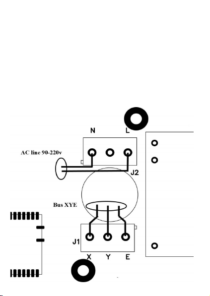
Wiring

Systems with indoor
units series 1 or 2 :
connect the bus to
the indoor units as
shown in Fig. 2
Systems with all indoor units series 4
and outdoor units series XRV Plus :
connect the bus X-Y-E as shown in
Fig 2/1
Connect the appliance directly to the
master outdoor unit, checking that the
addressing setting is automatically selected (see outdoor unit instructions)
Reinstall the terminal cover.
Close the unit, making sure to insert the hooks into the seats.
First configuration
When powered, the centralized control emits a double beep if it
is configured to connect in a local Wi-fi (default), or a single
beep if it is configured to connect in a network with Wi-fi modem. After a few seconds, another beep is emitted to indicate
that the centralized control is ready to operate. If a double beep
is heard when the unit is powered, you can proceed with the
parameter configuration to connect the centralized controller in
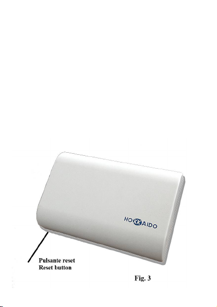
a network with Wi-fi modem. Otherwise, to set the unit so that
it can connect in a local Wi-fi, press for 1 sec. the button
through the hole. (see Fig. 3)

Download “Hokkaido 2.0” software from
www.hokkaidobms/download.
Connect to “Hokkaido_XRV” network and launch the app.
Enter the “Network” screen and deactivate the button “Use
sensor network”.
Fill in the fields with the appropriate data of your router, and
press “Set”. Now the centralized controller will beep and will
connect to your network.
Exit the application; reconnect to your network and launch the
app. again.If you have not used the DHCP, you will be able
already to display settings. In the case of active DHCP, go to
the “Network” screen and press the button “Search”.
The app will search to find the assigned IP address and to store
it for subsequent access.

Panel
The operating state is displayed for each unit connected.
A) Update the list of indoor units.
B) Modify the operating parameters of all indoor units
C) Select the indoor units on which to execute the changes
(after you have made your selection, press “Set”, see the
following paragraph Operation Settings)
D) Double click to change the settings of a single unit
 Loading...