

SCANTER 1002 Radar System
TLM
User’s Manual
© Terma, Denmark. Proprietary and intellectual rights of Terma A/S and/or its subsidiaries are involved in the subject-matter of this material and all
manufacturing, reproduction, use, disclosure, and sales rights pertaining to such subject-matter are expressly reserved. This material is submitted for
a specific purpose as agreed in writing, and the recipient by accepting this material agrees that this material will not be used, copied, or reproduced in
whole or in part nor its contents (or any part thereof) re vealed in any man ner or to any third part y, except own staff, t o meet the purpose f or which it was
submitted and subject to the terms of the written agreement.
This document is released for use only if signed by
relevant staff or stamped "EDM Release Controlled".
. .
CM:
..
1255194-HO Rev. A


Record of changes
Description Rev Date
Released A 2017-12-04
SCANTER 1002 Radar System
User’s Manual
1255194-HO
Page 3/62
Rev. A
2017-12-04

(Intentionally left blank)
Page 4/62
Rev. A
2017-12-04
SCANTER 1002 Radar System
User’s Manual
1255194-HO

1 Introduction . . . . . . . . . . . . . . . . . . . . . . . . . . . . . . . . . . . . . . . . . . . . . . . . . . . . 7
1.1 Purpose. . . . . . . . . . . . . . . . . . . . . . . . . . . . . . . . . . . . . . . . . . . . . . . . . . . . . . . . . . . . . . .7
1.2 Warnings and safety instructions . . . . . . . . . . . . . . . . . . . . . . . . . . . . . . . . . . . . . . . . . . .7
1.2.1 Microwave radiation safety margins. . . . . . . . . . . . . . . . . . . . . . . . . . . . . . . . . . . .9
1.2.2 Physical safety. . . . . . . . . . . . . . . . . . . . . . . . . . . . . . . . . . . . . . . . . . . . . . . . . . . .9
1.3 References . . . . . . . . . . . . . . . . . . . . . . . . . . . . . . . . . . . . . . . . . . . . . . . . . . . . . . . . . . . .9
2 SCANTER 1002 Radar System . . . . . . . . . . . . . . . . . . . . . . . . . . . . . . . . . . . . 11
2.1 System components . . . . . . . . . . . . . . . . . . . . . . . . . . . . . . . . . . . . . . . . . . . . . . . . . . . .12
2.2 SCANTER 1002 product features. . . . . . . . . . . . . . . . . . . . . . . . . . . . . . . . . . . . . . . . . .13
2.2.1 Embedded tracker (ET2) . . . . . . . . . . . . . . . . . . . . . . . . . . . . . . . . . . . . . . . . . . .13
2.2.2 Physical appearance of SCANTER 1002 . . . . . . . . . . . . . . . . . . . . . . . . . . . . . .14
3 Functional Description . . . . . . . . . . . . . . . . . . . . . . . . . . . . . . . . . . . . . . . . . . 15
3.1 Software-defined functionality. . . . . . . . . . . . . . . . . . . . . . . . . . . . . . . . . . . . . . . . . . . . .16
3.2 SSPA - Solid State Power Amplifier . . . . . . . . . . . . . . . . . . . . . . . . . . . . . . . . . . . . . . . .16
3.3 Frequency diversity. . . . . . . . . . . . . . . . . . . . . . . . . . . . . . . . . . . . . . . . . . . . . . . . . . . . .16
3.4 Full coherency. . . . . . . . . . . . . . . . . . . . . . . . . . . . . . . . . . . . . . . . . . . . . . . . . . . . . . . . .17
3.5 Pulse compression . . . . . . . . . . . . . . . . . . . . . . . . . . . . . . . . . . . . . . . . . . . . . . . . . . . . .17
3.6 Power sector transmission . . . . . . . . . . . . . . . . . . . . . . . . . . . . . . . . . . . . . . . . . . . . . . .18
3.7 Environment adaptation . . . . . . . . . . . . . . . . . . . . . . . . . . . . . . . . . . . . . . . . . . . . . . . . .18
3.8 Controlling and using the radar. . . . . . . . . . . . . . . . . . . . . . . . . . . . . . . . . . . . . . . . . . . .19
3.8.1 Remote control. . . . . . . . . . . . . . . . . . . . . . . . . . . . . . . . . . . . . . . . . . . . . . . . . . .19
3.8.2 Profiles. . . . . . . . . . . . . . . . . . . . . . . . . . . . . . . . . . . . . . . . . . . . . . . . . . . . . . . . .19
3.8.3 Built-in Test Equipment (BITE) . . . . . . . . . . . . . . . . . . . . . . . . . . . . . . . . . . . . . .19
3.8.3.1 BITE - errors/warnings. . . . . . . . . . . . . . . . . . . . . . . . . . . . . . . . . . . . . .21
3.8.3.2 BITE status. . . . . . . . . . . . . . . . . . . . . . . . . . . . . . . . . . . . . . . . . . . . . . .21
3.8.3.3 BITE measurements . . . . . . . . . . . . . . . . . . . . . . . . . . . . . . . . . . . . . . .21
3.8.3.4 BITE logging. . . . . . . . . . . . . . . . . . . . . . . . . . . . . . . . . . . . . . . . . . . . . .21
4 Hardware interface. . . . . . . . . . . . . . . . . . . . . . . . . . . . . . . . . . . . . . . . . . . . . . 23
4.1 X1, Mains . . . . . . . . . . . . . . . . . . . . . . . . . . . . . . . . . . . . . . . . . . . . . . . . . . . . . . . . . . . .24
4.2 X2, Aux . . . . . . . . . . . . . . . . . . . . . . . . . . . . . . . . . . . . . . . . . . . . . . . . . . . . . . . . . . . . . .24
4.3 X3, LAN. . . . . . . . . . . . . . . . . . . . . . . . . . . . . . . . . . . . . . . . . . . . . . . . . . . . . . . . . . . . . .24
4.4 GND . . . . . . . . . . . . . . . . . . . . . . . . . . . . . . . . . . . . . . . . . . . . . . . . . . . . . . . . . . . . . . . .25
5 Radar Service Tool . . . . . . . . . . . . . . . . . . . . . . . . . . . . . . . . . . . . . . . . . . . . . 27
5.1 Installation. . . . . . . . . . . . . . . . . . . . . . . . . . . . . . . . . . . . . . . . . . . . . . . . . . . . . . . . . . . .27
5.1.1 System requirements. . . . . . . . . . . . . . . . . . . . . . . . . . . . . . . . . . . . . . . . . . . . . .27
5.1.2 Installing and starting the Radar Service Tool. . . . . . . . . . . . . . . . . . . . . . . . . . .27
5.2 RST features. . . . . . . . . . . . . . . . . . . . . . . . . . . . . . . . . . . . . . . . . . . . . . . . . . . . . . . . . .27
5.2.1 Authentication . . . . . . . . . . . . . . . . . . . . . . . . . . . . . . . . . . . . . . . . . . . . . . . . . . .27
5.2.2 Access levels. . . . . . . . . . . . . . . . . . . . . . . . . . . . . . . . . . . . . . . . . . . . . . . . . . . .27
SCANTER 1002 Radar System
User’s Manual
1255194-HO
Page 5/62
Rev. A
2017-12-04

5.2.3 User documentation . . . . . . . . . . . . . . . . . . . . . . . . . . . . . . . . . . . . . . . . . . . . . . 28
5.2.4 Parameters and BITE access. . . . . . . . . . . . . . . . . . . . . . . . . . . . . . . . . . . . . . . 28
5.2.5 Tools. . . . . . . . . . . . . . . . . . . . . . . . . . . . . . . . . . . . . . . . . . . . . . . . . . . . . . . . . . 28
5.2.6 Situation display . . . . . . . . . . . . . . . . . . . . . . . . . . . . . . . . . . . . . . . . . . . . . . . . . 28
5.3 RST screen layout. . . . . . . . . . . . . . . . . . . . . . . . . . . . . . . . . . . . . . . . . . . . . . . . . . . . . 28
5.3.1 RST keyboard and mouse actions . . . . . . . . . . . . . . . . . . . . . . . . . . . . . . . . . . . 30
5.3.2 General. . . . . . . . . . . . . . . . . . . . . . . . . . . . . . . . . . . . . . . . . . . . . . . . . . . . . . . . 30
5.3.3 Adjust text size . . . . . . . . . . . . . . . . . . . . . . . . . . . . . . . . . . . . . . . . . . . . . . . . . . 30
5.3.4 Situation perspective control . . . . . . . . . . . . . . . . . . . . . . . . . . . . . . . . . . . . . . . 30
5.3.5 RST menu navigation and search . . . . . . . . . . . . . . . . . . . . . . . . . . . . . . . . . . . 31
5.4 Preferences . . . . . . . . . . . . . . . . . . . . . . . . . . . . . . . . . . . . . . . . . . . . . . . . . . . . . . . . . . 32
5.5 Perspectives . . . . . . . . . . . . . . . . . . . . . . . . . . . . . . . . . . . . . . . . . . . . . . . . . . . . . . . . . 32
5.6 Radar Control . . . . . . . . . . . . . . . . . . . . . . . . . . . . . . . . . . . . . . . . . . . . . . . . . . . . . . . . 35
5.6.1 Starting transceiver. . . . . . . . . . . . . . . . . . . . . . . . . . . . . . . . . . . . . . . . . . . . . . . 37
5.6.2 Stopping transceiver. . . . . . . . . . . . . . . . . . . . . . . . . . . . . . . . . . . . . . . . . . . . . . 37
5.6.3 Creating sectors . . . . . . . . . . . . . . . . . . . . . . . . . . . . . . . . . . . . . . . . . . . . . . . . . 37
5.6.4 Creating ET2 tracking zones . . . . . . . . . . . . . . . . . . . . . . . . . . . . . . . . . . . . . . . 38
5.6.5 Backup/restore . . . . . . . . . . . . . . . . . . . . . . . . . . . . . . . . . . . . . . . . . . . . . . . . . . 38
5.6.5.1 Creating/restoring backup of configuration data. . . . . . . . . . . . . . . . . . 39
6 Software installation . . . . . . . . . . . . . . . . . . . . . . . . . . . . . . . . . . . . . . . . . . . . 43
6.1 Resetting IP address on transceiver to default (169.254.1.50) . . . . . . . . . . . . . . . . . . . 43
6.2 Replacing transceiver software . . . . . . . . . . . . . . . . . . . . . . . . . . . . . . . . . . . . . . . . . . . 44
7 BITE errors and warnings . . . . . . . . . . . . . . . . . . . . . . . . . . . . . . . . . . . . . . . . 45
8 Technical terms and definitions . . . . . . . . . . . . . . . . . . . . . . . . . . . . . . . . . . . 51
9 Abbreviations and acronyms . . . . . . . . . . . . . . . . . . . . . . . . . . . . . . . . . . . . . 55
10 Annex A - Acknowledgement . . . . . . . . . . . . . . . . . . . . . . . . . . . . . . . . . . . . . 57
Page 6/62
Rev. A
2017-12-04
SCANTER 1002 Radar System
User’s Manual
1255194-HO

1 Introduction
1.1 Purpose
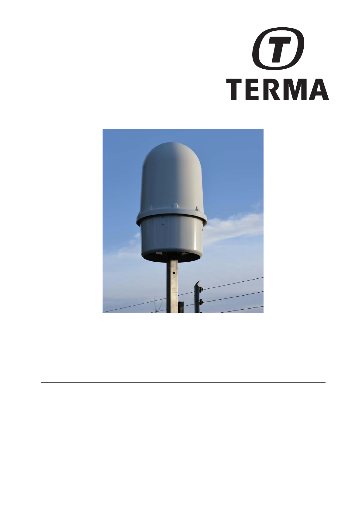
The SCANTER 1002 Radar System is optimized to ensure a high level of situational awareness on land platforms in all weather conditions.
The purpose of this manual is to provide a functional description of the radar system and the transceiver hardware interface.
The manual also provides a guide to the Radar Service Tool software application
used to control and monitor the system.
1.2 Warnings and safety instructions
The following outlines basic warnings and safety instructions when working on the
radar system. Further warnings and safety instructions can be found in doc. no.
970637-HT: “Warnings and Safety Instructions for Terma Radar Antenna Systems”.
SCANTER 1002 Radar System
User’s Manual
1255194-HO
Page 7/62
Rev. A
2017-12-04
In no event, Terma A/S shall be held liable for any direct, indirect, punitive, incidental or consequential damages whatso-ever arising out of or connected with the use or misuse of its products.
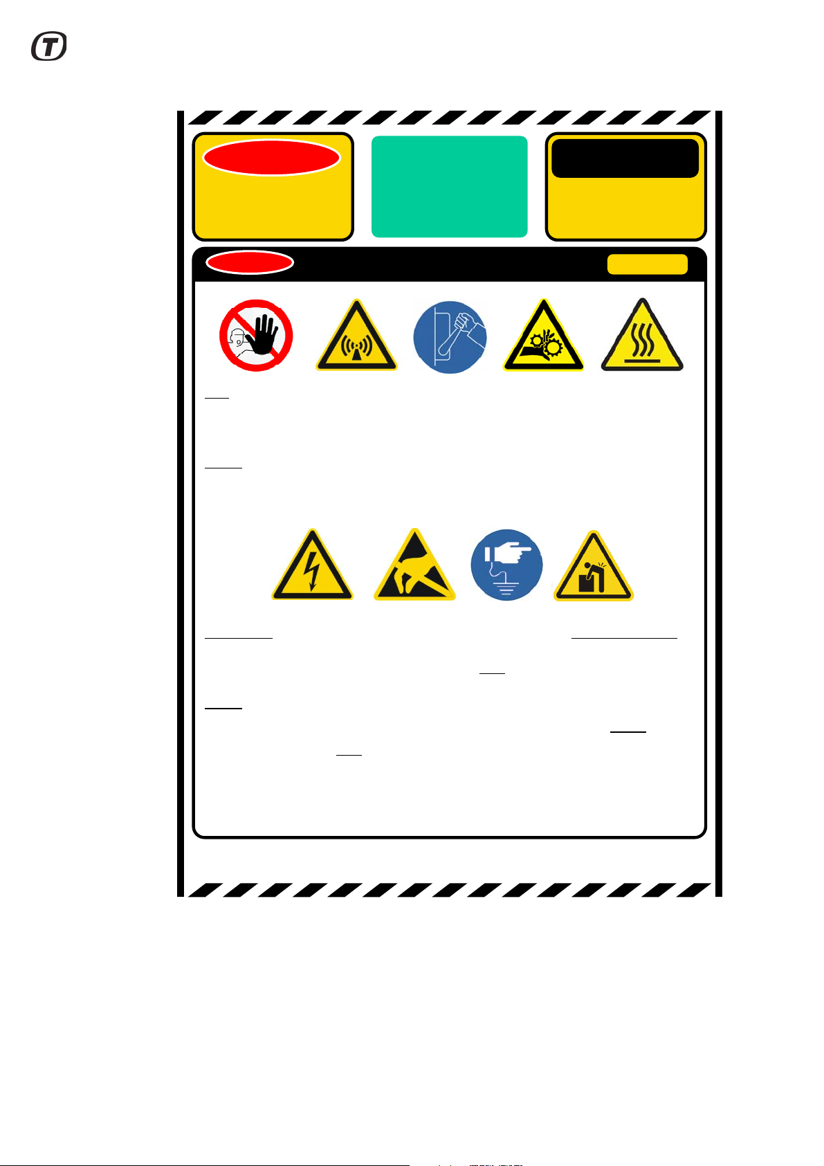
Only maintenance for authorized personnel.
This radar produces low power non-ionising electromagnetic radiation. Radiation is normally
not dangerous for the human body, however precautions should be taken, and a safety
distance of 1 meter when operating should be kept.
Always disconnect power before maintaining the radar. The rotating antenna may cause
injury.
Part of the equipment may have hot surfaces. Precautions should be made.
MAINTENANCE OF THE RADAR SYSTEM
WARNING
SAFETY
FIRST
WARNINGS,
CAUTIONS AND
SAFETY
INSTRUCTIONS
AUTHORIZED
PERSONNEL
ONLY
CAUTION
CAUTION
High voltage may be present at several points of the equipment. Observe and follow all
electrical safety precautions. These voltages may cause injury or even death.
When maintaining The radar, radar and instruments must be connected to the same electrical
protective ground.
Always use ESD (Electrostatic Sensitive Device) precautionary procedures when handling
ESD marked modules. The equipment contains components sensitive to damage by
electrostatic discharge. Wrist strap connected to earth bonding point must always be used
when handling unshielded electronics. Modules must be stored in static shielding packaging
(EIA-541). Module repair must be done on a ESD workstation, by qualified personnel.
Equipment weighs about 35 kilograms and to avoid injury, use proper lifting technique, 2
person lifting or lifting aids.
WARNING
Page 8/62
Rev. A
2017-12-04
SCANTER 1002 Radar System
User’s Manual
1255194-HO

1.2.1 Microwave radiation safety margins
Additional safety margins in respect of microwave radiation can be obtained by
increasing distances to the radiating antennas.
As a rule of thumb, the power density is inversely proportional to the square of the
distance from the radiating source. Thus, increasing the distance with a factor of 10
will reduce the power density with a factor of 100.
However, this is only true in the far fields distance.
• According to the ICNIRP guideline, the limit for the incident power density
level for the general public is 10 W/m
GHz and over any 6 minute period. The SCANTER 1002 radar operates
within this frequency range. The corresponding level for occupational exposure is 50 W/m
Furthermore, sector transmission is normally implemented, stopping transmission
for the parts of the antenna rotation not covering the ground surface. Also, power
sectors can be defined in which the transmitted power is reduced.
For additional safety, the SCANTER 1002 transmitter is closed down when antenna rotation is stopped.
Further information is available in doc. no. 721099-RK.
1.2.2 Physical safety
Be careful and use extreme caution when removing and lifting heavy objects as this
can cause physical injuries.
For rotating machinery in normal operation, the hazard zone is inside the cover of
the radar and is not accessible for any operator.
1.3 References
2
in the frequency band from 1-300
2
.
721002-DP SCANTER 1002 GSR Radar - Product Specification
357641-HO SCANTER Radar Service Tool - Operator’s Manual
357641-HI SCANTER Radar Service Tool - Installation Manual
721089-RA SCANTER 1000 Series Transceiver Core Software Open
721089-SC SCANTER 1000 Series Transceiver Core SW GPL Source Code
721099-RK SCANTER 1000 Series Antenna Power Density Analysis
970637-HT Warnings and Safety Instructions for Terma Radar Antenna Sys-
SCANTER 1002 Radar System
User’s Manual
1255194-HO
Source Licenses
tems
Page 9/62
Rev. A
2017-12-04

(Intentionally left blank)
Page 10/62
Rev. A
2017-12-04
SCANTER 1002 Radar System
User’s Manual
1255194-HO
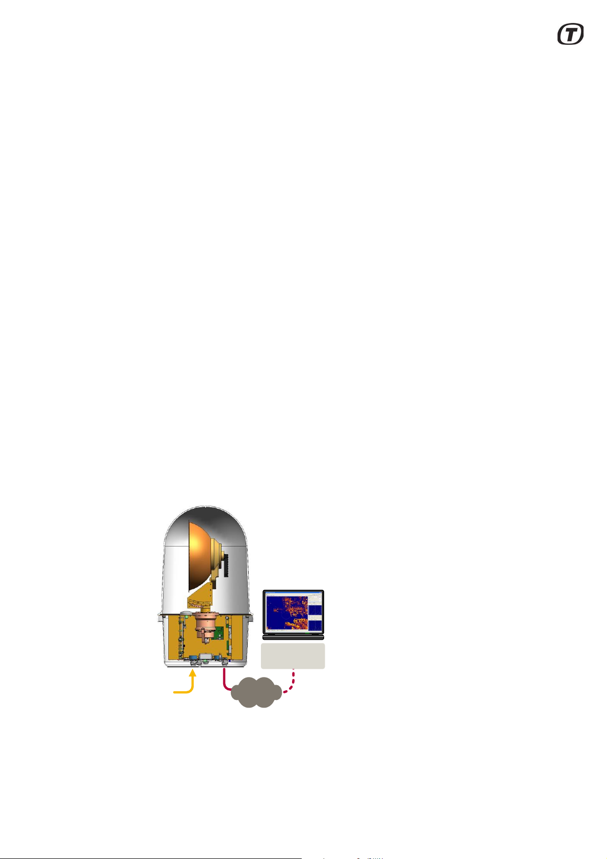
2 SCANTER 1002 Radar System
Radar Service
Tool
Power
IP network
The SCANTER 1002 Ground Surveillance Radar (GSR) is designed to perform
ground surveillance of high-sensitivity areas and critical infrastructure.
The SCANTER 1002 radar is a Ku-band, 2D, fully coherent pulse compression
radar, based on Solid State transmitter technology with digital software-defined
functionality.
Both the radar transmitter and receiver, the signal processing electronics, the
embedded tracker and the antenna are enclosed inside a radome, giving an
extremely compact and portable system.
SCANTER 1002 meets the requirements for professional GSR, where detection of
slow and fast-moving targets in adverse weather conditions is required.
Terma’s proven pulse compression technology, Frequency Diversity (FD) combined with the unique discrimination between stationary and slowly moving targets
gives a truly high-end surveillance radar system.
SCANTER 1002 uses Solid State Power Amplifier (SSPA) transmitter technology,
which ensures long service life and high availability.
A receiver with low noise and superior dynamic range provides high resolution and
detailed radar images, in all weather conditions, with no need for operator intervention. Combined with the advanced moving target filtering software, the system is
able to discriminate a walking or crawling man from the background clutter, even in
rain.
An embedded tracker (ET2) using Interacting Multiple Model technology and Multi
Hypothesis Tracking is integrated in the radar unit to detect and track agile and
small targets in severe weather conditions. The tracker is also used to detect large
vessels. Information to track surface targets is obtained from a combination of normal radar and Doppler-processed signals.
Fig. 2.1 Simplified system components schematics
SCANTER 1002 Radar System
User’s Manual
1255194-HO
Page 11/62
Rev. A
2017-12-04
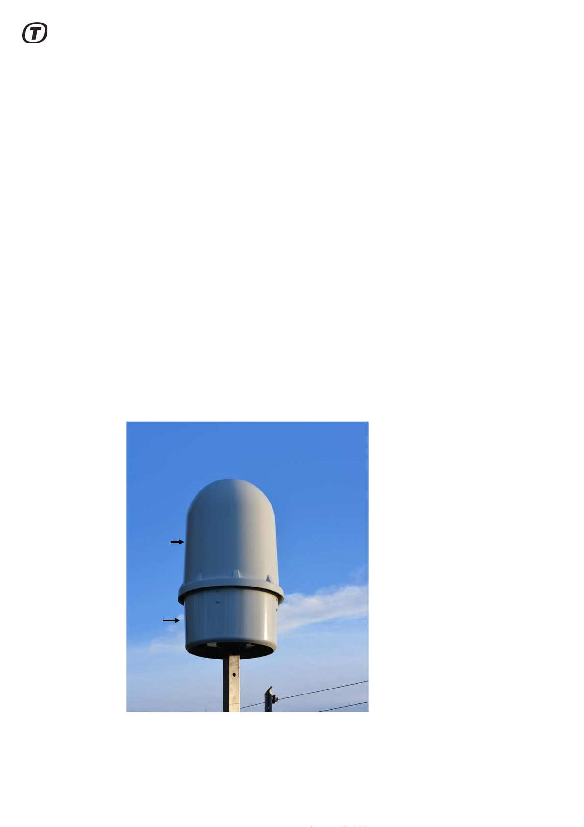
Communication interface to the transceiver is established via a standard IP net-
Radome
Sun
cover
work (LAN or WAN), which provides network radar video, plots, tracks, control, etc.
Service information is obtained via the IP network.
The SCANTER Service Display (Radar Service Tool) provides an easy interface for
controlling the radar and gives detailed status and diagnostics information from the
Built-in Test Equipment (BITE). It also provides access to powerful radar imaging
and tracking information.
2.1 System components
The SCANTER 1002 Radar System is mounted in an enclosure consisting of a
radome and a sun cover (see Fig. 2.2 (p. 12)). The system consists of the following
main assemblies and modules:
• Antenna system including antenna radiating the RF power (and subsequently
receiving the radar echoes), and antenna motor including azimuth encoder,
rotary joint and waveguide filter
• Transceiver including power supply module (PSU Module), transceiver module
(TR Module), processing and control module (PC Module), Motor Controller
Module, bottom plate with internal/external interfaces, and top plate holding
antenna system and GPS antenna
The antenna is a parabolic reflector with a horizontally polarized pencil beam.
It has a beam width of <4 degrees in azimuth, and the gain of the bea m is >= 32 dBi.
Page 12/62
Rev. A
2017-12-04
Fig. 2.2 SCANTER 1002 Radar System
SCANTER 1002 Radar System
User’s Manual
1255194-HO

2.2 SCANTER 1002 product features
Featuring
GSR Ground Surveillance, full c oherency and frequency diversity
Freque ncy
Program mable frequencies between 17.1–17.3 GHz
4 sub-bands
Transmitter
8 W SSPA
Receiver
Digital sampling on IF in 12 bits at 200 MHz
Range cell size: 6 m (3 m at instrumented range ≤ 6 km)
External Interfaces
IP network radar s ignals
Control and m onitoring via IP network / serial connec tion ports
Design
Encapsulated, integrated unit arc hitecture
Maintenance
Remote acc ess to radar video, control and monitoring
BITE for fault m anagement and diagnosis
Antenna
Parabolic reflector
Standards
CE, IEC, UL-60950
The SCANTER 1002 technology and product features are listed in the tables
below.
• Software-defined functionality
• Frequency diversity
• Full coherency and pulse compression
• Transmitter power level control in sectors
• Environment adaptation
• Control / profiles / BITE
2.2.1 Embedded tracker (ET2)
SCANTER 1002 Radar System
User’s Manual
1255194-HO
Fig. 2.3 SCANTER 1002 product features
SCANTER 1002 is equipped with an embedded tracker (ET2), which automatically
identifies moving objects in the radar image. The tracker assigns to each object a
unique identity; determines the position, speed an d course of the object; follows the
track of the object by predicting its position from scan to scan, and makes this information available in the radar image.
Page 13/62
Rev. A
2017-12-04
The embedded tracker detects and tracks any moving object. It gives the operator
an overview of moving objects, which the normal radar video alone cannot provide.
The tracker combines the information from the different Doppler filter channels with
the scan-to-scan movements in the normal video to achieve separation of small
moving targets from ground clutter.
2.2.2 Physical appearance of SCANTER 1002
Page 14/62
Rev. A
2017-12-04
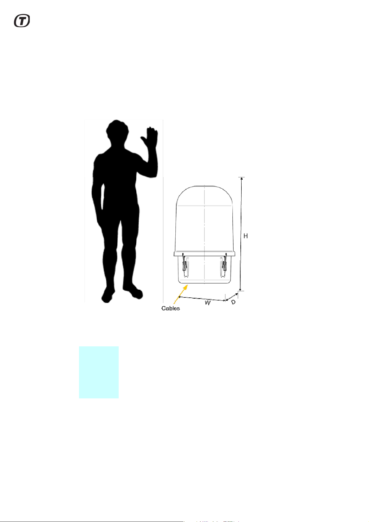
Fig. 2.4 Transceiver dimensions (model)
Weight: 35 kg installed
~ 50 kg packed for transportation
H x W x D 850 x 500 x 500 mm installed
~ 1090 x 800 x 600 mm packed for transportation
SCANTER 1002 Radar System
User’s Manual
1255194-HO
3 Functional Description
PC Module
Map interface
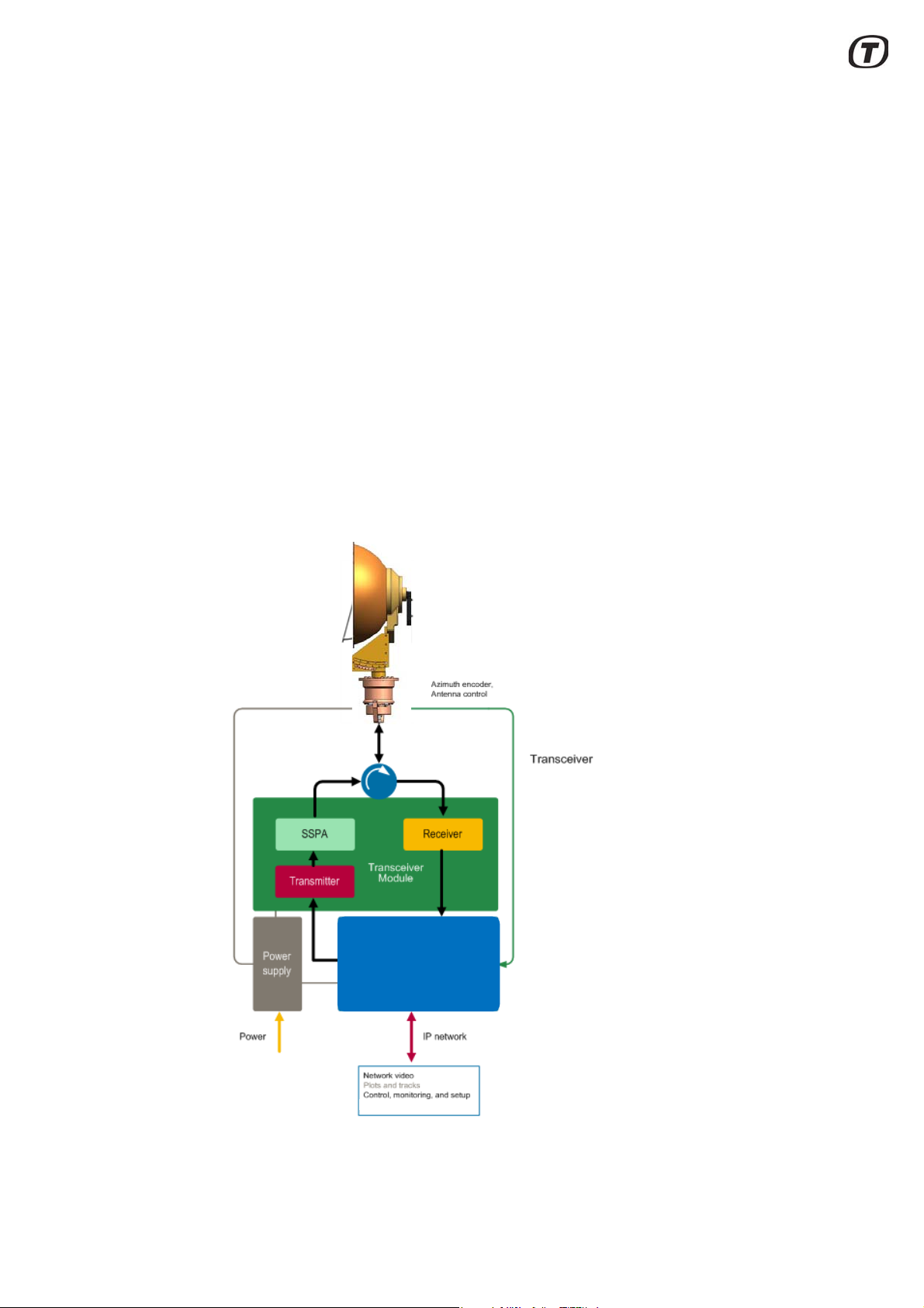
The SCANTER 1002 Radar System is an integrated unit containing both the radar
transceiver, power supply, embedded computer and antenna with motor and
encoder. The system is enclosed in a radome and a sun cover, which p rovide environmental protection and passive cooling.
The transceiver utilizes frequency modulation (chirping or frequency sweeping)
and pulse compression to increase the range resolution as well as the S/N (signalto-noise) ratio. This allows for transmission of long frequency-modulated chirps
with low peak power, and the ability of high range resolution and probability of
detection.
The system uses Digital Frequency Synthesis to generate chirps within the fo ur frequency bands, which can be selected by the application. The signal is generated
in the PC module, which contains the SCANTER 1002 transceiver processing section. The receiver will automatically tune to the transmitted frequency bands and
pass the received signal to the PC Module which will sample the signal, demodulate it, perform pulse compression and post-processing. This will generate radar
video used for plot extraction and tracking.
SCANTER 1002 Radar System
User’s Manual
1255194-HO
Fig. 3.1 Transceiver block diagram
Page 15/62
Rev. A
2017-12-04

3.1 Software-defined functionality
Multiple types of SCANTER radars utilize identical core software, which enables a
high level of testability, ensures deployment flexibility and makes it easy to add new
functionality.
A variety of radar signal processing techniques are available. Multiple functions,
such as automatic adaptation to weather scenarios, etc. are performed simultaneously. This, in combination with the use of multiple, identical and powerful commonplatform processing modules, leads to the concept “software-defined functionality”.
The entire processing structure is defined by software and functions relevant for the
individual application and can be invoked as appropriate. It is also possible to
switch between different modes of operation by modifying both the synthesized
transmit waveforms and receive signal processing tasks, even on the fly. All settings can be specified in a profile, making configuration easy.
In summary, the radar transceiver is configured to the application scenario, and
adaptation to the environment is highly automated.
3.2 SSPA - Solid State Power Amplifier
The SSPA - Solid State Power Amplifier - for SCANTER 1002 is part of the TR
Module in the transceiver. It is designed using state-of-the-art MMIC (Monolithic
Microwave Integrated Circuit) GaAs high-power amplifiers (HPA). The SSPA
amplifies the signal to be transmitted and produces 8 watt of Ku-band microwave
power.
The power sector mode feature allows the SSPA output power to be adjustable in
azimuth sectors or turned off. This is achieved by sector wise attenuating the input
signal into the SSOA from the transmitter.
3.3 Frequency diversity
One of the most difficult challenges for a GSR system is to separate a small target
from background clutter. In SCANTER 1002 this is achieved by a combination of
transmission diversity and intelligent signal processing.
The effect of the Terma SCANTER frequency diversity is to reduce fluctuation of
the echo from desirable targets, thereby enhancing targets relative to clutter. In
combination with coherent pulse compression and interference filtering, the radar
images become clear and well-suited for tracking.
A prerequisite for the frequency diversity is the ability of the transmitter to change
frequency instantaneously from chirp to chirp. The transmitter and receiver support
four sub-bands and can freely jump between these frequencies according to predefined profiles.
The advantage of using frequency diversity is that the noise and clutter will be different in the frequency bands, while the echo from the target remains con stant. This
means that the clutter can be cancelled by integrating echoes from different time
intervals and different frequencies.
Page 16/62
Rev. A
2017-12-04
Full benefit from the frequency diversity is obtainable only if dynamic characteristics are adapted to actual weather and complex clutter situations.
SCANTER 1002 Radar System
User’s Manual
1255194-HO
The sensitivity is therefore matched to the actual clutter levels, providing optimum
detection at all ranges and in all directions.
Furthermore, receivers and the processing chain have sufficient dynamic range
and all components provide sufficient resolution to handle the variety of signals
coming from small and large targets at all ranges. This contributes substantially to
the quality of the of the radar images. In addition, high resolution improves discrimination of clutter from wanted targets, thereby allowing the processing to separate
targets from clutter.
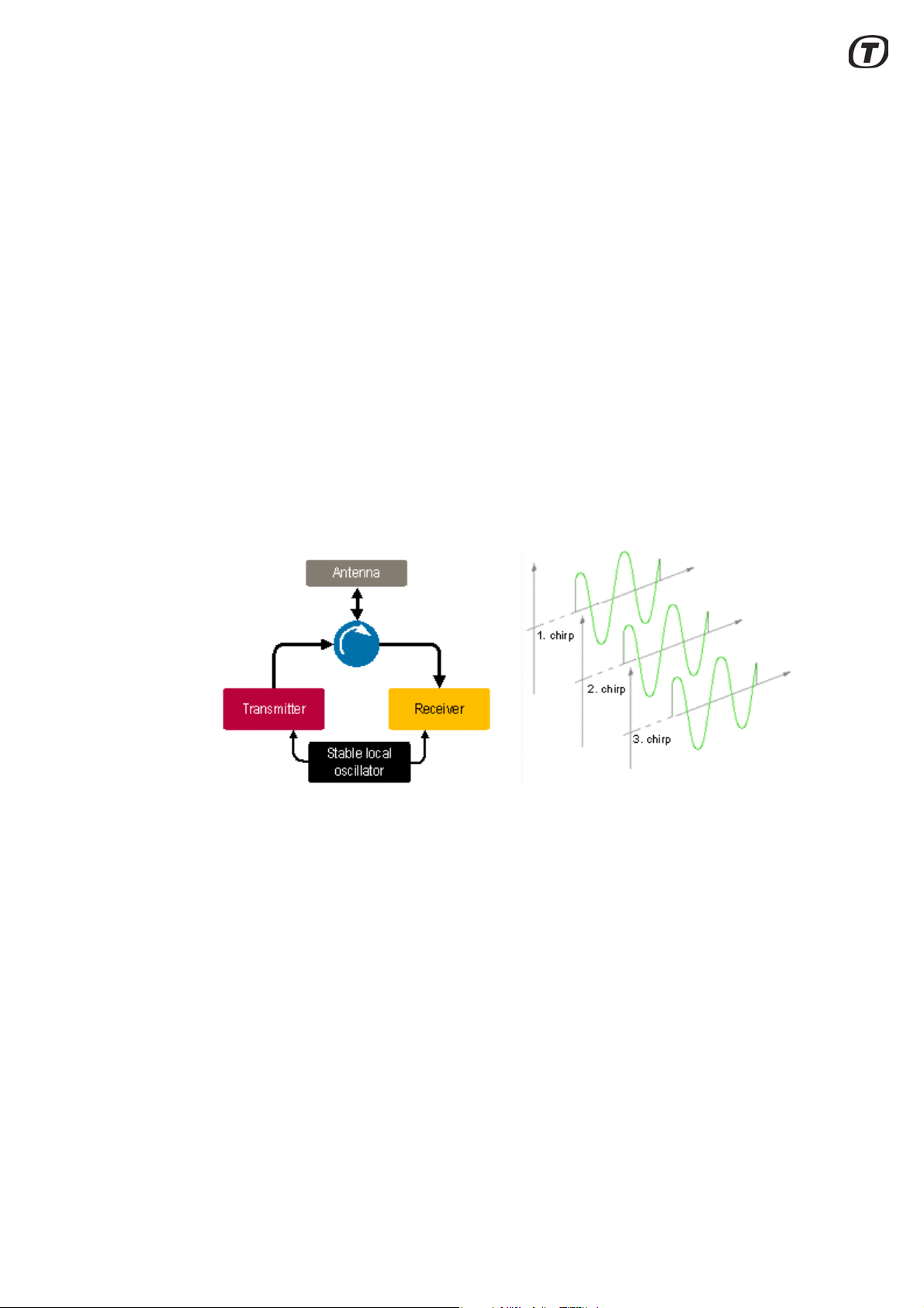
3.4 Full coherency
SCANTER 1002 is fully coherent utilizing amplitude and phase information during
transmission and reception. A common, phase stable reference oscillator is used
for transmission and reception. Coherency enables pulse compression and allows
the receiver to compare the phases of the received echoes from chirp to chirp and
thereby detect if targets are moving or not, utilizing the Doppler shift.
In order to detect moving targets, SCANTER 1002 also includes Doppler processing. This improves detection of targets moving radial (moving in range) and with a
radial speed different from clutter.
Fig. 3.2 Coherency principle
3.5 Pulse compression
A compact solid-state radar with low power consumption, SCANTER 1002 has a
limited peak power. In order to illuminate a target with sufficient energy for detection, it has to transmit long pulses. Unless some clever processing is used, this
would lead to a significant loss of range resolution. The SCANTER 1002 transceiver utilizes frequency modulation (chirping or frequency sweeping) and pulse compression to increase the range resolution as well as the signal-to-noise ratio.
When closely separated targets reflect these chirps, the frequency content of the
echoes from different targets at a given time will be different, as illustrated in
Fig. 3.3 (p. 18).
SCANTER 1002 Radar System
User’s Manual
1255194-HO
Page 17/62
Rev. A
2017-12-04

Fig. 3.3 Pulse compression principle
Antenna
Transmitter
Receiver /
Processing
Power
Power
Antenna
Transmitter
Receiver /
Processing
PowerPower
PowerPower
AB
AB
Echo
Chirp wit h
frequency sweep
Equivalent
compressed power
3.6 Power sector transmission
In order to avoid interference from strong echoes from large stationary targets like
buildings, mountains or ship superstructure and to reduce the risk of interfering with
other Ku-band systems, a power sector mode is available. This feature allows definition of up to 16 individual user defined sectors where the transmitted power can
be controlled. Each sector is defined as either:
• Prohibit sector
•Transmit sector
• Reduced power sector
The sectors are aligned relative to north.
Prohibit sectors take precedence over transmit sectors.
For the transmit sectors the power may be attenuated by up to 16 dB in each sec-
tor, thus providing a mode with low RF emission.
3.7 Environment adaptation
Page 18/62
Rev. A
2017-12-04
A false alarm is an erroneous radar target detection caused by clutter, noise or other interfering signals exceeding the detection threshold. In general, it is an indication of the presence of a radar target when there is no valid target.
Land suppressor adjusts the sensitivity to the stationary surroundings. Scan integration of SCD - Sea Clutter Discrimination - increases the suppression of clutter
and detection of slow-moving targets.
CFAR – Constant False Alarm Rate – and other adaptation techniques provide
automatic adjustments such as false alarm rate. CFAR provides a flat noise floor also based on proprietary algorithms.
SCANTER 1002 Radar System
User’s Manual
1255194-HO

3.8 Controlling and using the radar
BITE MeasurementsBITE StatusBITE Errors & Warnings
Built In Test Equipment (BITE)
3.8.1 Remote control
The radar can be controlled and monitored remotely in the following ways:
• In the Radar Service Tool application, a software package connects to the
transceiver via an IP network connection. From the software package all
parameters, settings, BITE measurements and errors can be accessed.
• Via an open IP network protocol, all parameters, settings, BITE measurements and errors can be accessed.
3.8.2 Profiles
Profiles are predefined parameter sets used to set optimal transceiver performance
according to varying weather conditions or specific operational demands. Thus, the
16 available profiles allow the operator to adjust the radar system transmission
mode and/or receiver processing in a fast and reliable way.
The profiles eliminate the risk of maladjustment of the radar and reduce the operator need to acquire detailed knowledge about radar characteristics and meaning
as such.
At any time, the operator may set a specific radar parameter, e.g. pulse width, to
override the definition of the profile.
The profiles are selectable via the Service Display (Radar Service Tool) or per
remote IP network.
3.8.3 Built-in Test Equipment (BITE)
Continuous status monitoring of a significant number of parameters/signals on
each module is performed in real time by the housekeeping system. The status of
the parameters/signals is internally assessed to initiate appropriate actions automatically to maintain operation to the extent possible if an error is detected.
The BITE reporting, see Fig. 3.4 (p. 19), clearly describes the actual event or error
and relates it to a specific module, i.e. no need for translation of code numbers. The
details of these reports will allow identification to the level of the Line Replaceable
Unit (LRU) at fault.
Fig. 3.4 Built-In Test Equipment (BITE)
At power up, the following diagnostic tests are performed:
SCANTER 1002 Radar System
User’s Manual
1255194-HO
Page 19/62
Rev. A
2017-12-04

• Module presence test
• Data link test
• Memory test of all RAM circuits.
The BITE monitors the system during standby and operation and reports the following:
BITE errors/warnings: Signal activity and processes
Internal supply voltages
Internal voltages and temperatures
Status from motor.
BITE status: Displays transceiver components status
BITE measurements: Temperatures
Internal power supplies.
If parameters exceed specifications, warnings or error messages are automatically
issued to the various human user interfaces available.
Page 20/62
Rev. A
2017-12-04
SCANTER 1002 Radar System
User’s Manual
1255194-HO

3.8.3.1 BITE - errors/warnings
Errors and warnings are used to report the presence of abnormal conditions detect-
ed by the transceiver software and include the following information:
Title: The title of a BITE error/warning is a short text indicating the
abnormal condition and/or the transceiver component to which it
applies, e.g. "High temperature".
Description: The description of a BITE error/warning is a text that can be used
to provide the system operator with an understanding of the context of the abnormal condition, e.g. "FPGA High Temperature
Fatal Error" indicates that the core temperature of the FPGA on
the processing board in slot 1 has exceeded the allowed maximum rating.
Severity: The severity of a BITE error/warning is used to indicate the impact
of the abnormal condition on transceiver operation.
There are three categories of severity and in addition warnings:
Fatal error, critical error and error.
A "fatal error" shuts down the system and a "critical error" stops
transmission.
Priority: The priority of a BITE error is used to indicate the relative impor-
tance of an error compared to other errors of the same severity.
3.8.3.2 BITE status
These messages indicate the state of transceiver components or entities of impor-
tance to the operational state of the transceiver, e.g. TX Status "On" / "Off".
3.8.3.3 BITE measurements
BITE measurements are used to periodically report a numerical measurement in
the transceiver and includes the following information: Title, description and value.
Measured parameters include temperatures, voltages, etc. For each measured
parameter, configuration of lower limit, upper limit, maximum update interval and
precision is defined.
3.8.3.4 BITE logging
Logging of BITE errors and warnings, BITE status and BITE measurements is per-
formed and data is stored in an allocated area of the hard disc on the embedded
computer. See Fig. 3.5 (p. 22).
SCANTER 1002 Radar System
User’s Manual
1255194-HO
Page 21/62
Rev. A
2017-12-04

Fig. 3.5 System and performance logs
Page 22/62
Rev. A
2017-12-04
SCANTER 1002 Radar System
User’s Manual
1255194-HO

4 Hardware interface
X1
X2 X3
GND
Bottom plate Conn. Function
X1 Mains, power in
X2 Aux
X3 LAN
GND Ground (protective earth)
Fig. 4.1 Bottom plate, connections
SCANTER 1002 Radar System
User’s Manual
1255194-HO
Page 23/62
Rev. A
2017-12-04

4.1 X1, Mains
Mains is supplied through the bottom plate and is the supply input for all modules
in the transceiver.
Description Data or Settings
Mains input 90-264 VAC
Frequency 47 - 63 Hz
Current 1A
Fuse 3.15AT
Connector Harting: Bulkhead type 09 40 703 0301 with 5
Terminal Function Terminal Function
1 Phase 1 4 Neutral
2NC 5NC
poles connector insert type 09 12 005 3001
3NC PEEarth
4.2 X2, Aux
The AUX interface is used for debugging by Terma personnel. It includes an IP
reset feature that may be applicable for end users. For details on IP reset, refer to
section 6.1 (p. 43).
Terminal Function Terminal Function
1 GND 5 Reserved
2 RS-232-Adm PC_TX 6 IP Reset
3 RS-232-Adm PC_RX 7 DFU
4 Reserved 8 NC
4.3 X3, LAN
The LAN interface is used for control of the radar and for track output.
Page 24/62
Rev. A
2017-12-04
Description Data or Settings
Interface standard Ethernet standard IEEE 802.3 10/100 BASE-T
Connector
Harting: Bulkhead type 09 40 703 0301 with
RJ45 insert type 09 45 200 1560
SCANTER 1002 Radar System
User’s Manual
1255194-HO

Terminal Function Terminal Function
1BI_DA+ 6BI_DB2 BI_DA- 7 BI_DD+
3 BI_DB+ 8 BI_DD4 BI_DC+ SHELL Shield
5 BI_DC-
4.4 GND
The ground stud is for connection to Protective Earth.
Fig. 4.2 Bottom plate, ground stud
SCANTER 1002 Radar System
User’s Manual
1255194-HO
Page 25/62
Rev. A
2017-12-04

(Intentionally left blank)
Page 26/62
Rev. A
2017-12-04
SCANTER 1002 Radar System
User’s Manual
1255194-HO

5 Radar Service Tool
The radar system can be managed through the Radar Service Tool (RST), which
is a software application used for controlling the radar system, such a s parameters
and BITE information, and for monitoring radar video, plots and tracks.
The RST runs on a laptop or on a PC connected to the radar LAN.
The RST provides the user with a consistent look and feel across the various fea-
tures implemented. It supports different perspectives, where each perspective corresponds to a particular arrangement and subset of RST windows (views). The
user may define, store and recall individual perspectives.
For detailed descriptions of the Radar Service Tool functions, see doc. no. 357641HO: “SCANTER Radar Service Tool - Operator’s Manual”.
5.1 Installation
5.1.1 System requirements
The system requirements for the computer running the RST are found in doc. no.
357641-HI: “SCANTER Radar Service Tool”.
5.1.2 Installing and starting the Radar Service Tool
To install the RST, use the 7-Zip application to extract the zip file from the CD
(357641-NF) to the computer. The startup file rst.exe is located in the directory:
"RST-357641-NF-<revision>-<Win/Linux>-<32/64bit>\rst".
Start the Radar Service Tool by double-clicking the "rst.exe" file. The user may create a shortcut to this file and place it on the desktop.
5.2 RST features
5.2.1 Authentication
The available access administration is:
• Access to the computer is protected by a normal Windows login.
5.2.2 Access levels
To operate or to change parameters in the radar it is necessary to connect to the
radar using one of the three access levels available:
• Operational access level.
• Service access level.
• Debug access level.
SCANTER 1002 Radar System
User’s Manual
1255194-HO
Page 27/62
Rev. A
2017-12-04

Operational access level allows the user to change the most commonly used
parameters and to operate the radar.
The service access level allows to change all parameters, while the debug access
level is intended for technicians having intensive and detailed knowledge about the
radar system.
5.2.3 User documentation
The RST “DocLib” view contains a list of documents stored on the transceiver, such
as technical manuals.
5.2.4 Parameters and BITE access
Access to all necessary parameters is available through the RST.
The RST provides status on radar functions and performance as well as detailed
status on all modules in the system. All BITE information available about the modules is shown together with any status or error message issued by the module.
5.2.5 Tools
In addition to live radar video, the RST provides the user with operator’s tools, such
as A-Scope, EBL, VRM, continuous zoom, histograms, primary-, secondary- and
AIS tracks, plots, maps, etc.
These operator’s tools allow the user to perform a detailed analysis of the system
performance. Display of track data is possible by clicking on the individual target,
in combination with a right-click menu.
5.2.6 Situation display
The situation display presents live video, A-Scope, EBL, VRM, continuous zoom,
histograms, primary-, secondary- and tracks, plots, maps, etc.
These operator tools are available to allow the user to perform more detailed
analysis of the system performance. Display of track data is possible by mouse
click on the individual target, in combination with a pop-up menu (right mouse click).
The situation display is one of five default perspectives, all described in the following.
5.3 RST screen layout
The Radar Service Tool screen layout is shown in Fig. 5.1 (p. 29) with definitions
of the different operation areas.
Page 28/62
Rev. A
2017-12-04
SCANTER 1002 Radar System
User’s Manual
1255194-HO

Fig. 5.1 RST, screen layout
Menu
Views
Left
side
bar
Views
Perspectives
Status bar
In the “Views” area of the screen, it is possible to open interactive views for display
and handling of graphical information e.g. radar video, measurement tools, radar
control, parameters, BITE information, etc.
Presentation of these views can be selected and deselected individually.
The five default perspectives are described in section 5.5 (p. 32).
The Radar Service Tool menu bar consists of “File”, “Window” and “Help”.
Fig. 5.2 Radar Service Tool - menus and submenus
The ”File” menu is used to exit the RST, while the “Help” menu displays the RST
software version and provides information on a number of topics as well as a
search function. The help topics can also be displayed by pressing the F1 key anywhere in the RST user interface.
SCANTER 1002 Radar System
User’s Manual
1255194-HO
Page 29/62
Rev. A
2017-12-04

In the “Window” menu, the submenu “Preferences” is used to set default colors,
units, snapshots storage directory, radar video setting such as decay, sweep, trails
history, video gain, etc.
“Show View” and “Open Perspective” are used to activate a view or a perspective.
The left side bar, shown in Fig. 5.1 (p. 29), is used to open fast views. A fast view
remains on the monitor as long as it is in focus. It will disappear from the monitor if
the operator clicks any place outside the fast view.
It is possible to reset predefined perspectives to the default layo ut.To do so, open
the perspective, right-click on the perspective button and choose "Reset".
5.3.1
RST keyboard and mouse actions
5.3.2 General
General
Maximize/Restore view Double left-click on view tab
Move view to another docking Left-drag view tab
5.3.3 Adjust text size
Adjust text size
Parameters view
Profile Editor view
Profile Names view
Errors/Warnings view
Status/Measurements view
Ctrl - scroll wheel
5.3.4 Situation perspective control
PPI view
Re-center Ctrl - right-click
Zoom Scroll wheel
Zoom in Ctrl - right-drag - up - right
Zoom out Ctrl - right-drag - down - left
Reset zoom and re-center to own
unit position
Page 30/62
Rev. A
2017-12-04
Ctrl - right-drag - up - left
SCANTER 1002 Radar System
User’s Manual
1255194-HO

A-Scope view
Collapse navigation tree Expand all
Minimize View into sidebar Maximize View
Zoom Scroll wheel
Pan/Adjust VRM circle Left-drag
VRM-Scope view
Zoom Scroll wheel
Pan/Adjust EBL angle Left-drag
Area Masking view
Press buttons “Delete Mask” or “Create Mask” to start creating a polygon
Add polygon vertices Left-click
Finish creating polygon Right-click
Delete last vertex while creating a polygon Ctrl - left-click
Abort current polygon creation Esc
5.3.5 RST menu navigation and search
Use the four buttons at the top to the right of the view to collapse the navigation tree
(All parameters) or to expand the tree. See Fig. 5.3 (p. 31). The view can be mini-
mized into a sidebar or maximized.
Fig. 5.3 RST, View control buttons
To search for a parameter, enter the parameter name in the “Parameter filter” or in
the “Scope filter” field. See Fig. 5.4 (p. 32). The shown search is sector 11. To
change a parameter value, simply click and enter the new value in the relevant
field. The “All parameters” in the navigation tree must be selected to enable the
search in the entire navigation tree.
SCANTER 1002 Radar System
User’s Manual
1255194-HO
In case a parameter cannot be found, pay attention to the log-on access level.
Page 31/62
Rev. A
2017-12-04

Fig. 5.4 RST, search filters
Parameter and Scope filters
Click value field to change
parameter value
5.4 Preferences
In the Preferences menu it is possible individually to change color and fonts. The
user can select what unit format to use, specify general settings of the RST, the PPI
(radar video, background, trails etc). The following sections describe the usage of
the RST Preferences.
Preferences
Color General Help
Perspectives Plug-ins RST Own Unit Override
Unit
Fig. 5.5 RST, preferences
5.5 Perspectives
When launching the RST program for the first time, there are fo ur default perspectives, each of these containing a certain number of views. The presentation of these
views can be selected and deselected individually.
Page 32/62
Rev. A
2017-12-04
The “Initial” perspective is used when a connection to the transceiver and its services is established. See Fig. 5.6 (p. 32).
Initial
Connection Manager Connection Status
Recordings
Fig. 5.6 “Initial” perspective, default
The “Low Level” perspective provides parameter and profile views for configuring
profile content and editing profile names.
SCANTER 1002 Radar System
User’s Manual
1255194-HO

The “Errors/Warnings” and “Status/Measurements” views are used to monitor the
health of the transceiver.See Fig. 5.7 (p. 33).
Low Level
Parameters Profile Editor Profile Names
Debug Errors/Warnings Status/Measurements
Recent Errors/Warnings
Fig. 5.7 “Low Level” perspective, default
The “Service” perspective is used for transceiver backup/restore and software
update. Further, it provides access to the documents/user guides stored in the
transceiver. See Fig. 5.8 (p. 33).
Service
Backup/Restore Software Update DocLib
Console
Fig. 5.8 “Service” perspective, default
The “Situation” perspective is used by the operator to start the radar and transmis-
sion, to select profile and to monitor the radar video. Measurement tools are included in this perspective. See Fig. 5.9 (p. 33).
Situation
PPI Parameters Debug
Video Setup Area Masking Radar Control
VRM-Scope Histogram A-Scope
Zones Markers Vectors
Fig. 5.9 “Situation” perspective, default
The “Zone Edit” perspective provides views for creating and editing zones and
zone parameters. See Fig. 5.10 (p. 33).
Zone Edit
Zones Legacy NAAZ Zones Legacy NTZ Zones
Parameters
Fig. 5.10 “Zone Edit” perspective - default
SCANTER 1002 Radar System
User’s Manual
1255194-HO
Page 33/62
Rev. A
2017-12-04

Any default perspective can be customized by adding or removing views freely
Open Perspective
4 Views in one frame
1 View in one frame
Open fast View
2 Views in one frame
selected by the user.
Alternatively, new personal perspectives can be created, which can be stored in the
perspectives area.
Views are placed inside the “Views” area, or “minimized” and placed in the sidebar
areas (right and left side) of the RST window.
Fig. 5.11 RST, Views
A view can be placed in its own frame, or several views can be placed in the same
frame/window. See Fig. 5.11 (p. 34).
To move a view within the view area, select the view tab with the left mouse button
while holding down the button. Move the view to another location or in side a frame
already containing one or more views.
Page 34/62
Rev. A
2017-12-04
SCANTER 1002 Radar System
User’s Manual
1255194-HO

5.6 Radar Control
When the Mains switch on the transceiver is turned to the Off position, the transceiver is in the “Off” state where it cannot function or be reached from remote.
The transceiver can enter any of the states shown in the below table:
Radar Control view in the
Radar Service Tool
Transceiver states External
Antenna Transmission
mains switch
Off Off - Standby On Off Off
Fully functioning On On On
The “Standby” state is entered when the external mains switch is switched on and
the transceiver has performed a booting procedure that may last for 3-5 minutes.
The transceiver is checking the presence and condition of all hardware modules.
In this state, the LAN ports on the External I/O module are up and running. An RST
client can then connect to the transceiver through the LAN network.
"Radar Control" view - Radar tab (Fig. 5.12 (p. 35)) is used for switching on/off the
antenna motor, the transmitter, and sector transmission.
Note that “Mains” cannot be switched off using the RST, but must be
switched off directly on the external switch.
Fig. 5.12 Radar Control view - Radar
To change transceiver configuration, the "Profile" drop down menu, see
Fig. 5.12 (p. 35), gives the possibility to select one of sixteen predefined profiles.
SCANTER 1002 Radar System
User’s Manual
1255194-HO
Page 35/62
Rev. A
2017-12-04

With "Antenna" it is possible to switch on and off the antenna motor. To the right is
Radar video attenuation:
0 means minimum attenuation
100 means maximum attenuation
Radar video gain:
50 equals unity gain
Range: (0-100)
Rain clutter attenuation:
0 means minimum attenuation
100 means maximum
attenuation
Tracker sensitivity:
50 means means normal sensitivity
(0: minimum sensitivity)
(100: maximum sensitivity)
shown the actual antenna rotation speed in RPM.
With "Tx" it is possible to switch on and off the transmitter. To the right is shown the
status of the transmitter (transmitting, stand by, etc.).
"Sector Tx" switches on and off the sector transmission and will affect all sectors
enabled.
“Force Active” is for use in redundant systems only, i.e. in SCANTER 1002 this but-
ton is dimmed.
“Exclusive Access” is used for requesting ‘master control mode’ of the radar. This
mode allows the user to gain exclusive access to the radar, i.e. lock the configuration parameters for sole use. Master control mode is defined in the parameter ‘Master Control Mode’ and can have the values ‘Disabled’, Optional’ or ‘Mandatory’. If
the parameter is set to ‘Optional’ or ‘Disabled’, the user must request master control
mode before being able to change configuration parameters. If set to ‘Disabled’,
exclusive access cannot be requested and the button will be dimmed. Exclusive
access can be released by pressing the button.
The “Radar Control” view - Sensitivity tab (Fig. 5.13 (p. 36)) is used for auto adjusment tracker sensitivity for surface and air channels.
Note: Manual adjustment is not supported for SCANTER 1002.
Page 36/62
Rev. A
2017-12-04
Fig. 5.13 “Radar Control” - Sensitivity
SCANTER 1002 Radar System
User’s Manual
1255194-HO

5.6.1 Starting transceiver
E
x
t
e
n
t
B
e
a
r
i
n
g
Step 1 Turn on power to the transceiver using the external power switch.
Step 2 Establish a connection between the transceiver and the RST by
means of the RST “Connection Manager” view.
Step 3 In the RST “Radar Control” view, select “Antenna”, “Tx” and an
appropriate profile.
Enable sector transmission if created and needed.
5.6.2 Stopping transceiver
Step 1 Switch off “Tx” and “Antenna” in the RST “Radar Control” view.
Step 2 Turn off power to the transceiver using the external power switch.
5.6.3 Creating sectors
In the “Parameters” view - Sectors, it is possible to set up sixteen independent sectors, selected as transmission sectors, prohibited sectors or reduced power transmitting sectors. All available as stabilized or non-stabilized sectors.
A stabilized sector is always kept relative to north. Not stabilized sectors will follow
the moving platform when it is turning, i.e. they are not kept relative to north.
When setting up a sector it is necessary to know or to calculate the b earing of the
sector, i.e. the middle. In the same way it is necessary to know or to calculate the
width (extent) of the sector (in degrees). See Fig. 5.14 (p. 37).
A prohibit sector is a non-transmission sector.
Selecting reduced power sector, it is possible to transmit with reduced power. Pow-
er attenuation is selectable in the interval 0..15.5 dB.
Fig. 5.14 Sector Bearing and Width
SCANTER 1002 Radar System
User’s Manual
1255194-HO
Page 37/62
Rev. A
2017-12-04

Sector bearing: 0..359 degrees
Sector width: 10.. 350 degrees
Sector mode: Disabled, prohibited, reduced power sector, transmitting
sector
Azimuth mode Stabilized or unstabilized
Sector attenuation 0..15.5 dB
5.6.4 Creating ET2 tracking zones
Tracking zones facilitate optimized control of tracking in specific areas.
The following types of tracking zones can be set up for a naval system (note the
conditions applying to AAZs):
• Automatic Acquisition Zone (AAZ): Automatic Acquisition Zones are areas
where tracking will be initiated automatically. AAZs must cover the entire
demanded tracking area.
Note: When the RST is used to control a transceiver, it must be connected
using Parameter Control Protocol v. 2.2 or newer, and the transceiver must
support creating and editing AAZs from this protocol.
• Non-Tracking Zone (NTZ): zone in which the tracker will not perform tracking
on plots. No tracks are initiated in the zone and thus no tracks are maintained.
• Non-Automatic Acquisition Zone (NAAZ): zone in which the tracker will not initiate tracks based on the plots within. Confirmed tracks moving into a NAAZ
will be maintained.
NTZ and NAAZ can be created and drawn in the PPI view using the "Zone Edit"
view.
Zones can be defined for air or surface channel, or for both air and surface channels.
5.6.5 Backup/restore
The backup and restore functions in the RST provide backup and restore facilities
for the SCANTER 1002 radar system.
The transceiver contains the application SW, factory default data, transceive r co nfiguration data and site default data.
Furthermore, some space is allocated for log files (i.e. performance and measurement data) and temporary files. See Fig. 5.15 (p. 39).
Page 38/62
Rev. A
2017-12-04
The data set currently being used by the transceiver is stored in the “Transceiver
configuration” memory area.
SCANTER 1002 Radar System
User’s Manual
1255194-HO

The “Site Default” data area is used to store a copy of the “Transceiver Configuration”. It is recommended to copy the “Transceiver Configuration” to the “Site
Default” area after Setting-To-Work (STW) and later on after major changes of the
settings.
Furthermore, it is recommended to back up the “Transceiver Configuration” and
logs, area masking and maps on the Radar Service Tool computer. When activating the backup from the RST, the FTP server will create and store a temporary
backup file which is then transmitted to the RST computer.
The “Temporary files” directory has a limited size, hence it is possible to delete
some of these files by means of the RST.
The “Factory Default” data area contains basic settings for the transceiver, created
and used at transceiver production. These data are not intended to be used on site.
Fig. 5.15 Transceiver - SW and configuration data
5.6.5.1 Creating/restoring backup of configuration data
Note: Antenna rotation must be stopped before initiating the backup.
To create a backup of the “Transceiver configuration” and log files, use the RST
“Backup/Restore” view. See Fig. 5.17 (p. 40).
The RST saves the backup file in the directory selected by the user:
For each zipped backup file, the date is used as the file name (i.e. BackupDate.tar).
The backup file contains all parameters for the transceiver and the radar system,
logs, area masking and maps.
The restore function copies the transceiver backup file from the RST computer to
the "Transceiver configuration" area. Once the backup file has been uploaded, the
transceiver will restart to activate and use the restored backup file.
The restore function is available in two variants: Partial Restore or Full Restore.
A “Full Restore” is used in situations where a complete replacement of the config-
uration of the transceiver is desired. This includes site specific settings such as IP
address, encoder alignment and calibration data. This is the type of restore to be
used when exchanging the LRU containing the transceiver hard drive or if a complete re-initialization of the transceiver to a previously backed up state is required.
SCANTER 1002 Radar System
User’s Manual
1255194-HO
Page 39/62
Rev. A
2017-12-04

A “Partial Restore”, on the other hand, replaces only configuration data not tied to
Create/restore transceiver
configuration file.
(Files are stored in the Service
Display computer and transceiver)
Restore Factory Default
configuration file
Create/restore Site Deafult
configuration file. (Files are stored
in the transceiver)
the specific transceiver on which it was created. This type of restore operation is
useful if the same basic configuration is to be reused across several transceivers.
A backup is then created on a master transceiver and partially restored on the
remaining transceivers.
Fig. 5.16 Partial/Full Restore
“Delete Temp” removes temporary files stored in the transceiver (FTP Server).
Page 40/62
Rev. A
2017-12-04
Fig. 5.17 Menu: Window / Show View / Backup/Restore
SCANTER 1002 Radar System
User’s Manual
1255194-HO

The “Site Default” create option copies the” Transceiver configuration” to the “Site
Default” area. Restore copies the “Site Default” to the “transceiver configuration”
area. The transceiver will restart to activate and use the new data.
The “Factory Default” data contains basic parameter values for the transceiver.
These are created at transceiver production and should not be used after the radar
has been set up.
Restoring the “Factory Default” data will delete the “transceiver configuration” area. The transceiver will then be out of service, unless a backup has
been created on the RST that can be restored.
SCANTER 1002 Radar System
User’s Manual
1255194-HO
Page 41/62
Rev. A
2017-12-04

(Intentionally left blank)
Page 42/62
Rev. A
2017-12-04
SCANTER 1002 Radar System
User’s Manual
1255194-HO

6 Software installation
6.1 Resetting IP address on transceiver to default (169.254.1.50)
This procedure should be performed if the connection to the transceiver cannot be
established. This may be the case if the transceiver has been replaced, or if the
transceiver is temporarily replaced with another transceiver, for instance in con nection with service.
Tool requirements: Screwdriver, flat
Spare parts / consumables: Reset Switch, X2 (902059-001) - part of toolkit
Service PC with Radar Service Tool (RST)
Network adapter
Est. time consumption 1/2 hour
1 Disconnect the external power cable on the transceiver.
2 Configure the network adapter o n the service PC with an IP address on the
169.254.0.0/24* LAN segment.
3 Connect the network adapter on the service PC directly to the LAN con-
nector (X3) on the transceiver.
4 Connect the Reset Switch, X2 (see
Fig. 6.1 (p. 43)) to the Aux connec-
tor (X2) on the transceiver and fasten the screws.
5 Toggle the switch on the Reset
Switch, X2 to ”IP Reset” mode.
Fig. 6.1 Reset switch, X2 in IP
reset mode
6 Connect the external power cable to the transceiver.
7 Wait for the bootloader to finish booting to “IP Reset” mode, as indicated
by the LED.
8 Toggle the switch on the Reset Switch, X2 to neutral position (middle).
9 In the RST “Parameters” view > Service and Installation\ Network Config-
uration, set “IP Address” to the final IP address for the transceiver on the
site in question. Also change “Default Gateway” and “Subnet Mask”
accordingly.
10 Set “Store Network Configuration” to ‘Store’ for changes to take effect.
*
According to the CIDR notation, ‘/24’ means that netmask must be set to 255.255.255.0
(24 bit set, 8 bit not set).
SCANTER 1002 Radar System
User’s Manual
1255194-HO
Page 43/62
Rev. A
2017-12-04

6.2 Replacing transceiver software
This procedure describes how to perform a Device Firmware Update (DFU). The
procedure should be performed if the transceiver PC Module has been replaced or
following an unsuccessful transceiver software update due to e.g. power failure.
Note: The procedure will erase all existing software on the transceiver.
Tool requirements: Screwdriver, flat
Spare parts / consumables: Reset Switch, X2 (902059-001) - part of toolkit
Service PC with Radar Service Tool (RST)
Network adapter
Est. time consumption 1/2 hour
1 Disconnect the external power cable on the transceiver.
2 Configure the network adapter on the service PC with an IP addre ss on the
169.254.0.0/24* LAN segment.
3 Connect the network adapter on the service PC directly to the LAN con-
nector (X3) on the transceiver.
4 Connect the Reset Switch, X2 (see
Fig. 6.2 (p. 44)) to the Aux connec-
tor (X2) on the transceiver and fasten the screws.
5 Toggle the switch on the Reset
Switch, X2 to “DFU” mode.
Fig. 6.2 Reset switch, X2 in DFU
mode
6 Connect the external power cable to the transceiver.
7 Wait for the bootloader to finish booting to “DFU” mode, as indicated by the
LED.
8 Toggle the switch on the Reset Switch, X2 to neutral position (middle).
9 Use the Radar Service Tool to upload transceiver core software (902085-
NF) to 169.254.1.50.
10 The transceiver will automatically reboot into the newly installed software.
According to the CIDR notation, ‘/24’ means that netmask must be set to 255.255.255.0
*
(24 bit set, 8 bit not set).
Page 44/62
Rev. A
2017-12-04
SCANTER 1002 Radar System
User’s Manual
1255194-HO

7 BITE errors and warnings
Name Min Max Severity Description
ADC Calibration Error Error
Antenna RPM Too Large Error Error
Error indicating that 'Antenna RPM' parameter value is larger
than 'Maximal Antenna RPM' calculated.
BITE Measurement Log Disk Limit
Reached
Error
Indicates that the amount of disk space allocated to the BITE
Measurement Log has been used up
BITE Status Log Disk Limit
Reached
Error
Indicates that the amount of disk space allocated to the BITE
Status Log has been used up
BITE Warning and Error Log Disk
Limit Reached
Error
Indicates that the amount of disk space allocated to the BITE
Warning and Error Log has been used up
CAN Bus Status#Motor Controller Error
Cancelable Call Warning#Motor
Controller
Warning
Chirp Reference Level Low Error#f0
Error
Indicates that the power of the transmitted signal as seen by the
receiver is lower than expected.
Chirp Reference Level Low Error#f1
Error
Indicates that the power of the transmitted signal as seen by the
receiver is lower than expected.
Chirp Reference Level Low Error#f2
Error
Indicates that the power of the transmitted signal as seen by the
receiver is lower than expected.
Chirp Reference Level Low Error#f3
Error
Indicates that the power of the transmitted signal as seen by the
receiver is lower than expected.
Clutter Map Input Link Error Could not connect to data input source.
Comm Error#Motor Controller Error
Command Error#Motor Controller Error
Communication Error#Motor Controller
Error
The following lists BITE errors and warnings that may be detected in the system.
Please note that the list is not exhaustive. For a complete list of errors and warnings, please refer to doc. 721086-DI “SCANTER 1000 Series Transceiver Control
Protocol Data Definition - Service Access Mode”.
SCANTER 1002 Radar System
User’s Manual
1255194-HO
Page 45/62
Rev. A
2017-12-04

Name Min Max Severity Description
Control Error#Motor Controller Error
Control Link Down#ClutterMap Error
Indicates that the communication between the main software
node and the software node specified is not established
Control Link Down#CoreTracker Error
Indicates that the communication between the main software
node and the software node specified is not established
Control Link Down#ET2 Error
Indicates that the communication between the main software
node and the software node specified is not established
Control Link Down#Motor Controller
Error
Indicates that the communication between the main software
node and the software node specified is not established
Control Link Down#Network
Configurator
Error
Indicates that the communication between the main software
node and the software node specified is not established
Control Link
Down#NTPWatch#ET2
Error
Indicates that the communication between the main software
node and the software node specified is not established
Control Link
Down#NTPWatch#HK
Error
Indicates that the communication between the main software
node and the software node specified is not established
Control Link Down#PlotCombiner Error
Indicates that the communication between the main software
node and the software node specified is not established
Control Link Down#PlotPublisher Error
Indicates that the communication between the main software
node and the software node specified is not established
Control Link
Down#PlotServer#Air
Error
Indicates that the communication between the main software
node and the software node specified is not established
Control Link
Down#TrackPublisher
Error
Indicates that the communication between the main software
node and the software node specified is not established
Core Tracker Input Link Error Could not connect to data input source.
CPU Load Error#HousekeepingPC 106 100000 Error Indicates that the CPU is heavily overloaded
CPU Load Error#TrackerPC 106 100000 Error Indicates that the CPU is heavily overloaded
CPU Load Warning#HousekeepingPC
101 105 Warning Indicates that the CPU is slightly overloaded
CPU Load Warning#TrackerPC 101 105 Warning Indicates that the CPU is slightly overloaded
Custom antenna pattern Error Error
Drive I2T Protection Warning#Motor Controller
Warning
Drive Over Temperature Error#Motor Controller
Error
Page 46/62
Rev. A
2017-12-04
SCANTER 1002 Radar System
User’s Manual
1255194-HO

Name Min Max Severity Description
Drive/Motor Initialization Error#Motor Controller
Error
Duty Cycle Error Error
EEPROM VCO Multiplier Configuration Missing
0 0 Error
Indicates that the VCO multiplier configuration is not stored in
the LRU EEPROM of the RxTx LRU. A 2x multiplier configuration is assumed, which will lead to garbled radar video if
used with a 4x multiplier unit. The correct setting is available
from the operation sheet of the RxTx LRU and may be programmed in the LRU EEPROM from the debug www page
Enable Status Of Drive/Motor
Disabled#Motor Controller
Error
Failure Override Enabled Warning Warning
Fault#Motor Controller Error
FFT Bandwidth Exceeded Error Error
Filter Coefficients Calculation
Error
Error An error occurred during calculation of filter coefficients
FPGA Temperature Error#FPGA0 90.0 500.0
Fatal
Error
Indicates that the FPGA core temperature is outside the allowed range and that Mains has been turned off to prevent
component damage
FPGA Temperature Warning#FPGA0
85.0 90.0 Warning
Indicates that the FPGA core temperature is outside the recommended range
Hall Sensor Missing/Resolver
Error/BiSS Error/Pos Wrap Around
Error#Motor Controller
Error
Invalid HDL PEX Input#Air Error
The HDL PEX has delivered erroneous data within the last
scan to the PlotServer.
I2T Protection Error#Motor Controller
Error
Long Chirp Length Truncated
Warning
Warning
Low Disk Space Error Error
Low Disk Space Warning Warning
Maximum Track Latency Exceeded Warning
The maximum processing latency for track generation through
the tracker has been exceeded.
Missing frequency in PSAT Calibration Table Error
Error
PSAT calibration table not complete for this profile, rerun
PSAT calibration for this profile
Motor I2T Protection Warn- Warning
SCANTER 1002 Radar System
User’s Manual
1255194-HO
Page 47/62
Rev. A
2017-12-04

Name Min Max Severity Description
ing#Motor Controller
Motor Over Temperature Error#Motor Controller
Error
Negative Limit Switch Status#Motor Controller
Error
Network Video Replication Warning
Warning
No Connection To NTP Daemon#ET2
Error >Unable to establish connection to the local NTP daemon
No Connection To NTP Daemon#HK
Error >Unable to establish connection to the local NTP daemon
No Transmission Sectors Defined
Warning
Warning
Sector transmission is enabled while no transmission sectors
are defined
No valid GPS data Error No valid GPS data
Over Voltage Error#Motor Controller
Error
Over-Current Error#Motor Controller
Error
Parameter Change Log Disk Limit
Reached
Error
Indicates that the amount of disk space allocated to the Parameter Change Log has been used up
Plot Publisher Input Link#Air Error Could not connect to surface data input source.
Plot Publisher Input Link#Surface Error Could not connect to surface data input source.
PlotCombiner Input Link#Air Error Could not connect to data input source #Air.
PlotCombiner Input Link#Surface Error Could not connect to data input source #Surface.
PlotCombiner Performance Decreased
Error Input plot older than latest output plot
PlotServer Overload#Air Error The number of received plots from HDL PEX is to big.
Positive Limit Switch Status#Motor
Controller
Error
Profile Unsaved Warning Warning
Indicates that changes were made to current profile that are not
yet saved
PSAT Calibration Data Not Matching SSPA Error
Error
Stored calibration data does not match installed SSPA, rerun
PSAT calibration
PSAT Calibration Failed Error Error PSAT calibration failed, rerun PSAT calibration for this profile
Page 48/62
Rev. A
2017-12-04
SCANTER 1002 Radar System
User’s Manual
1255194-HO

Name Min Max Severity Description
PSAT Calibration Running Warning
Warning
Indicates that a PSAT calibrating session is ongoing and that
optimal transceiver performance cannot be expected
PSAT Not Calibrated Warning Warning
Indicates that a PSAT calibration has not been completed with
the current frequency planning configuration
Setup Table Status#Motor Controller
Error
Short-Circuit Protection Status#Motor Controller
Error
Synthetic Encoder Data Enabled
Warning
Warning
Indicates that synthetic encoder data generation is active (i.e.
the Synthetic Encoder Data parameter has been set to 'Enable')
Time Not Synchronized#ET2 Warning Time has not (yet) been synchronized with the time server
Time Not Synchronized#HK Warning Time has not (yet) been synchronized with the time server
Track Drop Threshold Auto Overload Error
0.0 100 Error The track generation overload.
Track Drop Threshold Auto Overload Warning
-
10.0
0 Warning The tracker is approaching track generation overload.
Track Publisher Input Link Error Could not connect to data input source.
Transceiver Configuration Restore
Error
Error Indicates that a restore operation has failed
Under Voltage Error#Motor Controller
Error
Video Server Link Error 0 1 Error
SCANTER 1002 Radar System
User’s Manual
1255194-HO
Page 49/62
Rev. A
2017-12-04

(Intentionally left blank)
Page 50/62
Rev. A
2017-12-04
SCANTER 1002 Radar System
User’s Manual
1255194-HO

8 Technical terms and definitions
Accuracy The difference between the average of repeated meas-
urements of the same quantity under identical conditions
and the known "true" value, i.e. the difference between the
average of the measurements of the range to a fixed reference target and the range value calculated from the
geographical coordinates of the reference target and
radar sensor.
Antenna The upper rotating part of the antenna system. The anten-
na is radiating the RF power and receiving the echoes
from the targets. Depending on the antenna type the radiating component can be a slotted waveguide or a horn
with belonging reflector.
Antenna Polarization Antenna polarization is determined by the dir ection of the
electrical field. SCANTER 1002 is horizontally polarized.
Azimuth The angle between a horizontal reference direction (north
or heading) and the horizontal projection of the direction
of interest, measured clockwise.
Doppler Effect In radar technology the Doppler Effect is used for speed
measurement, among others. The Doppler Effect is the
apparent change in frequency or pitch when a moving target is hit by a radar beam. When a target is approaching
the radar, the target is "compressing" the beam in front of
it resulting in a higher frequency in the echo.
Encoder Unit which provides information about the azimuth i.e. the
direction in which the antenna is pointing. For each rotation the encoder sends a number of azimuth count pulses
(ACPs), typically 8192 pulses and one azimuth reference
pulse (ARP).
The encoder is included in a encoder assembly which normally holds one or two encoders.
Extractor The extractor analyses the incoming video for plot creat-
ing plots. Furthermore, it calculates plot properties such
as area, intensity, centre of gravity, etc.
Frequency Diversity Frequency Diversity (FD) is a sequential transmission on
two different frequencies which after processing increases the signal quality by an increase of the signal-to-noise
ratio. The target is hit twice and behaves differently
depending upon the frequency of the electromagnetic
wave hitting it. Furthermore, if slotted waveguide antennas are used, an additional advantage is achieved, namely the time diversity.
SCANTER 1002 Radar System
User’s Manual
1255194-HO
Page 51/62
Rev. A
2017-12-04

Lack Lack is a number counting unsuccessful consecutive
updates of a track.
Noise Figure Noise Figure is defined as the signal-to-noise ratio at the
input divided by the signal-to-noise ratio at the output.
Noise Figure is expressed in dB.
Parameter A parameter is a quantity which influences the radar vid-
eo, the subsequent signal processing, the plot extraction,
or the target tracking. Examples are: transmitted power,
video sampling rate, video threshold for plot selection, and
expected maximum speed of target.
Plot A radar plot is a group of connected radar cells in which
the measured video signal exceeds a defined threshold
value and/or fulfils some other discrimination criterion.
Precision The standard deviation of repeated measurements of the
same quantity under identical conditions i.e. the standard
deviation of the measurements of the range to a fixed reference target.
Profile A profile is a set of common operational parameters for
the transceiver and the tracker. Profiles are identified by a
name. When a specific Profile, i.e. Profile Name, is chosen by the operator, all transceiver and tracker parameters are set according to the profile content.
Pulse Compression For a simple rectangular pulse, the pulse duration is equal
to the reciprocal value of its bandwidth. Improving the
radar sensitivity by increasing pulse duration and thereby
the transmitted power, will have a negative impact on the
range resolution.
Pulse compression, also known as pulse coding, is a signal processing technique designed to maximise the sensitivity and resolution of a radar system.
By manipulating the amplitude and phase of a pulse, it is
possible to increase the pulse bandwidth, while keeping
the pulse duration unchanged, or vice versa. By doing so,
the increased average transmitted power improves sensitivity while having a high range resolution.
The effectiveness of a particular pulse code is often
judged by its time-bandwidth product. The time-bandwidth
product for a simple rectangular pulse is equal to one. A
compressed pulse might have a time-bandwidth product
of ten. This means that each compressed radar pulse contains ten times the energy of the simple un-coded pulse of
the same resolution. Equivalently, range resolution is ten
times finer than an un-coded pulse of the same duration.
Page 52/62
Rev. A
2017-12-04
SCANTER 1002 Radar System
User’s Manual
1255194-HO

Radar Cell The disc around the radar out to the maximum range is
covered by a polar grid. Each azimuth sector is divided
into 4096 range cells of equal range depth. A specific
range cell in a specific azimuth sector is called a radar cell.
Radar Cross Section The Radar Cross Section (abbreviated RCS) is the size
and ability of a target to reflect RF energy - this is summarized in a single term, which has the dimension [m
2
]. The
size of the RCS depends on frequency, antenna polarisation and a lot of characteristics of the target, ex. physical
dimensions, aspect angle, coating and material, surface.
The RCS can be quite difficult to estimate and is normally
determined by measurements and in certain extend experience.
Radial Speed The true velocity of an air plane is composed of three vec-
tors. The vector, which points directly towards the radar or
away from the radar, represents the radial speed of the air
plane. Assuming, an air plane is flying around the radar in
a circle path, the radial speed will be permanently zero.
The produced Doppler frequency is zero and the air plane
is not detected.
Resolution The minimum distance in range or angle between two
equally strong radar targets (same radar cross section)
which allow the echoes from these targets to be perceived
as separate echoes.
Scan The collection of consecutive sweeps covering one full
rotation.
Sea Clutter Discrimination
Sea Clutter Discrimination (abbreviated SCD) performs
sliding window scan-to-scan correlation for each rangeazimuth cell. This is used to discriminate between clutter
and targets.
Sweep The radar return of one transmitted pulse as a function of
range.
Track The track of a target is a table holding position, speed,
course, etc. versus time.
Tracking Tracking is the process of associating a time series of
plots with the physical movement of one physical object
(the target) and to derive speed, course etc. from this time
series.
Track update A track is updated when a plot from the most recen t scan
is associated to a tentative or a confirmed track.
Trail Historic radar echoes, usually presented in a color differ-
SCANTER 1002 Radar System
User’s Manual
1255194-HO
ent from the actual radar echoes and fading away within a
user defined time interval.
Page 53/62
Rev. A
2017-12-04

Waveguide filter The waveguide filter functions as waveguide, i.e. a con-
ductor within which RF energy can be efficiently transmitted.
Page 54/62
Rev. A
2017-12-04
SCANTER 1002 Radar System
User’s Manual
1255194-HO

9 Abbreviations and acronyms
Term Definition
ACP Azimuth Count Pulse
AIS Automatic Identification System
ARP Azimuth Reference Pulse
BITE Built-In Test Equipment
CFAR Constant False Alarm Rate
DFU Device Firmware Update
FD Frequency Diversity
FPGA Field Programmable Gate Array
GSR Ground Surveillance Radar
HPA High-Power Amplifier
I/O Input/Output
ICNIRP International Commission on Non-Ionizing Radiation Protection
IEC International Electrotechnical Commission
IEEE Institute of Electrical and Electronics Engineers
IF Intermediate Frequency
IP International Protection / Internet Protocol
IT See ‘TN’
LAN Local Area Network
LRU Line Replaceable Unit
MMIC Monolithic Microwave Integrated Circuit
PA Power Amplifier
PC Processing & Control
RCS Radar Cross Section
RF Radio Frequency
RPM Rotations per minute
RS Recommended Standard
RST Radar Service Tool
Rx Receive / Receiver
SCD Sea Clutter Discrimination
SCANTER 1002 Radar System
User’s Manual
1255194-HO
Page 55/62
Rev. A
2017-12-04

Term Definition
SNR Signal-to-Noise Ratio
SSPA Solid State Power Amplifier
STC Sensitivity Time Control
TCP/IP Transmission Control Protocol / Internet Protocol
TN International standard IEC 60364 distinguishes three families of
earthing arrangements, using the two-letter codes TN, TT, an d IT.
The first letter indicates the connection between earth and the pow-
er supply equipment (generator or transformer):
T: direct connection of a point with earth (Latin: terra);
I: no point is connected with earth (isolation), except perhaps via a
high impedance.
The second letter indicates the connection between earth and the
electrical device being supplied:
T: direct connection with earth, independent of any other earth connection in the supply system;
N: connection to earth via the supply network.
TT See ‘TN’
Tx Transmit / Transmitter
WAN Wide Area Network
Page 56/62
Rev. A
2017-12-04
SCANTER 1002 Radar System
User’s Manual
1255194-HO

10 Annex A - Acknowledgement
The SCANTER 1000 Series transceiver software package contains open source
software components. License information can be found in doc. no. 721089-RA:
"SCANTER 1000 Series Transceiver Core Software Open Source Licenses", while
the source code for these components are available in doc. no. 721089-SC:
"SCANTER 1000 Series Transceiver Core Software GPL Source Code".
SCANTER 1002 Radar System
User’s Manual
1255194-HO
Page 57/62
Rev. A
2017-12-04

(Intentionally left blank)
Page 58/62
Rev. A
2017-12-04
SCANTER 1002 Radar System
User’s Manual
1255194-HO

A
Abbreviations .............................................55
acronyms ..................................................55
Antenna .....................................................36
Application .................................................38
A-Scope ..............................................28, 31
B
Backup file .................................................39
Backup/Restore .........................................40
Backup/restore ...........................................38
Bearing .....................................................37
BITE ..........................................................19
BITE errors and warnings ...........................45
BITE Errors/Warnings .................................20
BITE Measurements ...................................21
BITE measurements ...................................20
BITE Status .........................................20, 21
Built-in Test Equipment ..............................19
C
CFAR ........................................................18
Color .........................................................32
Constant False Alarm Rate .........................18
continuous zoom ........................................28
Control ......................................................30
Controlling and using the radar ...................19
Critical error ...............................................21
E
EBL ...........................................................28
Embedded tracker (ET2) ............................13
Environment adaptation ..............................18
ET2 tracking zones ....................................38
F
Factory Default .............................. 38, 39, 41
Fatal error ..................................................21
Frequency diversity ..............................13, 16
Functional Description ................................15
G
gain ...........................................................30
Grounding ................................................. 25
H
Hardware interface .....................................23
histograms .................................................28
I
Installation and setup .................................51
Introduction ..................................................7
K
Keyboard, RST ..........................................30
L
Log ...........................................................38
Logging .....................................................21
Login .........................................................27
M
maps .........................................................28
Mask ......................................................... 31
Masking .....................................................31
Measured parameters .................................21
measurements ...........................................21
menu .........................................................29
Menus .......................................................29
Mouse actions, RST ...................................30
N
Non-stabilized sector ..................................37
P
Perspectives ..............................................29
perspectives ...............................................28
plots ..........................................................28
Polygon .....................................................31
Preferences .........................................30, 32
product features .........................................13
Profiles ......................................................19
Prohibit sector ............................................37
Prohibited sector ........................................37
R
Radar Control ............................................35
Radar Service Tool (RST) ...........................27
Record of changes .......................................3
Reduced power ..........................................37
Referenced documentation ...........................9
Replacing transceiver software ....................44
Restart ......................................................41
RPM ..........................................................36
RST ...........................................................39
S
Safety ..........................................................7
SCANTER 1002 Radar System ....... 11, 12, 15
Screen layout .............................................28
Sector attenuation ......................................38
Sector mode ..............................................38
Sector transmission ....................................36
Sector Tx ...................................................36
Sectors ......................................................37
Setting-To-Work (STW) ..............................39
Site Default ..........................................39, 41
Site default data .........................................38
snapshots ..................................................30
Software installation ...................................43
Solid State Power Amplifier .........................16
SSPA ........................................................16
Stabilized sector .........................................37
stand by .....................................................36
Starting transceiver .....................................37
Stopping transceiver ...................................37
submenus ..................................................29
switch on/off ...............................................35
system components ....................................12
T
Technical terms and definitions ...................51
Temporary files ..........................................38
tracks ........................................................28
Transceiver configuration ......................38, 41
Transceiver memory ...................................38
SCANTER 1002 Radar System
User’s Manual
1255194-HO
Page 59/62
Rev. A
2017-12-04

Tx .............................................................36
V
View area .................................................. 34
View tab .................................................... 34
Views ........................................................ 29
VRM ......................................................... 28
VRM-Scope ............................................... 31
W
Warnings ..................................................... 7
Width ........................................................ 37
X
X1, Mains .................................................. 24
X2, AUX .................................................... 24
X3, LAN .................................................... 24
Z
zoom ......................................................... 28
Page 60/62
Rev. A
2017-12-04
SCANTER 1002 Radar System
User’s Manual
1255194-HO


Terma A/S
Hovmarken 4
DK-8520 Lystrup, Denmark
Telephone +45 87 43 70 00
Telefax +45 87 43 60 01
www.terma.com
support@terma.com
 Loading...