

Page 1

SMART DIGITAL ADAPTER
Installation Guide
XMDGM100
Smart Digital Adapt
or GM Car Radios
er f
Page 2

Smart Digital Adapter
Introduction::
Use in conjunction with an XM universal tuner box, the
XMDGM100 Smart Digital Adapter allows you to adapt an
existing GM satellite radio ready car stereo to receive XM
Satellite Radio service.
Important Note::
The XMDGM100 can be installed in vehicles that have adequate
GM Class II radios. GM Class II radios are available as standard
equipment in some models or as optional equipment in other
models. Visit www.terk.com/xmdirect to review the most
updated car model compatability list.
Installation Overview::
The XMDGM100 is an easily connected plug and play device and
does not require the splicing or cutting of existing wiring within
the vehicle. These step-by-step instructions illustrate in detail
two typical GM installations. Depending on your car model an
alternate installation may be necessary, but because of the plugand-play nature of the product all installations are similar to the
ones illustrated.
1
Page 3
Smart Digital Adapter
A1::
A
2::
W2::
A
3::
W
3::
W1::
Part 1
Par
t 2
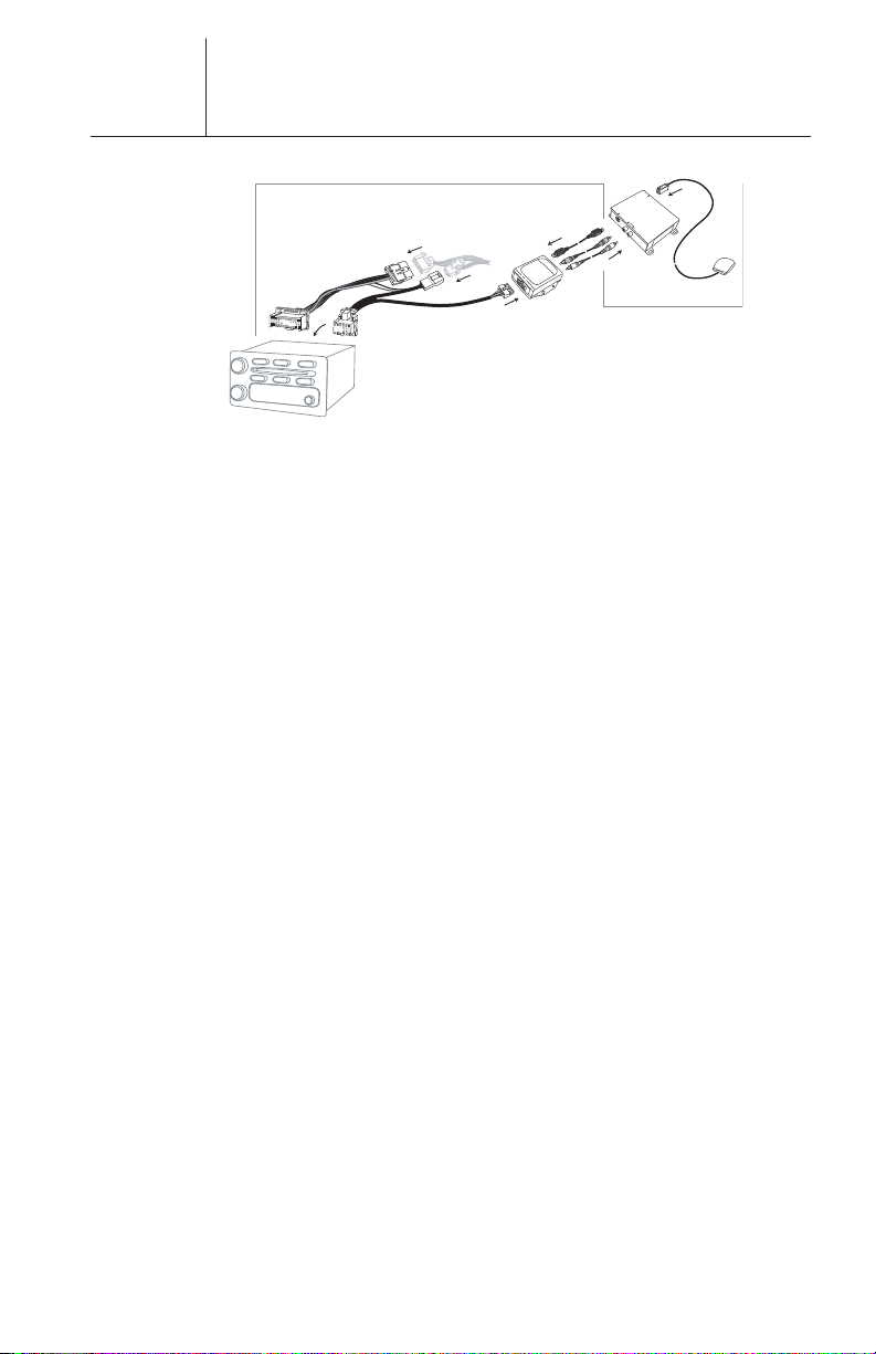
Introduction:: (continued)
Part 1:: XM Direct – Universal Tuner Box
A1 :: Micro antenna with single output
A2 :: Universal XM Tuner Box
Part 2:: XM Direct – Smart Digital Adapter
A3 :: Smart Digital Adapter – this is a small black box that
converts the XM signal to the protocol of the head unit.
W1 :: Cable harness specific to the protocol of the head unit
W2 :: Red and white audio RCA cables
W3 :: 8 pin din cable
Installation Basics::
When choosing a location to mount the components, care must
be taken not to interfere with any of the vehicles existing
systems. Good installation practices should be observed when
mounting components to avoid any vibration, movement or
rattling after installation. Components should be secured in
place with methods such as Velcro, double stick foam tape,
screws and nuts, cable ties etc. All mounting hardware and
methods are at the discretion of the installer. Cables should also
be secured in place to avoid movement. Care should be taken not
to crimp any of the cables when installing them. And special
care should be taken not to route cables on or near sharp edges
that could eventually cut into the jacket of the cable.
2
Installation Planning::
Typically the XM tuner should be located within 3 feet of the rear
of the radio due to harness and cable lengths. The antenna
should be located in an area to insure the cable will reach the
tuner l
guide XM-RVR-D-001 supplied with your XM tuner and antenna
has additional information on antenna location and installati
ation. Check this prior t
oc
o installation. The installation
Page 4

Smart Digital Adapter
TV36
Installation
The following step-by-step instructions illustrate in detail two
typical GM installations. The images on the left are for a typical SUV
installation. The images on the right are for a typical Sedan
installation.
STEP 1
REMOVE DASH BOARD TRIM BEZEL TO ACCESS RADIO
STEP 2
REMOVE MOUNTING SCREWS AND PULL OUT RADIO
3
Page 5

Smart Digital Adapter
Installation
STEP 3
UNPLUG EXISTING CONNECTORS AND ANTENNA
CABLE AND REMOVE RADIO. INSTALL LARGE AND
SMALL CONNECTORS (REMOVED FROM RADIO) INTO
HARNESS (W1) SUPPLIED WITH YOUR KIT
STEP 4
INSTALL DIRECT CONNECT ADAPTER BOX (A3) BY INSTALLING
WHITE CONNECTOR AS SHOWN.
4
Page 6

Installation
Smart Digital Adapter
STEP 5
INSTALL RED AND WHITE RCA AUDIO CABLES (W2)
AND 8 PIN MINI DIN CABLE (W3) INTO OPPOSITE SIDE
OF DIRECT CONNECT INTERFACE BOX.
STEP 6
FEED OPPOSITE ENDS OF THE RED AND WHITE RCA CABLE (W2)
AND THE 8 PIN MINI DIN CABLE (W3) TO THE SELECTED LOCATION
FOR YOUR XM TUNER (A2).
5
Page 7

Installation
Smart Digital Adaptert
STEP 7
LOCATE AND MOUNT THE ADAPTER BOX (A3) IN SUITABLE LOCATION
THAT WILL NOT INTERFERE WITH THE RADIO AND WILL NOT VIBRATE OR
RATTLE AFTER INSTALLATION. WE LOCATED THE UNIT IN A SPACE NEAR
THE AIR DUCT AND SECURED IT IN PLACE USING VELCRO.
STEP 8
AFTER THE ADAPTER BOX (A3) IS SECURE – CONNECT THE LARGE AND
SMALL CONNECTORS FROM THE HARNESS (W1) TO THE BACK OF THE
RADIO, AND CONNECT THE ANTENNA CABLE TO THE ANTENNA JACK ON
THE BACK OF THE RADIO.
6
Page 8

Installation
Smart Digital Adapter
STEP 9
CAREFULLY LOCATE THE RADIO BACK INTO POSITION. MAKE SURE
THAT THE HARNESS DOES NOT BLOCK THE RADIO UNIT OR GET CRIMPED
BY THE RADIO WHEN INSTALLING. REPLACE AND TIGHTEN THE RADIO
MOUNTING SCREWS. REPLACE THE TRIM BEZEL .
STEP 10
LOCATE AND INSTALL THE MAGNETIC MOUNT ANTENNA (A1) PER THE
INSTRUCTIONS SHOWN IN THE XM DIRECT INSTALLATION GUIDE
(XM-RVR-D-001). THE IMAGES BELOW SHOW THE ANTENNA MOUNTED
ON THE ROOF NEAR THE FRONT WINDOW.
7
STEP 11
ROUTE CABLE ACCORDINGLY TO THE LOCATION OF THE XM TUNER (A2).
Page 9

Smart Digital Adapter
Installation
STEP 12
AT THIS POINT OF THE INSTALLATION THE RED AND WHITE RCA CABLE,
THE 8 PIN MINI DIN CABLE AND THE XM ANTENNA CABLE SHOULD ALL
BE ROUTED TO THE INTENDED LOCATION OF THE XM TUNER (A2).
CONNECT THESE CABLES TO THE UNIVERSAL TUNNER BOX (A2).
STEP 13
LOCATE THE XM TUNER (A2) INTO ITS FINAL MOUNTING POSITION AND
SECURE IN PLACE WITH AN APPROPRIATE METHOD TO PREVENT
MOVEMENT AND RATTLING.
8
STEP 14
IF THE GLOVE COMPARTMENT DOOR OR ANY OTHER PART OF THE DASH
BOARD HAD BEEN REMOVED PLEASE RETURN IT TO ITS ORIGINAL
POSITION. YOUR INSTALLATION IS NOW COMPLETE. YOU MUST NOW
ACTIVATE YOUR XM TUNER.
Page 10

Smart Digital Adapter
Installation
ompletion of your installation your XM tuner will need to be
Upon c
activated. Tune the XM tuner to the Preview Channel, channel 1 and follow
instructions for activation. You can also call the toll free XM activation
number at 1-800-XM-RADIO (967-2346).
XM Satellite Radio Operation
For operation of your radio in the XM mode, please refer to the Audio
System Section of you vehicle Owner’s Manual. There you find directions on
how to use the XM features of your radio and a table which explains the
meanings of the XM text display messages.
9
Page 11

Limited Warranty
Limited Warranty TERK Technologies Corp. (TERK) warrants
this product against defects in materials or workmanship for
three (3) years from the date of purchase. During this
warranty period, this product will be replaced or repaired
without charge. This warranty does not cover any
damage due to acts of nature, commercial use, accident,
misuse, improper installation, abuse or negligence. This
warranty is only valid in the USA. Replacement as provided
under this warranty is the exclusive remedy of the consumer.
TERK shall not be liable for any incidental or consequential
damages (except for damages of up to $1,000 for damage
caused to the motor vehicle in which such product is installed,
and such $1,000 does not cover any labor costs and covers
only actual damage to goods, provided that TERK is furnished
reasonable opportunity to verify that the product was properly
installed by an appropriate installation technician) for breach
of any express or implied warranty on this product, except to
the extent that limitations of this sort are prohibited by
applicable law. To the maximum extent permitted by law,
TERK hereby disclaims all liability for personal injury arising
out of the use of this product, whether such injury is a direct
or indirect result of this product not performing as warranted.
THERE ARE NO IMPLIED WARRANTIES OF MERCHANTABILITY
OR FITNESS FOR A PARTICULAR PURCHASE EXCEPT TO THE
EXTENT THAT IMPLIED WARRANTIES OF EITHER SORT ARE
REQUIRED BY APPLICABLE LAW, AND IN SUCH CASE, EACH
WARRANTY IS LIMITED IN DURATION TO ONE YEAR.
TERK and TERK Technologies are trademarks of TERK Technologies
Corp. Commack, NY ©2004 TERK Technologies Corp. For additional
information: call 1.800.942.TERK (8375) or visit www.terk.com.
400P006
TERK is a registered trademark.
The TERK l
ogo is a tr
ademark of the TERK Technologies Corp.
 Loading...