

Page 1

Page 2
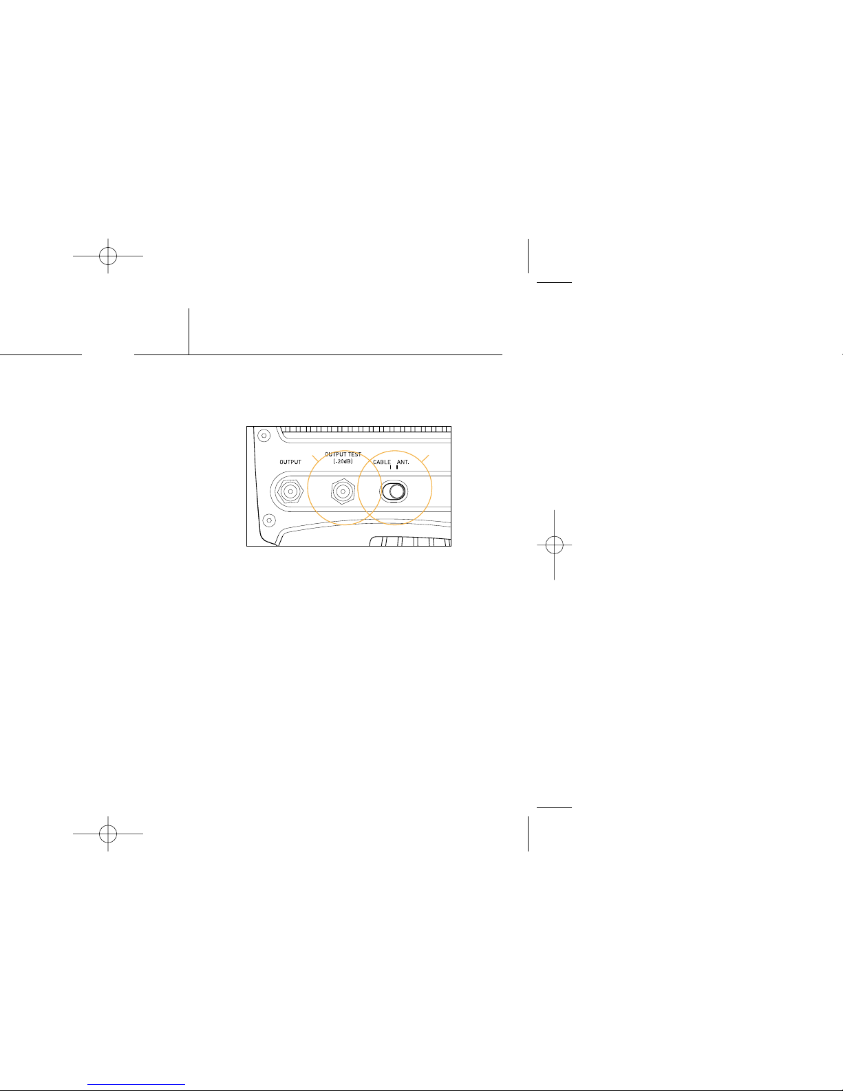
Output Test Port::
Your amplifier comes with a test output port. Simply
connect a device to the F-connector marked “OUTPUT
TEST” to utilize this feature. See fig. 2a.
Switchable Back-Channel Circuitry::
T2 amplifiers come with switchable, back-channel
circuitry. This means that your amplifier can pass signals
either one-way or bi-directionally. To select the proper
mode, choose the “CABLE” setting when using a cable
modem or any other bi-directional application. Choose
the “ANT” setting otherwise. Using the bi-directional
(CABLE) mode in conjunction with an antenna would result
in broadcasting the signal between 5 and 42 MHz, which is
a violation of FCC regulations. See fig. 2b.
Note::
Amplifiers should be placed as close to the signal source
as possible, i.e. antenna, cable input, satellite dish, etc.
2
Fig. 2
ba
50%
Page 3

Fig. 4
Fig. 5
open
locked
180˚
4
Rotate the lock 180
degrees to secure the
unit as shown in fig. 4
& fig.5. (Use a 3/16"
hex key or a flat head
screwdriver.)
Page 4

Troubleshooting::
Herringbone Patterns::
The most common cause of wavy, herringbone lines on
multiple channels is an over-driven amplifier. There are
a few causes of an over-driven amplifier:
• Too much gain in the system. If this is the case, turning
the gain dial counter-clockwise will reduce the gain and
improve the picture.
• A strong local FM signal may be present. An FM trap,
installed before the amplifier, will solve the problem.
• A strong local TV signal may be present. You may
need a tuned filter to reduce that station’s signal.
6
Page 5

 Loading...