

Page 1
Use and Care
For Customer Service
Visit Our Website At
www.audiovox.com
Product Information, Photos,
FAQ’s, Owner’s Manuals
In normal daily use, the TERK SIR6 Outdoor Home Antenna is
a rugged, high-performance antenna that does not require any
special attention.
Troubleshooting
Symptom Solutions
SIRIUS radio displays Check antenna
“Antenna Error”or connections to the
“Check Antenna”message SIRIUS receiver and
splitter if using a dual
input receiver.
SIRIUS radio displays The satellite signal maybe
“No Signal” or “Acquiring obstructed by a
Signal” message structure, trees or
located in the wrong
location. Please refer to
“Placing the Antenna”
on page 3.
Other symptoms Call Technical Support.
12 Months Limited Warranty
AUDIOVOX ELECTRONICS CORPORATION (the Company) warrants to the original retail
purchaser of this product that should this productor any part there of, under normal use
and c
onditions, be proven defective in material or workmanship within 12 months from the
date of originalpurchase, such defect(s) will be repaired or replaced with new or
reconditioned product (at the Company's option) without charge for parts and repair labor.
To obtain repair or replacement within the terms of this Warranty, the product is to be
delivered with proof of warranty coverage (e.g. datedbill of sale), specification of defect(s),
tr
ansportation prepaid, to an approved warranty station or the Company at the address
shown below.
This Warranty does not extend to the elimination of externally generated static or noise,
to costs incurred for installation, removal or reinstallation of the product, damage to
speakers, accessories, or vehicle and home electrical systems, malfunction of satellite
transmissions, repeater signal or receiver unit.
This Warranty does not apply to any product or part thereof which, in the opinion of the
Company, has suffered or been damaged through alteration, improper installation,
mishandling, misuse, neglect, accident, or by removal or defacement of the factory serial
number/bar codelabel(s). THE EXTENT OF THE COMPANY'S LIABILITY UNDER THIS
WARRANTY IS LIMITED TO THE REPAIR OR REPLACEMENT PROVIDED ABOVE AND, IN
NO EVENT, SHALL THE COMPANY'S LIABILITY EXCEED THE PURCHASE PRICE PAID BY
PURCHASER FOR THE PRODUCT.
This Warranty is in lieu of all other express warranties or liabilities. ANY IMPLIED
WARRANTIES, INCLUDING ANY IMPLIED WARRANTY OF MERCHANTABILITY, SHALL
BE LIMITED TO THE DURATION OF THIS WRITTEN WARRANTY. ANY ACTION FOR
BREACH OF ANY WARRANTY HEREUNDER INCLUDING ANY IMPLIED WARRANTY OF
MERCHANTABILITY MUST BE BROUGHT WITHIN A PERIOD OF 48 MONTHS FROM DATE
OF ORIGINAL PURCHASE. IN NO CASE SHALL THE COMPANY BE LIABLE FOR ANY
CONSEQUENTIAL ORINCIDENT
WARRANTY, EXPRESS OR IMPLIED, WHATSOEVER. No person orrepresentative is
o assume for the Company any liability other than expressed herein in
authorized t
connection with the sale of this product.
Some states do not allow limitations on how long an implied warranty lasts or the
exclusion or limitation of incidental or consequential damage so the above limitations or
exclusions may not apply to you. This Warranty gives you specific legal rights and you
may also have other rights which vary from state to state.
U.S.A. : AUDIOVOX ELECTRONICS CORPORATION, 150 MARCUS BLVD., HAUPPAUGE,
NEW YORK 11788 • 1-800-645-4994 CANADA : CALL 1-800-645-4994
FOR LOCATION OF WARRANTY STATION SERVING YOUR AREA 128-7351
AL DAMAGES FOR BREACH OF THIS OR ANY OTHER
SIR6
Owner’s Manual
About SIRIUS Satellite Radio
For more information about
SIRIUS Satellite Radio service,
visit www.Siriusradio.com
To activate your Sirius service
please call 1-888-539-7474
For customer service and
technical information::1.800.290.6650
TERK and the TERK logo are registered trademarks of AUDIOVOX Corp. 117P006B
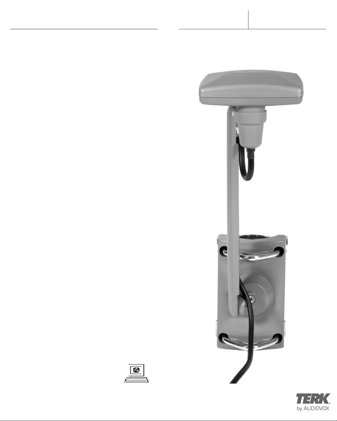
SIR6
Outdoor Satellite Radio Home Antenna
Page 2
SIR6
Table of Contents
About Installation . . . . . . . . . . . . . . . . . . . . . . . . . . . . . . . . . .2
Introduction . . . . . . . . . . . . . . . . . . . . . . . . . . . . . . . . . . . . . .2
Applications . . . . . . . . . . . . . . . . . . . . . . . . . . . . . . . . . . . . . .2
Box Contents . . . . . . . . . . . . . . . . . . . . . . . . . . . . . . . . . . . . .3
Placing the Antenna . . . . . . . . . . . . . . . . . . . . . . . . . . . . . . .3
Installation . . . . . . . . . . . . . . . . . . . . . . . . . . . . . . . . . . . . . . .4
Adjustments . . . . . . . . . . . . . . . . . . . . . . . . . . . . . . . . . . . . . .6
Cable Installation . . . . . . . . . . . . . . . . . . . . . . . . . . . . . . . . . .6
Specification . . . . . . . . . . . . . . . . . . . . . . . . . . . . . . . . . . . . . .7
Use and Care . . . . . . . . . . . . . . . . . . . . . . . . . . . . . . . . . . . . .8
Troubleshooting . . . . . . . . . . . . . . . . . . . . . . . . . . . . . . . . . . .8
Limited Warranty . . . . . . . . . . . . . . . . . . . . . . . . . . . . . . . . . .8
About SIRIUS Satellite Radio . . . . . . . . . . . . . . . . . . . . . . . .8
About Installation
Installation of antennas can require extensive experience
with a variety of mechanical and electrical procedures.
Although the instructions in this guide explain how to install
the TERK SIR6 Outdoor Satellite Radio Home Antenna in a
general sense, they do not show the exact installation
methods for every home and/or building.
IMPORTANT: If you are not comfortable performing a
complex installation, you may want to seek a professional
for installation.
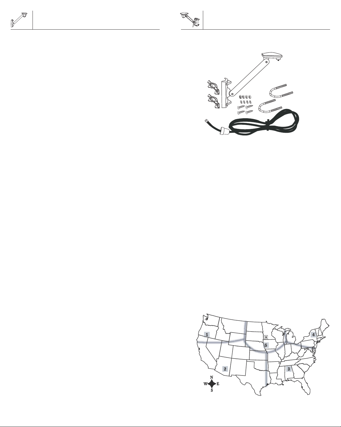
Box Contents
SIR6
Parts for the TERK SIR6 Outdoor Satellite Radio
Home Antenna
1 SIR6
1 30’ cable
2 U-bolts, 2 mount brackets, 4 washers, 4 nuts
4 (#10) screws
Verify that your TERK SIR6 package includes the
above items
Placing the Antenna
For best reception of the satellite signal, it is important to
make sure the antenna is mounted in the proper location on
your house and facing the correct direction towards the
satellites.
Introduction
The TERK SIR6 Outdoor Satellite Radio Home Antenna is a
high-performance antenna designed specifically for SIRIUS
home receivers and SIRIUS Plug & Play systems.
The package includes all the necessary mounting hardware,
to attach to a wall, roof or mast on your home or building.
Remember to save your sales receipt and this guide so both
are available for future reference.
NOTE: To achieve best SIRIUS Satellite Radio reception,
er to your SIRIUS radio owner’s manual.
ef
also r
Applications
The TERK SIR6 Outdoor Satellite Radio Home Antenna
can be installed on a variety of homes and buildings in a
number of different mounting options as shown in the
allation section on pages 4 and 5.
t
ins
Due to the paths of SIRIUS satellites over the US, the best
location for the antenna will depend on what part of the
country you live in, the orientation of your home, and the
locations of any obstructions that could prevent the satellite
signal from reaching the antenna. Use the map shown
below as a general placement guide for your antenna. The
location of the “X” on the map must be visible to the
antenna. It is recommended that, before mounting the
antenna, you hold the antenna in the desired mounting
location with the SIRIUS system set-up and on to make sure
that the system works with the antenna in that location.
ou may need t
Y
optimal mounting spot. Once this has been determined,
please proceed to installation.
o try several locations to determine the
2
3
Page 3

SIR6
or
or
Placing the Antenna
Section 1: Antenna should be mounted facing
EAST or NORTHEAST
Section 2: Antenna should be mounted facing
NORTH or NORTHEAST
Section 3: Antenna should be mounted facing
NORTH or NORTHWEST
Section 4: Antenna should be mounted facing
WEST or NORTHWEST
Section 5: Place the antenna
ONLY ON THE ROOF or MAST ON THE ROOF
NOTE: To achieve best SIRIUS Satellite Radio reception,
also refer to your SIRIUS radio owner’s manual.
Installation
Now that you have determined where to place the antenna,
you have three different mounting options. Each option is
described below.
Wall Mount
We recommend mounting the bracket horizontally if
mounting to a non-flat surface like vinyl siding.
Once the mounting location has been determined,
take a pencil and mark through the bracket, onto the
house wall, the four screw locations. Then set the
mounting br
our locations you just marked (drill bit size 3/32 is
f
recommended with #10 screws). Position the mounting
br
top two #10 screws, that are included with this package
through the mounting bracket into the wall of
the house. Then screw in the bottom two. At this point,
move onto the Adjustment section of the owner‘s manual
on page 6.
ack
et o
er the f
v
ack
et do
our pr
wn and pr
e-drill holes in the
ed holes and screw in the
e-drill
SIR6
Installation
We recommend mounting the bracket vertically on a
roof as high up as possible as shown on page 4.
The antenna should not be blocked by an obstruction like
trees or a chimney. Once you have determined your
mounting location, place the mounting bracket on that
location on the roof. Take your drill and pre-drill holes,
using a 3/32 drill bit, through the top two holes on the
mounting bracket. Screw in two of the #10 screws
included with this package, through the mounting bracket
into the pre-drilled holes in the roof. Repeat this step for
the bottom two holes. At this point, move onto the
Adjustment section of the owner’s manual on page 6.
Mast Mount
The SIR6 can be mounted to most masts. We recommend
mounting the antenna to a mast on the roof or on the mast
of a satellite TV dish. You will need the 2 U-bolts,
2 mount brackets, 4 washers and 4 nuts for this installation.
Once you have determined where on the mast you wish to
mount the antenna, place the mounting bracket in that
location against the mast. Put one of the U-bolts through
the top two holes on the mounting bracket. Take one of the
mount brackets and insert it through the two ends of the
U-bolt on the other side of the mast. Make sure the inside
of the curve of the mount bracket is towards the mast.
Using one hand to hold the mounting bracket, U-bolt and
U-bolt bracket take your other hand and place one washer
and nut on one end of the U-bolt, then turn the nut four or
five complete rotations and then place one washer and nut
on the other end of the U-bolt, turn the nut four or five
complete rotations. Make sure the mounting bracket is in
the desired l
mounting bracket is secure on the mast. Repeat these
steps for the second U-bolt. Once complete, move to the
Adjustment section of the owner’s manual on page 6.
ocation and tighten both nuts until the
4
Roof Mount
5
Page 4

SIR6
3
2
1
Adjustments
There are three areas of adjustments on the antenna,
antenna arm and mounting bracket. Please use these areas
to adjust the antenna so that it is level. You will have to
loosen the Phillips screws to rotate and adjust. Once the
adjustment has been made to the desired position,
tighten the Phillips screw. Be careful not to over tighten.
We recommend that you make the adjustments, if needed,
to each area in the order that is shown below.
Cable Installation
At this point you are ready to attach the cable.
The connectors at each end of the cable are different.
find the connector that has the threads on the inside,
then screw this connector onto the bottom of the
antenna as shown below. Screw the connector on
by hand as far as it can go. It is not necessary
to use any special tools for this
.
SIR6
Cable Installation
At this point, please determine the best way to route the
rest of the cable into your home to the SIRIUS home
receiver or SIRIUS Plug & Play system. If the included
cable is not long enough to reach your receiver,
you will have to purchase a TERK 50’ extension kit
(SIR-EXT50)-sold separately.
Specifications
Electrical Specifications
Antenna
requency: 2320 to 2332.5 MHz
F
Gain: 1 dBic, 45˚-90˚ elevation
Bandwidth: 12.5 MHz
Impedance: 50 ohms
Polarization: LHCP (Circular)
LNA
Gain: 42 dB, typical
Noise Figure : 0.7 dB, typical
Current Drain: 160 mA, maximum
Mechanical Specifications
Antenna Dimensions:
Radome: 3 1/4” x 3 1/4"
Arm Length: 8”
Mounting bracket: 4 3/4" x 2 7/8”
Material: Xenoy and AES
Once the cable is secured onto the antenna, slide the
attached rubber bott
Uncoil the remaining cable. On one side of the mounting
bracket arm remove middle insert by unscrewing the
two screws.
Once cable is inserted into the arm replace middle insert
and screw in both screws to hold in place
om onto the antenna as shown.
Cable Type: RG-58 coaxial
Cable Length: 30 feet
Connectors Antenna: SMA
Connectors Cable: SMA and SMB
Mounting Hardware
Nuts and Washers: Stainless Steel
Screws and U-Bolts: Stainless Steel
Weight including cable: 1.75 lbs
Other Specifications
Temperature: -40 °F to +185 °F, operating
Quality and Performance Tests
SIRIUS Approved: Per Specification
RX000002H-010000
TERK Approved: Per Environmental
ation TERK TRK-
Specific
10011-SIR6
6
7
 Loading...