

Page 1
SIR6
Outdoor Satellite Radio Home Antenna
SIR6
Owner’s Manual
Use and Care
In normal daily use, the TERK SIR6 Outdoor Home
Antenna is a rugged, high-performance antenna that does
not require any special attention.
Troubleshooting
Symptom Solutions
SIRIUS radio displays Check antenna
“Antenna Error”or connections to the
“Check Antenna”message SIRIUS receiver and
splitter if using a dual
input receiver.
SIRIUS radio displays The satellite signal maybe
“No Signal” or “Acquiring obstructed by a
Signal” message structure, trees or
located in the wrong
location. Please refer to
“Placing the Antenna”
on page 3.
Other symptoms Call TERK for help at
1-800-942-TERK (8375) on
any business day, between
9 a.m. and 5:30 p.m.,
EST and ask for
Technical Support.
.
TERK Technologies Corp. (TERK) warrants this product against
defects in materials or workmanship for one (1) year from the
date of purchase. During this warranty period, this product will
be replaced without charge. This warranty does not cover any
damage due to acts of nature, commercial use, accident, misuse,
abuse or negligence. This warranty is only valid in the USA.
Replacement as provided under this warranty is the exclusive
remedy of the consumer. TERK shall not be liable for any
incidental or consequential damages for breach of any express or
implied warranty on this product, except to the extent that
limitations of this sort are prohibited by applicable law.
THERE ARE NO IMPLIED WARRANTIES OF MERCHANTABILITY
OR FITNESS FOR A PARTICULAR PURCHASE EXCEPT TO THE
EXTENT THAT IMPLIED WARRANTIES OF EITHER SORT ARE
REQUIRED BY APPLICABLE LAW, AND IN SUCH CASE,
EACH WARRANTY IS LIMITED IN DURATION TO ONE YEAR.
About SIRIUS Satellite Radio
For more information about SIRIUS Satellite Radio service,
visit www.Siriusradio.com
To activate your Sirius service
please call 1-888-539-7474
Limited Warranty
Use and Care
For more information, visit www.terk.com or
for technical support, call 1.800.942.TERK(8375) 117P006A
TERK is a registered trademark. The TERK Logo is a trademark of TERK Technologies Corp.
T0365-SIR6-R1-OM.qxp 3/19/04 3:40 PM Page C4
Page 2
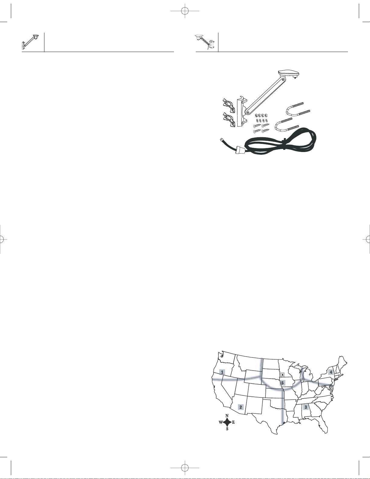
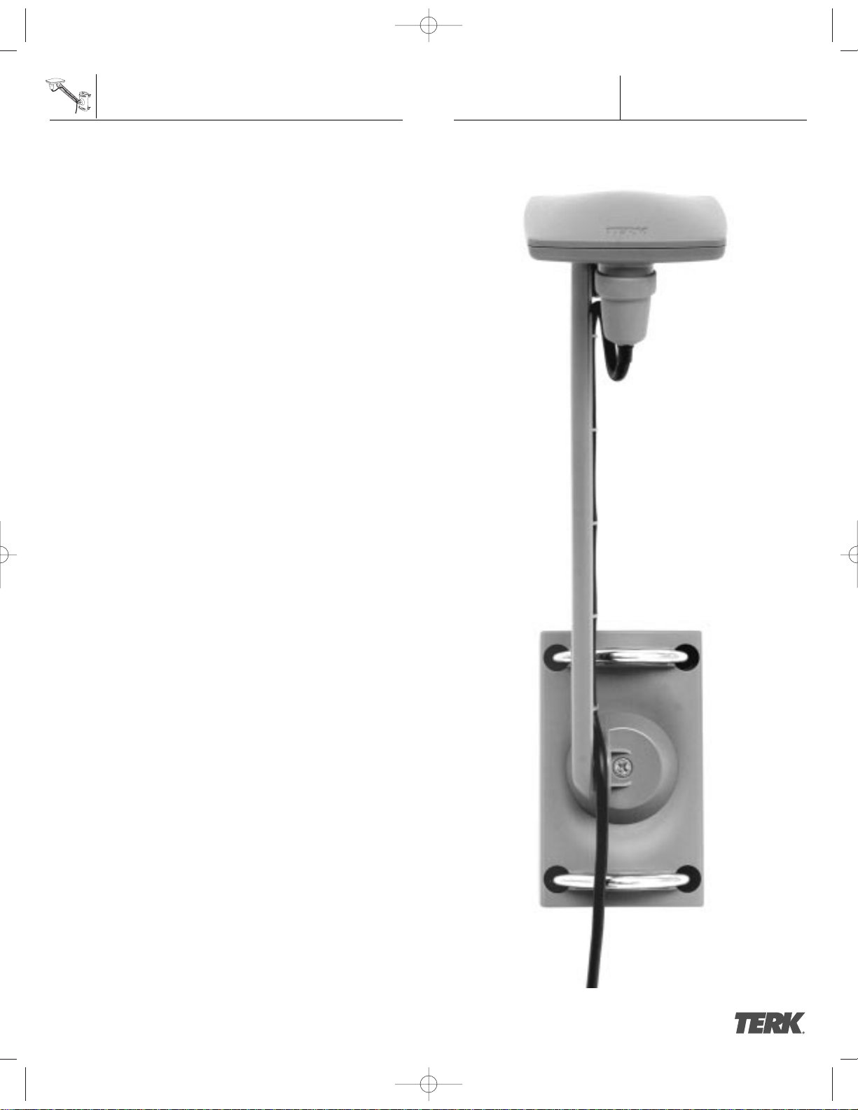
Parts for the TERK SIR6 Outdoor Satellite Radio
Home Antenna
1 SIR6
1 30’ cable
2 U-bolts, 2 mount brackets, 4 washers, 4 nuts
4 (#10) screws
Verify that your TERK SIR6 package includes the
above items
For best reception of the satellite signal, it is important to
make sure the antenna is mounted in the proper location on
your house and facing the correct direction towards the
satellites.
Due to the paths of SIRIUS satellites over the US, the best
location for the antenna will depend on what part of the
country you live in, the orientation of your home, and the
locations of any obstructions that could prevent the satellite
signal from reaching the antenna. Use the map shown
below as a general placement guide for your antenna. The
location of the “X” on the map must be visible to the
antenna. It is recommended that, before mounting the
antenna, you hold the antenna in the desired mounting
location with the SIRIUS system set-up and on to make sure
that the system works with the antenna in that location.
You may need to try several locations to determine the
optimal mounting spot. Once this has been determined,
please proceed to installation. When facing the antenna
towards the satellites, face the side of the antenna that has
the TERK logo on it; this is the front of the antenna.
Placing the Antenna
About Installation . . . . . . . . . . . . . . . . . . . . . . . . . . . . . . . .2
Introduction . . . . . . . . . . . . . . . . . . . . . . . . . . . . . . . . . . . . .2
Applications . . . . . . . . . . . . . . . . . . . . . . . . . . . . . . . . . . . .2
Box Contents . . . . . . . . . . . . . . . . . . . . . . . . . . . . . . . . . . . .3
Placing the Antenna . . . . . . . . . . . . . . . . . . . . . . . . . . . . . .3
Installation . . . . . . . . . . . . . . . . . . . . . . . . . . . . . . . . . . . . .4
Adjustments . . . . . . . . . . . . . . . . . . . . . . . . . . . . . . . . . . . .6
Cable Installation . . . . . . . . . . . . . . . . . . . . . . . . . . . . . . . .6
Specification . . . . . . . . . . . . . . . . . . . . . . . . . . . . . . . . . . . .7
Use and Care . . . . . . . . . . . . . . . . . . . . . . . . . . . . . . . . . . .8
Troubleshooting . . . . . . . . . . . . . . . . . . . . . . . . . . . . . . . . .8
Limited Warranty . . . . . . . . . . . . . . . . . . . . . . . . . . . . . . . .8
About SIRIUS Satellite Radio . . . . . . . . . . . . . . . . . . . . . . .8
About Installation
Installation of antennas can require extensive experience
with a variety of mechanical and electrical procedures.
Although the instructions in this guide explain how to install
the TERK SIR6 Outdoor Satellite Radio Home Antenna in a
general sense, they do not show the exact installation
methods for every home and/or building.
IMPORTANT: If you are not comfortable performing a
complex installation, you may want to seek a professional
for installation.
The TERK SIR6 Outdoor Satellite Radio Home Antenna is a
high-performance antenna designed specifically for SIRIUS
home receivers and SIRIUS Plug & Play systems.
The package includes all the necessary mounting hardware,
to attach to a wall, roof or mast on your home or building.
Remember to save your sales receipt and this guide so both
are available for future reference.
NOTE: To achieve best SIRIUS Satellite Radio reception,
also refer to your SIRIUS radio owner’s manual.
The TERK SIR6 Outdoor Satellite Radio Home Antenna
can be installed on a variety of homes and buildings in a
number of different mounting options as shown in the
installation section on pages 4 and 5.
Box Contents
SIR6
3
Table of Contents
SIR6
2
Introduction
Applications
T0365-SIR6-R1-OM.qxp 3/19/04 3:40 PM Page C2
Page 3

We recommend mounting the bracket vertically on a
roof as high up as possible as shown on page 4.
The antenna should not be blocked by an obstruction like
trees or a chimney. Once you have determined your
mounting location, place the mounting bracket on that
location on the roof. Take your drill and pre-drill holes,
using a 3/32 drill bit, through the top two holes on the
mounting bracket. Screw in two of the #10 screws
included with this package, through the mounting bracket
into the pre-drilled holes in the roof. Repeat this step for
the bottom two holes. At this point, move onto the
Adjustment section of the owner’s manual on page 6.
Mast Mount
The SIR6 can be mounted to most masts. We recommend
mounting the antenna to a mast on the roof or on the mast
of a satellite TV dish. You will need the 2 U-bolts,
2 mount brackets, 4 washers and 4 nuts for this installation.
Once you have determined where on the mast you wish to
mount the antenna, place the mounting bracket in that
location against the mast. Put one of the U-bolts through
the top two holes on the mounting bracket. Take one of the
mount brackets and insert it through the two ends of the
U-bolt on the other side of the mast. Make sure the inside
of the curve of the mount bracket is towards the mast.
Using one hand to hold the mounting bracket, U-bolt and
U-bolt bracket take your other hand and place one washer
and nut on one end of the U-bolt, then turn the nut four or
five complete rotations and then place one washer and nut
on the other end of the U-bolt, turn the nut four or five
complete rotations. Make sure the mounting bracket is in
the desired location and tighten both nuts until the
mounting bracket is secure on the mast. Repeat these
steps for the second U-bolt. Once complete, move to the
Adjustment section of the owner’s manual on page 6.
Section 1: Antenna should be mounted facing
EAST or NORTHEAST
Section 2: Antenna should be mounted facing
NORTH or NORTHEAST
Section 3: Antenna should be mounted facing
NORTH or NORTHWEST
Section 4: Antenna should be mounted facing
WEST or NORTHWEST
Section 5: Place the antenna
ONLY ON THE ROOF or MAST ON THE ROOF
NOTE: To achieve best SIRIUS Satellite Radio reception,
also refer to your SIRIUS radio owner’s manual.
Now that you have determined where to place the antenna,
you have three different mounting options. Each option is
described below.
Wall Mount
We recommend mounting the bracket horizontally if
mounting to a non-flat surface like vinyl siding.
Once the mounting location has been determined,
take a pencil and mark through the bracket, onto the
house wall, the four screw locations. Then set the
mounting bracket down and pre-drill holes in the
four locations you just marked (drill bit size 3/32 is
recommended with #10 screws). Position the mounting
bracket over the four pre-drilled holes and screw in the
top two #10 screws, that are included with this package
through the mounting bracket into the wall of
the house. Then screw in the bottom two. At this point,
move onto the Adjustment section of the owner‘s manual
on page 6.
Roof Mount
Installation
SIR6
5
Placing the Antenna
SIR6
4
Installation
T0365-SIR6-R1-OM.qxp 3/19/04 3:40 PM Page C4
or
or
Page 4

At this point, please determine the best way to route the
rest of the cable into your home to the SIRIUS home
receiver or SIRIUS Plug & Play system. If the included
cable is not long enough to reach your receiver,
you will have to purchase a TERK 50’ extension kit
(SIR-EXT50)-sold separately.
Electrical Specifications
Antenna
Frequency: 2320 to 2332.5 MHz
Gain: 1 dBic, 45˚-90˚ elevation
Bandwidth: 12.5 MHz
Impedance: 50 ohms
Polarization: LHCP (Circular)
LNA
Gain: 42 dB, typical
Noise Figure : 0.7 dB, typical
Current Drain: 160 mA, maximum
Mechanical Specifications
Antenna Dimensions:
Radome: 3 1/4” x 3 1/4"
Arm Length: 8”
Mounting bracket: 4 3/4" x 2 7/8”
Material: Xenoy and AES
Cable Type: RG-58 coaxial
Cable Length: 30 feet
Connectors Antenna: SMA
Connectors Cable: SMA and SMB
Mounting Hardware
Nuts and Washers: Stainless Steel
Screws and U-Bolts: Stainless Steel
Weight including cable: 1.75 lbs
Other Specifications
Temperature: -40 °F to +185 °F, operating
Quality and Performance Tests
SIRIUS Approved: Per Specification
RX000002H-010000
TERK Approved: Per Environmental
Specification TERK TRK10011-SIR6
SIR6
7
Adjustments
There are three areas of adjustments on the antenna,
antenna arm and mounting bracket. Please use these areas
to adjust the antenna so that it is level. You will have to
loosen the Phillips screws to rotate and adjust. Once the
adjustment has been made to the desired position,
tighten the Phillips screw. Be careful not to over tighten.
We recommend that you make the adjustments, if needed,
to each area in the order that is shown below.
At this point you are ready to attach the cable.
The connectors at each end of the cable are different.
find the connector that has the threads on the inside,
then screw this connector onto the bottom of the
antenna as shown below. Screw the connector on
by hand as far as it can go. It is not necessary
to use any special tools for this.
Once the cable is secured onto the antenna, slide the
attached rubber bottom onto the antenna as shown.
Uncoil the remaining cable. On one side of the mounting
bracket arm is a cable track with five cable clips.
For improved cable routing, snap the cable into the
cable clips as shown below.
SIR6
6
Cable Installation
Cable Installation
Specifications
T0365-SIR6-R1-OM.qxp 3/19/04 3:40 PM Page C6
3
2
1
 Loading...