

A Maxim Integrated Products Brand
Flash Programmer
Model TFP2
USER’S MANUAL
Revision 2.3
August 8, 2011

Flash Programmer Model TFP2 User’ s M anu al
Revision History
Revision Date Description
1.0 4/27/2007 Initial release.
2.1 2/4/2009 Added note for ICE enabl e pin.
2.2 10/20/2010 Added Order Number.
2.3 8/8/2011 Added troubleshooting tips.
Replaced TFP2 photos.
Maxim cannot assume responsibility for use of any circuitry other than circuitry entirely embodied in a Maxim product. No circuit
patent licenses are implied. Maxim reserves the right to change the circuitry and specifications without notice at any time.
Maxim Int egrated Products, 120 San Gabriel Drive, Sunnyvale, CA 94086 408-737- 7600
2011 Maxim Integrated Products Maxim is a registered trademark of Maxim Integrated Products.

Flash Programmer Model TFP2 User’s Manual
Table of Contents
1 GETTING STARTED......................................................................................................................... 5
1.1 General ...................................................................................................................................... 5
1.2 Safety and ESD Notes ............................................................................................................... 5
1.3 Kit Contents .............................................................................................................................. 6
1.4 Compatibility ............................................................................................................................. 6
1.5 Sugges t e d Equipment not Included ......................................................................................... 6
2 PC USER INTERFACE ..................................................................................................................... 7
2.1 TFP2 CHKSUM.EXE Utility ........................................................................................................ 7
2.2 TFP2 EEPROM Download ....................................................................................................... 11
2.3 TARGET FLASH Memory Programming ................................................................................ 13
2.4 Previously Programmed Device Verification ......................................................................... 14
2.5 Device Status Check ............................................................................................................... 15
2.6 Code Or Parameter Update ..................................................................................................... 15
2.7 Parameter Preservation P rog ramming................................................................................... 15
3 TARGET C OD E IN I TIALIZATION ................................................................................................... 19
3.1 Power Supply CONNECTION .................................................................................................. 20
3.2 RS-232 Serial Connection ....................................................................................................... 20
3.3 Serial Connection S etup ......................................................................................................... 20
4 TARGET FLASH MEMORY PROGRAMMING ................................................................................ 21
4.1 Standalone Programming ....................................................................................................... 23
4.2 PC User Interface Programming............................................................................................. 24
4.3 ATE Factory Automation Prog rammin g ................................................................................. 24
5 BOOT LOA D E R .............................................................................................................................. 27
5.1 Boot Loader Operation ........................................................................................................... 27
6 STATUS INDICATIONS .................................................................................................................. 29
6.1 Normal Operation .................................................................................................................... 29
6.2 Error Conditions ..................................................................................................................... 29
7 TFP2 HARDWARE S P E CIFICATIONS ........................................................................................... 31
8 TROUBLESHOOTING .................................................................................................................... 33
8.1 Communication Errors ........................................................................................................... 33
8.2 Verification Erro rs ................................................................................................................... 34
8.3 Cable Issues and Marginal Timing ......................................................................................... 34
8.4 File Load Errors ...................................................................................................................... 34
9 ORDERING INFORMATION ........................................................................................................... 35
Revision 2.3 3 of 36

Flash Programmer Model TFP2 User’ s M anu al
Figures
Figure 2-1: CHKSUM.EXE Hex File Processing ....................................................................................... 7
Figure 2-2: CHKSUM.EXE W arni ng Displ ay ............................................................................................. 8
Figure 2-3: TFP2 Power-Up Information Display ...................................................................................... 8
Figure 2-4: TFP2 Help Menu.................................................................................................................... 9
Figure 2-5: TFP2 Intel Hex File Download to Internal EEPROM Command ............................................ 11
Figure 2-6: TFP2 Select Target Intel Hex File ........................................................................................ 11
Figure 2-7: TFP2 Download in Pr ogr ess ................................................................................................ 11
Figure 2-8: TFP2 Download Complete ................................................................................................... 12
Figure 2-9: TFP2 Download Fail due to Incorrect Memory Size Setting .................................................. 12
Figure 2-10: TFP2 Target Mass Erase and Program Command ............................................................. 13
Figure 2-11: Existing Device’s Security Bit Set ....................................................................................... 13
Figure 2-12: Programming Overrides Security Bit .................................................................................. 13
Figure 2-13: Previousl y P r ogr ammed Device Check .............................................................................. 14
Figure 2-14: Previousl y P r ogr ammed Device Check with Security Bit Set............................................... 14
Figure 2-15: Device Check sum and Sec ur ity Bit Status .......................................................................... 15
Figure 2-16: Device Check sum and Sec ur ity Bit Status with Security Bit Set .......................................... 15
Figure 2-17: Parameter Mode Selection ................................................................................................. 16
Figure 2-18: Parameter Mode Status ..................................................................................................... 17
Figure 3-1: Memory Size Configuration .................................................................................................. 19
Figure 3-2: TFP2 RS-232 Connection to PC .......................................................................................... 19
Figure 3-3: Port Speed, Port Bit S etup and Fl ow Control ........................................................................ 20
Figure 4-1: Target-LS Connection .......................................................................................................... 21
Figure 4-2: Target-HS Connection ......................................................................................................... 21
Figure 4-3: Target-LS Connector Pin Locations (looking at TFP2 endplate) ............................................ 22
Figure 4-4: Target-HS Connector Pin Locations (l ook ing at TFP2 endplate) ........................................... 23
Figure 4-5: Standalone Configuration (shown with Target-HS cable) ...................................................... 23
Figure 4-6: PC User Interf ac e Configuration (shown with Target -HS cable for example) ......................... 24
Figure 4-7: ATE Connect or Pin Locations (looking at TFP2 endplate) .................................................... 25
Figure 4-8: Program Flow Chart ............................................................................................................. 26
Figure 5-1: TFP2 Reprogram TFP 2 Program M em or y ............................................................................ 27
Figure 5-2: TFP2 Boot Completion ......................................................................................................... 28
Tables
Table 2-1: CHKSUM Utility Addresses ..................................................................................................... 9
Table 2-2: CHKSUM Utility Out put Dat a ................................................................................................. 10
Table 2-3: CHKSUM Utility Data Dependency ........................................................................................ 10
Table 2-4: Paramet er Space A ddr ess Location ...................................................................................... 16
Table 3-1: RS-232 Strai ght Cable Connections ...................................................................................... 20
Table 4-1: Target-LS Connector Pins ..................................................................................................... 22
Table 4-2: Target-HS Connector Pins .................................................................................................... 23
Table 4-3: ATE Connector Pi ns ............................................................................................................. 25
Table 4-4: ATE Connector Pi n Input Voltage Thresholds ........................................................................ 25
Table 4-5: ATE Connector Pi n Output V oltage Levels ............................................................................ 25
Revision 2.3 4 of 36

1
Flash Programmer Model TFP2 User’s Manual
1 GETTING STARTED
1.1 GENERAL
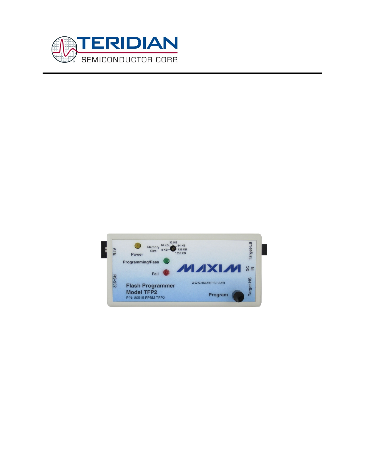
The TFP2 Flash Programmer, Model TFP 2 provides a stand-alone, FLASH memory programming tool for
Teridian Semic onduc tor’s embedded controller s. The TFP 2 facilitates FLASH programmi ng in a
manufacturing production environment requiring minimum ancillary equipment. Once the TFP2 has been
initializ ed with the target’s program code, the target’s FLASH memory can be programm ed either
manually vi a operator push button, or controlled vi a a factory automation computer (ATE).
The target’s program c ode is stored in a standard 32-pin PLCC 256 KB x 8 Flash PROM (EEPROM). A
RS-232 interface is provided for connection to a PC allowing for downloading of the target’s program
code to the TFP2’s internal E E P ROM. Thi s downloadi ng utility along wit h target programming and
additional status information is provided v ia a simple text based user interface.
The TFP2 supports target flash memory sizes of: 8KB, 16KB, 32KB, 64KB , 128KB, and 256KB.
Once the TFP2’s internal E E P ROM is programmed, the PC may be removed for standalone operation.
Standalone operat ion only performs the target F LASH mem ory progr ammi ng. Once programmed, the
target’s FLASH mem ory contents are verified and a PASS or FAIL indication is reported. The TFP2 front
panel incorpor ates two status LEDs. These status indications are also provided at the ATE connector
and displayed by the P C User Interface.
Two target connector s are prov ided to facilitate custom target c onnec tions. The standard ADM-51 ribbon
cable connector is provided along with a discrete wire connector . The discrete wire connector
accommodates low cost, custom cable harnesses. These two cable connector interfaces are hardwired
together and are not two separate interfaces.
1.2 SAFETY AND ESD NOTES
Standard ESD handli ng pr ec autions should be employed whenev er handli ng electronic equipment. The
TFP2 Flash Programmer utilizes ESD protection devices on its cable interfaces. Potential equipment
damage and/or malfunction is possible if work surf ac e groundi ng pr oc edur es are not incorporated.
Revision 2.3 5 of 36
The TFP2 ESD protection devices do not protect the target’s hardware. Correct
handling procedures and proper work area grounding minimizes damage to all
equipment!

Flash Programmer Model TFP2 User’ s M anu al
1.3 KIT CONTENTS
Model TFP2 Flash Programmer
5VDC/1,000mA universal wall transform er with 2.5mm plug
Serial cabl e, DB9, Male/F em ale, straight cable, 2m length (Digi-Key AE1020-ND)
ATE cable housing and crimp pins
Target-LS cable housing and c r im p pins
CHKSUM.EXE Utilit y Di sket te or CD-ROM
Model TFP2 User Manual
TFP2 Quick Start Guide
1.4 COMPATIBILITY
This manual applies to the following hardware and software rev isions:
TFP2 fir mw a r e revision 1.53 or later
TFP2 hardware revi si on 1
1.5 SUGGESTED EQUIPMENT NOT INCLUDED
For use with optional text user interface operati on (terminal emulation soft ware):
PC w/ MS-Windows
(COM port) via DB9 connector
versions XT, ME, 2000, or Windows 7, equi pped with RS-232 port
Revision 2.3 6 of 36
2
Flash Programmer Model TFP2 User’s Manual
2 PC USER INTERFACE
2.1 TFP2 CHKSUM.EXE UTILITY
Prior to downloading the target’s hex file to the TFP2, the target’s hex file must be preprocessed using the CHKS UM.E XE uti li t y pro vid ed with the enclosed diskette. A hex file
not processed with CHKSUM.EXE will resu lt in incomplete programming of the target’s
FLASH memory. The target’s code must be of the Extended Intel ASCII HEX-80 format for
processing by CHKSUM.EXE.
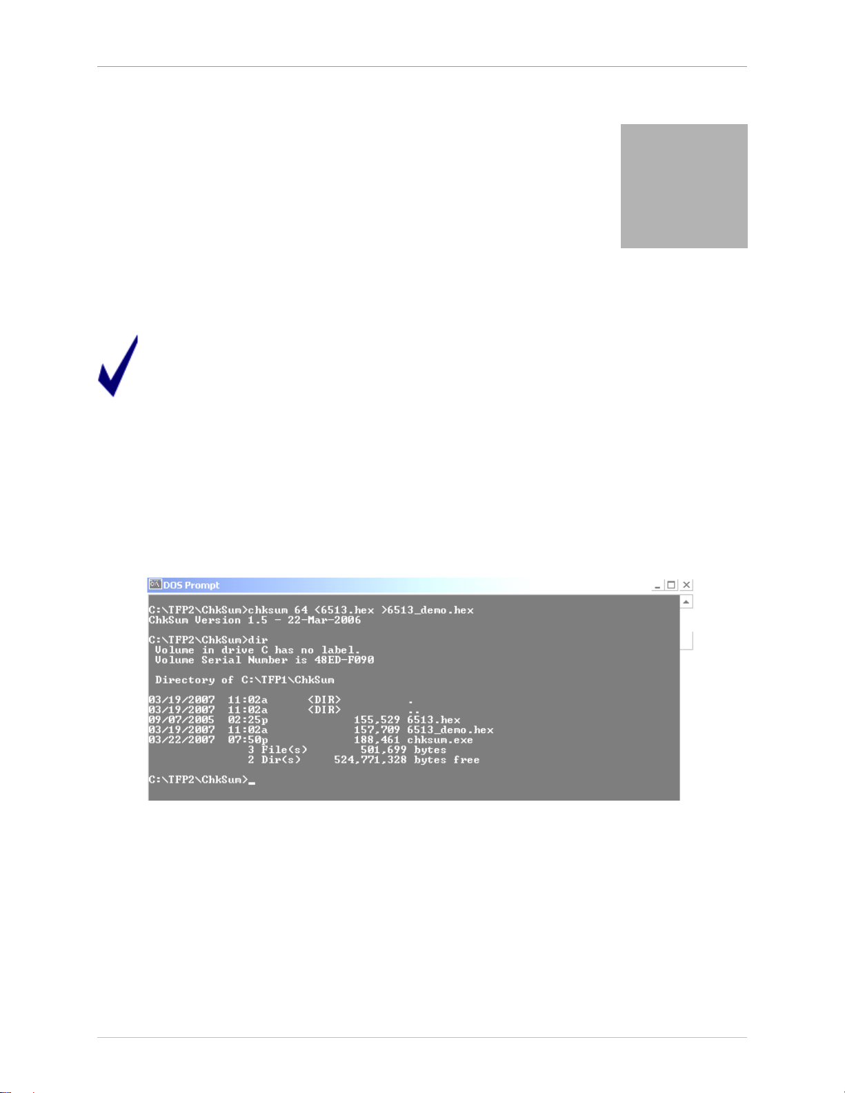
From the DOS Command prompt, inv ok e CHKSUM.EXE as follows:
chksum kb <infile.hex >outfile.hex where:
kb = desired file siz e, Mem or y Size S witch setting to be used during TFP2 downloading and
target programmi ng
infile = t ar get code hex file to be processed
outfile = processed t ar get code hex file to be downloaded to TFP2
The following fi gur e shows a typical invocation of CHKSUM.EXE:
Figure 2-1: CHKSUM.EXE Hex File Processing
The purpose of the CHKSUM utilit y is to or ganize the individual hex records into a contiguous “sequential
address increasing” structure. Some complier s produce non-sequ ential hex files. T he TFP2 assumes a
sequential file struct ur e. A non-sequential hex file downloaded to the TFP2 resul ts in missing bytes (the
missing bytes are the out -of-sequence hex records) in the target flash memor y (when the target is then
programmed wit h the TFP 2).
The CHKSUM.EXE utility m ay or may not ov er write the last four bytes of the downloaded target hex file
depending on whether these l oc ations are used or not.
Revision 2.3 7 of 36
Flash Programmer Model TFP2 User’ s M anu al
The following cases apply to using the CHKSUM.EXE utility:
1. If the last four byt es of the t ar get hex file are unused (0xFF), the CHKSUM.EXE uti lity will insert
its own calculated t wo byte CRC and two byte checksum.
2. If any of the last four byt es of the t ar get hex file are non-0xFF values, the CHKSUM.EXE utility
will NOT overwrite the four original values.
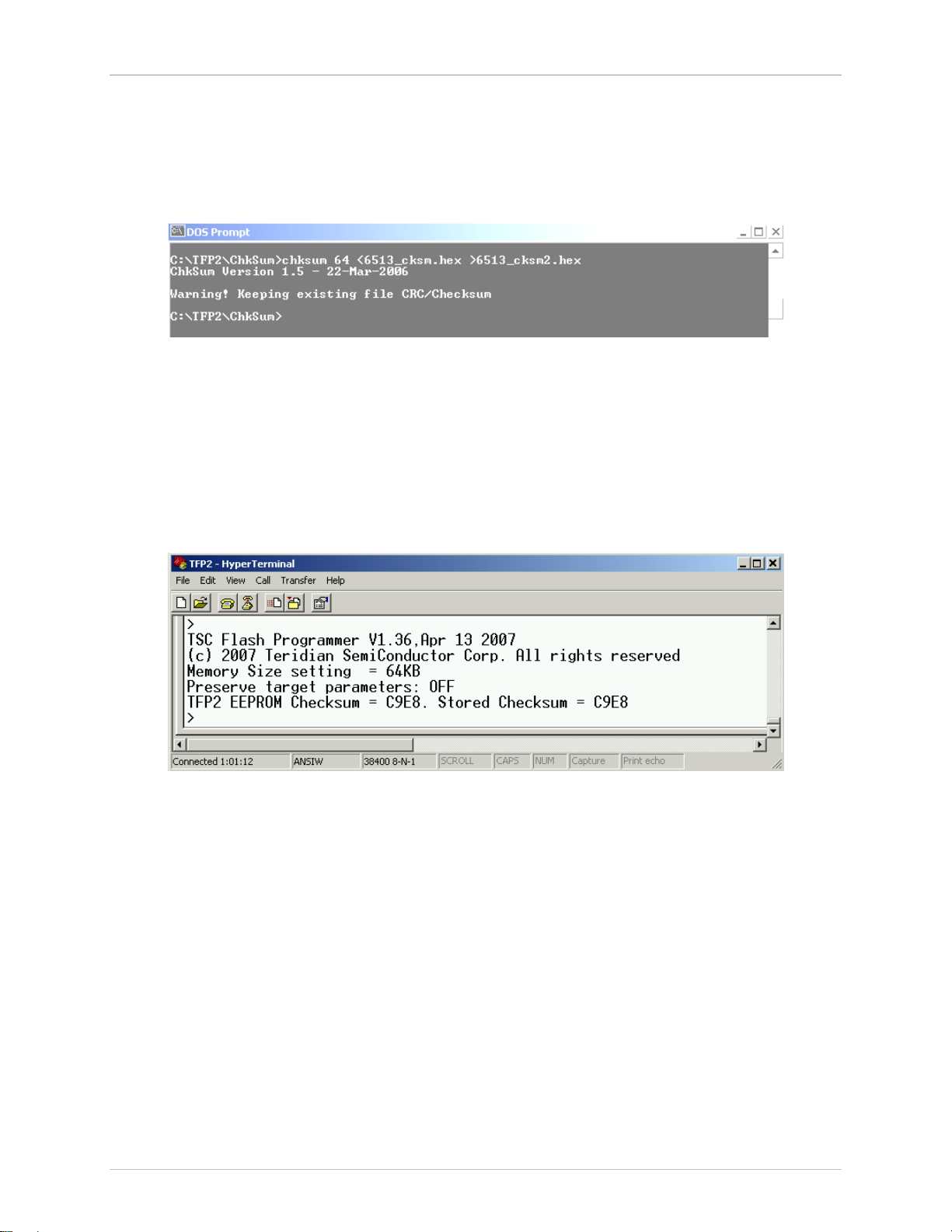
The CHKSUM.EXE utility displ ay s the following warning when it encounters non-0xFF values:
Figure 2-2: CHKSUM.EXE Warning Display
When programmi ng the target FLAS H m em ory, these last four bytes of the target hex file are transf er r ed
intact. Either the CHKS UM.E XE calc ulated CRC and checksum bytes are copi ed or the ori ginal target’s
hex data are copied. If the last t wo bytes of the target hex file are 0xFF (CHKSUM not used), t he TF P 2
overwrites the last two 0xFF bytes with its calculated checksum dur ing the Hyper-Terminal file Download
operation.
With HyperTerminal configured for serial COM port, 38400 baud, 1 stop bit, no parity, XON/X OF F ( refer to
Section 3.3 for serial communic ation setup information) the following inform ation is displayed upon
applying power to t he TFP2. Any generic termi nal emulation program will work. Howev er , the target hex
file download instr uc tions presented apply to HyperTerminal.
Figure 2-3: TF P 2 Powe r -Up Information Display
The Memory Size Switc h setting and the checksum of the current target fil e stor ed in the TFP2’s internal
EEPROM are displayed. An “I nv alid M em or y Size setting” m essage appears if the Memory Size Switch is
set to one of the invalid positions. Rotate the Memory Size Switch to a proper setting and re-apply power
to the TFP2 to update the Memory Siz e setting.
If the target hex file has non-FF values in any of the last four bytes, t he abov e power-on screen m ay
display a “TFP2 EEPROM verification er r or .” message. The displayed “TFP2 EEPROM Checksum =”
value and “Stored Checksum =” value will be different. This occurs when the stored check sum value
(from user’s target fi le) is derived from a different c hec ksum c alc ulation from what the TFP2 uses.
Therefore, the TFP 2 c annot confirm the EEPROM’s contents. Howev er, the chec k sum verification error
will not prevent the TF P 2 from programming a target board. The “TFP2 EEPROM Checksum =” value is
recalcul ated upon every power-on or system reset. Manual verification of the EEPROM’s contents
requires compari ng the TFP2 EEPROM Checksum value derived after the file download to subsequent
power-on recalculated checksum values. See Figure 2-8 for an example of a display ed c hec k sum value
after a file download.
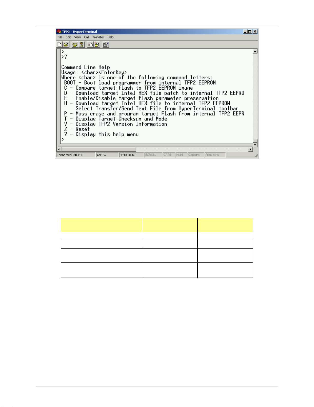
Upon pressing the “Ent er ” key , the “>” charac ter is displayed indicating the TFP2 acknowledges the PC’s
keyboard. Typing “ ?” followed by the “ E nter” key displays the Help Menu.
Revision 2.3 8 of 36
Checksum
Flash Programmer Model TFP2 User’s Manual
Figure 2-4: TFP2 Help M enu
Commands C, E, T, V, Z and ? are single keystroke events (no further user acti on requi r ed until the TFP2
completes the int ended task). The D, H and P commands require additional user action and are
described in Section 2.6, Section 2.2, and Section 2.3, respectively. The BOOT command is a special
user action and is descri bed in Section 5.
The following t ables show the results of the last two words of the hex file after usi ng CHKS UM and after
downloading and program m ing using the TFP2. The referenced addresses assume use of a 64KB flash
memory configuration.
Initial Hex File Dat a File Address
0xFFFC
Hex Fi le with 0xF F 0xFFFF 0xFFFF
Hex File with non-0xFF CRC UserData 0xFFFF
Hex File with non-0xFF
Hex File with non-0xFF CRC
and non-0xFF Checksum
Table 2-1: CHKSUM Utility Addresses
Upon executing CHKS UM, the fi r st line displayed contains the CHKS UM versi on. Table 2-2 shows the
results of processing the above hex files with CHKSUM.
0xFFFF UserData
UserData UserData
File Address
0xFFFE
Revision 2.3 9 of 36

Checksum
Target
Target
Program Verify Passes
Power-Up Verify Passes
Program Verify Passes
Power-Up Verify Passes
Program Verify Passes
Program Verify Passes
Power-Up Verify Fails
Program Verify Passes
Power-Up Verify Fails
Program Verify Passes
Power-Up Verify Fails
Power-Up Verify Fails
Flash Programmer Model TFP2 User’ s M anu al
Hex File Data after Using
CHKSUM
File Address
0xFFFC
CHKSUM v1.5
File Address
0xFFFE
Hex Fi le with 0xF F 0xFFFF Teridian
Checksum
Hex File with non-0xFF CRC UserData Teridian
Checksum
Hex File with non-0xFF
0xFFFF UserData
Hex File with non-0xFF CRC
UserData UserData
and non-0xFF Checksum
Table 2-2: CHKSUM Utility Output Data
The TFP2 Download Verify and P ower-Up Verify expects to read the Teridi an c hec k sum. For the
following ex am ples shown below, a Do wnload V er ify fail and Power-Up Verify f ail occurs because the
user data is preserv ed ( r ather than over-writing with the Teridi an v alues). A Download Verify fail and
Power-Up Verify f ail does not pr ev ent correct target memory programming ( these messages are
informati onal only). The Teridian checksum insertion (over-writing) m ay only occ ur when using CHKS UM
or during the TFP2 download (if 0xFF values are encountered).
The TFP2 programs into t he target memory what was previously downloaded (once downloaded, the l ast
two words do not change during pr ogr amming). The TFP2 then verifies the target memory to its internal
memory resulting in the correct PASS indication ev en when user data is present.
Target Data after Using TFP2
Hex Fi le with 0xF F 0xFFFF
Hex File with 0xFF after CHKSUM v 1.5 0xFFFF
Address
0xFFFC
Address
0xFFFE
Teridian
Checksum
Teridian
Checksum
Comments
Download Verify P asses
Download Verify P asses
Hex File with non-0xFF CRC UserData
Hex File with non-0xFF CRC after
CHKSUM v1.5 (includes UserData into its
Hex File with non-0xFF Check sum 0xFFFF UserData
Hex File with non-0xFF Check sum af ter
Hex File with non-0xFF CRC and non-0xFF
Hex File with non-0xFF CRC and non-0xFF
Checksum after CHKSUM v1. 5
Revision 2.3 10 of 36
Checksum)
CHKSUM v1.5
Checksum
Teridian
Checksum
UserData
Teridian
Checksum
0xFFFF UserData
UserData UserData
UserData
UserData
Table 2-3: CHKSUM Utility Data Dependency
Download Verify Fails
Power-Up Verify Fails
Program Verify Passes
Download Verify P asses
Power-Up Verify Passes
Download Verify Fails
Download Verify Fails
Download Verify Fails
Program Verify Passes
Download Verify Fails
Flash Programmer Model TFP2 User’s Manual
2.2 TFP2 EEPROM DOWNLOAD
Transfer of the target’s code from a PC to the TFP2 begins with the “H” command. The target code file
must have been preprocessed using the CHKSUM.EXE utility pr ov ided on the enclosed diskette. Refer
to Section 2.1 for instructions on using CHKSUM.EXE. Use of any other format results in m alfunction and
download checksum er r or s.
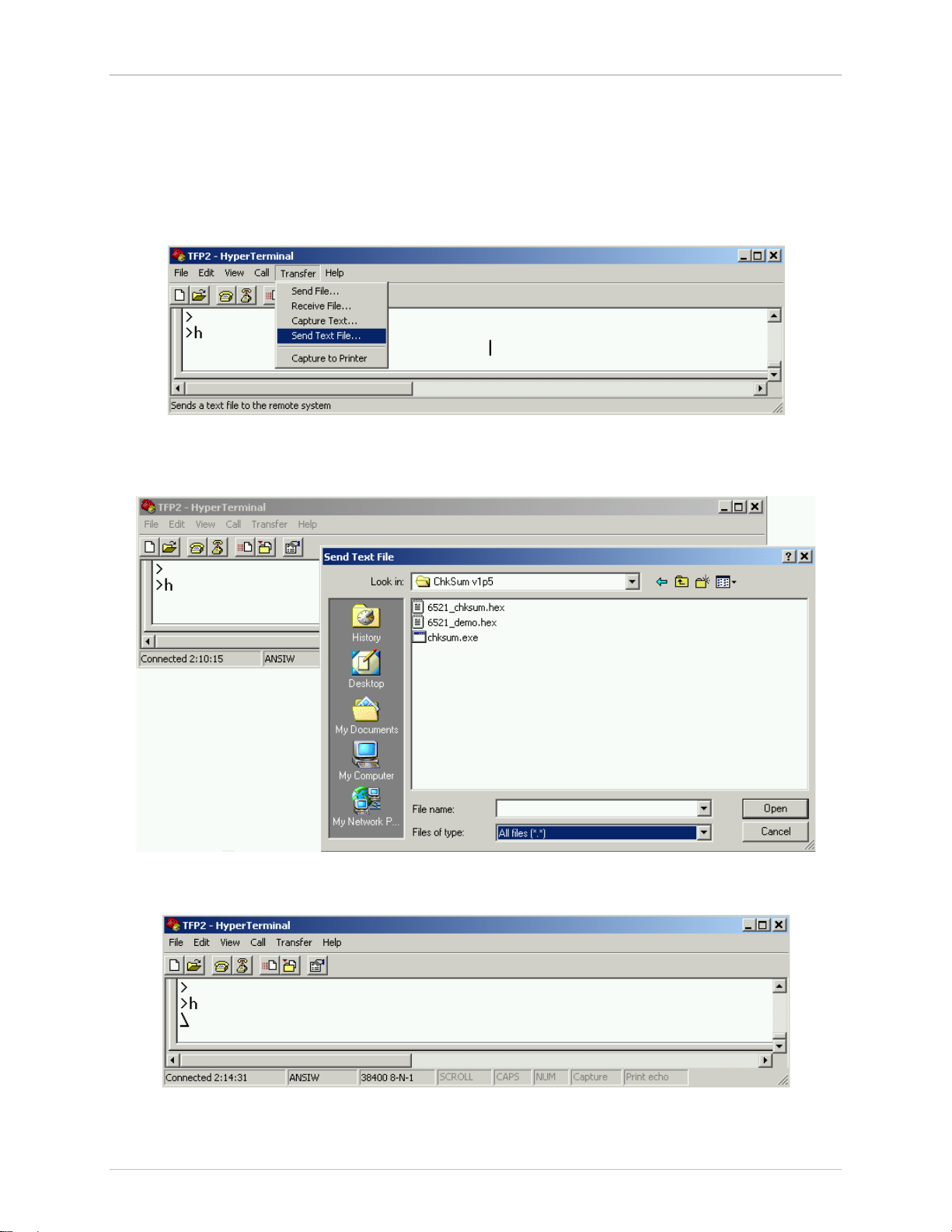
After typing “H” followed by the “Enter” key, the cursor m ov es to the following line. Next, click on the
“Transfer” button and scroll down to “Send Text File” to select t he desired f ile to be downloaded.
Figure 2-5: TFP2 Intel Hex File Download to Internal EEPROM Command
Enable the “All files (*.*)” for file type and select your desired t ar get Intel Hex code file from the
appropriate sub-directory.
Figure 2-6: TFP2 Select Target Intel Hex Fil e
Upon clicking on “O pen” a rot ating prompt is displayed indic ating the file download is in progress.
Figure 2-7: TF P 2 D ow nload in Progres s
When the file download completes, the number of bytes transferr ed is displayed. A running CRC is
calculated during the file download for each byte received for programming into the TFP2 internal
Revision 2.3 11 of 36
 Loading...