

TERIDIAN Semiconductor 73S8009C User Manual
73S8009C
Versatile Power Management
and Smar t C ard Interface IC
Simplifying System Integration™
DATA SH EET
DS_8009C_025 February 2010
When power is supplied by V
PC
or V
BAT
, the
73S8009C is contr olled by the ON_OFF pi n in the
DESCRIPTION
The Teridian 73S8009C is a versatile power
management and singl e smart ca r d interface ci r cuit
that is ideal ly su ited for smart card r eader pr oducts
that are battery and/or U SB bus-powered . In
addition to its EMV 4.1 and ISO-7816-3 compliant
smar t card-to-host int er face cir cuitry; it provides
control, co nversion, and regulati on of power for a
companion host processor circuit and power for the
smar t card. The 73S8009 C can operate from a
sin gle 2.7 V to 6.5 V source su ppl y, or a
combination of battery power (4.0 V to 6.5 V) and
USB power (4.4 V to 5.5 V).
The 73S80 09C suppor t s 5 V, 3 V, and 1.8 V smart
cards. The sm ar t card signals for R ST, CLK, IO,
and auxiliary signals AUX1 and AUX2 are
level-shifted t o the selected V
value. Although
CC
the host controller is required to handle the
detailed sign al timing for acti vation and deactivation und er norm al conditions, the 73S8009C
blocks any spurious signals on CLK, RST and IO
durin g po wer-up (as V
rises) and power-down.
CC
The 73S8009C co ntains two handshaking signals
for the cont r ol ler: OFF indicates that a card is
present, and RDY i ndicates that V
is at an
CC
acceptabl e value. The 73S8009C will per form
emergency deacti vation up on card removal,
voltage faults, or over-cu r r ent eve nts
The power management circuitry of the 73S8009C
allows operation from a wide range of voltages
from multiple sources. V
is converted by using
PC
an inductive, step-up power converter to the
intermediate volt age, V
. VP is used by linear
P
voltage regulators and switches to create t he
manner of a “push-on/push-off” button action. The
OFF_REQ and OFF_A C K signals provide
han dshaki ng and contr ol of the power “off”
functi on by the control l er . A SPST momentary
switch to ground connected to ON_OFF is all that
is required for power cont r ol. Alternatively, the
“off” state can be initi ated from the host co ntroller
thr ough OFF_ACK. When the 73S8009C is “off,”
the current is less than 1 µA.
When power is supplied via the V
pin, the
BUS
73S8009C is unconditionally in the “power-on”
state regardless of the action of th e ON/OFF
switch or OFF_ACK signal. Power supply current
operat ing from the V
power when VCC is off is
BUS
less than 500 µA to conform to USB “SUSPEND”
requirements.
APPLICATIONS
• Handheld PINpad smart card readers for
e-commerce, secure l ogin , e-health, Gov’t ID
and l oyalty
• Point of Sales & Transacti on Terminal s
• Gener al Pur pose Smart Card Read er s
ADVANTAGES
• Ideally suited to USB bus-powered
applications
Ideal for combo bus-powered and/or
self-powered syst ems
Automatic battery switchover in bus
powered systems
• Very low-power mode (sub-µA) with
push-button ON/OFF switch input with
de-bounce
voltages VDD and as required, VCC. VDD is use d by
the 73S8009C and i s also made available for th e
compani on contr oller circuit or oth er external
circuits. The V
BAT
and V
pins provide inputs
BUS
from alternate po wer sour ces as required. An
internal switch in the 73S8009C acts as a
single-pole, double-th r ow switch that selects either
or V
V
BAT
voltage on V
When voltage i s app lied to V
as the source for power.
V
BUS
to be connected to VPC. When the
BUS
is zer o, V
BUS
is connected to VPC.
BAT
, the switch selects
BUS
• Provid es 3. 3 V / 40 mA power to external
circuitry (host processo r or peripheral circuits)
• The inductor-based DC-DC converter pr ovides
higher current and efficiency than usual
charge-pump capacitor-based con verters:
Ideal for batt ery-powered applications
Rev. 1.5 © 20 10 Teridian Semi conductor Corp or ation 1

73S 8009C Data Sheet DS_8009C_025
FEATURES
• Smart card Interface:
• Complies with ISO-7816-3 and EMV 4. 1
and derivative standards
• A DC-DC Converter provides 1.8 V/3 V/5 V
to the card from a wid e r ange of external
power supply inputs
• Provid es up to 65 mA to the ca r d
• ISO-7816-3 Car d emer gency deactivation
sequencer
• 2 voltage supervisors detect voltage drops
on the V
(card) and VDD (digi tal) p ower
CC
supplies
• Card over-current detection 150 mA max.
• 2 card detection inpu ts, 1 for either user
polarity
• Auxiliary I/O lines for synchronous and
ISO-7816-12 USB card support
• Card CLK clock frequency up to 20 MHz
• 6 kV ES D and short ci r cuit protection on
the card interfac e
• System Controller Interface:
• 5 Signal im ages of the card sign al s
(RSTIN, CLKIN, I/OUC, AUX1UC and
AUX2UC)
• 2 Inputs activate and se l ect the card
voltage (CMDVCC% and CMDVCC#)
• 2 Outputs, interrupt to the system controller
(OFF and RDY), to inform the system
controller of the card presence / faults and
status of t he inter face
• 1 Chip Select i nput
• 2 Handshaking signals for proper shutdown
sequencing of all output supply voltages
(OFF_REQ, OFF_ACK)
• ON/OFF Mai n Sy ste m Sw i tch:
• Input for an SPST momentary switch to
ground
• DC-DC Converter:
• Step-up converter
• Generates an intermediar y voltage V
• Requires a single 10 µH Inductor
• System Power Sup ply requirements:
• When u sing VBUS: St andard US B +5
input (range +4.4 V to 5.5 V)
• When u sing V
: 4.0 V to 6.5 V
BAT
• When u sing VPC: 2.7 V to 6.5 V
• Autom ated det ection of voltage presence -
Priority on VBUS over VBAT
• Power Supply Output:
• V
supply output avail able to power up
DD
external circuitry: 3.3 V ±0.3 V, 40 mA
• Indust r i al temp er ature range
• Small form at QFN package
• RoHS compliant (6/6) lead-free package
P
2 Rev. 1.5

SMART CARD I/O BUFFERS
AND SIGNAL LOGIC
SWITCH/LDO
REGULATOR
VOLTAGE
REFERENCE
CONTROL
LOGIC
RESET
BUFFER
CLOCK
BUFFER
R-C
OSC.
VCC FAULT
VPC FAULT
1.5MHz
VDD
VBUS
VCC
RST
CLK
PRES
PRES
I/O
AUX1
AUX2
CLKIN
I/OUC
AUX1UC
AUX2UC
RSTIN
RDY
GND
OFF
TEST2
bias currents
vref
GND
VBAT
VPC
LIN
VCC OK
VCC = 3
VCC = 5
POWER DOWN
ON/OFF
ON_OFF
S2 S1
OFF_REQ
OFF_ACK
VP
CS
TEST1
3010
12
29
25
23
15
26
27
19
18
16
14
13
22
21
20
17
28
3
2
1
7
6
9
11
8
32
5
4
24
CMDVCC5
CMDVCC3
73S 8009C Data Sheet DS_8009C_025
FUNCTIONAL DIAGRAM
Pin numbers reference the QFN32 package.
Figure 1: 73S8009C Block Diagram
Rev. 1.5 3

73S 8009C Data Sheet DS_8009C_025
Table of Contents
1 Pinout ............................................................................................................................................. 6
2 Electrical Specifications .............................................................................................................. 10
2.1 Ab solute Maximum Rati ngs ................................................................................................... 10
2.2 Recommended Oper ating Conditions .................................................................................... 11
2.3 Smart Card Int er face Requ i r emen ts ...................................................................................... 11
2.4 Digital Signals Characteristics ............................................................................................... 14
2.5 DC Characteristics ................................................................................................................ 15
2.6 Volt age / Tem perature Fault Detection Circuit s ...................................................................... 15
2.7 Therm al Characteri stics ........................................................................................................ 15
3 Applications Information ............................................................................................................. 16
3.1 Example 73S8009C Schematics ........................................................................................... 16
3.2 Power Supply and Converter ................................................................................................. 18
3.3 Interface Function - ON/OFF Modes ...................................................................................... 18
3.4 System Controller Interface ................................................................................................... 20
3.5 Card Power Suppl y and V ol tage Supervision......................................................................... 20
3.6 Activation and D e-activation Sequence ................................................................................. 21
3.7 OFF and F ault D etection ....................................................................................................... 22
3.8 Chip Selection ....................................................................................................................... 23
3.9 I/O Circuitry and Timing......................................................................................................... 24
4 Equivalent Circuits ...................................................................................................................... 26
5 Mechanical Drawing .................................................................................................................... 30
6 Ordering Information ................................................................................................................... 31
7 Related Documentation ............................................................................................................... 31
8 Contact Information ..................................................................................................................... 31
4 Rev. 1.5

DS_8009C_025 73S8009C Data Sheet
Figures
Figure 1: 73S8009C Block Diagram ......................................................................................................... 3
Figure 2: 73S8009C 32-Pin QFN Pinout
Figure 3: Typical 73S8009C Application Schematic
Figure 4: 73S8009C Logical Block Diagram
Figure 5: Activation Sequence
Figure 6: D eactivation Sequence
Figure 7: OFF Activity
Figure 8: CS Timing Definit ion s
Figure 9: I/O and I/OUC State Diagram
Figure 10: I/O – I/OUC Delays - Timing Diagram
Figure 11: On_Off Pin
Figure 12: Open Drai n typ e – OFF and RDY
Figure 13: Power Input/Output Circuit, VDD, LIN, VPC, VCC, VP
Figure 14: Smart Card CLK Driver Circuit
Figure 15: Smart Card RS T Driver Circuit
Figure 16: Smart C ar d IO , AUX1, and AUX2 Interface Circuit
Figure 17: Smart Card I/OUC, AUX1UC and AUX2UC Interface Circuit
Figure 18: General Input Circuit
Figur e 19: OF F _REQ Inte r f a ce Circu i t
Figur e 20: 32-Pin QF N Package Dimensions
Tables
Table 1: 73S8009C Pin Definitions .......................................................................................................... 7
Table 2: Absolu te Maximum Device R atings
Table 3: Recommended Operating Conditions
Table 4: DC S mart Card Inter face Requirements
Table 5: Digital Signals Characteristics
Table 6: DC Characteristics
Table 7: Voltage / Temperature Fault D etection Circuits ......................................................................... 15
Table 8: Thermal Char acte r i stics
Table 9: Order Num bers and Packaging Marks
.................................................................................................. 6
............................................................................... 17
........................................................................................... 19
............................................................................................................... 21
........................................................................................................... 22
............................................................................................................................ 22
.............................................................................................................. 23
.................................................................................................. 24
.................................................................................... 25
............................................................................................................................ 26
.......................................................................................... 26
........................................................... 26
.............................................................................................. 27
.............................................................................................. 27
................................................................. 28
.................................................. 28
............................................................................................................. 29
................................................................................................... 29
......................................................................................... 30
.......................................................................................... 10
....................................................................................... 11
................................................................................... 11
.................................................................................................. 14
................................................................................................................... 15
........................................................................................................... 15
...................................................................................... 31
Rev. 1.5 5
73S 8009C Data Sheet DS_8009C_025
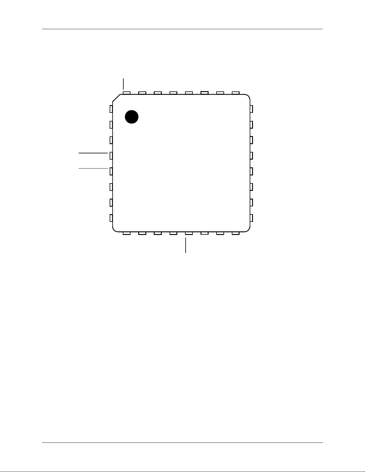
1 Pinout
The 73S8009C is supplied as a 32-pin QFN pa ckage.
LIN
VPC
VBAT
27
26
25
ON_OFF
24
I/OUC
GND
VDD
TEST2
GND
OFF
31
32
1
30
29
28
AUX1UC
AUX2UC
CMDVCC5
CMDVCC3
RSTIN
CLKIN
RDY
2
3
4
5
6
7
8
9
OFF_ACK
Figure 2: 73S8009C 32-Pin QFN Pinout
TERIDIAN
73S8009C
10
11
12
13
CS
TEST1
OFF_REQ
PRES
14
PRES
15
16
VP
CLK
23
22
21
20
19
18
17
VBUS
I/O
AUX1
AUX2
VCC
RST
GND
6 Rev. 1.5
DS_8009C_025 73S8009C Data Sheet
the pass through signal on RSTIN. Internal control logic
Miscellaneous Inputs and Outputs
–
–
–
–
Power Supply and Ground
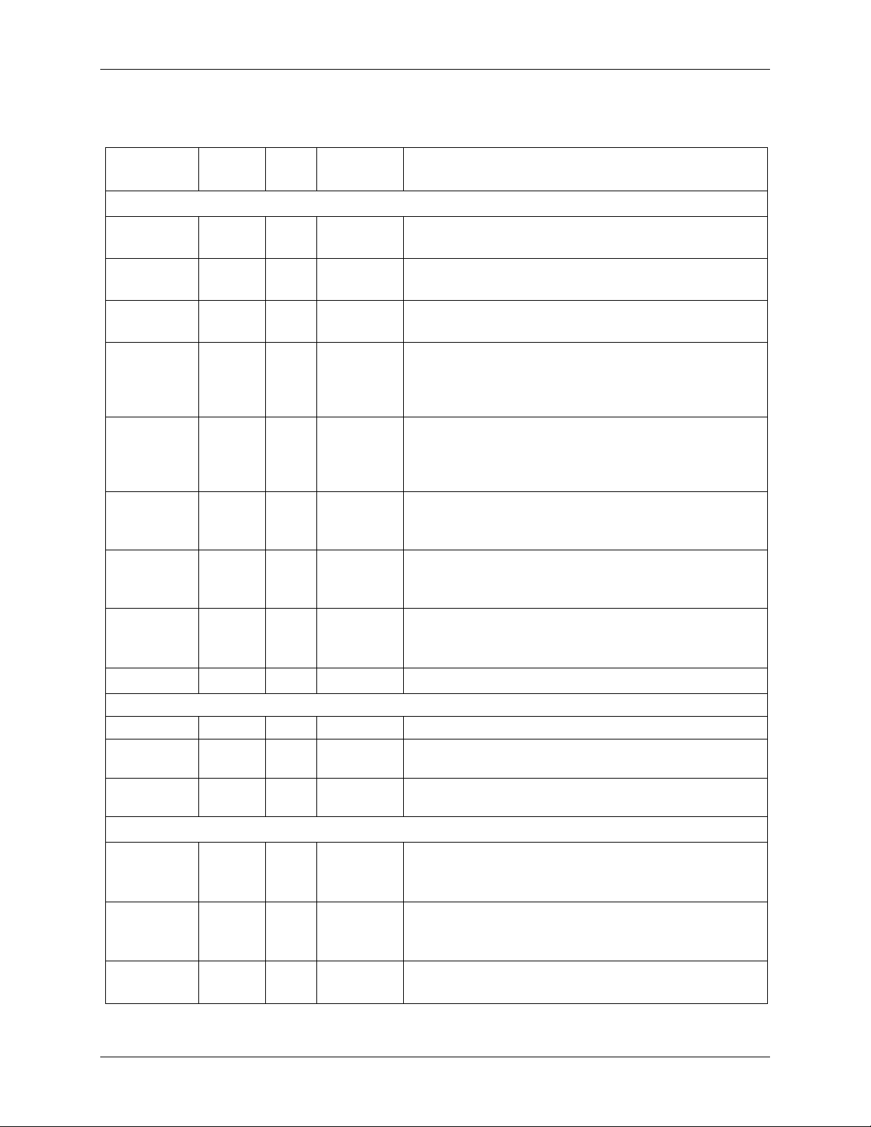
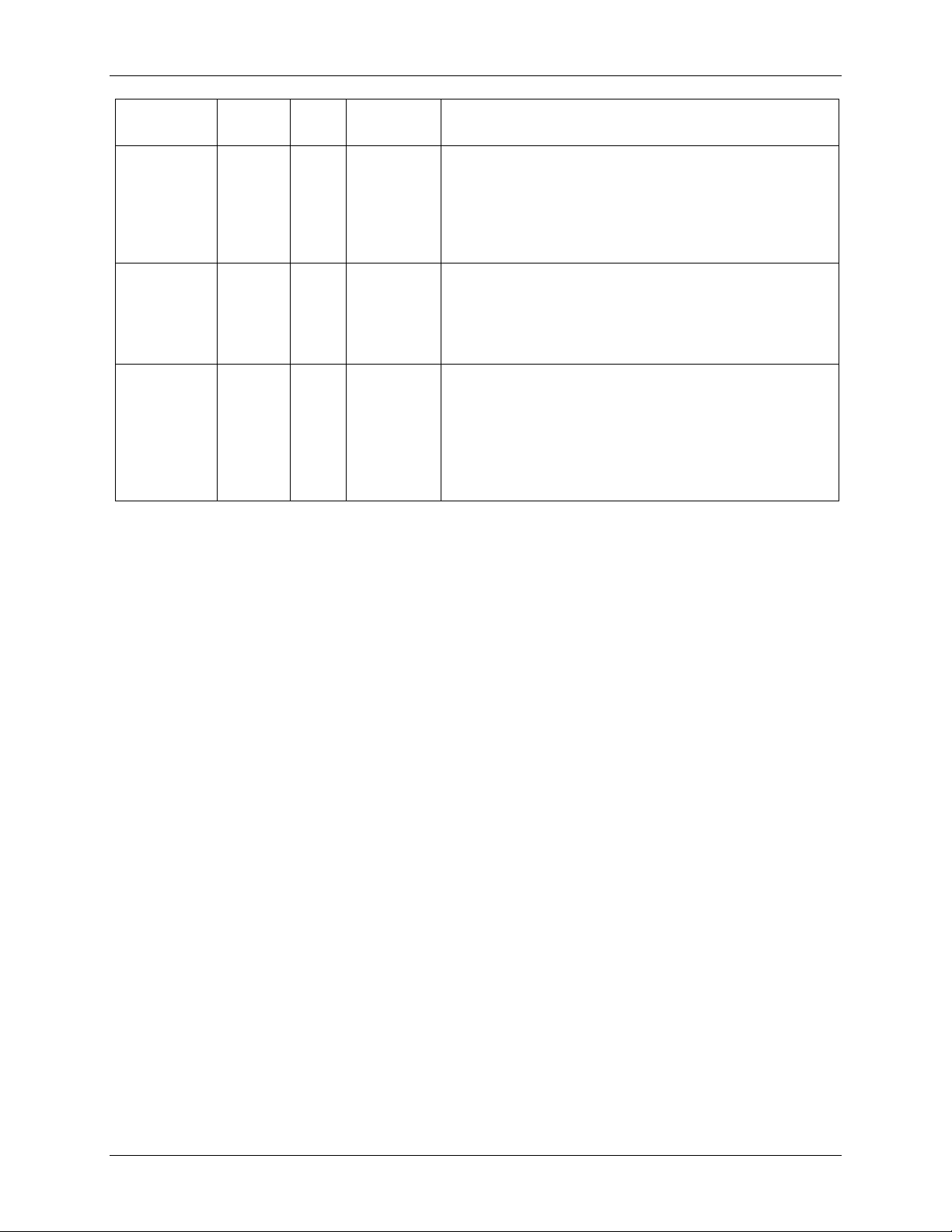
Table 1 describes the pin functions for the device.
Table 1: 73S8009C Pin Definitions
Pin
Name
Pin
(QFN32)
Type
Equivalent
Circuit
Description
Card Interface
I/O 22 IO Figure 16 C ar d I/O: Data signal to/from car d. Includes a pull -up
resistor to V
CC.
AUX1 21 IO Figure 16 AUX1: Auxiliary data signal to/from card. Includes a
pull-up resistor to V
CC.
AUX2 20 IO Figure 16 AUX2: Auxiliary data signal to/from card. Includes a
pull-up resistor to V
CC.
RST 18 O Figure 15 C ar d reset: pr ovides reset (RST) signal to card . RST is
will hold RST low when card is not act ivated or VCC is
too low.
CLK 16 O Figure 14 Card clock: pr ovides cl ock signal ( C LK) to card. CL K is
the pass through of th e signal on pin CLKIN. Internal
control logic will hold CLK low when card is not
activated or VCC is too low.
PRES 14 I Figure 18 Card Presen ce switch: active high i ndicates card is
present. Should be tied to GND when not used, but it
Includes a high-impeda nce pull-down current source.
PRES 13 I Figure 18 Card Presen ce switch: active low indicates ca r d is
present. Should be tie d to V
when not used, but it
DD
Includes a high-impeda nce pull-up cu r r ent so urce.
VCC 19 PSO Figure 13 Card power supply – log ically controlled by sequence r ,
output of LDO regulator. Requires an external 0.47 µF
low ESR filter capacitor to GND.
GND 17 GND – Card ground.
CLKIN 7 I Figure 18 Clock sign al source for th e card clock.
TEST1 10
Factory test pin. This pin must be tied to GND in
typical applications .
TEST2 30
Factory test pin. This pin must be tied to GND in
typical applications .
VDD 29 PSO
Figure 13 System interface supply voltage and supp ly voltage for
compani on contr oller circuitry. Req uires a min imum of
two 0.1 µF capacitors to ground for proper decoupling.
VPC 26 PSI
Figure 13 Power supply sou r ce for main voltage converte r circuit.
A 10 µF a nd a 0. 1 µF ceramic capacitor must be
connected to this pin.
VBAT 25
Alternate power source input, typically from t wo ser ies
cells, V > 4 V.
Rev. 1.5 7
73S 8009C Data Sheet DS_8009C_025
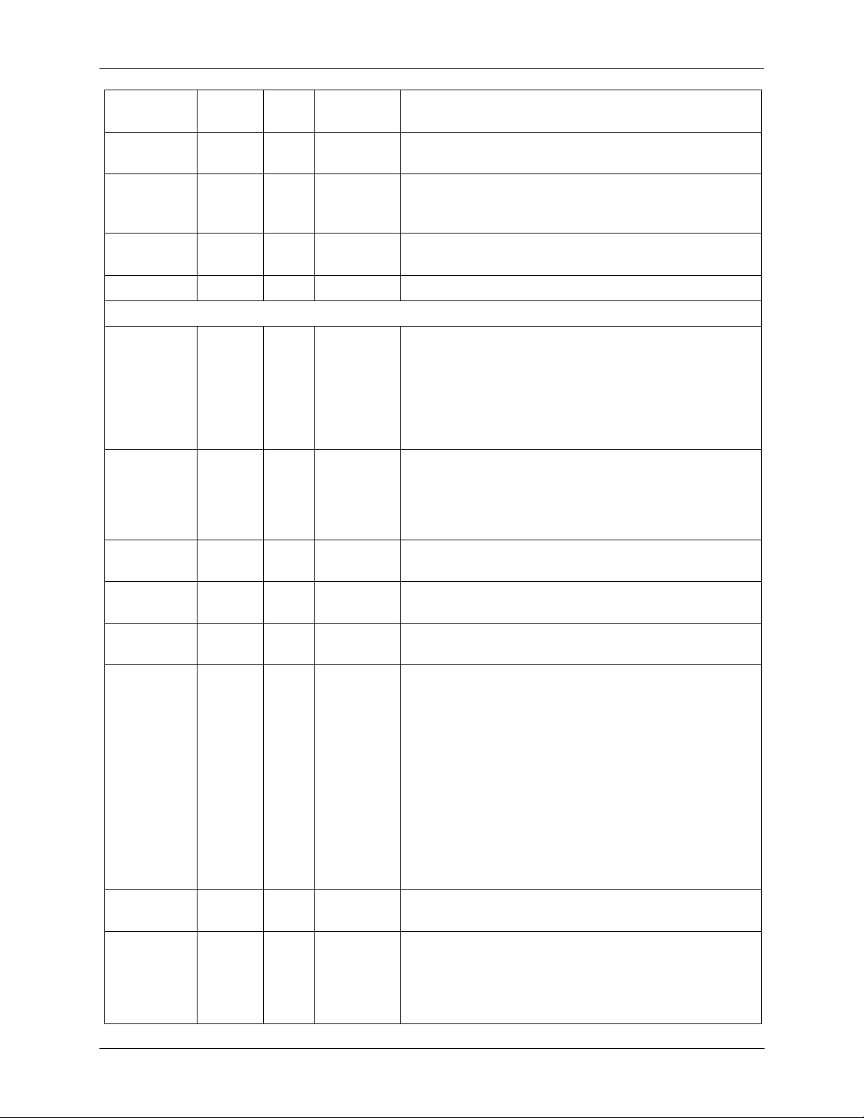
When CS = 1, the control and signal pins are configured
up is disabled in Power down
Pin
Name
VBUS 23
LIN 27 PSI
VP 15 PSO
GND 28,31
Pin
(QFN32)
Type
Equivalent
Circuit
A l ternate power source i nput from USB con nect or or
Figure 13
Figure 13 Intermediate output of main converter circuit. Requires
– Ground.
Microcontroller Interface
CS
OFF 32 O
12
I
Figure 18
Figure 12
I/OUC 1 IO Figure 17
AUX1UC 2 IO Figure 17
AUX2UC 3 IO Figure 17
CMDVCC%
CMDVCC#
4
5
I
I
Figure 18
Description
hub.
Connection to 10 µH indu ctor for internal step up
converter. Note: i nductor must be rated for 400 mA
maximum peak current.
an external 4.7 µF low ESR filter capacitor to GND.
normally. When CS is set l ow, CMDVCC%, RSTIN, and
CMDVCC# are l atch ed. I/OUC, AUX1 UC, and
AUX2UC are set to high-impedan ce pull-up mode and
do n ot pass data to or from the smart card . Signal s
RDY and OFF are disab led to pr event a low output and
the inter nal pull-up resistors are disconnected.
Interrupt si gnal to the proce ssor. Active Low - Multifunction indicating fault conditions and card presen ce.
Open drain output configuration – It in cludes an inter nal
20 kΩ pull-up to V
DD.
Pull-
state and C S = 0 modes.
System controll er data I/O to/ from the card. Includes a
pull-up resistor to V
DD.
System controll er auxiliary data I/ O to/ from the card.
Includes a pull-u p r esistor to V
DD.
System controll er auxiliary data I/ O to/ from the card.
Includes a pull-u p r esistor to V
DD.
Log i c low on on e or both of these pins will cause the
LDO to ramp the Vcc supply to the smart card and
smar t card interface to the value descr ibed i n the
following table.
CMDVCC% CMDVCC# Vcc Output V ol tage
0 0 1.8 V
0 1 5.0 V
1 0 3.0 V
1 1 LDO Of f
Note: See the description of the Card Power Supply for
more detail on the operation of CMDVCC% and
CMDVCC#.
RSTIN 6 I
RDY 8
Figure 18 Reset Input: This signal is the rese t command t o the
Figure 12 Signal to co ntroller indi cating the 73S8009C is ready
8 Rev. 1.5
card.
because V
is above the required value after
CC
CMDVCC% and/or CMDVCC# is asserted low. A 20 kΩ
pull-up resistor to V
is provided internally. Pull-up is
DD
disabled in Power down state and CS=0 modes.
DS_8009C_025 73S8009C Data Sheet
bounce period will turn 73S8009C circuit “on.”
If 73S8009C is “on,” closing switch will turn 73S8009C
turn the 73S8009C off. If ON_OFF switch is closed (to
Pin
Name
Pin
(QFN32)
ON_OFF 24 I
OFF_REQ 11 O
OFF_ACK 9 I
Type
Equivalent
Circuit
Figure 11
Power co ntrol pin . Connected to normally open SPST
Description
switch to ground. Closing switch for durat ion great er
than de -
to “off” state after the d e-bounce peri od and
OFF_REQ/OFF_ACK handshake.
Figure 19
Digi tal output. Requ est to the host system control l er to
ground) for de-bounce duration and circuit is “on,”
OFF_REQ will go high (Request to turn OFF).
Connected to O FF_ACK via 100 kΩ internal resist or .
Figure 18 Sett ing OFF_ACK hi gh will power “off” all analog
functions and disconnect the 73S8009C from V
V
. The pin has an internal 100 kΩ resistor
PC
connecti on to OFF_REQ so that wh en not co nnected or
no h ost int er action is required, th e Acknowledge wil l be
true and the circuit will turn “off” immediately with
OFF_REQ.
BAT
or
Rev. 1.5 9
73S 8009C Data Sheet DS_8009C_025
2 Electrical Specifications
This section provides the following:
Absolute maximum ratings
Recommended op erating conditi o ns
Smart card inter face requirements
Digital signals characteristics
Volt age / temperature fault d etection cir cuits
Therm al characteristics
2.1 A bsolute Maximum Ratings
Table 2 l i sts the maximum operating condit ions for the 73S8009C. Permanent device damage may occur
if absol ute maximum rati ngs are exceeded. Exposure to the extrem es of the absolut e m aximum r ating for
extended periods may affect devi ce reliabili ty. The smar t card interface pins are protected against short
circuits to V
Parameter Rating
Sup ply Voltage V
Sup ply Voltage V
Sup ply Voltage VPC -0.5 to 6. 6 VDC
VDD -0.5 to 4. 0 VDC
Input Voltage for Di gital Inputs -0.3 to (VDD +0.5) VDC
Stor age Temperatu r e -60 to 150° C
Pin Voltag e ( except card interface) -0.3 to (VDD + 0.5) VDC
Pin Voltag e ( card interface) -0.3 to (VCC + 0.3) VDC
Pin Voltage, LIN pin 0.3 to 6.5 VDC
ESD Tolerance – Card interface pins +/- 6 kV
ESD Toleran ce – Other pins +/- 2 kV
Pin Current, except LIN
Pin Cur r e nt, LIN + 500 mA in, -200 mA out
Note: ESD testin g on smart card pi ns is HBM cond i tion, 3 pulses, each polarity referenced to gr ound.
Note: Smart C ar d pi ns are protected against shorts between any combin ations of Sm ar t Card pi ns.
, grou nd, and each other.
CC
Table 2: Absolute Maximum Device Ratings
-0.5 to 6. 6 VDC
BUS
-0.5 to 6. 6 VDC
BAT
± 200 m A
10 Rev. 1.5
 Loading...