

Teridian 78Q2120C09 User Manual
78Q2120C09
10/100BASE-TX Transceiver
UM 78Q2120C09 v1-2
DESCRIPTION
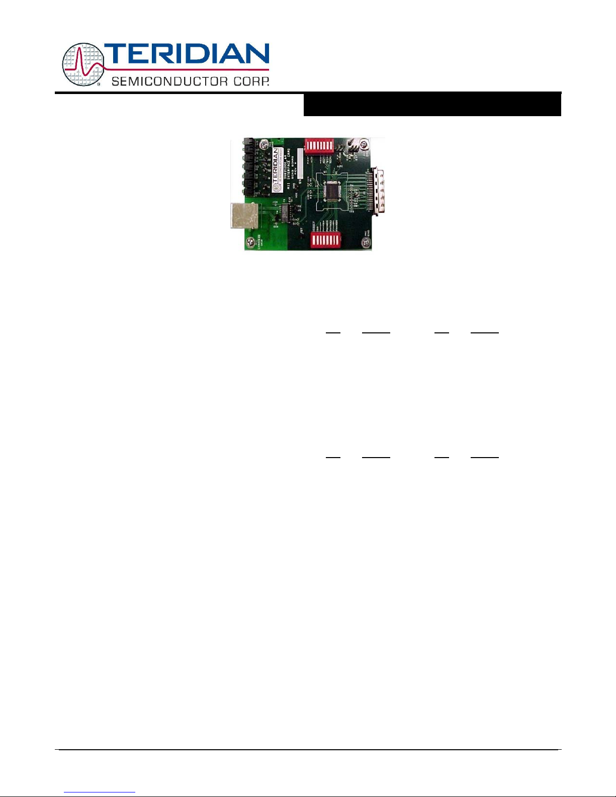
The 78Q2120C09-DB is a design example for a
10/100BASE-TX Mbit/second Fast Ethernet MII
Interface adaptor. The 78Q2120C09 transceiver
provides the network physical interface and MII
(Medium Independent Interface) interface.
Teridian Semiconductor’s 78Q2120C09 is an autosensing, auto-switching 10/100BASE-TX Fast
Ethernet transceiver with full duplex operation
capability. The device interfaces directly to the
IEEE-802.3u MII port. Full-featured MII
management functions are included along with an
extended register set. A five bit configurable PHY
address is provided for multiple PHY architectures.
The 78Q2120C09 interfaces to CAT5 UTP cable via
a 1:1 transformer.
The transceiver’s transmitter includes on-chip the
pulse shaper and low power line driver. The
receiver incorporates a sophisticated combination of
real-time adaptive equalization, an adaptive DC
offset adjustment circuit and baseline wander
correction. Smart squelch circuitry further improves
the receiver’s noise rejection. Full featured autonegotiation or parallel detect modes are supported.
Using 0.18µm CMOS technology, the 78Q2120C09
operates at +3.3V. Intelligent power management
and power down modes minimize power
consumption. The demo board requires operation
with a +3.3V power supply.
Design Kit contains:
√ 78Q2120C09 MII Demo Board
√ Demo Board Parts List
√ P.C.B. Gerber Files
√ Demo Board schematic
√ 78Q2120C09 Data Sheet
MII Evaluation Board Design Kit
User Manual
April 2007
100Base-TX Interface
RJ45 Pin Assignment
Pin Signal Pin Signal
1 TX+ 5 N/C
2 TX- 6 RX3 RX+ 7 N/C
4 N/C 8 N/C
MII: Medium Independent Interface
Pin Assignment:
(40 Pin Male Subminiature D, 0.050)
Pin
Signal Pin Signal
1 +3.3V 21 +3.3V
2 MDIO 22 COMMON
3 MDC 23 COMMON
4 RXD3 24 COMMON
5 RXD2 25 COMMON
6 RXD1 26 COMMON
7 RXD0 27 COMMON
8 RXDV 28 COMMON
9 RXCLK 29 COMMON
10 RXER 30 COMMON
11 TXER 31 COMMON
12 TXCLK 32 COMMON
13 TXEN 33 COMMON
14 TXD0 34 COMMON
15 TXD1 35 COMMON
16 TXD2 36 COMMON
17 TXD3 37 COMMON
18 COL 38 COMMON
19 CRS 39 COMMON
20 +3.3V 40 +3.3V
© 2007 Teridian Semiconductor Corporation, Proprietary and Confidential - 1 - Rev_1.2

78Q2120C09
10/100BASE-TX Transceiver
UM 78Q2120C09 v1-2
MII Evaluation Board Design Kit
User Manual
April 2007
MII ADAPTOR WITH 78Q2120C09
Switch Positions
The OFF switch position sets a logic level = “1” and conversely, the ON position sets a logic level = “0”.
Some DIP switch markings are different.
ON equals CLOSED.
OFF equals OPEN.
For normal operation switch SW2 should be set as follows:
ISO ON
ISODEF ON
TEST ON
PAD4:0 PHY Address = 0, the 78Q2120C09 responds to all accesses
PHY Address = non-zero, the 78Q2120C09 responds only to its unique address
For normal operation the following SW1 switches should be set as follows:
N/U OFF (not used)
PCSBP ON
PWRDN ON
Switch SW1 positions ANEGA and TECH0:2 set the line interface technology capabilities.
Refer to the data sheet for a complete description.
For full Auto-Negotiation capabilities, set ANEGA and TECH0:2 to OFF.
Use With the Netcom Smart-Bits
The Netcom expects to be the master and defaults to 100BASE-TX Half-Duplex operation. To allow Fast-Ether
Windows to reconfigure the 78Q2120C09’s control register MR0 bits, set ANEGA and TECH0:2 all to OFF. If the
78Q2120C09’s technology pins are set to anything else, the 78Q2120C09 will disable some modes and prevent
the Netcom from reconfiguring the 78Q2120C09 and data errors may be observed.
After initialization the 78Q2120C09 defaults to 100BASE-TX Full-Duplex operation. When connected to another
fully capable transceiver, the transceivers will be in full-duplex mode. The default configuration of the Netcom is
100BASE-TX Half-Duplex operation. If data transfers were to commence, the Netcom would display Collision
errors (because it does not automatically read the transceivers and reconfigure).
If a transceiver is used which defaults to 100BASE-TX Half-Duplex operation, the 78Q2120C09 will adjust itself
for half-duplex operation (assuming the 78Q2120C09 is setup for the proper technologies).
To establish proper operation between the 78Q2120C09 and the Netcom, click on the “Options” button followed
by selecting “Full Duplex MII”. Repeat selecting “Full Duplex MII” twice to ensure that everything is configured
identically.
The 78Q2120C09 can be configured for half-duplex operation (ANEGA = ON and TECH0:2 = ON, OFF, ON) to
minimize incompatibilities with other transceivers and the Netcom.
© 2007 Teridian Semiconductor Corporation, Proprietary and Confidential - 2 - Rev_1.2
78Q2120C09
MII Evaluation Board Design Kit
User Manual
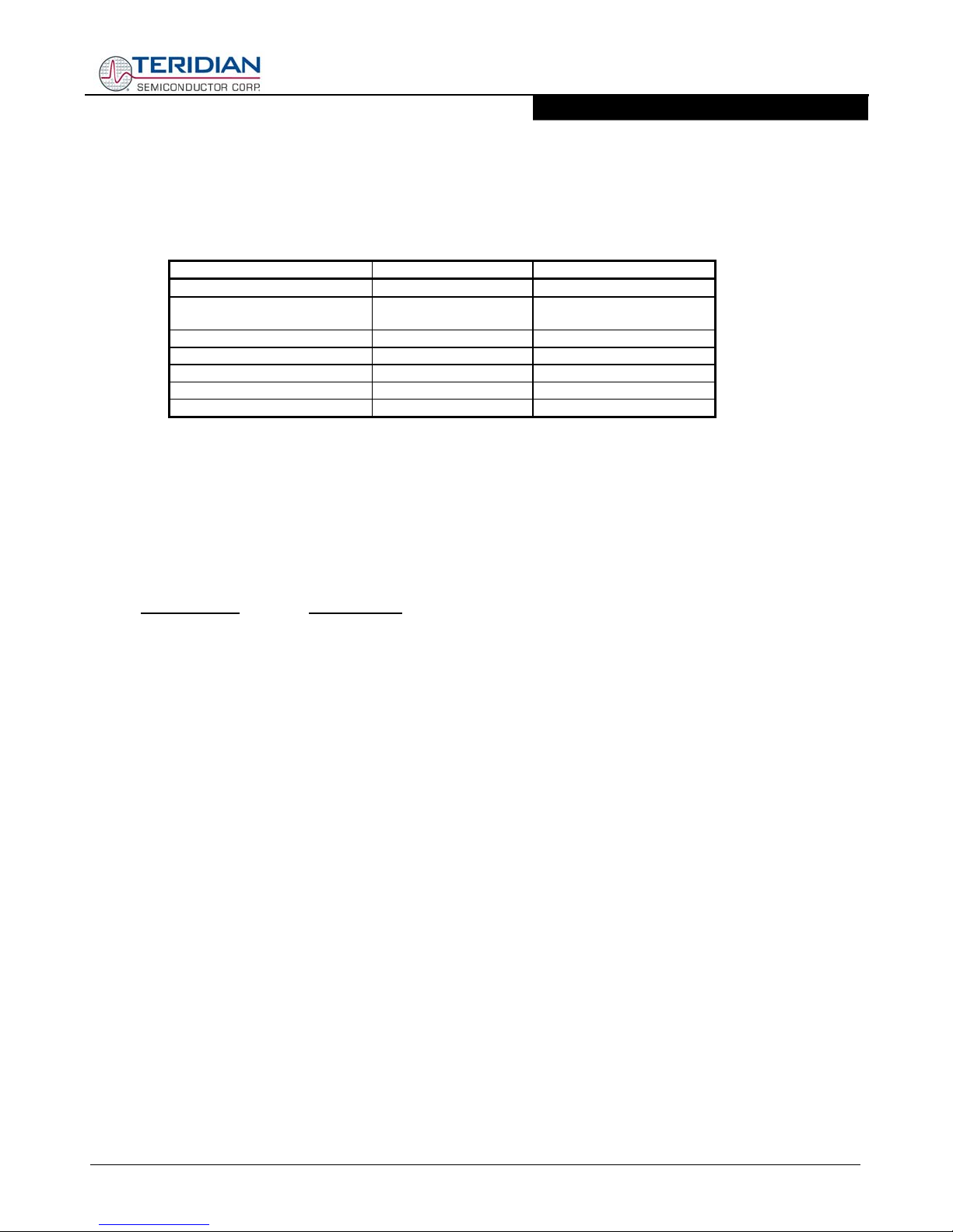
10/100Mbps Transformer Selection
The line interface for the 78Q2120C09 requires a pair of 1:1 isolation transformers. Integrated common-mode
chokes are recommended for satisfying FCC radiated EMI requirements. Additional filtering is not required with
the 78Q2120C09 due to internal waveform shaping circuitry. The line transformer characteristics are outlined
below:
Name Value Condition
Turns Ratio 1 CT : 1 CT
Open-Circuit Inductance 350 µH (min)
See Note 1.
Leakage Inductance 0.40 µH (max) @ 1 Mhz (min)
Inter-Winding Capacitance 25 pF (max)
D.C. Resistance 0.9 ohm (max)
Insertion Loss 1.1 dB (typ) 0 - 100 Mhz
HIPOT 1500 Vrms
Note 1: The receive line transformer’s Open-Circuit Inductance can be as low as 100 µH for the 78Q2120C09.
The 78Q2120C09 incorporates baseline wander correction circuitry which allows the receiver to track the
incoming data signal when there is excessive transformer droop.
For Commercial Temperature (0°C ~ 70°C)
Teridian Semiconductor has performed line testing with the following transformers and found their performance
acceptable with the 78Q2120C09:
Manufacturer
Part Number
TDK TLA-6T103
Bel-Fuse S558-5999-46
Halo TG22-3506ND
Pulse PE-68515
Valor ST6118
YCL 20PMT04
The following transformers are low profile packages (0.100 in/2.5 mm or less).
TDK TLA-6T118
Halo TG110-S050
PCA EPF8023G
@ 10 mV, 10 KHz
fd
© 2007 Teridian Semiconductor Corporation, Proprietary and Confidential - 3 - Rev_1.2
78Q2120C09
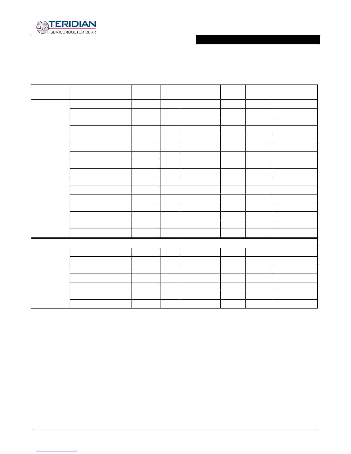
The following devices integrate the transformers, RJ45 connector, LEDs and termination resistors.
Commercial Temperature Connectors
Vendor Part number
Tab up
/down
LED
LED color
(L/R)
J0011D21 Down No N/A Yes No a
J0011D21NL Down No N/A Yes Yes a
J0011D21B Down Yes G/Y Yes No b
J0011D21BNL Down Yes G/Y Yes Yes b
J0011D21E Down Yes G/G Yes No b
J0011D21ENL Down Yes G/G Yes Yes b
J0011D01 Down No N/A Yes No a
Pulse
J0011D01NL Down No N/A Yes Yes a
J0011D01B Down Yes G/Y Yes No b
J0011D01BNL Down Yes G/Y Yes Yes b
J0012D21 Down No N/A Yes No a
J0012D21NL Down No N/A Yes Yes a
J1011F01P Up Yes G/Y Yes No A
J1011F01PNL Up Yes G/Y Yes Yes A
J1011F21P Up Yes G/Y Yes No A
J1011F21PNL Up Yes G/Y Yes Yes A
HFJ11-2450EURL Down No N/A No Yes e
HFJ11-2450EU-L11RL Down Yes G/G No Yes f
HFJ11-2450ERL Down No N/A Yes Yes c
Halo
HFJ11-2450E-L11RL Down Yes G/G Yes Yes d
HFJT1-S003E-L11RL Up Yes G/G Yes Yes B
HFJT1-S003-L11RL Up Yes G/G Yes Yes C
HFJT1-S003 Up No N/A Yes Yes D
MII Evaluation Board Design Kit
User Manual
Shielding Lead-free
fd
Compatible
Footprints *
© 2007 Teridian Semiconductor Corporation, Proprietary and Confidential - 4 - Rev_1.2

78Q2120C09
Commercial Temperature Connectors (continued)
Vendor Part number
Tab up
/down
LED
LED color
(L/R)
MIC24010-5101T-LF3 Down No N/A Yes Yes b
MIC24010-5104T-LF3 Down No N/A Yes Yes b
MIC24011-0101T Down Yes Y/G Yes No b
MIC24011-0101T-LF3 Down Yes Y/G Yes Yes b
MIC24011-0101W-LF3 Down Yes Y/G Yes Yes b
MIC24011-0104T Down Yes Y/G Yes No b
MIC24012-5101T-LF3 Down Yes G/G Yes Yes b
Wurth/Midcom
MIC24012-5204T-LF3 Down Yes G/G Yes Yes b
MIC24013-5104T Down Yes G/Y Yes No b
MIC24018-5101T-LF3 Down Yes R/G Yes Yes b
MIC24019-0101T Down Yes G/R Yes No b
MIC24111-0101T Up Yes Y/G Yes No A
MIC24111-0101T-LF3 Up Yes Y/G Yes Yes A
MIC24412-0128T-LF3 Up Yes G/G No Yes E
MIC24F11-0101T-LF3 Up Yes Y/G No Yes F
LJ0004 Down No N/A Yes Yes a
Falco
LJ0012 Down No N/A Yes No a
LJ1011 Down Yes G/Y Yes No d
SI-10021 Down No N/A Yes No a
SI-60002-F Down No N/A Yes Yes a
SI-40139 Down Yes G/G Yes No d
SI-60001-F Down Yes G/G Yes Yes d
SI-50170 Up Yes G/G Yes No A
BelFuse
SI-50170-F Up Yes G/G Yes Yes A
SI-50177 Up No N/A Yes No D
SI-50177-F Up No N/A Yes Yes D
SI-50193 Up No N/A No No G
SI-50193-F Up No N/A No Yes G
SI-50196 Up Yes G/G No No F
SI-50196-F Up Yes G/G No Yes F
MII Evaluation Board Design Kit
User Manual
Shielding Lead-free
Compatible
Footprints *
fd
TDK
TLA-6T704 Down No N/A Yes Yes a
TLA-6T707 Down No N/A Yes Yes a
© 2007 Teridian Semiconductor Corporation, Proprietary and Confidential - 5 - Rev_1.2

78Q2120C09
* Notes:
1. The letters stand for different footprint drawings
2. Lower case is for the tab-down version. Upper case is for tab-up version.
3. The compatible connectors are labeled with the same letter.
The above evaluations were performed using Netcom’s Smart-Bits Fast Ethernet Analyzer. The Teridian
Semiconductor 78Q2120C09 MII Adapter and Lancast Fast Ethernet Adapter were attached to the Netcom’s
Ports A & B respectively. Twisted pair Category 5 General Cable P/N 459360 was used to connect the two
transceivers. 100 Mbps performance was measured using cable lengths of both 12 inches and 115 meters. 10
Mbps performance was evaluated using 100 meters of Category 3 cable.
The Netcom was configured to use the Baseline Wander Packet file. Packet length was 1500 bytes.
All transformers listed above met or exceeded IEEE’s 802.3 Bit Error Rate requirements of 10
MII Evaluation Board Design Kit
User Manual
-8
.
fd
© 2007 Teridian Semiconductor Corporation, Proprietary and Confidential - 6 - Rev_1.2
 Loading...