

Teridian 73S1215F User Manual

Simplifying System In tegrationTM
73S1215F
Evaluation Board Lite User Guide
Augu st 17, 2009
Rev. 1.1
UG_1215F_045

73S1215F Evaluation Board Lite User Guid e UG_1215F_045
© 20 09 Teridi an Semiconductor C or porati on. All rights r eserved .
Teridian Semiconductor Corporation is a registered trademark of Teridian Semiconductor Corporation.
Simplifying System Integration is a trademark of Teri dian Semiconductor Corporation.
Microsoft, Windows and Vista are register ed trademar ks of Micr osoft Corporation.
Signum is a trademark of Si gnum Systems Corporation.
Keil i s a trademark of ARM® Ltd.
Linux is a registered trademark of L inus Torvalds.
Slackware is a r egistered trademark of Patrick V olkerding and Sl ackware Linux, Inc.
Fedora i s a registered t r ademar k of RedHat, I nc.
All oth er trademarks are th e prop er ty of their r espective owners.
Terid i an Semiconductor Corporation m akes no warranty for the use of its p r oduct s, other than expressly
contained in the Comp any’s warranty d etailed in the Terid ian S emiconductor Corporation st andar d Terms
and C onditions. The company assu mes no responsib i lity for any errors whi ch may appear in this
document, reserves th e r i ght to change device s or sp ecifications detailed herein at any time withou t
notice and does n ot make any commitm ent to upd ate the informati on contained herein. A ccord ingly, the
reader is cautioned to verify that t his document is current by comparing it to the latest version on
http://www.teridian.com or by checking with your sal es representati ve.
Terid i an Semiconductor Corp., 64 40 Oak Canyon, Suite 100, Ir vine, CA 92618
TEL (714) 508-8800, FAX (714) 508-8877, http://www.teridian.com
2 Rev. 1.1

UG_1215F_045 73S1215F Evaluation Board Lite User Guide
Table of Contents
1 Introduction ................................................................................................................................... 5
1.1 Evaluation Board LIte Package Contents .............................................................................. 6
1.2 Evaluation Board Lite Featu r es ............................................................................................. 6
1.3 Recommended Equ ipment and Test Tools ............................................................................ 6
2 Evaluation Board Lite Basic Setup ............................................................................................... 7
2.1 Connecti ng the Evaluati on Board Li te with an Emul ation Tool ............................................... 8
2.2 Load i ng U ser Code into the Evaluat ion B oar d Lite................................................................. 8
3 Using the USB CCID Application ................................................................................................ 10
3.1 Driver and Software Installation ........................................................................................... 10
3.1.1 Installation on Wind ows XP ....................................................................................... 10
3.1.2 Installation on a Lin ux System ................................................................................... 11
3.2 Fre que nt ly Asked Questions ............................................................................................... 11
4 73S1215F Evaluation Board Lite Hardware Description ............................................................ 13
4.1 Jumpers, Switch es and Test Points..................................................................................... 13
4.2 Schematic........................................................................................................................... 16
4.3 PCB Layouts....................................................................................................................... 17
4.4 Bill of Materials ................................................................................................................... 20
4.5 Schematic In formati on ........................................................................................................ 22
4.5.1 Reset Circuit.............................................................................................................. 22
4.5.2 Oscillators ................................................................................................................. 22
4.5.3 USB In terface ............................................................................................................ 23
4.5.4 Smart Card Interface ................................................................................................. 23
5 Ordering Information ................................................................................................................... 25
6 Related Documentation ............................................................................................................... 25
7 Contact Information ..................................................................................................................... 25
Revision H istory .................................................................................................................................. 26
Rev. 1.1 3

73S1215F Evaluation Board Lite User Guid e UG_1215F_045
Figures
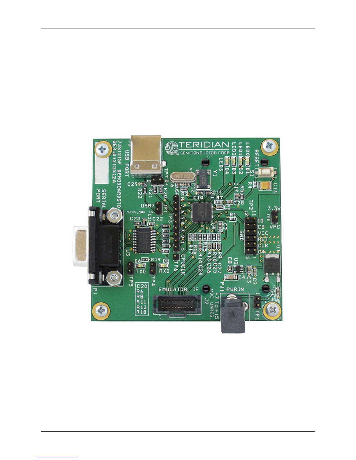
Figure 1: 73S1215F Evaluation Board Lite ............................................................................................... 5
Figure 2: 73S1215F Evaluation Board Lite Basic C onnections
Figure 3: Emulator Window Showing RESET and ERASE Buttons
Figure 4: Emulator Wind ow Showing Erased Flash Memory and File Load Menu
Figure 5: 73S1215F Evaluation Board Lite Jumper, S witch and Test Point L ocation
Figure 6: 73S1215F Evaluation Board Lite Elect r i cal Schematic
Figure 7: 73S1215F Evaluation Board Lite Top Vi ew (Silkscreen)
Figure 8: 73S1215F Evaluation Board Lite Bottom View (Si l kscreen)
Figure 9: 73S1215F Evaluation Board Lite Top Si gnal Layer
Figure 10: 73S1215F Evaluation Board Lite Mid dle Layer 1 – Ground Plane
Figure 11: 73S1215F Evaluation Board Lite Middle La yer 2 – Supply Plane
Figure 12: 73S1215F Evaluation Board Lite Bot tom Sig nal Layer
Figure 13: Extern al Components for RESET
Figure 14: Oscillator Circu it
Figure 15: USB C onnect ions
Figure 16: Smart C ar d Con nect i ons
Tables
Table 1: Flash Programming Interface Signals ......................................................................................... 8
Table 2: Evaluation Board Lite Jum per, Swit ch and Test Poi nt Description
Table 3: 73S1215F Evaluat ion B oar d Lite Bill of Materials
................................................................. 7
........................................................... 9
..................................... 9
............................... 15
............................................................. 16
.......................................................... 17
..................................................... 17
.................................................................. 18
.......................................... 18
........................................... 19
........................................................... 19
.......................................................................................... 22
.................................................................................................................... 22
.................................................................................................................. 23
....................................................................................................... 24
............................................. 13
...................................................................... 20
4 Rev. 1.1
UG_1215F_045 73S 1215F Evaluation Board Lite User Guide
1 Introduction
The Teridian Semiconductor Corporation (TSC) 73S1215F Evaluation Board Lite is used to demonstrate
the capabilit i es of the 73S1215F Smart Card Controller devic es. It has b een designed to operat e either
as a st andal one or a development platform.
The 73S1215F Evaluation Board Lite ca n be programmed to run any of the Terid ian turnkey appl i cations
or a user -developed custom appl ication. Teridian provides its USB CCID application preloaded on the
board and an EMV testing application on the CD.
Appli cations can be downloaded through the In-Circuit-Emulator (ICE) or through the TSC Flash
Programmer Mod el TFP2. As a developm ent tool, th e Evaluation Board Lite has been designed to
operat e in conjunct i on with an ICE t o develop and debug 73S1215F based em bedded appli cations.
Rev. 1.1 5
Figure 1: 73S1215F Evaluation Board Lite

73S1215F Evaluation Board Lite User Guid e UG_1215F_045
1.1 Evaluation Board LIte Packa ge Contents
The 73S1215F Evaluation Board Lite package cont ai ns th e fol l owing:
• 73S1215F Evaluation Board Lite: 4-layer, square PWB as shown in Figure 1, containing the
73S1215F with the preloaded turnkey program USB CCID.
• 12 VDC/1,000 mA universal wall transformer with 2.1 mm plug ID (CUI Inc. – EPAS-101W-12).
• USB cable , A/ B, male, 2 meters ( Digi-Key AE1379-ND).
• CD containing d ocumentation (dat a sheet, board schem atic, BOM and l ayout), evaluation code and
utilities.
1.2 Evaluation Board Lite Features
The 73S1215F Evaluation Board Lite (see Figure 1) includes the following features:
• USB 2.0 full speed interface
• RS-232 interface
• Single smart ca r d inter face
• ICE /Programmer interface
• Real Time Clock (RTC) capability
• 4 LEDs
1.3 Recommended Equipment and Test Tools
The following equipment and tools ( not provided) are recommended for use with the 73S1215F
Evaluation Board Lite package:
• For functional evaluation: PC with Microsoft® Windows® XP or Vista® or a Linux® workstation,
equipped with an RS232 (CO M ) port and or a USB port.
• For software devel opm ent (MPU code)
Signum™ ICE (In C ircuit Emulator): ADM-51 . R efer to
http://signum.temp.veriohosting.com/Signum.htm.
Keil™ 8051 C Compil er Kit: CA51. Refer to http://www.keil.com/c51/ca51kit.htm and
http://www.keil.com/product/sales.htm
.
6 Rev. 1.1
UG_1215F_045 73S 1215F Evaluation Board Lite User Guide
2 Evaluation Board Lite Basic Setup
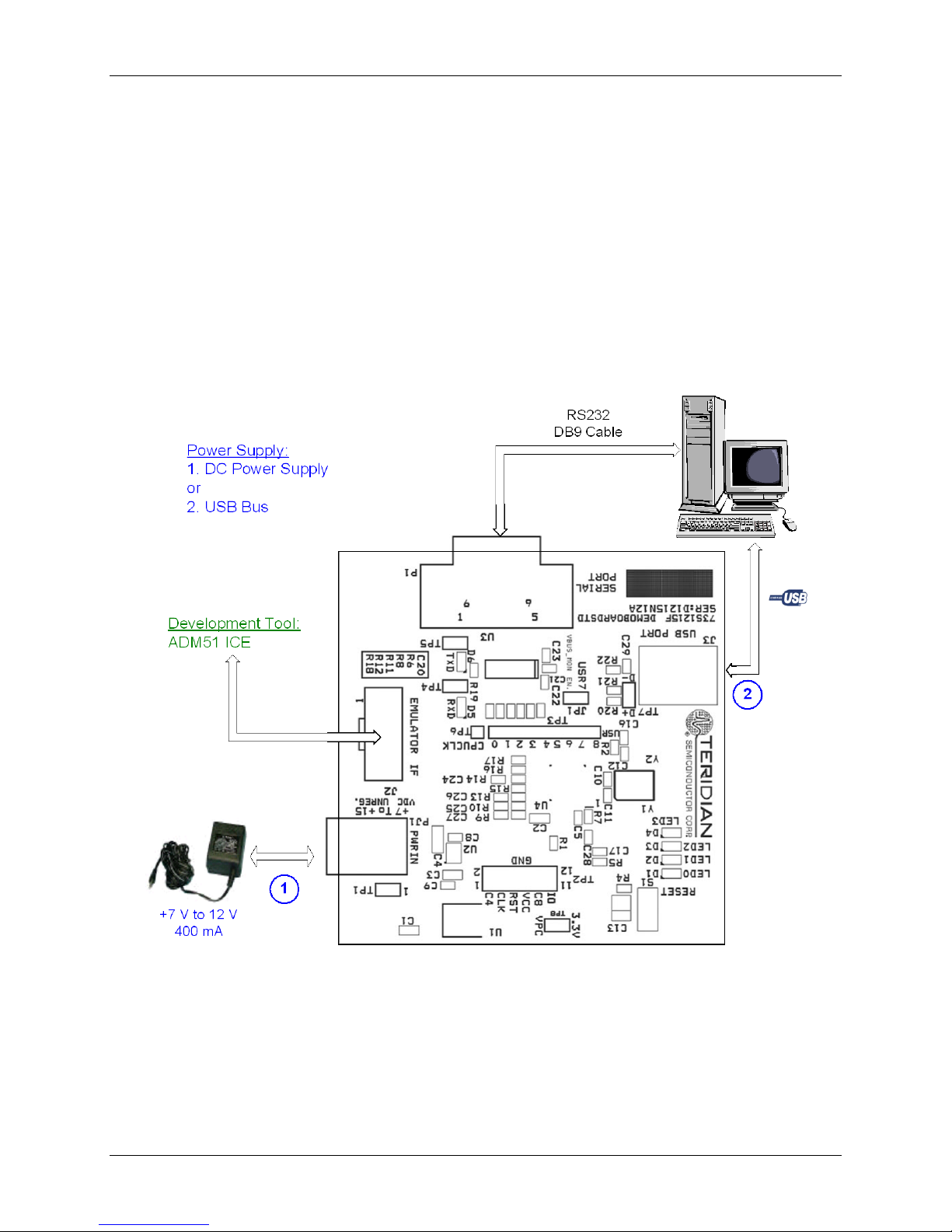
Figure 2 shows the basic connections of the Evaluation Board-Lite with the exter nal equi pment.
The power supply can come from any AC-DC co nverter block able to generate a D C power suppl y of 7 V
min / 12 V max / 400mA connected to connector P J1.
The communicat i on with an external host can be accommodated by either:
• A standard USB 2.0 Full Spe ed Interfa ce or
• A st andard RS-232 serial interface (TX/R X onl y).
The boar d pr ov i des by default the USB CCID application. Refer to Section 3 for inform ation to set up and
run the USB CCID application.
Figure 2: 73S1215F Evaluation Board Lite Basic Connections
Rev. 1.1 7
73S1215F Evaluation Board Lite User Guid e UG_1215F_045
2.1 Connecting the Evaluation Board Lite with an Emulation Tool
The 73S1215F Evaluation Board Lite can operate with an In-Circuit-Emulator (ICE) from Signum Systems
(model AD M -51). The Signum System PO D has a ribbon cable that m ust b e di r ectly attach ed to
connector J2 (se e Figure 2).
Signum Systems offers different pod options depending on user needs. The standard pod al lows users to
perform typical emulator functi ons such as symbolic debugging, in-line breakpoints, memory examination
and/or modification , e tc. Othe r pod options enable code trace capabi lity and/or complex breakpoints at an
additional cost.
2.2 Loading User Code into the Evaluation Board Lite
Hardware Interface for Programming
The signals listed in Table 1 are necessary for communi cation between t he Flash Downl oader o r ICE and
the 73S1215F.
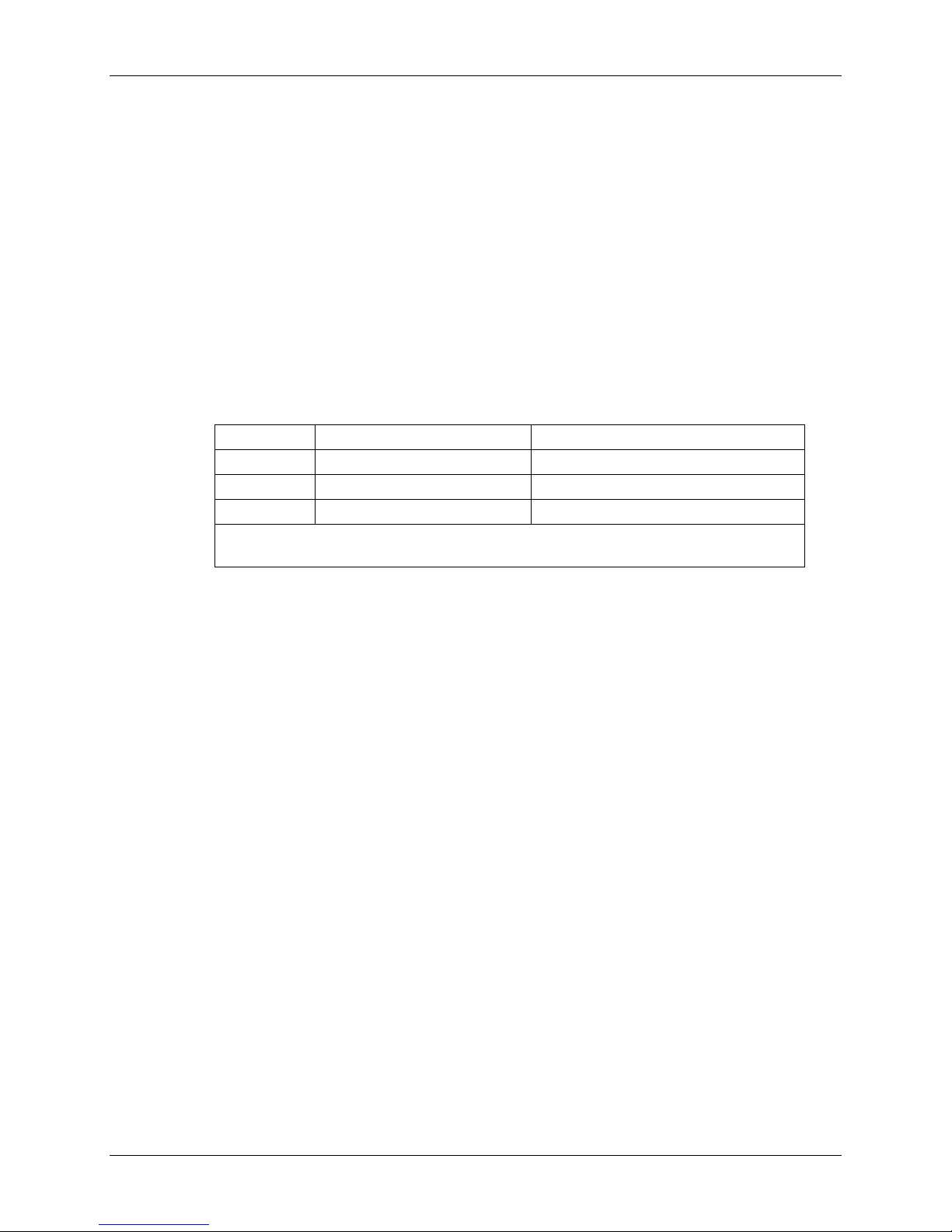
Table 1: Flash Programming Interface Signals
Signal Direction Function
E_TCLK Output from 73S1215F Data cl ock
E_RXTX Bi-directional Data input/output
E_RST1 Bi-directional Flash Downloader Reset (active low)
1
The E_RST signal should only be driven by the TFP2 when enabling these
interface signals. The TFP2 m ust release E_ R ST at all other times.
The signals in Table 1, al ong wit h 3.3 V and GND, are available on the emulator header J2. Production
modules may be equipped with much sim pler programming connectors, e.g. a 5x1 head er .
Programming of the flash memory requ ires eit her the Signum Systems ADM51 in-circui t emul ator or t he
TSC Flash Pr ogrammer Model TFP2 provided by Teridian.
Loading Code with the In-Circuit Emulator
If firmware exists in the 73S 1215F flash memory, the memory must be erased before loadi ng a new file
into memory. In or der to erase th e fl ash memory, the RESET button in the emu l ator software must be
clicked followed by th e ERASE butt on (see Figure 3).
Once the flash memory is er ased, a new file can b e l oaded using the Load command in the Fil e menu.
The dialog box shown in Figure 4 makes it possible to select the fil e to be loaded by cl icking the Browse
button. Once the fi l e is selected, pressin g the OK button loads the file into t he flash memory of t he IC.
At this point, the emul ator probe (cable) can be removed. Once the 73S1215F device is reset using the
reset button on the evaluation board , the n ew code st ar ts executing.
Loading Code with the TSC Flash Programmer Model TFP2
Follow the instructions given in the TSC Flash Programmer Model TFP2 User’s Manual.
8 Rev. 1.1
 Loading...