

Teridian 73S1209F User Manual

Simplifying System In tegrationTM
73S1209F
Evaluation Board User Guide
August 19, 2009
Rev. 1.3
UG_1209F_034

73S 1209F Evaluation Board User Guide UG_1209F_034
© 20 09 Teridi an Semiconductor C or porati on. All rights r eserved .
Teridian Semiconductor Corporation is a registered trademark of Teridian Semiconductor Corporation.
Simplifying System Integration is a trademark of Teridi an Semiconductor C or poration .
Microsoft, Windows and Vista are register ed trademar ks of Micr osoft Corporation.
Signum is a trademark of Si gnum Systems Corporation.
Keil i s a trademark of ARM® Ltd.
All other trademar ks are the pr operty of their respective o wn ers.
Terid i an Semiconductor Corporation m akes no warranty for the use of its p r oduct s, other than expressly
contained in the Company’s warr anty d etailed in the Terid ian S emiconductor Corporation st andar d Terms
and C onditions. The company assu mes no responsib i lity for any errors whi ch may appear in this
document, reserves th e r i ght to change device s or sp ecifications detailed herein at any time withou t
notice and does n ot make any commitm ent to upd ate the information contained herein. Accordingl y, the
reader is cautioned to verify that t his document is current by comparing it to the latest version on
http://www.teridian.com or by checking with your sales repres entative.
Terid i an Semiconductor Corp., 64 40 Oak Canyon, Suite 100, Ir vine, CA 92618
TEL (714) 508-8800, FAX (714) 508-8877, http://www.teridian.com
2 Rev. 1.3

UG_1209F_034 73S1209F Evaluation Board User Guide
Table of Contents
1
Introduction ................................................................................................................................... 4
1.1 Evaluat i on Ki t Contents ......................................................................................................... 5
1.2 Evaluat i on Board Feat ures .................................................................................................... 5
1.3 Recommended Equipment and Test Tools ............................................................................ 5
2 Evaluation Board Setup................................................................................................................. 6
2.1 Connecting the Evaluation Board with an Emulation Tool ...................................................... 7
2.2 Loading U ser Code i nto the Evaluati on Board ....................................................................... 8
3 Using the PCCID Application ...................................................................................................... 10
3.1 Host Demonstration S oftware Instal lation ............................................................................ 10
4 Evaluation Board Hardware Description .................................................................................... 11
4.1 Jumpers, Swit ches and Modules ......................................................................................... 11
4.2 Test Points ......................................................................................................................... 16
4.3 Schematic........................................................................................................................... 17
4.4 PCB Layouts....................................................................................................................... 18
4.5 Bill of Materials ................................................................................................................... 24
4.6 Schem atic Information ........................................................................................................ 27
4.6.1 Reset Circuit.............................................................................................................. 27
4.6.2 Oscillators ................................................................................................................. 27
4.6.3 LCD .......................................................................................................................... 28
4.6.4 Smart Card Interface ................................................................................................. 29
5 Ordering Information ................................................................................................................... 30
6 Related Documentation ............................................................................................................... 30
7 Contact Information ..................................................................................................................... 30
Revision H istory .................................................................................................................................. 31
Figures
Figure 1: 73S1209F Evaluation Board ..................................................................................................... 4
Figure 2: 73S1209F Evaluation Board Basic Conn ections
Figure 3: 73S1209F Evaluation Board Basic Conn ections with ADM-51 ICE
Figure 4: Emulator Window Showing RESET and ERASE Buttons
Figure 5: Emulator Wind ow Showing Erased Flash Memory and File Load Menu
Figure 6: 73S1209F Evaluation Board Jumper, S witch and Module Locations
Figure 7: 73S1209F Evaluation Board Electr i cal Schemat ic
Figure 8: 73S1209F Evaluation Board Top Vi ew (Silkscreen)
Figure 9: 73S1209F Evaluation Board Bot tom View (Silkscreen)
Figure 10: 73S1209F Evaluation Board Top Si gnal Layer
Figure 11: 73S1209F Evaluation Board Middle Layer 1 – Ground Plane
Figure 12: 73S1209F Evaluation Board Mid dle L ayer 2 – Supply Plane
Figur e 13: 73 S1209F Eva l ua tion Board Bottom Signal Layer
Figure 14: Extern al Components for RESET
Figure 15: Oscillator Circu it
Figure 16: LCD Connecti ons
Figure 17: Smart C ar d Con nect i ons
Tables
Table 1: Flash Programming Interface Signals ......................................................................................... 8
Table 2: Evaluation Board Jumper, Switch and Module Description
Table 3: Evaluation Board Test Point Description
Table 4: 73S1209F Evaluat ion B oar d Bil l of Mater ials
........................................................................ 6
............................................ 7
........................................................... 9
..................................... 9
........................................ 15
................................................................... 17
................................................................. 18
............................................................ 19
...................................................................... 20
................................................. 21
................................................. 22
................................................................. 23
.......................................................................................... 27
.................................................................................................................... 27
.................................................................................................................. 28
....................................................................................................... 29
....................................................... 11
................................................................................... 16
............................................................................ 24
Rev. 1.3 3
73S 1209F Evaluation Board User Guide UG_1209F_034
1 Introduction
The Teridian Semiconductor Corporation (TSC) 73S1209F Evaluat ion B oar d is use d to demonstrate the
capabilities of the 73S1209F Smart Card Cont r ol ler device. It has been desi gned to operate either as a
standalone or as a develop ment platform.
The 73S1209F Evaluation Board can be programmed to run any of the Teridi an turnke y appli cations or a
user-developed cust om application. Teridian provides its USB CCID application preloaded on the board
and an EMV testing application on t he CD.
Appli cations can be downloaded through the In-Circuit-Em ulator ( ICE) or through the TSC Flash
Programmer Mod el TFP2. As a developm ent tool, th e evaluation board can operate in conjunction with
an ICE to develop and debug 73S1209F based embedded applications.
The 73S1209F Evaluation Board uses the same PWB as the 73S1215F. The 73S1215F has
some features that the 73S1209F does not contain. Th ese include the 32 kH z oscillator, USB
interface, LED2 and LE D 3. These feat ures are depopulated on th e 73S1209F.
4 Rev. 1.3
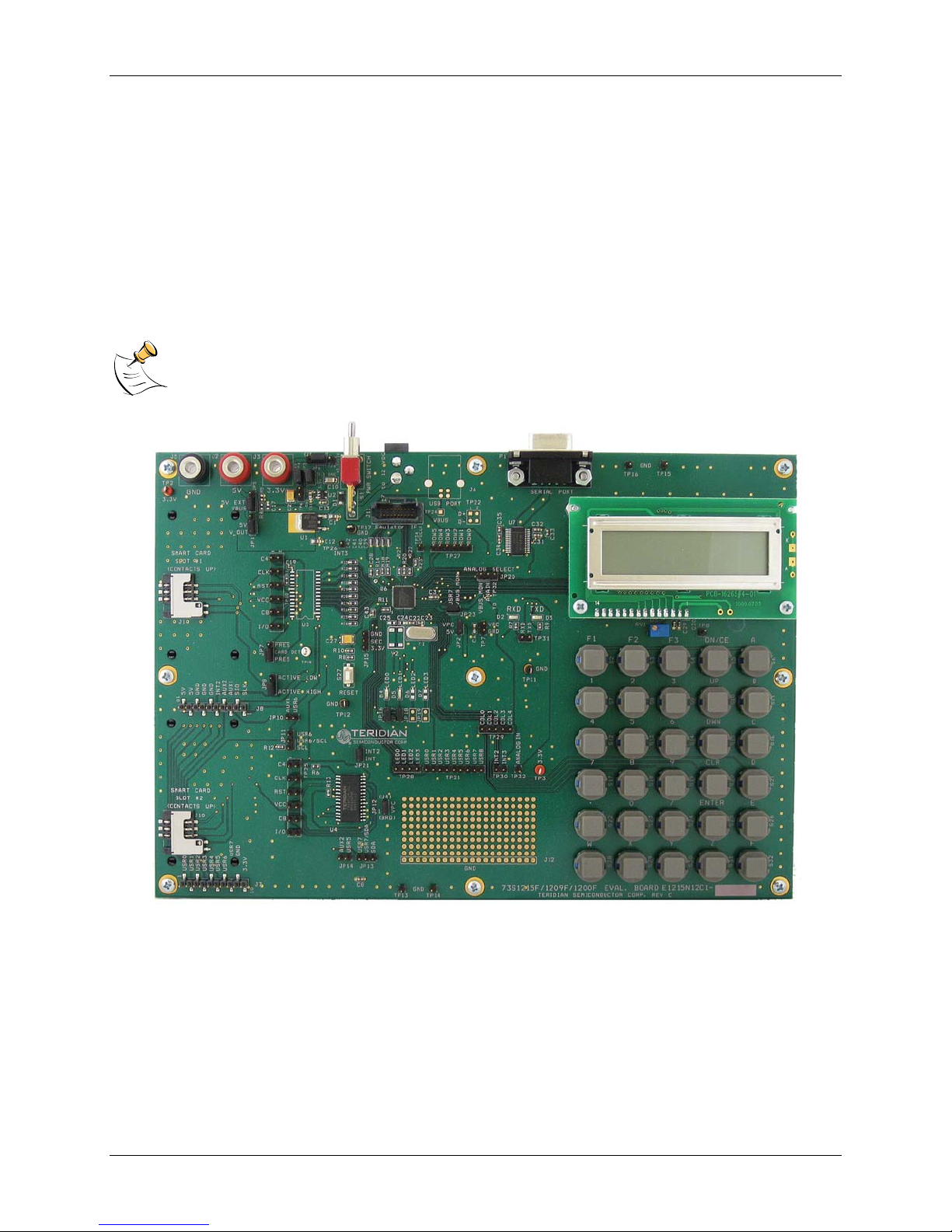
Figure 1: 73S1209F Evaluation Board

UG_1209F_034 73S 1209F Evaluation Board User Guide
1.1 Evaluation Kit Contents
The 73S1209F Evaluation Kit contains the following:
• 73S1209F Evaluation Boar d: 4-layer, r ectan gul ar PWB as shown in Figure 1 (identification n um ber
E12 15N12C1 Rev C), co ntainin g the 73S1209F with the preloaded turnkey program PCCID.
• 12 VDC/1,000 mA universal wall transformer with 2.1 mm plug ID (CUI Inc. – EPAS-101W-12).
• Serial cable: DB9, male/female, 2 meter length (Digi-Key AE1379-ND).
• CD containing d ocumentation (dat a sheet, and use r guides), Software API l ibraries, evaluation c ode,
and utilities.
1.2 Evaluation Board Fe atures
The 73S1209F Evaluation Board (see Figure 1) includes the following:
• RS-232 interface
• Dual smart card interface
• ICE/Programmer interface
• 2 line x 16 character LCD module
• 6 x 5 Keypad
• 2 LEDs
1.3 Recommended Equipment and Test Tools
The following equipment and tools ( not provided) are recommended for use with the 73S12 09F
Evaluation Kit:
• For functional evaluation: PC with Microsoft® Windows® XP or Vista®.
• For software devel opm ent (MPU code)
Signum™ ICE (In C ircuit Emulator): ADM-51 . R efer to
http://signum.temp.veriohosting.com/Signum.htm.
Keil™ 8051 C Compiler Kit: CA 51. Refer to http://www.keil.com/c51/ca51kit.htm and
http://www.keil.com/product/sales.htm
Rev. 1.3 5
73S 1209F Evaluation Board User Guide UG_1209F_034
RS232
DB9 Cable
+7 V to +12 V
400 mA
Power Supply:
1) Lab DC dual (3.3 V,
5 V) supply
or
2) Non-regulated DC
Block
1
2
+2.7 V to
+3.6 V
400 mA
+4.0 V to
+6.5 V
400 mA
2 Evaluation Board Setup
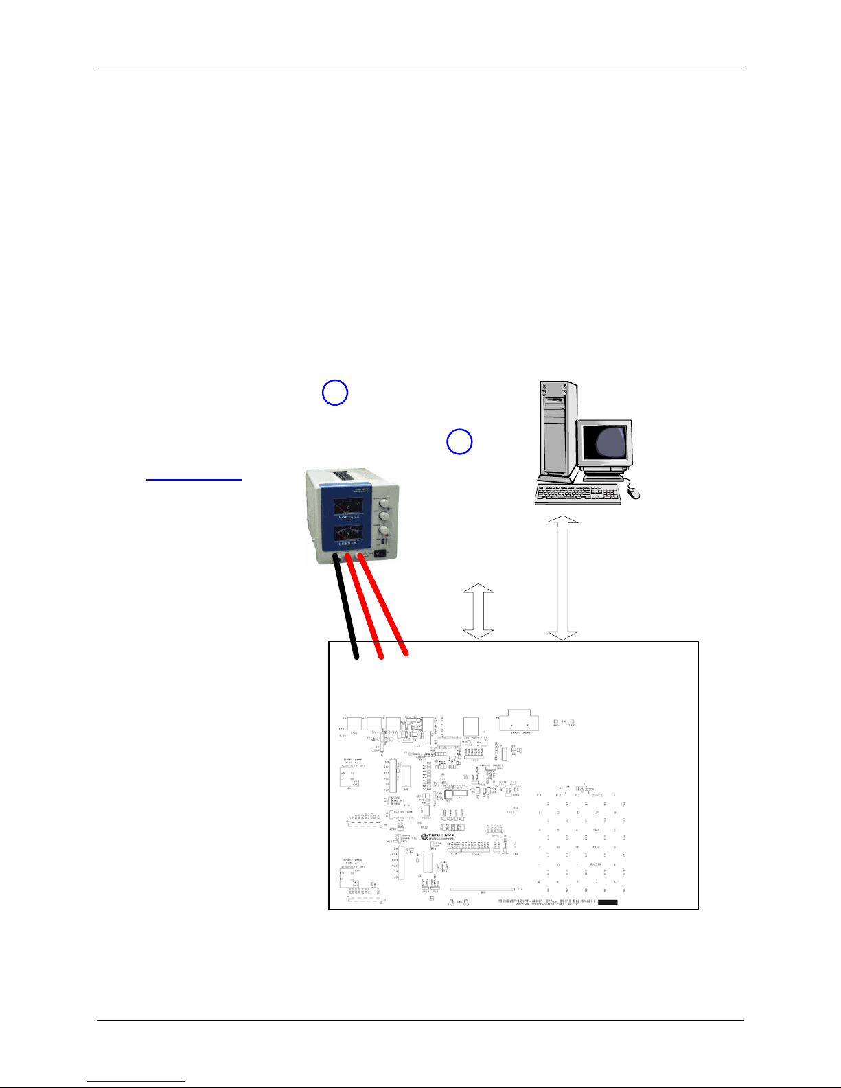
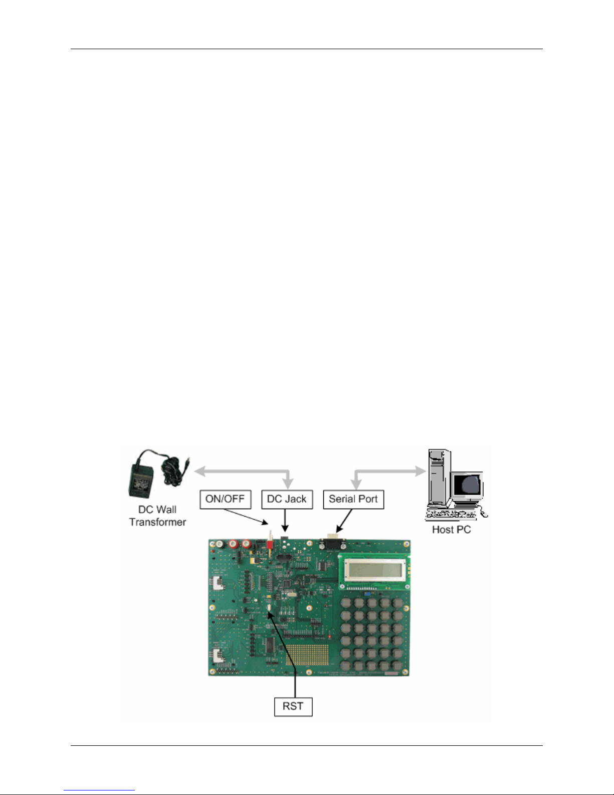
Figure 2 shows the basic connect i ons of t he evaluation board wit h the extern al equi pm ent.
The power supply can come from two sources:
• A regulated lab power supply connected to the banana p lugs J2, J3 and J5 . In th is case, the board
main switch S1 has no effect.
• Any AC-DC converter block ( default), able to generate a DC power supply of 7 V mi n / 12 V max /
400 mA. In this case, the board main switch S1 connects or di sconnects the supply to the board.
The communicat i on with an external host is accommodated via a standard RS-232 serial interface
(TX/RX only).
The board is loaded by default wit h the PCCID application. It requir es a PC to be connected through its
serial port. When powered-up, the board is able to run with the PC Exerciser h ost ap plica tion. Refer to
the 73S1209F Evaluat ion Board Quick Start Guide to setup and run the PCCID application.
Figure 2: 73S1209F Evaluation Board Basic Connections
6 Rev. 1.3
UG_1209F_034 73S 1209F Evaluation Board User Guide
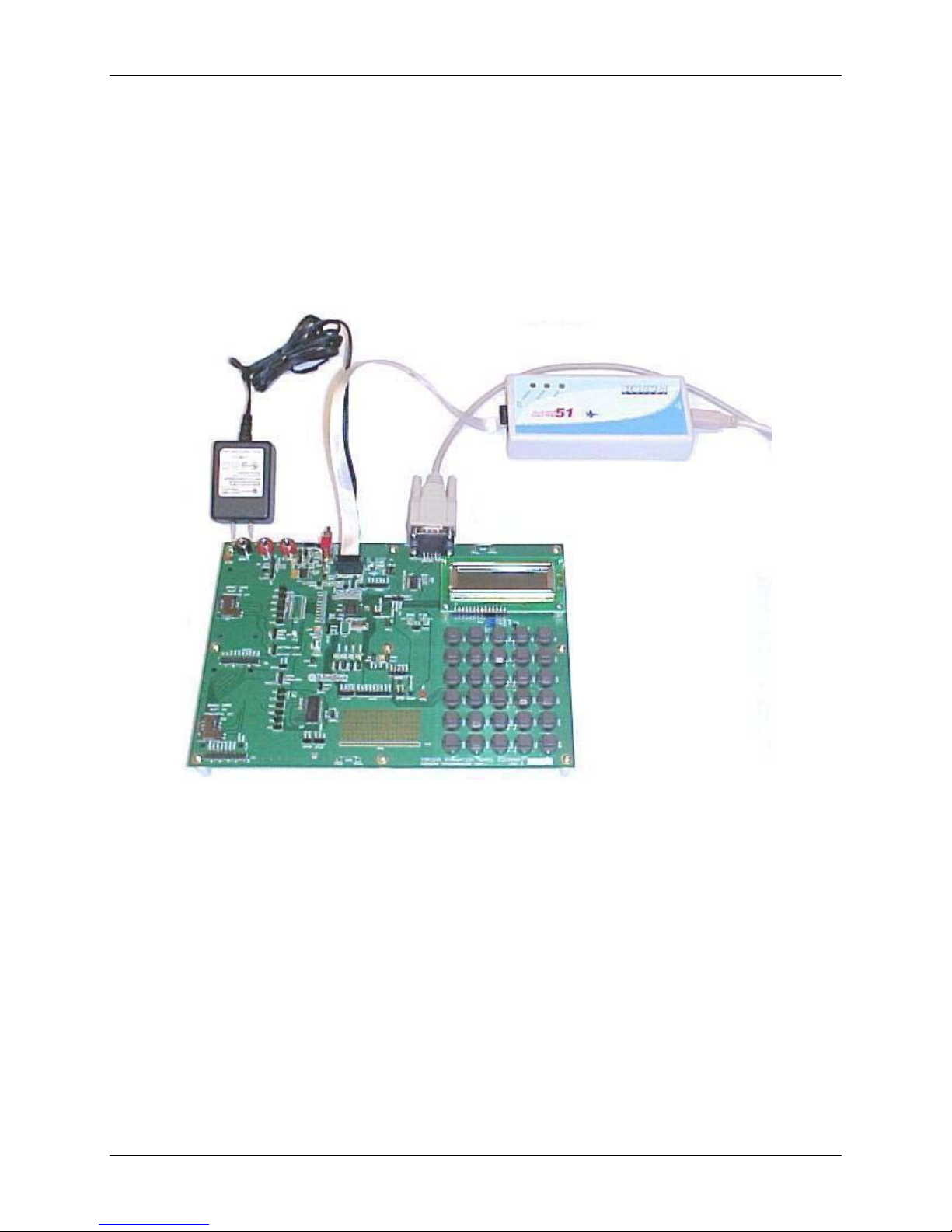
2.1 Connecting the Eval uat ion Bo ard wit h an Emu lat ion Tool
The 73S1209F Evaluation Board has been designed to operate with an In-Circuit-Emulator (ICE) from
Signum Systems (model ADM-51). Figure 3 shows the connection s between the ICE and the evaluation
board. The Si gnum System POD has a ribbon cable that mu st be direct ly attached to co nnector J11.
Signum Systems offers d ifferent POD options d epending on user needs. The standard pod all ows use r s
to per form typical emulator functi ons such as sy m bolic debugging, in-line breakpoin ts, memory
examination/modification, etc. Oth er pod options en able code trace capabilit y and/or complex
breakpoin ts at an addi tional cost.
Figure 3: 73S1209F Evaluation Board Basic Connec tions with ADM-51 ICE
Rev. 1.3 7
73S 1209F Evaluation Board User Guide UG_1209F_034
1
2.2 Loading User Code into the Evalu ati on B oard
Hardware Interface for Programming
The signals listed in Table 1 are necessary for communi cation between t he TFP2 or IC E and the
73S1209F.
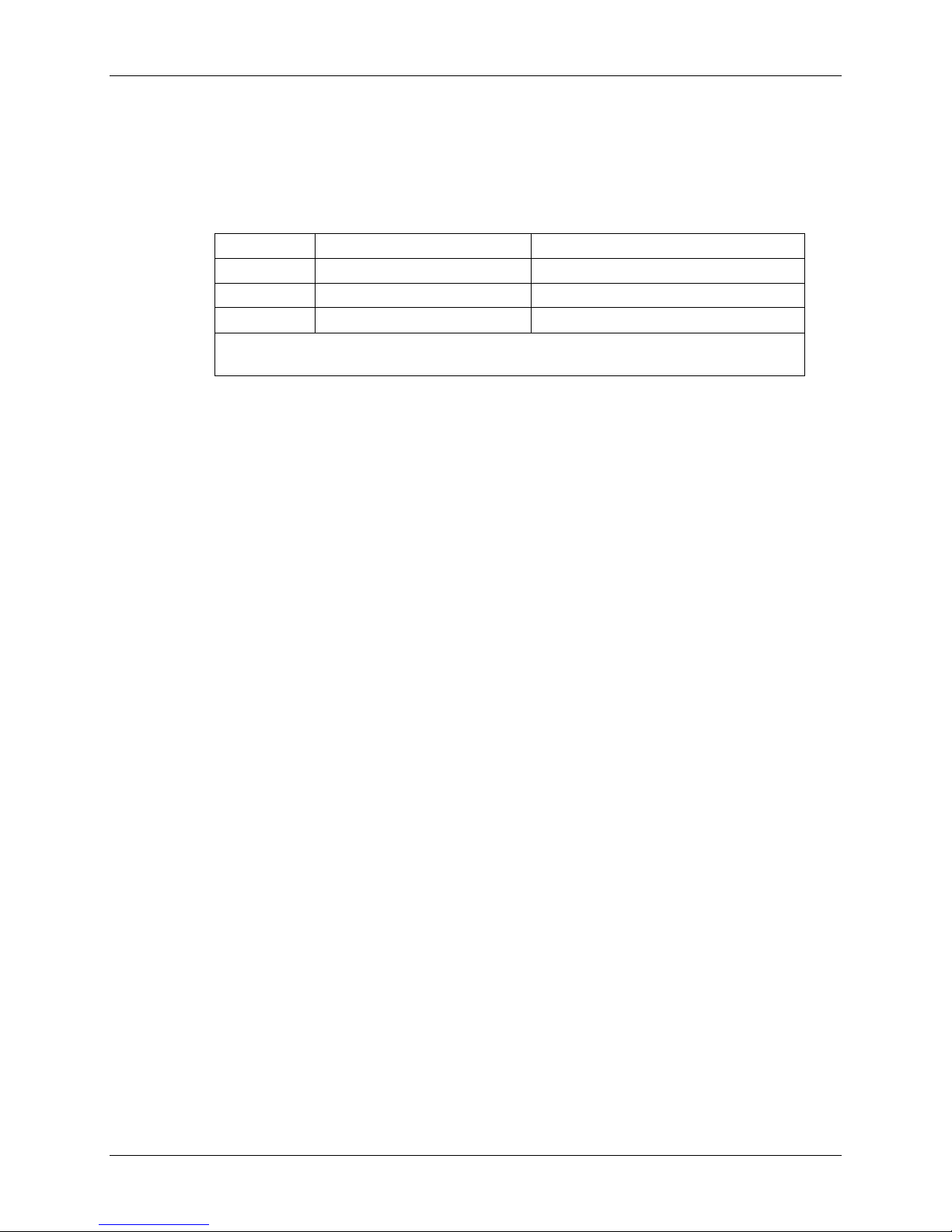
Table 1: Flash Programming Interface Signals
Signal Direction Function
E_TCLK Output from 73S1209F Data cl ock
E_RXTX Bi-directional Data input/output
E_RST1 Bi-directional Flash Downloader Reset (active low)
The E_RST signal should only be driven by the TFP2 when enabling these
interface signals. The TFP2 m ust release E_ R ST at all other times.
These signals, along with 3.3 V and GND ar e available on the em ulator header J11. Production modules
may be equi pped wit h much simpler prog r am ming connectors, e.g . a 5x1 h eader.
Programming of the flash memory requires either the S ignum Systems ADM51 in-circuit emulator or the
TSC Flash Pr ogrammer Model TFP2 provided by Teridian.
Loading Code with the In-Circuit Emulator
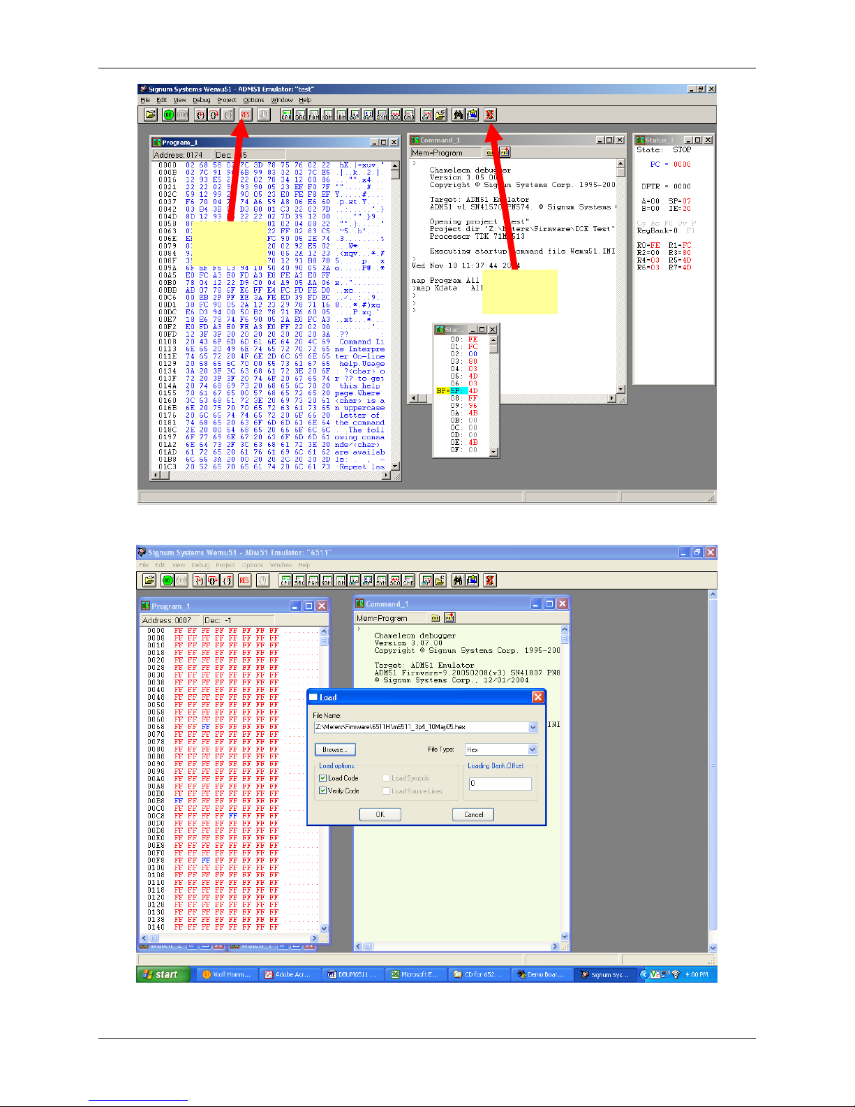
If firmware exists in the 73S 1209F flash m emory, the memory must be erased befo r e l oadin g a new file
into memory. In or der to erase th e fl ash memory, the RESET button in the emu l ator software must be
clicked followed by th e ERASE butt on (see Figure 4).
Once the flash memory is erased, the new file can be load ed using the Load command in the File m enu.
The dialog box shown in Figure 5 makes it possibl e to select the file to be loaded by clicking the Browse
button. Once the file is selected, pressi ng the OK button loads th e fi l e into the flash memory of the IC.
At this point, the emul ator probe (cable) can be removed. Once the 73S1209F device is r eset using the
reset button on the evaluat ion board, the new code starts executi ng.
Loading Code with the TSC Flash Programmer Model TFP2
Follow the instructions given in the TSC Flash Programmer Model TFP2 User's Manual.
8 Rev. 1.3
UG_1209F_034 73S 1209F Evaluation Board User Guide
RESET
BUTTON
ERASE
BUTTON
Figure 4: Emulator Window Showing RESET and ERASE Buttons
Figure 5: Emulator Window Showing Erased Flash Memory and File Load Menu
Rev. 1.3 9
73S 1209F Evaluation Board User Guide UG_1209F_034
3 Using the PCCID Application
The PCCID firmware is pre-installed on the 73S1209F Evaluation Board. It requ ires a PC with the se r ial
RS-232 port. When powered-up, the board is ab le to r un the PCCID demonstration h ost application which
allows:
• Smart card act ivation and deactivation, in ISO or EMV mode.
• Smart card APDU com mands to be exchang ed with the smart ca r d inserted in the board.
• Star ting a test sequence in or der to test and evaluate the board performance against an EM V test
environment.
3.1 Host Demonstration Software Installation
Installation on Windows XP
Follow these step s to install the soft w are on a PC ru nning W i ndows XP:
• Extract “PCCID Vz.zz Release.zip” (where z.zz is the latest versi on of the firmware release).
o Create an install dir ectory. F or example: “C:\TSC\”.
o Unzip “PCCID V z.zz Release.zip” to the just created folder. All ap plications and documen tation
need ed to run the board with a Windows PC will be loaded to th is folder .
• Plug the suppli ed adapter in to the 5V DC jack and a wall ou tlet.
• Connect the serial cable between the host syst em and the 73S1209F Evaluation Board.
• Press the ON/OFF switch to turn the board on.
• Run “TSCP-CCID.exe” (located in the path - x:\yyy\ PCCID Vz.zz Release\Host
Applications\Windows A pp \App\Bin\Release) on the host syst em to execute the host demonstr ation
app l ication (where x refers to the drive, yyy refers to the direct or y t he in stallation .zip file was
expanded to and z.zz is the l atest version of the fir mware release).
At this point th e application window should appear. For addi tional information regarding the use of the
Terid i an Host application, refer to t he Pseudo-CCID Host GUI Users Guide (UG_12xxF_037).
10 Rev. 1.3
 Loading...