

Page 1
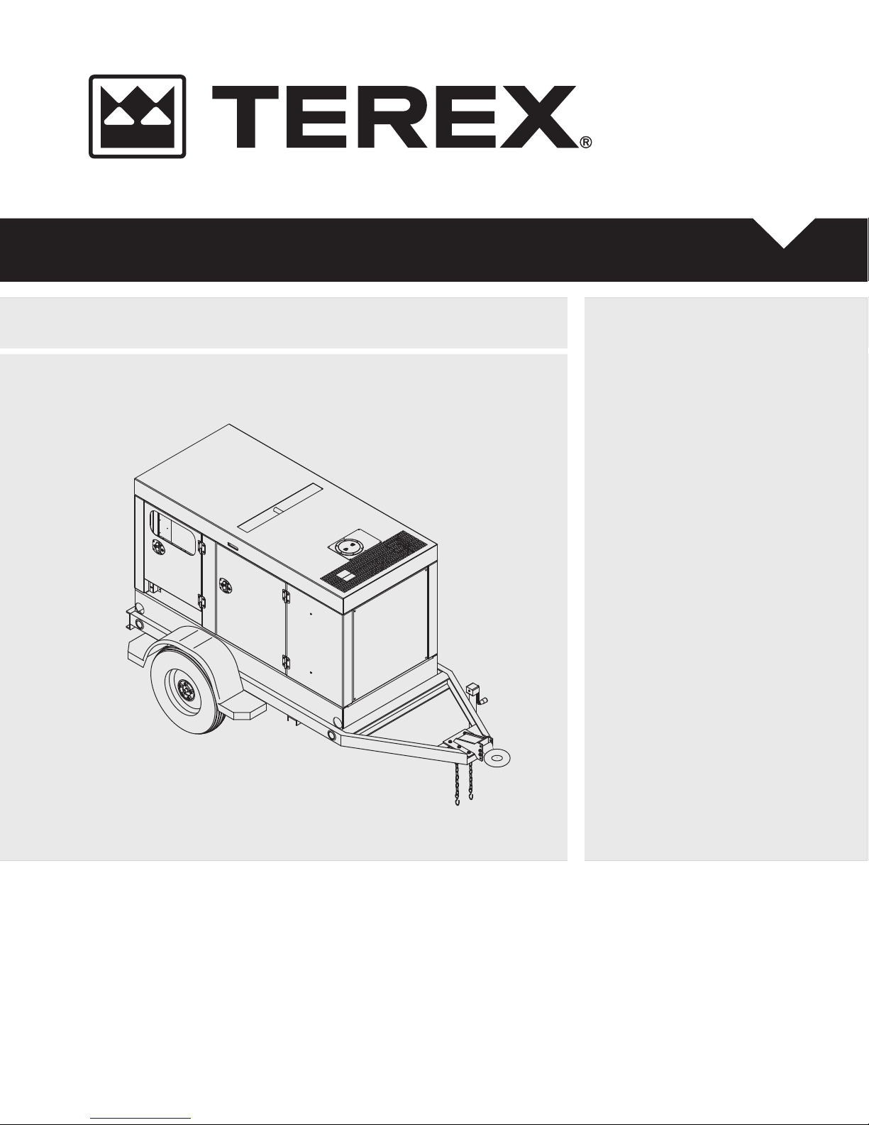
Operator/Service & Parts Manual
T50
First Edition
Rev A1
Part No. 833009
Page 2
Serial Number Registration
Serial Number Registration............................................................................... 4
Introduction
Introduction....................................................................................................... 5
Description of Equipment.................................................................................. 5
Operator's Manual
Table Of Contents
General Safety
Operating Instructions
Hazard Classification ........................................................................................ 6
Safety Sign Locations ....................................................................................... 7
Accident Prevention.......................................................................................... 8
Unauthorized Welding....................................................................................... 8
Fueling.............................................................................................................. 8
Electrical Safety ................................................................................................ 9
Battery Hazards................................................................................................ 9
Beware of Traffic Hazards ................................................................................ 9
Receipt of Delivery Checklist .......................................................................... 10
Transport & Towing ........................................................................................ 11
Setup .............................................................................................................. 11
Starting the Engine/Generator Set .................................................................. 13
Loading Instructions........................................................................................ 14
Voltage Selector Switch Operation ................................................................. 14
Potentiometer (Voltage Adjustment) ............................................................... 16
Murphy Cascade Controller ............................................................................ 16
Dynagen Auto Start Engine Controller ............................................................ 16
Woodward Speed Controller ........................................................................... 16
2 T50 Super Quiet Generator Part No. 833009
Page 3

Operator's Manual
Operating Instructions (Continued)
Overcurrent Protection.................................................................................... 17
Shutdown Procedures .................................................................................... 17
Wet Stacking .................................................................................................. 18
Torque Specifications
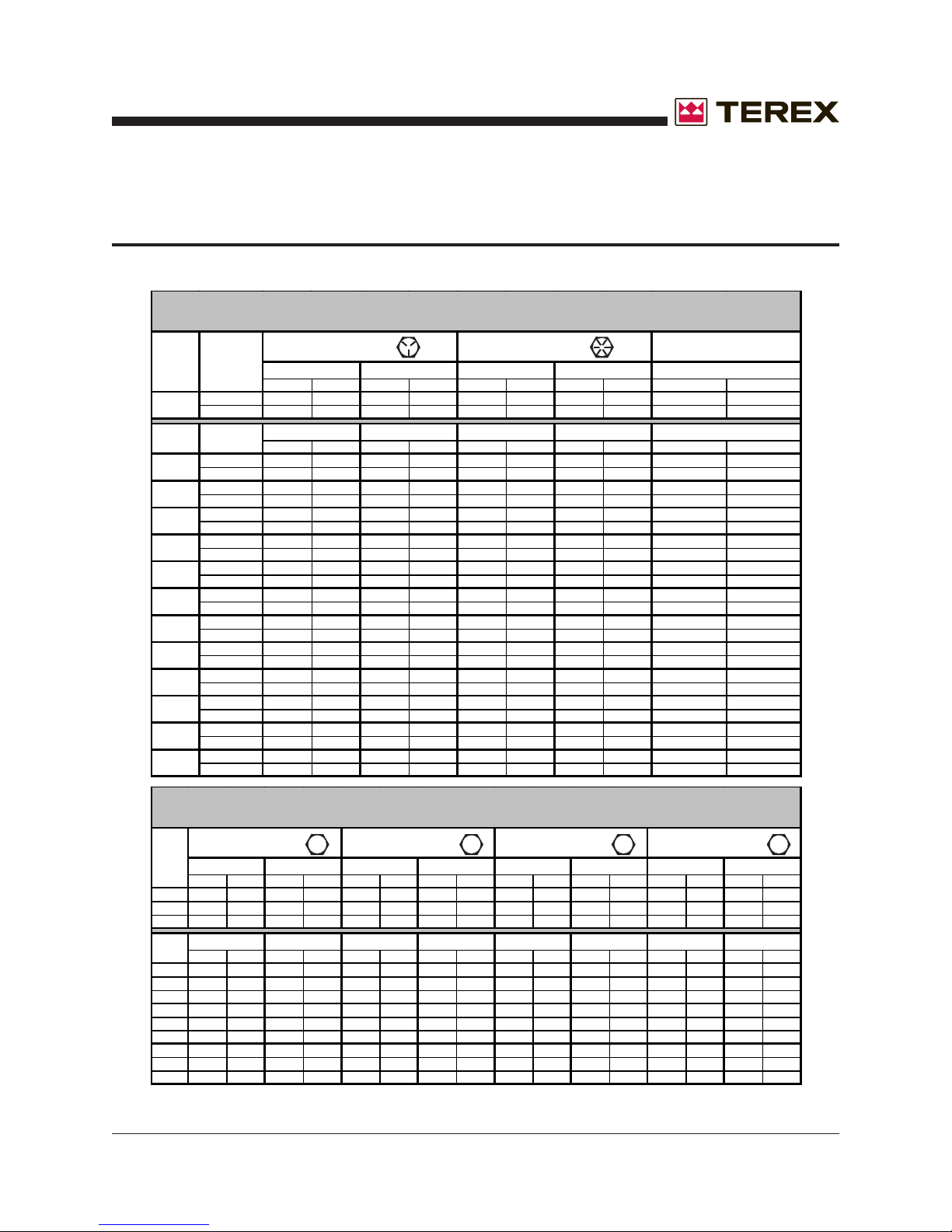
SAE Fastener Torque Chart ........................................................................... 19
Metric Fastener Torque Chart......................................................................... 19
Generator Torque Specifications .................................................................... 20
Part No. 833009 T50 Super Quiet Generator 3
Page 4
Operator's Manual
SERIAL NUMBER REGISTRATION
TEREX Model Number _____________________ Serial Number ____________________________
Engine Model Number______________________ Serial Number ____________________________
Generator Model Number ___________________ Serial Number ____________________________
Owner:__________________________________ Ship to: _________________________________
Options:_________________________________
_______________________________________
_______________________________________
_______________________________________
_______________________________________
This Operation and Service Manual contains information specifically pertaining to the operation and
maintenance of the TEREX Super Quiet Generators. We suggest that you read this manual carefully prior
to operating the generator. This manual should be retained and refered to for operation, maintenance and
ordering parts. When ordering parts, PLEASE INCLUDE THE MODEL AND SERIAL NUMBER located
on the nameplate of the generator . For major repair and service or other information, contact your
TEREX dealer, or call or write to:
P.O. Box 3147 (29732)
590 Huey Road
Rock Hill, SC 29730
Telephone: (800) 433-3026
FAX: (803) 366-1101
4 T50 Super Quiet Generator Part No. 833009
Page 5
Operator's Manual
INTRODUCTION
Owners, Users, and Operators:
TEREX appreciates your choice of our product for
your application. Our number one priority is user
safety which is best achieved by our joint efforts.
We feel that you can make a major contribution to
safety if you as the equipment users and operators:
• Comply with OSHA, Federal, State, and Local
Regulations.
• Read, Understand, and Follow the
instructions in this and other manuals supplied
with this product.
• Use Good, Safe Work Practices in a common
sense way.
• Only have trained operators — directed by
informed and knowledgeable supervision —
operating this product.
If there is anything in this manual that is not clear
or which you believe should be added, please
send your comments to TEREX Service Department in Rock Hill, SC.
The engine is equipped with a 12-volt starter and
can be wired for remote starting capability at the
control panel.
A dry-element air cleaner is standard equipment to
ensure a clean air supply, and a remote fuel/water
separator is included for additional fuel system
protection.
A governor on the engine provides a stable
operating speed under varying load conditions,
and the generator is equipped with a solid-state
voltage regulator to stabilize the output voltage
under these same conditions. Figures and
schematics of both the governor and regulator are
provided in the ENGINE and GENERATOR
OPERATOR’S MANUALS.
An automatic shutdown system is incorporated in
the generator set to sense low oil pressure and/or
high coolant temperature, and in either case the
engine/generator assembly will automatically
cease operation.
A diesel fuel tank is incorporated within the base
of the unit to ensure an uninterrupted operating
cycle under full load. The engine/generator
assembly is mounted to the base using high
durometer vibration isolators.
THE SAFETY ALERT SYMBOL IS USED TO
ALERT YOU TO POTENTIAL PERSONAL
INJURY HAZARDS. OBEY ALL SAFETY
MESSAGES THAT FOLLOW THIS SYMBOL
TO AVOID POSSIBLE INJURY OR DEATH.
DESCRIPTION OF EQUIPMENT
The engine/generator assembly consists of a
diesel engine combined with an electrical generator. This assembly is firmly bolted together to form
an integral unit and does not require anything
other than routine maintenance.
Part No. 833009 T50 Super Quiet Generator 5
The enclosure for the generator set is constructed
from 12 or 14-gauge sheet metal to ensure
maximum rigidity, and is bolted together to allow
easy access to major components if necessary.
Four lockable, hinged access doors are provided
for routine operation and maintenance.
The enclosure on the Super Quiet Generator is
specifically designed for a high degree of sound
attenuation. This allows the generator set to be
operated in noise-sensitive environments. The
interior of the enclosure is coated with sounddampening polymer foam that is highly effective in
noise suppression.
A high ambient temperature radiator and a critical
grade exhaust silencer are contained within the
enclosure as standard equipment.
Page 6
DESCRIPTION OF EQUIPMENT (Cont.)
A center-point lifting attachment is located in the
top of the enclosure to allow crane lifting of the
entire unit.
Operator's Manual
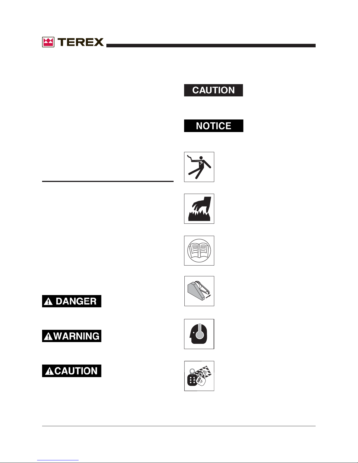
Yellow without safety
alert symbol - Indicates a
situation which, if not avoided, may result in
property or equipment damage.
The generator set is mounted on a trailer equipped
for highway operation. Hydraulic surge brakes are
standard on larger generator sets for maximum
stopping efficiency. Electric brakes are also
available as an option.
GENERAL SAFETY
HAZARD CLASSIFICATION
A multi-tier hazard classification system is used to
communicate potential personal injury hazards.
The following signal words used with the safety
alert symbol indicate a specific level of severity of
the potential hazard. Signal words used without
the safety alert symbol relate to property damage
and protection only. All are used as attentiongetting devices throughout this manual as well as
on decals and labels fixed to the machinery to
assist in potential hazard recognition and prevention.
Red - Indicates an
imminently hazardous
situation which, if not avoided, will result in death
or serious injury.
Green - Indicates important installation, operation
or maintenance information.
Hazardous voltage. Will cause
serious injury or death.
Hot exhaust. Can contain carbon
monoxide. Will cause serious injury
or death.
Read all manuals that shipped with
your equipment. Maintenance is
done more easily and safely when
you know what you're doing.
Keep all guards in place.
Orange - Indicates a
potentially hazardous
situation which, if not avoided, could result in
death or serious injury.
Yellow with safety alert
symbol - Indicates a
potentially hazardous situation which, if not
avoided, may result in minor or moderate injury.
6 T50 Super Quiet Generator Part No. 833009
Wear hearing protection when you
are near this equipment.
Lockout and Tagout. Equipment may
be energized. Lockout and tagout all
energy sources prior to performing
maintenance adjustments.
Page 7
Operator's Manual
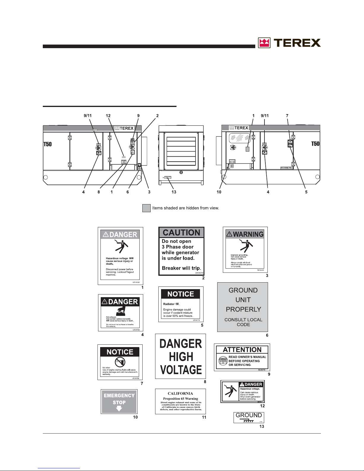
SAFETY SIGN LOCATIONS
GENERAL SAFETY (Cont.)
Part No. 833009 T50 Super Quiet Generator 7
Page 8
GENERAL SAFETY (Cont.)
Operator's Manual
ACCIDENT PREVENTION
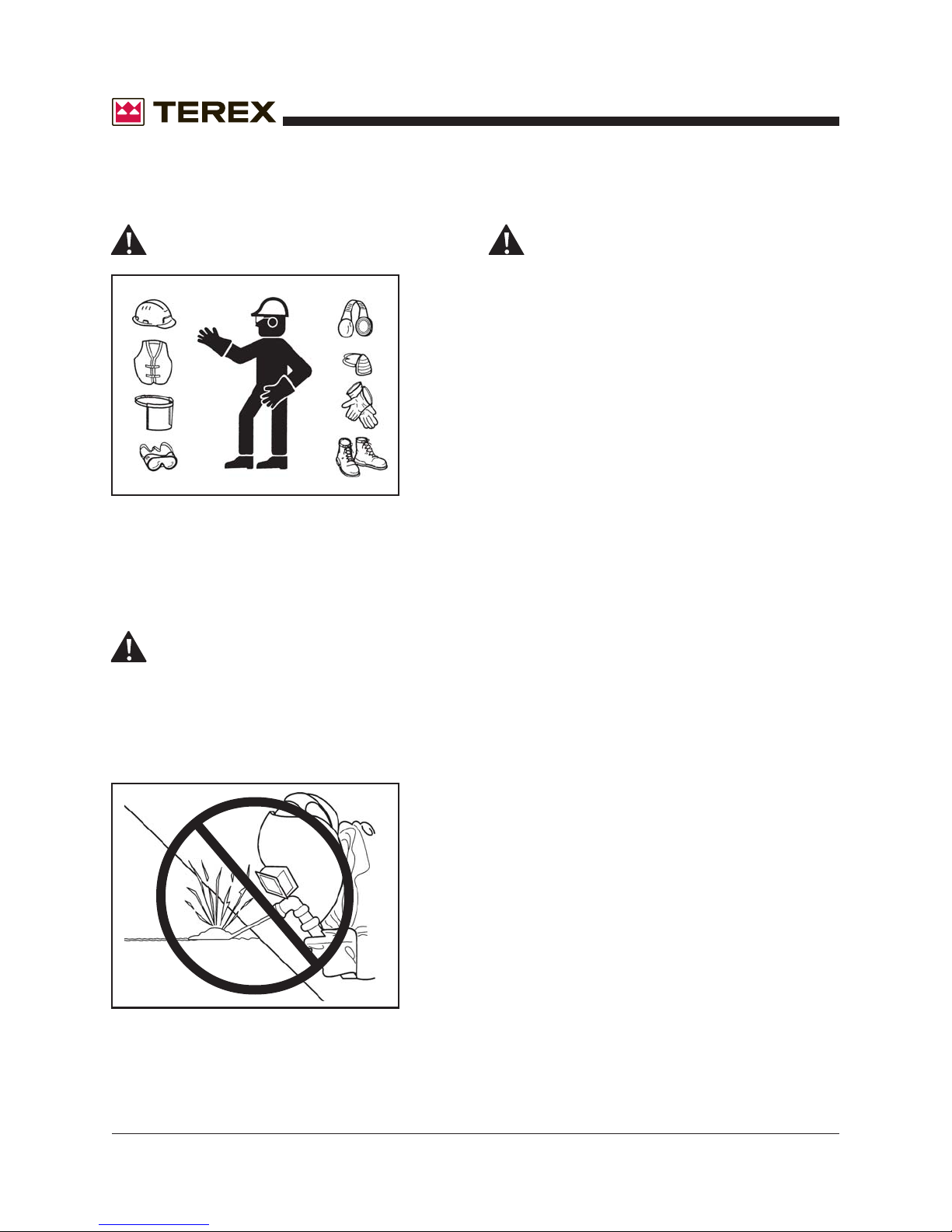
Use protective clothing and safety equipment.
Always wear approved safety equipment such as
gloves, safety boots, safety hard hat, goggles, ear
protection, and dust masks when necessary.
Wear protective clothing that is snug and belted
where required.
UNAUTHORIZED WELDING
UNAUTHORIZED WELDING CAN CAUSE
STRUCTURAL FAILURE OR PERSONAL
INJURY.
DO NOT weld on any structural member.
FUELING
ALWAYS handle fuel with care. It is highly
flammable.
ALWAYS stop engine before refueling. Fill
fuel tank outdoors.
DO NOT replace fuel lines with materials
different from those supplied as original
equipment.
FIRES CAN CAUSE SEVERE PERSONAL
INJURY OR MACHINE DAMAGE.
Prevent fires by keeping the generator and its
surrounding area clean.
DO NOT refuel while smoking or when near
open flame or sparks.
DO NOT refuel the engine when it is hot.
Allow to cool for several minutes before
refueling.
DO NOT spill fuel inside the engine compartment.
If fuel has leaked, wipe it up and have leak
repaired before next use.
Any unauthorized welding or repair procedure
will void the warranty.
8 T50 Super Quiet Generator Part No. 833009
ALWAYS Have a fire extinguisher nearby. Be
sure the extinguisher is properly maintained and
be amiliar with its use. Extinguishers rated ABC
by the NFPA are appropriate for all applications.
EXHAUST GASES ARE TOXIC. DO NOT USE
INDOORS UNLESS PROPERLY VENTILATED
OR AN EXHAUST SCRUBBER IS USED.
Check exhaust system regularly for leaks and
ensure that the exhaust manifolds are secure and
not warped. Make sure the unit is well ventilated.
Page 9
Operator's Manual
GENERAL SAFETY (Cont.)
ELECTRICAL SAFETY
THIS EQUIPMENT USES HIGH VOLTAGE CIRCUITS CAPABLE OF CAUSING SERIOUS INJURY OR DEATH. EXERCISE EXTREME CAUTION
AROUND ANY ELECTRICAL COMPONENT
WHILE OPERATING THIS UNIT.
Always ground the unit according to local
codes. A grounding lug is provided for your
convenience.
Beware of cut or damaged power cords. Have a
qualified electrician replace any damaged cords
immediately.
DO NOT TOUCH HOT PARTS.
The exhaust manifold and tail pipe are very hot.
Parts of the engine are also hot. Use protective
gloves when handling hot parts.
BATTERY HAZARDS
DO NOT remove the vent caps when charging the
battery.
Always wear eye protection when servicing the
battery.
If acid gets on skin or eyes, immediately flush
under running water and obtain medical
attention.
KEEP ALL BODY PARTS AND CLOTHING
AWAY FROM MOVING PARTS.
Loose jackets, shirts, sleeves, jewely and especially neckties should not be worn while working
on or running the unit.
Only remove guards or protective devices from
unit temporarily to gain access for maintenance.
Always replace guards immediately after servicing. Never remove guards while unit is operating.
Keep your hands away from moving parts, particularly clear of the radiator fan and alternator belts
when the engine is running.
LEAD ACID BATTERIES CAN BE DANGEROUS. THE SULFURIC ACID IN THE BATTERY
CAN CAUSE SEVERE SKIN AND EYE BURNS.
THE HYDROGEN GAS EMITTED DURING
CHARGING CAN EXPLODE IF AN ARC OR
FLAME IS PRESENT.
DO NOT smoke while servicing the battery.
DO NOT allow tools to touch battery terminals and
create an arc.
Disconnect the negative terminal of the battery
when working on the engine or other parts to
prevent accidental arcing. Disconnect the negative
cable at the end away from the battery.
Part No. 833009 T50 Super Quiet Generator 9
Stand clear of traffic when starting or checking the
unit along the road.
Check the fuel tank, oil pan, and fuel and oil lines
for leaks that would spill fuel or oil on the road.
Check fasteners and mounting brackets periodically to insure all are tight and nothing is in danger
of falling off during transit.
BEWARE OF TRAFFIC HAZARDS
Page 10
GENERAL SAFETY (Cont.)
Operator's Manual
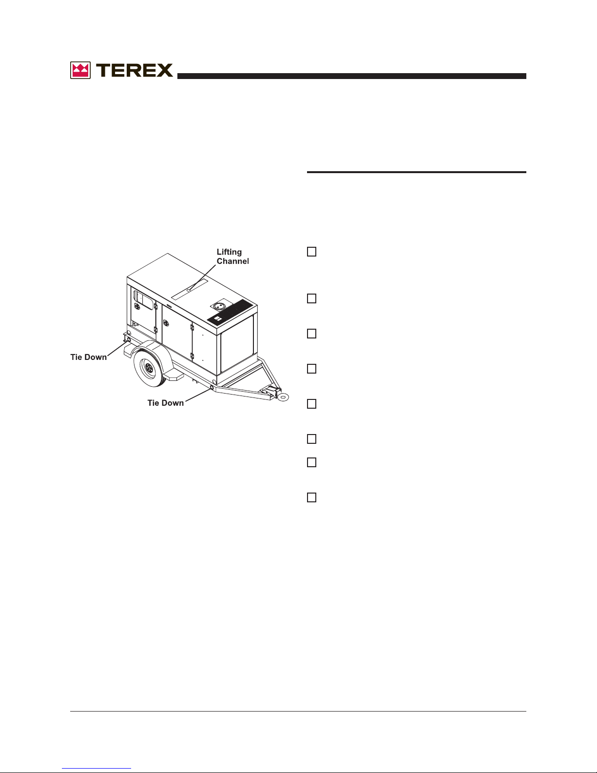
BE CAREFUL WHEN LIFTING. NEVER SUSPEND ANY OTHER EQUIPMENT FROM THE
SHIPPING TIE DOWNS.
Use the lifting eye for lifting the trailer (with cabinet). Make sure any tie-downs at the bottom of the
trailer are released prior to lifting.
RECEIPT OF DELIVERY
CHECKLIST
The generator will be serviced, tested and ready
for operation upon delivery. Terex recommends
the following checks:
Insure there is no freight handling damage
which should be charged against the
carrier.
Check the front jack for security and proper
operation.
Check that the tires are not damaged, under
inflated or that any lugs are loose.
Check the engine/generator for obvious
damage, loose connections, or leaks.
Check the control panel for damage or loose
connections.
Check the exhaust system for damage.
NEVER CLIMB ON TOP OF THE CABINET.
10 T50 Super Quiet Generator Part No. 833009
Check all fluid levels; battery, radiator, and
engine oils.
Ensure manuals are in the pocket provided
inside the unit.
Page 11
Operator's Manual
TRANSPORT & TOWING
All trailer-mounted Terex Super Quiet generators
are designed for highway and off road towing
capability. Please consult state and local transportation codes before transporting the generator set.
Additionally, all state and local traffic laws take
precedence over the following instructions whenever differences arise between them.
• Make sure the towing vehicle is of adequate
size to both tow and stop the unit.
• Disconnect all wiring and cabling (including the
ground wire) from the generator set.
GENERAL SAFETY (Cont.)
• Check the tires for proper inflation and verify
that the lug nuts are tight.
• If equiped with towing lights, connect the
electrical coupler to the towing vehicle.
• Observe posted speed limits for trailers.
Generally, do not exceed 45 mph on paved
roads and 10 mph on unpaved roads.
EXCEEDING THESE RECOMMENDED SPEEDS
CAN CAUSE SEVERE DAMAGE TO THE UNIT.
DAMAGE CAUSED BY THESE
UNSAFE PRACTICES WILL VOID THE MANUFACTURER’S WARRANTY.
• Close and latch or lock all access doors.
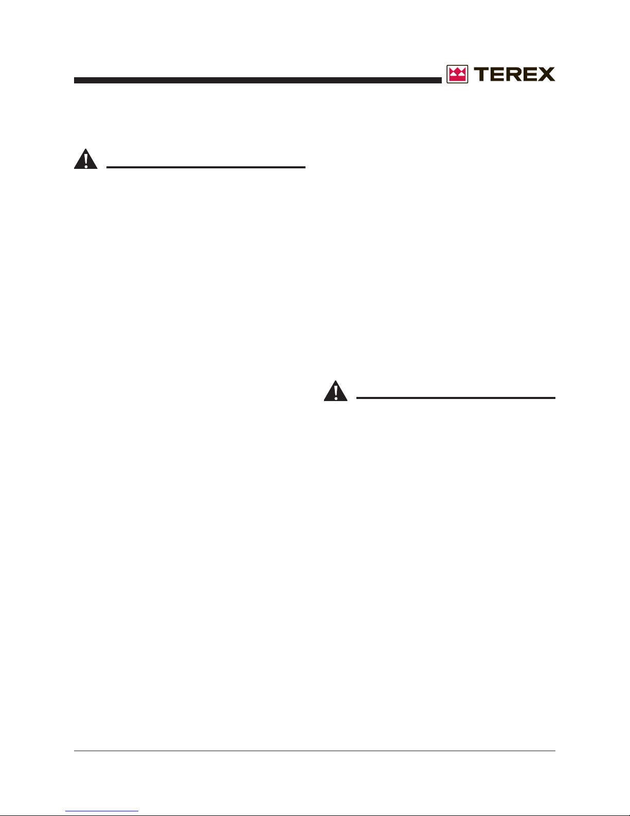
• Using the front leveling jack, raise the trailer
hitch to an adequate height so that the
generator can be securely attached to the
transporting vehicle.
• Ensure that the coupler is properly secured to
the towing vehicle and attach the safety chains.
Attach the “breakaway” chain on the surge
brake and the electrical coupler if these options
are included on the unit.
ALWAYS USE THE PROPER TRAILER HITCH
AND SAFETY CHAINS. OBEY ALL
LOCAL OR STATE D.O.T. LAWS WHEN TOWING A GENERATOR.
FAILURE TO PROPERLY SECURE THE TRAILER TO THE TOWING VEHICLE MAY
RESULT IN SERIOUS INJURY OR DEATH.
• Retract the front leveling jack into its stowed
position.
SETUP
Move the generator set to the desired location
keeping the following in mind:
• The spot where the generator set is positioned
should be relatively level.
• The location selected should be centrally
located to equipment requiring the loads to
minimize voltage drop in the power cord.
• Locate so power cords can be routed without
crossing roads and access routes.
• Locate where the engine will get good
ventilation. Do not locate where fumes will enter
a building.
• Do not place beside a building wall that would
reflect and intensify noise.
Unhitch from the towing vehicle as follows:
• Locate the generator set in the desired location.
Part No. 833009 T50 Super Quiet Generator 11
Page 12
SETUP (Cont.)
• If the axle is sloped downhill, turn the generator
set so that the axle is level.
Operator's Manual
NEVER REMOVE THE RADIATOR CAP WHILE
THE ENGINE IS RUNNING OR WHILE THE
ENGINE IS HOT.
• ALWAYS chock the wheels of the generator
set.
• Unhook hitch, safety chains and running lights.
• Rotate the tongue jack into position (90
degrees), release the hitch pin and raise the
tongue off the towing vehicle.
• Level the generator set with the tongue jack.
THE WHEELS MUST BE PROPERLY CHOCKED
IF THE GENERATOR IS ON UNLEVEL
GROUND. DO NOT OPERATE THE GENERATOR SET UNTIL IT HAS BEEN PROPERLY SECURED.
When preparing to start the generator set, follow
the sequence listed below:
• Check the oil level in the engine crankcase, and
add as required.
USE CLASS API, CC OR CD GRADE ENGINE
OIL. REFER TO THE ENGINE MANUFACTURER'S MANUAL FOR VISCOSITY AND QUANTITY.
• If the battery is not a maintenance free battery,
check the electrolyte level in the battery and
add distilled water if necessary.
• Check fuel/water separator for water in the fuel
system. Drain water from separator if
necessary.
• Check fuel level in the fuel tank and add as
required. Check to insure the fuel tank vent is
“open” and not clogged.
USE #2 DIESEL FUEL ONLY.
• Verify that the generator main circuit breaker is
in the “OFF” position.
• Make sure the generator set is properly
grounded. This is accomplished by connecting
the grounding lug provided at the rear of the
generator set enclosure to a mechanical
earthground with a minimum 2/0 size #4 bare
electrical cable. If this differs from your local
code, always follow the local code for
grounding.
THIS GENERATOR SET PRODUCES VOLTAGES THAT CAN CAUSE SEVERE SHOCK OR
DEATH! ONLY QUALIFIED ELECTRICIANS
SHOULD PERFORM ELECTRICAL WORK.
• Check the coolant level in the radiator, and add
as necessary. If adding coolant, use only a
50/50 mixture of antifreeze and water. Refer to
your engine manufacturer's maintenance
manual for specific antifreeze information.
12 T50 Super Quiet Generator Part No. 833009
Page 13
Operator's Manual
OPERATING INSTRUCTIONS
STARTING THE ENGINE/
GENERATOR SET
NEVER ATTEMPT TO START THE GENERATOR SET WITH ANY OF THE CIRCUIT BREAKERS "ON". THESE BREAKERS ARE LOCATED
ON THE DISTRIBUTION PANEL. STARTING
WITH THE BREAKERS "ON" CAN CAUSE
DAMAGE TO THE GENERATOR.
Once setup procedures are completed, the
generator set is ready to be started. Start the
unit according to the following steps:
• Make sure the GENERATOR VOLTAGE
SELECTOR SWITCH has been set to the
proper range.This switch should be located
above the 3-phase distribution panel.
(DISREGARD IF THE UNIT DOESN’T HAVE
A SELECTOR SWITCH. THIS UNIT IS
PRESET FOR ONE VOLTAGE. SEE NAME
TAG.)
NEVER CHANGE THE POSITION OF THE
VOLTAGE SELECTOR SWITCH WHILE THE
GENERATOR IS RUNNING! THIS WILL
RESULT IN IMMEDIATE DAMAGE TO THE
SWITCH, THE GENERATOR, OR THE
CONNECTED EQUIPMENT. IT MAY RESULT
IN SERIOUS INJURY TO THE OPERATING
PERSONNEL.
For Cascade Equipped Generators:
• Place the toggle switch in "ON" position then
press the MANUAL ("MAN") BUTTON on the
Cascade Controller. Make sure all debris and
obstructions have been cleared from moving
parts and electrical terminals. The generator will
only make 3 attempts at starting before it must
be reset with the switch.
For DynaGen Equipped Generators:
• If the unit is equipped with a DynaGen controller
place the toggle switch in the “MANUAL”
position to start the engine. If the engine fails to
start, the “NO SPEED SIGNAL” led will light.
Return the toggle switch to the “OFF” position
then back to the “MANUAL” position. If the
engine fails to start again refer to the DynaGen
manual or call Terex service. The “AUTO”
position is to be used only with the remote start
feature.
• Now that the generator set is running, allow five
minutes for warm-up time.
• Listen for any unusual sounds or excess
vibrations that could signal problems and
require immediate shutdown of the unit. Should
unusual sounds be detected, shut the unit
down, and contact TEREX Service.
• Once the engine has been started and running
smoothly, the following gauges should be
monitored. All gauges are located on the control
panel.
• Oil Pressure Gauge - This gauge should read
30 psi or higher.
• Coolant Temperature Gauge -This gauge
should read between 170-200 degrees F.
• Voltmeter - This gauge should read at least 12
volts DC to indicate the diesel engine’s
alternator is charging properly.
• AC Voltmeter - This gauge should reflect the
proper voltage selected for this operation.
• AC Ammeter - The reading on this gauge
should be zero since the main breaker is in the
“OFF” position. Once a load is applied to the
generator, the ammeter will produce an
appropriate reading.
Part No. 833009 T50 Super Quiet Generator 13
Page 14
OPERATING INSTRUCTIONS (Cont.)
LOADING INSTRUCTIONS
To make the electrical hookup to the generator
set, observe the following set of procedures:
SHUT DOWN THE GENERATOR SET BY
PRESSING THE "OFF" BUTTON ON THE CASCADE CONTROL PANEL. SWITCH THE TOGGLE TO THE “OFF” POSITION BEFORE MAKING ANY ELECTRICAL CONNECTIONS. THE
MAIN GENERATOR BREAKER SHOULD BE IN
THE “OFF” POSITION.
• Shut down the generator set.
• Connect the desired electrical apparatus to the
generator set, while making sure no other
power source is connected to the same
apparatus.
• Restart the engine and monitor the gauges as
outlined in the "Operating Instructions" section
under "Starting the Engine/Generator Set".
• Turn the required generator circuit breakers to
the “ON” position.
Operator's Manual
The needle on the ammeter will deflect to the right
temporarily and then return to a normal
reading if the unit is operating properly.
VOLTAGE SELECTOR SWITCH
OPERATION
The TEREX Super Quiet generator sets rated
from T25I to the T280J are equipped with a
VOLTAGE SELECTOR SWITCH. This switch can
have three positions marked “480/277” and “208/
120”, or “240/120”. Each position delivers a
different output voltage to the DISTRIBUTION
LUGS. The SELECTOR SWITCH and DISTRIBUTION LUGS are located on the DISTRIBUTION PANEL. The following instructions should
be considered when operating the VOLTAGE
SELECTOR SWITCH.
• Always make sure the voltage selector switch
has been set to the desired range before
starting the generator set.
THIS GENERATOR SET PRODUCES VOLTAGES THAT CAN CAUSE SEVERE SHOCK OR
DEATH! ONLY QUALIFIED ELECTRICIANS
SHOULD PERFORM ELECTRICAL WORK.
• Monitor the AC Ammeter - If the needle deflects
severely to the right and stays there,
immediately turn the required generator circuit
breakers to the “OFF” position.
SEVERE DEFLECTION OF THE AMMETER
INDICATES A WIRING PROBLEM OR AN
OVERLOAD PROBLEM. CONTINUED OPERATION UNDER THIS CONDITION WILL CAUSE
DAMAGE TO THE GENERATOR AND/OR
CONNECTED APPARATUS.
14 T50 Super Quiet Generator Part No. 833009
NEVER OPERATE THE VOLTAGE SELECTOR
SWITCH WHILE THE GENERATOR IS RUNNING! THIS WILL RESULT IN IMMEDIATE
DAMAGE TO THE SWITCH, THE GENERATOR,
OR THE CONNECTED EQUIPMENT WHICH
WILL ALSO VOID THE WARRANTY. IT MAY
RESULT IN SERIOUS INJURY TO THE OPERATING PERSONNEL.
Page 15
Operator's Manual
OPERATING INSTRUCTIONS (Cont.)
VOLTAGE SELECTOR SWITCH
OPERATION
• The voltage selector switch can control the
single-phase receptacles provided on the unit.
Their indicated voltages should be checked
after selecting the setting of the switch. The Y
voltage configurations of 480 and 240 will have
a voltage of 139 on the GFI receptacles.
The voltage selector switch will have three positions, and each position gives a different output to
the three-phase distribution lugs (designated as
“L1”, “L2”, “L3”, and “N”) located on the distribution panel.
In the three-phase “480/277” position, the following will be the normal output voltages:
• Line - to - Line (“L1” to “L2”, “L2” to “L3”,
“L1” to “L3”) 480 VAC/3P.
• Line - to - Neutral (“L1”, “L2” or “L3” to “N”)
277 VAC/1P.
NOTICE: This three-phase wiring configuration
is referred to as “Hi Wye”.
In the three-phase “208/120” position, the following will be the normal output voltages:
• Line - to - Line (“L1” to “L2” and “L2” to
“L3”; “L1” to “L3”) 240 VAC/3P.
THIS EQUIPMENT USES HIGH VOLT-
AGE CIRCUITS CAPABLE OF CAUSING
SERIOUS INJURY OR DEATH! EXCERCISE EXTREME CAUTION AROUND ANY ELECTRICAL
COMPONENT WHEN OPERATING THIS UNIT.
The three position selector switch has HI WYE
480 V 3ph., LOW WYE 240 V 3ph. and 240V
single phase that is Zig Zag. The following is the
output voltages on the zigzag position.
• Line 1-to-L3 240 VAC/1P.
• Line-to-Neutral 120 VAC/1P L2 is not used in
this position.
Once the required voltages are known, then the
combination of the proper switch position and
voltage adjustment potentiometer allows for fine
tuning the voltage to the exact needs of the
application.
ONCE THE PROPER VOLTAGE SELECTOR
SWITCH POSITION IS SELECTED, TEREX
HIGHLY RECOMMENDS THAT THE SWITCH
BE PADLOCKED IN THAT POSITION. THIS
PREVENTS THE SWITCH FROM BEING
MOVED WHILE THE UNIT IS OPERATING OR
BY UNAUTHORIZED PERSONNEL. DAMAGE
TO THE UNIT AND ANY CONNECTED EQUIPMENT WILL BE AVOIDED.
• Line - to - Neutral (“L1”, “L2”, or “L3” to
“N”) 139 VAC/1P.
NOTICE: This three-phase wiring configuration
is referred to as “Lo Wye”.
NOTICE: The above voltages can be “dialed
down”, or adjusted lower, by using the voltage
adjustment potientiometer located on the generator main control panel.
Part No. 833009 T50 Super Quiet Generator 15
Page 16

OPERATING INSTRUCTIONS (Cont.)
Operator's Manual
DO NOT OPERATE THE UNIT UNLESS
VOLTAGE HAS BEEN CHECKED AT
THE RECEPTACLES. CALL TEREX SERVICE IF
YOU HAVE ANY QUESTIONS.
INSTALLATION AND ANY WORK PERFORMED
ON THIS UNIT SHOULD BE DONE ONLY BY A
QUALIFIED ELECTRICIAN.
DO NOT REMOVE OR COVER ORIGINAL
SAFETY AND OPERATION DECALS. REPLACE
ANY DAMAGED DECALS BEFORE USING THIS
EQUIPMENT!
POTENTIOMETER (VOLTAGE
ADJUSTMENT)
The potentiometer is set at the factory. However, if
the voltage reading on the voltmeter is not as
desired use the following procedure to make the
necessary adjustments. With the unit running,
under no load, observe the AC voltmeter. Locate
the voltage adjustment knob on the control panel.
The decal above the knob indicates the direction
to turn the knob to increase or decrease the
voltage. Turning the knob to the right increases
the voltage while turning the knob to the left
decreases the voltage. Slowly turn the adjustment
knob in the desired direction, while observing the
AC voltage meter, stop when the desired voltage
is obtained. The unit is now ready to load. If the
desired voltage cannot be reached contact the
TEREX Service Department at 1-800-433-3026.
DYNAGEN AUTO START ENGINE
CONTROLLER
For generators with the DynaGen Controller
installed refer to the "DynaGen Installation and
User Manual for the ES51/52 Auto Start Engine
Controller" (Terex part number 833012) supplied
with the unit for configuration and operation.
WOODWARD SPEED CONTROLLER
For generators with the Woodward Speed Controller installed refer to the "Woodward Manual LCS
Series Integrated Speed Control p/n 37101S1"
(Terex part number 833013) supplied with the unit
for configuration and operation.
MURPHY CASCADE CONTROLLER
For generators with the Murphy Cascade Controller installed refer to the "Cascade Controller
Installation and Operations Manual p/n 00-020594" (Terex part number 833011) supplied with
the unit for configuration and operation.
16 T50 Super Quiet Generator Part No. 833009
Page 17
Operator's Manual
OPERATING INSTRUCTIONS (Cont.)
OVERCURRENT PROTECTION
This relay is mounted behind the control panel and
monitors the current draw and uneven current
draw to protect the generator set. This trip setting
is set at the factory with the proper kW using a
loadbank.
THIS SETTING SHOULD NEVER BE CHANGED
OR GENERATOR FAILURE WILL OCCUR.
The time delay setting is on the right side of the
relay and this setting may need to be adjusted. If
the overcurrent is tripping the time delay setting
needs to be turned clockwise a 1/4 turn. This
should correct the problem.
NOTICE: Call TEREX Service for wiring and
troubleshooting information.
SHUTDOWN PROCEDURES
NEVER SHUT THE UNIT DOWN WHILE
UNDER LOAD. THIS COULD CAUSE SERIOUS
INJURIES TO THE PERSON OPERATING THE
MACHINE OR DAMAGE THE GENERATOR.
NEVER SHUT THE UNIT DOWN WITH THE
MAIN GENERATOR CIRCUIT BREAKER IN THE
“ON” POSITION. THIS CAN CAUSE DAMAGE
TO THE GENERATOR AND/OR THE CONNECTED APPARATUS.
• Turn all generator breakers to the “OFF”
position.
• Allow the engine to run for 5 minutes under no
load until the coolant temperature gauge reads
approximately 175°F as a cool down cycle.
For Cascade Equipped Generators:
• Stop the engine by pushing the Cascade
Controller “OFF” button.
For DynaGen Equipped Generators:
• Stop the engine by switching the DynaGen
toggle switch to the “OFF” position.
Part No. 833009 T50 Super Quiet Generator 17
Page 18

Operator's Manual
WET STACKING
Wet-Stacking is a common problem with diesel
engines which are operated for extended periods
with light or no loads applied. When a diesel
engine operates without sufficient load, it will not
operate at its’ optimum temperature. This will allow
unburned fuel to accumulate in the exhaust
system, which can foul the fuel injectors, engine
valves and exhaust system, including turbochargers, causing the engine to run rough and reduce
the operating performance.
Wet Stacking does not usually cause any permanent damage and can be alleviated if additional
load is applied to relieve the condition. Applying an
increasing load until the excess fuel build up is
burned off and the system capacity is reached
usually can repair the condition.
A review of the appropriate equipment manuals is
important to understand fully the connection and
use of the load bank you choose for your maintenance and testing requirements.
Starting out using less than 25% of the nameplate
rating until the engine has warmed up. Progressively increase the load as the generator will allow
with out shutting down, and continue to run for 20
minutes per step. When you reach 80% of the
nameplate rating, run the generator for a minimum
of 45 minutes, or until the exhaust on the unit runs
clean. Allow the machine to fully cool down. Start
the unit again and load @ 80% for and additional
30 minutes. A full engine service is recommended
after this type wetstack burn off.
TEREX suggests a minimum load of 30 percent of
nameplate to prevent wet stacking, inversely
related to temperature (the lower the ambient
temperature the higher the minimum load).
TEREX recommends testing at least monthly for a
minimum of 30 minutes at not less than 80 percent
of nameplate rating. The proper installation and
use of a load bank can prevent loss of capacity
and increased maintenance caused by unburned
fuel due to wetstacking.
In the event you have a generator set that is
already wet stacked, it is recommended that the
load bank be used in progressive steps.
Assure the generator set is properly grounded and
connected to the load bank as instructed by the
manufacture. It is also recommended that the
generator be set at 240 VAC, 3 phase when doing
this test.
18 T50 Super Quiet Generator Part No. 833009
Page 19
Operator's Manual
SIZE THREAD
1/4
5/16
3/8
7/16
1/2
9/16
5/8
3/4
7/8
1
1.125
1.25
1.5
20
28
18
24
16
24
14
20
13
20
12
18
11
18
10
16
14
12
12
12
12
TORQUE SPECIFICATIONS
SA E FASTENER TORQUE CH ART
• T his chart is to be used as a gui d e on ly unless noted elsewh ere in t his man ual •
Grad e 5
in-lbs Nm in-lbs Nm in-lbs N m in-lbs N m in-lbs Nm
100 11.3 80 9 140 15.8 110 12.4 130 14.7
90 10.1 120 13.5 120 13.5 160 18 140 15.8
LUBED DRY LUBED DRY
ft-lbs Nm ft-lbs Nm ft-lbs Nm ft-lbs Nm ft-lbs Nm
13 17.6 17 23 18 24 25 33.9 21 28.4
14 19 19 25.7 20 27.1 27 36.6 24 32.5
23 31.2 31 42 33 44.7 44 59.6 38 51.5
26 35.2 35 47.4 37 50.1 49 66.4 43 58.3
37 50.1 49 66.4 50 67.8 70 94.7 61 82.7
41 55.5 55 74.5 60 81.3 80 108.4 68 92.1
57 77.3 75 101.6 80 108.4 11 0 149 93 126
64 86.7 85 115 90 122 120 162 105 142
80 108.4 110 149 120 162 150 203 130 176
90 122 120 162 130 176 170 230 140 189
110 149 150 203 160 217 210 284 180 244
130 176 170 230 180 244 240 325 200 271
200 271 270 366 280 379 380 515 320 433
220 298 300 406 310 420 420 569 350 474
9
8
7
7
6
320 433 430 583 450 610 610 827 510 691
350 474 470 637 500 678 670 908 560 759
480 650 640 867 680 922 910 1233 770 1044
530 718 710 962 750 1016 990 1342 840 1139
590 800 790 1071 970 1315 1290 1749 1090 1477
670 908 890 1206 1080 1 46 4 1440 1952 1220 1654
840 1138 1120 1518 1360 1844 1820 2467 1530 2074
930 1260 1240 1681 1510 2047 2010 2725 1700 2304
1460 1979 1950 2643 2370 3213 3160 4284 2670 3620
1640 2223 2190 2969 2670 3620 3560 4826 3000 4067
DRYLUBED
Grad e 8
A574 High Strength
Black Oxide Bolts
LUBEDDRYLUBED
LUBED
METRIC FASTENER TORQUE CHART
• T his chart is to b e u se d as a guide o nly unless n oted elsewh er e in this manual •
Size
(mm)
in-lbs Nm in- lbs N m in-lbs N m in-lbs N m in-lbs N m in-lbs N m in-lb s Nm in- lbs Nm
16 1.8 21 2.4 41 4.63 54 6.18 58 6.63 78 8.84 68 7.75 91 10.3
5
19 3.05 36 4.07 69 7.87 93 10.5 100 11.3 132 15 116 13.2 155 17.6
6
45 5.12 60 6.83 116 13.2 155 17.6 167 18.9 223 25.2 1.95 22.1 260 29.4
7
ft-lbs N m ft-lbs N m ft-lbs N m ft-lbs Nm ft-lbs N m ft-lbs N m ft-lbs Nm ft-lbs N m
5.4 7.41 7.2 9.88 14 19.1 18.8 25.5 20.1 27.3 26.9 36.5 23.6 32 31.4 42.6
8
10.814.714.419.627.937.837.250.539.954.153.272.246.763.362.384.4
10
18.9 25.6 25.1 34.1 48.6 66 64.9 88 69.7 94.5 92.2 125 81 110 108 147
12
30.1 40.8 40 54.3 77.4 105 103 140 110 150 147 200 129 175 172 234
14
46.9 63.6 62.5 84.8 125 170 166 226 173 235 230 313 202 274 269 365
16
64.5 87.5 86.2 117 171 233 229 311 238 323 317 430 278 377 371 503
18
91 124 121 165 243 330 325 441 337 458 450 610 394 535 525 71 3
20
124 169 16 6 225 331 450 442 600 458 622 612 830 536 727 715 970
22
157 214 21 0 285 420 570 562 762 583 791 778 1055 682 925 909 1233
24
* An anti-seize lubricant MUST be used on all stainless steel hardware.
Part No. 833009 T50 Super Quiet Generator 19
DRYLUBED
Class 10.9Class 8.8
LUBEDDRYLUBED
LUBED DRY LUBED DRYLUBED DRY LUBED DRY
10.9 12.98.84.6
DRY
Class 12.9Class 4 .6
LUBED DRY
Page 20
GENERATOR TORQUE SPECIFICATIONS
Generator FT*LB
Flex Plate to Flywheel 32-44
Generator Case to Bellhousing 60
1/2" Socket Head Cap Screws for Lifting Channel 126
1/2" Hex Head Screws for Lifting Channel 120
Genset Isolators 78
Operator's Manual
20 T50 Super Quiet Generator Part No. 833009
Page 21

October 2006
REV A
Service &
Parts Catalog
Part No. 833009 T50 Super Quiet Generator
Page 22
October 2006
Introduction
Important
Read, understand and obey the safety rules and
operating instructions in the appropriate Operator's
Manual on your machine before attempting any
maintenance procedure.
Basic mechanical, hydraulic and electrical
skills are required to perform most procedures.
However, several procedures require specialized
skills, tools, lifting equipment and a suitable
workshop. In these instances, we strongly
recommend that maintenance and repair be
performed at an authorized TEREX dealer
service center.
Technical Publications
TEREX Corporation has endeavored to deliver the
highest degree of accuracy possible. However,
continuous improvement of our products is a
TEREX policy. Therefore, product specifications
are subject to change without notice.
REV A
Serial Number Information
TEREX Corporation offers the following manuals
for these models:
Title Part No.
TEREX T50 Operator's/Parts Manual, ................ 833009
First Edition
Newage Generator Manual ................................. 830001
John Deere Engine Manual ................................ 839018
Perkins Engine Manual ....................................... 839019
Woodward Controls ............................................ 833013
DynaGen Controller Manual ............................... 833012
Cascade Controller Manual ................................ 833011
Dexter Axle Manual ............................................ 833014
Readers are encouraged to notify TEREX of errors
and send in suggestions for improvement. All
communications will be carefully considered for
future printings of this and all other manuals.
Contact Us:
www.TEREX.com
e-mail: [email protected]
Copyright © 2006 by TEREX Corporation
833009 Rev A October 2006
First Edition, First Printing
"TEREX" is a registered trademark of TEREX
Corporation in the USA and many other countries.
"Super Quiet" is a trademark of TEREX
Corporation.
Printed on recycled paper
Printed in U.S.A.
ii
T50 Super Quiet Generator Part No. 833009
Page 23
October 2006
REV A
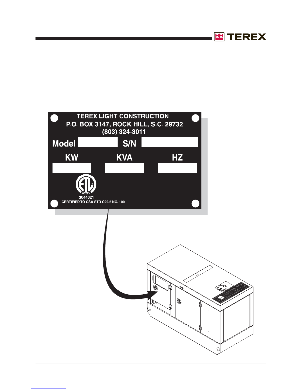
How to Read Your Serial Number
Serial Number Legend
The serial number plate on your T50 Super Quiet
Generator is located on the twist lock area of the
lower control panel.
Part No. 833009 T50 Super Quiet Generator
iii
Page 24
October 2006
REV A
This page intentionally left blank.
iv
T50 Super Quiet Generator Part No. 833009
Page 25
October 2006
Section 1 • Safety Rules
REV A
Safety Rules
Danger
Failure to obey the instructions and safety rules
in this manual and the appropriate Operator's
Manual on your machine will result in death or
serious injury.
Many of the hazards identified in the
operator’s manual are also safety hazards
when maintenance and repair procedures
are performed.
Do Not Perform Maintenance
Unless:
You are trained and qualified to perform
maintenance on this machine.
You read, understand and obey:
- manufacturer’s instructions and safety rules
- employer’s safety rules and worksite
regulations
- applicable governmental regulations
You have the appropriate tools, lifting
equipment and a suitable workshop.
Part No. 833009 T50 Super Quiet Generator
v
Page 26
Section 1 • Safety Rules
October 2006
REV ASAFETY RULES
Personal Safety
Any person working on or around a machine must
be aware of all known safety hazards. Personal
safety and the continued safe operation of the
machine should be your top priority.
Read each procedure thoroughly. This
manual and the decals on the machine,
use signal words to identify the following:
Safety alert symbol—used to alert
personnel to potential personal
injury hazards. Obey all safety
messages that follow this symbol
to avoid possible injury or death.
Red—used to indicate the
presence of an imminently
hazardous situation which, if not
avoided, will result in death or
serious injury.
Orange—used to indicate the
presence of a potentially
hazardous situation which, if not
avoided, could result in death or
serious injury.
Yellow with safety alert symbol—
used to indicate the presence of a
potentially hazardous situation
which, if not avoided, may cause
minor or moderate injury.
Yellow without safety alert
symbol—used to indicate the
presence of a potentially
hazardous situation which, if not
avoided, may result in property
damage.
Green—used to indicate operation
or maintenance information.
Be sure to wear protective eye wear and
other protective clothing if the situation
warrants it.
Be aware of potential crushing hazards
such as moving parts, free swinging or
unsecured components when lifting or
placing loads. Always wear approved steel-toed
shoes.
Workplace Safety
Be sure to keep sparks, flames and
lighted tobacco away from flammable and
combustible materials like battery gases
and engine fuels. Always have an approved fire
extinguisher within easy reach.
Be sure that all tools and working areas
are properly maintained and ready for
use. Keep work surfaces clean and free of
debris that could get into machine components and
cause damage.
Be sure that your workshop or work area
is properly ventilated and well lit.
Be sure any forklift, overhead crane or
other lifting or supporting device is fully
capable of supporting and stabilizing the
weight to be lifted. Use only chains or straps that
are in good condition and of ample capacity.
Be sure that fasteners intended for one
time use (i.e., cotter pins and self-locking
nuts) are not reused. These components
may fail if they are used a second time.
vi
Be sure to properly dispose of old oil or
other fluids. Use an approved container.
Please be environmentally safe .
T50 Super Quiet Generator Part No. 833009
Page 27
October 2006
REV A
Introduction
Important Information - Introduction ...................................................................
How to Read Your Serial Number .....................................................................
Parts Stocking List ............................................................................................
How to Order Parts ...........................................................................................
Service Parts Fax Order Form .........................................................................
Section 1 Safety Rules
General Safety Rules ........................................................................................
Section 2 Rev Specifications
A Specifications .............................................................................................. 2 - 1
A Newage Generator ...................................................................................... 2 - 2
A Torque Specifications .................................................................................. 2 - 3
Table of Contents
ii
iii
x
xi
xii
v
Section 3 Rev Scheduled Maintenance Procedures
Introduction .................................................................................................. 3 - 1
Pre-delivery Preparation Report................................................................... 3 - 2
A Maintenance Schedules
T50P Lubrication and Maintenance Service Intervals .................................. 3 - 3
T50J Lubrication and Maintenance Service Intervals .................................. 3 - 4
T50J and T50P Newage Generators Maintenance Schedule ...................... 3 - 5
Section 4 Rev Troubleshooting
Introduction .................................................................................................. 4 - 1
A Troubleshooting Guide ................................................................................. 4 - 3
Part No. 833009 T50 Super Quiet Generator
vii
Page 28
Section 5 Rev Schematics
A Introduction .................................................................................................. 5 - 1
A Electrical Schematic - Control Panel Wiring for
Murphy Cascade Controller ......................................................................... 5 - 2
A Electrical Schematic - Control Panel for Dynagen Controller ....................... 5 - 3
A Electrical Schematic - Distribution Panel Wiring ........................................... 5 - 4
A Electrical Schematic - Three Position Stack Switch Wiring .......................... 5 - 5
A Electrical Schematic - Overcurrent Relay Wiring ......................................... 5 - 6
A Electrical Schematic - Generator Wiring Breakdown .................................... 5 - 7
A Electrical Schematic - Standard Generator Wiring ....................................... 5 - 8
Section 6 Rev Decals
October 2006
REV ATABLE OF CONTENTS
A Figure 6-A Decals ................................................................................. 6 - 2
Section 7 Rev Base Components
A Figure 7-A Base Components ............................................................... 7 - 2
A Figure 7-B Base Components ............................................................... 7 - 4
Section 8 Rev Cabinet Components
A Figure 8-A Cabinet Components - Panels ............................................. 8 - 2
A Figure 8-B Cabinet Components - Doors .............................................. 8 - 4
Section 9 Rev Control Box Components
A Figure 9-A Control Panel - Upper .......................................................... 9 - 2
A Figure 9-B Control Panel - Lower .......................................................... 9 - 4
Section 10 Rev Control Box Components
A Figure 10-A Distribution Panel .............................................................. 10 - 2
A Figure 10-B Voltage Selector Switch ..................................................... 10 - 4
viii
T50 Super Quiet Generator Part No. 833009
Page 29
October 2006
REV A TABLE OF CONTENTS
Section 11 Rev Engine & Genset Components
A Figure 11-A Engine Genset Assembly - Perkins ................................... 11 - 2
A Figure 11-B Engine Genset Assembly - John Deere ............................. 11 - 4
A Figure 11-C Engine Muffler Assembly - John Deere & Perkins ............. 11 - 6
Section 12 Rev Trailer Components
A Figure 12-A Trailer Components ........................................................... 12 - 2
Section 13 Rev Options
A Figure 13-A Options LIst ....................................................................... 13 - 2
Part No. 833009 T50 Super Quiet Generator
ix
Page 30

October 2006
Parts Stocking List
Required Parts
The following parts are required to perform
maintenance procedures as outlined in the
TEREX T50 Parts and Service Manual.
Description Part No.
Perkins 1104C.44G2 Models
Oil Filter .............................................................. 741921
Air Filter .............................................. 866049 & 866048
Fuel Filter ........................................................... 741923
V-belt .................................................................. 866054
John Deere 4045DF270 Models
Oil Filter .............................................................. 741915
Air Filter .......................................................... 33100703
Fuel Filter ........................................................... 741916
V-belt .................................................................. 741942
REV A
x
T50 Super Quiet Generator Part No. 833009
Page 31
October 2006
REV A
Please be prepared with the following information
when ordering replacement parts for your TEREX
product:
Machine model number
Machine serial number
Terex part number
Part description and quantity
Purchase order number
"Ship to" address
Desired method of shipment
Name and telephone number of the
authorized TEREX Distributor in your area
Use the Service Parts Fax Order Form on the
next page and fax your order to our Parts
Department.
If you don't know the name of your authorized
distributor, or if your area is not currently serviced
by an authorized distributor, please call TEREX
Corporation.
How To Order Parts
TEREX North America
Telephone (803) 324-3011
Toll Free (800) 433-3026 in U.S.A. and Canada
Fax (803) 366-1101
Machine Information
Model
Serial Number
Date of Purchase
Authorized TEREX Distributor
Phone Number
Part No. 833009 T50 Super Quiet Generator
xi
Page 32
Service Parts fax Order Form
Please fill out completely
Date _________________________________ Account Number _______________________________
Your Name ______________________________ Your Fax Number _____________________________
_________________________________ Your Phone Number ____________________________
Bill To _________________________________ Ship To ___________________________________
_________________________________ ___________________________________
_________________________________ ___________________________________
_________________________________ ___________________________________
Purchase Order Number ____________________ Ship Via ___________________________________
Model(s) ______________________________________________________ Serial No.(s) _________________
FAX TO: (800) 633-5534 OR TOLL FREE: 800-433-3026
Optional Equipment __________________________________________________________________________
Part Number Description Quantity Price
remove this page and make copies
All backordered parts will be shipped when available via the same ship method as the original order
unless noted below:
o Ship complete order only - no backorders
o Ship all available parts and contact customer on disposition of backordered parts
o Other (please specify)
FOR TEREX USE ONLY
Order Number ______________ Origin Code ________________ Comments _________________________
Date Scheduled ____________ Ship Condition ______________ __________________________________
Order Total ________________ Terms Code ________________ __________________________________
remove this page and make copies
T50 Super Quiet Generator Part No. 833009
Page 33
November 2007
V
Section 2 • Specifications
REV B
Specifications
MODEL T50P T50J
POWER CAPABILITY-PRIME
kVA (kilovolt-amps) 50 50
kW 40 40
3 Phase Amp Ratings
208V 139 139
240V 120 120
480V 60 60
POWER CAPABILITY-STANDBY
kVA (kilovolt-amps) 54 54
kW (kilowatts) 43 43
3 Phase Amp Ratings 208V 150 150
240V 130 130
480V 65 65
OLTAGE
3 Phase 208, 220, 240, 416, 440, 480 Standard Standard
600 Volt Optional Optional
1 Phase 120, 127, 139, 240, 254, 277 Standard Standard
Max Motor Starting1 Hp 20 20
kW 15 15
SKVA 126 126
DIESEL ENGINE
Manufacturer PERKINS JOHN DEERE
Model 1104C-44G2 4045 DF270
Cylinder 4 4
Air Intake (aspiration) Natural Natural
Cooling System Std Rad Std Rad
Fuel Capacity (gal) 80 80
Run Time (75% load) 32 31
Fuel Consumption, Prime Power (gal per hr) 100% load 3.5 3.3
75% load 2.5 2.6
50% load 1.8 1.9
25% load 1.3 1.2
dBA 64 64
Controller Type Digital/Analog Analog
Start/Stop Controller Cascade Dynagen
12V Battery (CCA) 750 750
Part No. 833009 T50 Super Quiet Generator 2 - 1
Page 34
Section 2 • Specifications
October 2006
SPECIFICATIONS
MODEL T50P T50J
GENERATOR
Brushless, 4 pole, Synchronous, Single-bearing Standard Standard
1,800 rpm, Class H Insulation Generator Standard Standard
High wye, Low wy e, Zig-zag Voltage Selector Standard Standard
3 Phase Voltage: 208, 220, 240,416, 440, 480 Standard Standard
600 Volt Optional Optional
1Phase Voltage: 120, 127, 139, 240, 254, 277 Standard Standard
Convenience Receptacles: Standard Standard
2 - 20A, 120V GFCI Duplex Receptacles Standard Standard
2 - 50A Tempowers Standard Standard
AVR Voltage Regulation (+/- 1.5%) Standard Standard
Electronic (+/- 1/2%) Speed Control Governor Standard Standard
Murphy Cascade Start/Stop Controller Standard
Dynagen ES52 Start/Stop Controller Standard
TRAILER
HydraulicBrakes Standard Standard
Electric Brakes Optional Optional
Pintle Rng, 3 inch Standard Standard
Coupler Hitch, 2 inch Optional Optional
Coupler Hitch, 2 5/16 inch Optional Optional
REV A
SKID MOUNT
DIM (L x W x H - in) 88x40x53 88x40x53
Weight Dry (lbs) 3,069 3,069
Weight Full (lbs) 3,637 3,637
TRAILER MOUNT
Dim (L x W x H) 151x73x73 151x73x73
Weight Dry (lbs) 4,185 4,185
Weight Full (lbs) 4,745 4,745
1 Maximum motor size is based on 35% voltage dip at
480V AC 3 phase 60Hz with a code G motor
Standard Standard
Optional Optional
2 - 2 T50 Super Quiet Generator Part No. 833009
Page 35
October 2006
Section 2 • Specifications
REV A
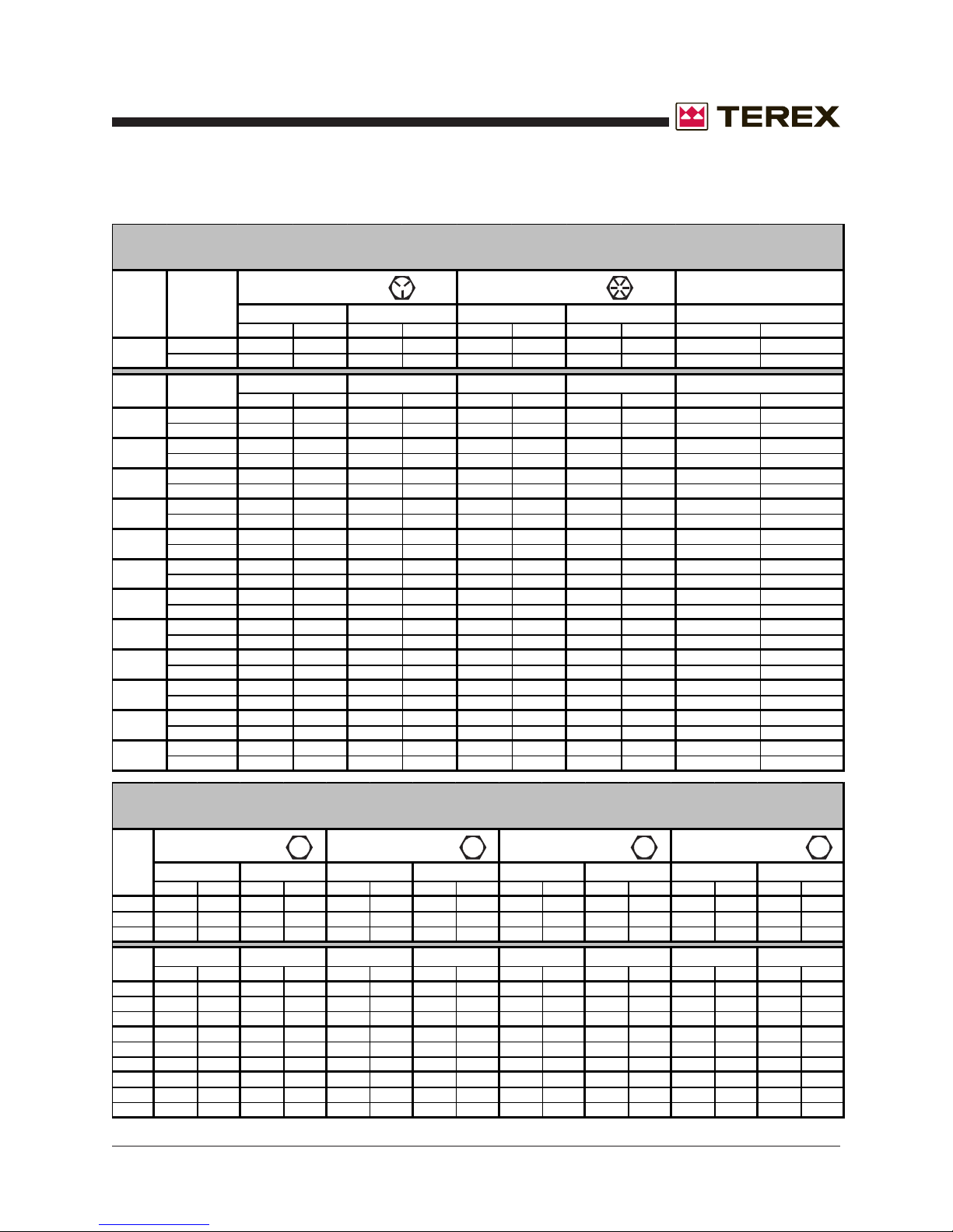
SIZE THREAD
1/4
5/16
3/8
7/16
1/2
9/16
5/8
3/4
7/8
1
1.125
1.25
1.5
20
28
18
24
16
24
14
20
13
20
12
18
11
18
10
16
14
12
12
12
12
SA E FASTENER TORQUE CHART
• T his chart i s t o be used as a g u ide on ly u n less noted elsewhere in t his manual •
Grade 5
DRYLUBED
in-lbs Nm in-lbs Nm in-lbs Nm in-lbs Nm in-lbs Nm
100 11.3 80 9 140 15.8 110 12.4 130 14.7
90 10.1 120 13.5 120 13.5 160 18 140 15.8
LUBED DRY LUBED DRY
ft-lbs Nm ft-lbs N m ft-lbs Nm ft-lbs N m ft-lbs Nm
13 17.6 17 23 18 24 25 33.9 21 28.4
14 19 19 25.7 20 27.1 27 36.6 24 32.5
23 31.2 31 42 33 44.7 44 59.6 38 51.5
26 35.2 35 47.4 37 50.1 49 66.4 43 58.3
37 50.1 49 66.4 50 67.8 70 94.7 61 82.7
41 55.5 55 74.5 60 81.3 80 108.4 68 92.1
57 77.3 75 101.6 80 108.4 110 149 93 126
64 86.7 85 115 90 122 120 162 105 142
80 108.4 110 149 120 162 150 203 130 176
90 122 120 162 130 176 170 230 140 189
110 149 150 203 160 217 210 284 180 244
130 176 170 230 180 244 240 325 200 271
200 271 270 366 280 379 380 515 320 433
220 298 300 406 310 420 420 569 350 474
9
8
7
7
6
320 433 430 583 450 610 610 827 510 691
350 474 470 637 500 678 670 908 560 759
480 650 640 867 680 922 910 1233 770 1044
530 718 710 962 750 1016 990 1342 840 1139
590 800 790 1071 970 1315 1290 1749 1090 1477
670 908 890 1206 1080 1464 1440 1952 1220 1654
840 1138 1120 1518 1360 1844 1820 2467 1530 2074
930 1260 1240 1681 1510 2047 2010 2725 1700 2304
1460 1979 1950 2643 2370 3213 3160 4284 2670 3620
1640 2223 2190 2969 2670 3620 3560 4826 3000 4067
Grade 8
A574 High Strength
SPECIFICATIONS
Black Oxide Bolts
LUBEDDRYLUBED
LUBED
METRIC FASTENER TORQUE CHART
• T his chart i s t o be used as a g uide o nly unless n o t ed elsewhere in t his manu al •
Size
(mm)
in-lbs Nm in- lbs Nm in- lbs Nm in- lbs Nm in- lbs Nm in- lbs Nm in- lbs Nm in- lbs Nm
16 1.8 21 2.4 41 4.63 54 6.18 58 6.63 78 8.84 68 7.75 91 10.3
5
19 3.05 36 4.07 69 7.87 93 10.5 100 11.3 132 15 116 13.2 155 17.6
6
45 5.12 60 6.83 116 13.2 155 17.6 167 18.9 223 25.2 1.95 22.1 260 29.4
7
ft-lbs N m ft-lbs Nm ft-lbs Nm ft-lbs N m ft-lbs Nm ft-lbs N m ft-lbs N m ft-lbs Nm
5.4 7.41 7.2 9.88 14 19.1 18.8 25.5 20.1 27.3 26.9 36.5 23.6 32 31.4 42.6
8
10.8 14.7 14.4 19.6 27.9 37.8 37.2 50.5 39.9 54.1 53.2 72.2 46.7 63.3 62.3 84.4
10
18.9 25.6 25.1 34.1 48.6 66 64.9 88 69.7 94.5 92.2 125 81 110 108 147
12
30.1 40.8 40 54.3 77.4 105 103 140 110 150 147 200 129 175 172 234
14
46.9 63.6 62.5 84.8 125 170 166 226 173 235 230 313 202 274 269 365
16
64.5 87.5 86.2 117 171 233 229 311 238 323 317 430 278 377 371 503
18
91 124 121 165 243 330 325 441 337 458 450 610 394 535 525 713
20
124 169 166 225 331 450 442 600 458 622 612 830 536 727 715 970
22
157 214 210 285 420 570 562 762 583 791 778 1055 682 925 909 1233
24
Part No. 833009 T50 Super Quiet Generator 2 - 3
DRYLUBED
Class 10.9Class 8.8
LUBEDDRYLUBED
LUBED DRY LUBED DRYLUBED DRY LUBED DRY
10.9 12.98.84.6
DRY
Class 12.9Class 4.6
LUBED DRY
Page 36
Section 2 • Specifications
October 2006
This page intentionally left blank.
2 - 4 T50 Super Quiet Generator Part No. SSQMT50J-P
Page 37
October 2006
Section 3 • Scheduled Maintenance Procedures
Scheduled Maintenance Procedures
About This Section
This section contains detailed procedures for each
scheduled maintenance inspection.
Each procedure includes a description, safety
warnings and step-by-step instructions.
Observe and Obey:
Maintenance inspections shall be completed by
a person trained and qualified on the
maintenance of this machine.
Scheduled maintenance inspections shall be
completed as specified using the supplied
Lubrication and Maintenance Service Interval
Charts
provided in this section
Failure to perform each procedure
as presented and scheduled could
result in death, serious injury or
substantial damage.
Immediately tag and remove from service a
damaged or malfunctioning machine.
Repair any machine damage or malfunction
before operating the machine.
Keep records on all inspections for three years.
Machines that have been out of service for a
period longer than 3 months must complete the
quarterly inspection.
Unless otherwise specified, perform each
maintenance procedure with the machine in the
following configuration:
· Machine parked on a firm, level surface
· Toggle switch in the "OFF" position
· Wheels chocked
.
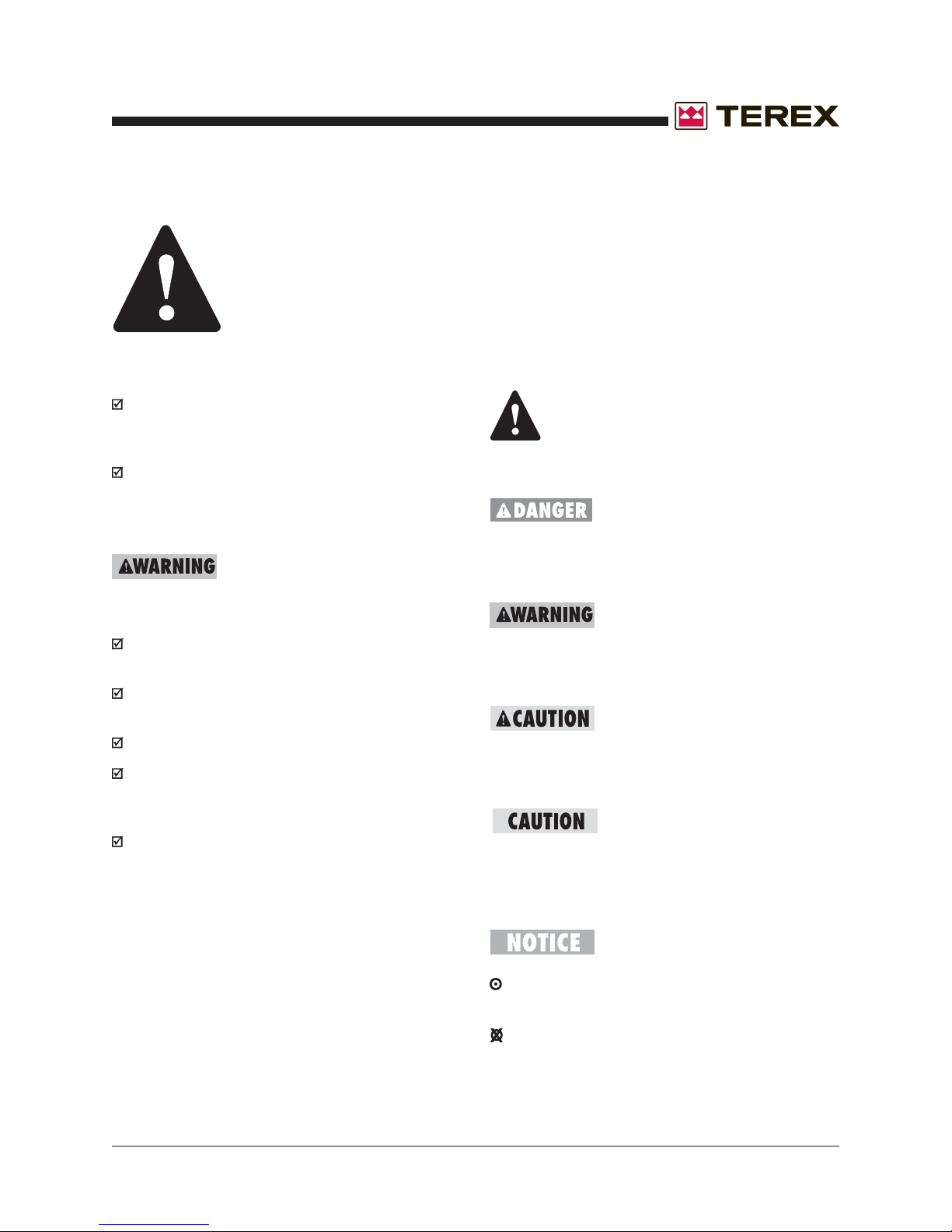
Symbols Legend
Safety alert symbol—used to alert
personnel to potential personal
injury hazards. Obey all safety
messages that follow this symbol
to avoid possible injury or death.
Red—used to indicate the
presence of an imminently
hazardous situation which, if not
avoided, will result in death or
serious injury.
Orange—used to indicate the
presence of a potentially
hazardous situation which, if not
avoided, could result in death or
serious injury.
Yellow with safety alert symbol—
used to indicate the presence of a
potentially hazardous situation
which, if not avoided, may cause
minor or moderate injury.
Yellow without safety alert
symbol—used to indicate the
presence of a potentially
hazardous situation which, if not
avoided, may result in property
damage.
Green—used to indicate operation
or maintenance information.
Part No. 833009 T50 Super Quiet Generator 3 - 1
Indicates that a specific result is expected after
performing a series of steps.
Indicates that an incorrect result has occurred
after performing a series of steps.
Page 38
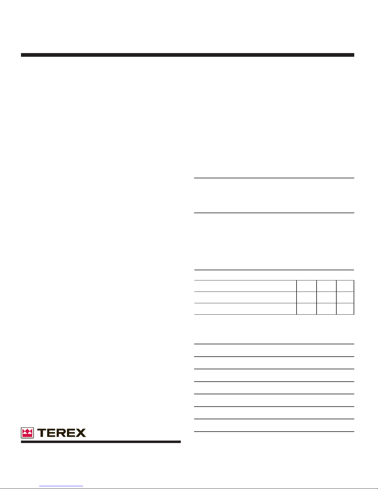
Pre-DeliverPre-Deliver
Pre-Deliver
Pre-DeliverPre-Deliver
y Preparationy Preparation
y Preparation
y Preparationy Preparation
Fundamentals
It is the responsibility of the dealer to perform the
Pre-delivery Preparation.
The Pre-delivery Preparation is performed prior to each
delivery. The inspection is designed to discover if anything
is apparently wrong with a machine before it is put into
service.
A damaged or modified machine must never be used. If
damage or any variation from factory delivered condition is
discovered, the machine must be tagged and removed
from service.
Repairs to the machine may only be made by a qualified
service technician, according to the manufacturer's
specifications.
Scheduled maintenance inspections shall be performed by
qualified service technicians, according to the
manufacturer's specifications and the requirements listed
in the responsibilities manual.
Instructions
Use the operator’s manual on your machine.
The Pre-delivery Preparation consists of completing the
Pre-operation Inspection, the Maintenance items and the
Function Tests.
Use this form to record the results. Place a check in the
appropriate box after each part is completed. Follow the
instructions in the operator’s manual.
If any inspection receives an N, remove the machine from
service, repair and re-inspect it. After repair, place a check
in the R box.
Legend
Y = yes, completed
N = no, unable to complete
R = repaired
Comments
TEREX North America
P.O. BOX 3147
Rock Hill, SC 29732 USA
Toll Free (800) 433-3026 in U.S.A. and Canada
Copyright © 2006 by TEREX Corporation. TEREX® is a registered trademark of TEREX
Corporation.
Rev B
Pre-Delivery Preparation Y N R
Pre-operation inspection completed
Maintenance items completed
Function tests completed
Model
Serial number
Date
Machine owner
Inspected by (print)
Inspector signature
Inspector title
Inspector company
Page 39
October 2006
Section 3 • Scheduled Maintenance Procedures
REV A
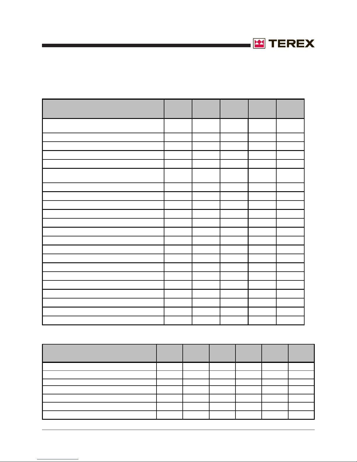
T50P LUBRICATION AND MAINTENANCE SERVICE INTERVALS
ITEM
Inspect, adjust or replace alternator or fan belt
Check cooling system coolant level
Check driven equipment
Inspect engine air cleaner service indicator
Check engine oil level
Drain fuel system primary filter/water
separator
Walk around inspection
Drain tank water and sediment
Check battery electrolyte level
Clean/replace engine air cleaner element
Inspect/clean engine ground
Change engine oil and filter
Replace water separator element
Replace fuel system secondary filter
Inspect/replace hoses and clamps
Inspect/adjust engine valve lash
Inspect aftercooler core
Inspect alternator
Inspect engine mounts
Inspect starting motor
Inspect turbocharger
Inspect water pump
Maintenance Schedules
DAILY
•
•
•
•
•
•
•
50 Hrs or
Wkly
•
500 Hrs or
12 Mths
•
•
•
•
•
•
•
1000 Hrs 2000 Hrs
•
•
•
•
•
•
•
ITEM
Change cooling system coolant
Test/change fuel injector
Change cooling system coolant
(commer cial heavy duty)
Clean/test aftercooler core
Add cooling system coolant extender (ELC)
Change cooling system coolant (ELC)
Part No. 833009 T50 Super Quiet Generator 3 - 3
2 Yrs 3000 Hr s
•
•
3000 Hrs or
2 Yrs
•
4000 Hrs
•
6000 Hrs or
3 Yrs
•
12000 Hrs
or 6 Yrs
•
Page 40
Section 3 • Scheduled Maintenance Procedures
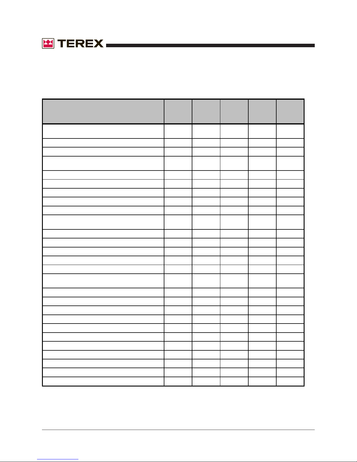
MAINTENANCE SCHEDULES CONTINUED
T50J LUBRICATION AND MAINTENANCE SERVICE INTERVALS
October 2006
REV A
ITEM
Operate engine at rated speed and 50%-70%
load a minium of 30 minutes
Check engine oil and coolant level
Check fuel filter/water separator bowl
Check air cleaner dust unloader valve and
indicator
Perform visual walk around inspection
Change engine oil and replace filter
Check engine mounts
Service battery
Clean crankcase vent tube
Check air intake hoses, connections and
system
Replace single or dual fuel filter elements
Check belt tensioner and belt wear
Check engine speeds
Check engine electrical ground connection
Check cooling system
Coolant solution analysis-add SCAs as
required
Pressure test cooling system
Check variable speed (droop) (gensets)
Flush cooling system
Test thermostats
Check and adjust engine valve clearance
Add coolant
Replace air cleaner elements
Replace poly-vee belt
Checkfuses
Check air compressor (if equipped)
Bleed fuel system
Every 2
Weeks
•
•
•
•
•
250 Hrs or
12 Mths
•
•
•
500 Hrs or
12 Mths
•
•
•
•
•
•
•
•
•
2000 Hrs or
12 Mths
•
•
•
•
As Req.
•
•
•
•
•
•
3 - 4 T50 Super Quiet Generator Part No. 833009
Page 41
October 2006
Section 3 • Scheduled Maintenance Procedures
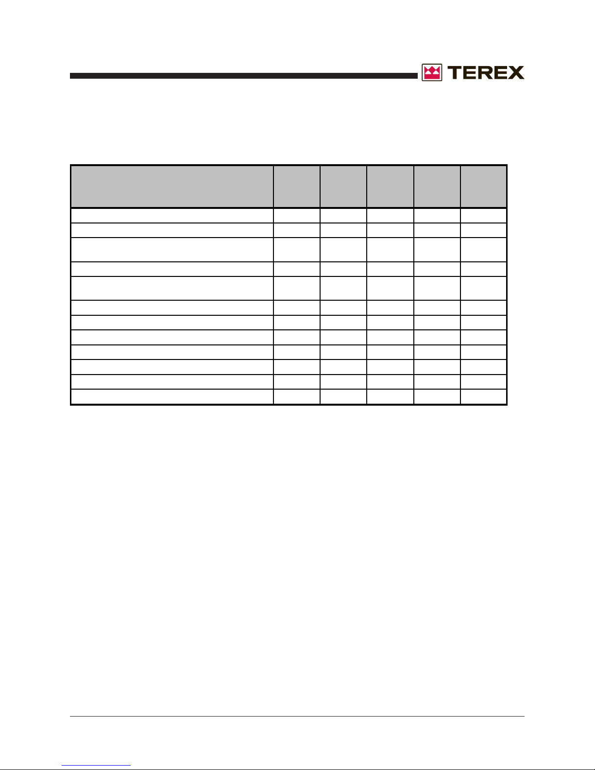
MAINTENANCE SCHEDULES CONTINUED
T50J AND T50P NEWAGE GENERATORS MAINTENANCE SCHEDULE
ITEM
Visual inspection
Visual inspection plus running audible check
Measure stator winding insulation resistance
and record
Monitor bearing/s condition
Remove terminal box lid and check
connections
Re-grease bearings
Measure vibration levels
Replace bearing/s
Replace NDE o-ring
Inspect bearing housings
Inspect winding conditions
Inspect rotating diode assembly
DAILY
•
250 Hours
or 3
Months
•
1500 Hours
or 12
Months
•
•
•
4500 Hours
or 3 Years
•
15000
Hours or 19
Years
•
•
•
•
•
•
*Refer to the manufacturers manuals for detailed maintence intervals and instructions. If the
information in the manufacturer's manual differs from that in this manual the manufacturer's manual
should take precedence.
Part No. 833009 T50 Super Quiet Generator 3 - 5
Page 42
Section 3 • Scheduled Maintenance Procedures
October 2006
REV A
This page intentionally left blank.
3 - 6 T50 Super Quiet Generator Part No. 833009
Page 43
Section 4 • TroubleshootingOctober 2006
Observe and Obey:
Troubleshooting and repair procedures shall be
completed by a person trained and qualified on
the repair of this machine.
Immediately tag and remove from service a
damaged or malfunctioning machine.
Repair any machine damage or malfunction
before operating the machine.
Unless otherwise specified, perform each
repair procedure with the machine in the
following configuration:
· Machine parked on a firm, level surface
· Wheels chocked
Troubleshooting
Before Troubleshooting:
Read, understand and obey the safety rules
and operating instructions in the appropriate
operator's manual on your machine.
Be sure that all necessary tools and test
equipment are available and ready for use.
Be aware of the following hazards and follow
generally accepted safe workshop practices.
Electrocution hazard. Exposure to
electrically charged circuits could
result in death or serious injury.
Remove all rings, watches and
other jewelry.
Electrocution hazard. Attempting
to sevice the machine before the
capacitors are fully discharged will
result in death or serious injury.
High voltage. Exposure to
electrical wires or electrical current
will result in death or serious
injury. Remove all rings, watches
and other jewelry. Turn off all
power when not needed for
testing. Use extreme caution when
working with high voltage electrical
components.
Part No. 833009 T50 Super Quiet Generator 4 - 1
Burn hazard. Contact with hot
engine components may cause
severe burns. Use caution when
working around a hot engine.
Page 44
Section 4 • Troubleshooting October 2006
Troubleshooting Guide
The engine/generator set is tested and set at the factory for proper operation in the field. These units
should never require additional adjustments in the field. If needed, adjustments should only be made by a
qualified service technician, otherwise the manufacturer’s warranty may become void.
FAULT POSSIBLE CAUSE SOLUTION
No generator output voltage Circuit breaker tripped Reset circuit breaker
Voltage regulator Check voltage regulator wiring
Defective voltage regulator Replace voltage regulator
Defective Selector Switch By pass by hardwiring generator
Defective generator Refer to generator manual
Low generator output voltage Voltage adjustment Adjust voltage potentiometer
set too low
Defective potentiometer By pass or replace
Low engine speed Call TEREX Service
Loose wire on voltage Check wiring
selector switch
Fluctuating or surging Check engine fuel, oil,
engine speed and air filters
Loose wire on voltage Check wiring
regulator sensing circuit
Defective voltage regulator Replace voltage regulator
High generator Voltage adjustment Adjust potentiometer
output voltage potentiometer
High engine speed Call TEREX Service
4 - 2 T50 Super Quiet Generator Part No. 833009
Page 45
Section 4 • TroubleshootingOctober 2006
FAULT POSSIBLE CAUSE SOLUTION
High generator Defective automatic Replace voltage
output voltage voltage regulator regulator
Loose wire on voltage Check wiring
adjustment potentiometer
Fluctuating generator An “ON/OFF” type Redistribute load if
output voltage load may be the cause possible
Fluctuating or surging Check engine fuel, oil,
engine speed and air filters
Loose wiring in generator Check connections
Automatic voltage regulator Call TEREX Service
stability setting may be
wrong
TROUBLESHOOTING
Loose wire on the automatic Check wiring
voltage regulator sensing lead
Low engine speed Engine speed adjustment Call TEREX Service
has slipped
Clogged fuel system Check for air leaks, clogged fuel
filter, kinked fuel line, or
clogged fuel pick-up tube
Blocked air intake Check air filter
Blocked exhaust system Check engine exhaust
system, remove
obstructions
Contaminated fuel Check fuel/water separator and
fuel tank for contamination.
Replace fuel if needed
Defective governor on engine Call TEREX Service
Part No. 833009 T50 Super Quiet Generator 4 - 3
Page 46
Section 4 • Troubleshooting October 2006
TROUBLESHOOTING
FAULT POSSIBLE CAUSE SOLUTION
Low Speed Defective injectors on engine Have injectors checked by a
qualified technician
“Surging” engine speed Check engine fuel, oil,
and air filters
Engine turns over (cranks), Unit out of fuel Check fuel level in tank, fill as
but won’t run needed
Loose or broken wire in Check wiring to verify 12V DC
control circuit fuel injection is being supplied to the pump
pump solenoid solenoid
Defective solenoid Replace solenoid
Magnetic Pick-up Adjust for 2.5-3.0 VAC
Clogged fuel system Check fuel system
Air in fuel system “Bleed” fuel system
Defective fuel pump Check and replace if defective
Clogged air intake Check air cleaner
Clogged exhaust Check exhaust system
Contaminated fuel Check fuel/water separator and
tank for contamination
Defective injectors Have injection system checked
by a trained technician
Lost engine compression Have compression checked by
a trained technician
Engine won’t crank Loose battery cable Check cables and battery
or discharged battery electrolyte level. Recharge
as necessary
4 - 4 T50 Super Quiet Generator Part No. 833009
Page 47
Section 4 • TroubleshootingOctober 2006
TROUBLESHOOTING
FAULT POSSIBLE CAUSE SOLUTION
Engine won’t crank Engine “ON/OFF” switch Check switch position
set in “OFF” position
Blown fuse in DC Replace with 25 Amp.
control circuit SLO-BLO TYPE
fuse if needed.
E-Stop Check to see if engaged
Defective starter Replace solenoid
solenoid
Defective starter Replace starter
Oil Pressure or Hi temp Check or call TEREX Service
switch defective
Seized engine Have engine checked by a
qualified technician
Engine runs, but loses Unit is overloaded Reduce load
speed
Improper connection Check or Call TEREX Service
Engine runs, but loses Clogged fuel system Check fuel system
power under load air in fuel lines
Blocked air intake Check air cleaner
Blocked exhaust Check exhaust system
Contaminated fuel Check fuel/water separator and
fuel tank for contamination
Faulty governor, defective Have unit checked by a
injectors, or defective fuel trained service technician
pump for all of these items
Engine shuts down Oil Pressure Switch Not opening
automatically and
TROUBLE LIGHT on Improper coolant Use a 50/50 on
CONTROL PANEL or water mixture mix of water and
is illuminated anti-freeze only
Part No. 833009 T50 Super Quiet Generator 4 - 5
Page 48
Section 4 • Troubleshooting October 2006
TROUBLESHOOTING
FAULT POSSIBLE CAUSE SOLUTION
Engine shuts down Overloaded engine Reduce load
automatically and
TROUBLE LIGHT on Broken fan belt Inspect fan belt and replace as
CONTROL PANEL needed
is illuminated
Defective thermostat or Inspect thermostat
thermocouple switch switch
Defective water pump Inspect water pump and replace
if needed
Blocked cooling air inlet Inspect and remove any
or exhaust obstructions
Defective or grounded Inspect switch and repair or
temperature switch replace
Defective injectors or Have the engine inspected by a
injector pump trained service technician
Low crankcase oil level Check oil level and refill as
required
Defective oil pump Have the engine inspected by
a trained service technician
Defective or grounded oil Inspect switch and repair or
pressure switch replace
IF YOU FEEL AN ELECTRIC SHOCK AT ANY TIME WHILE OPERATING THIS UNIT, SHUT IT DOWN
IMMEDIATELY! HAVE THE UNIT INSPECTED BY A TRAINED ELECTRICIAN.
THIS ENGINE/GENERATOR SET IS FACTORY INSTALLED, TESTED, AND SET FOR FIELD
OPERATION. ANY DAMAGE TO THE ENGINE OR GENERATOR UNITS OCCURRING AFTER
ADJUSTMENTS ARE MADE IN THE FIELD BY UNAUTHORIZED PERSONNEL WILL NOT BE
COVERED BY YOUR MANUFACTURER’S WARRANTY AND WILL ALSO VOID THE
MANUFACTURER’S WARRANTY ON THIS PARTICULAR UNIT. IF YOU CAN NOT REACH YOUR
LOCAL DEALER, CONTACT THE FACTORY SERVICE MANAGER TOLL FREE AT 1-800-433-3026.
4 - 6 T50 Super Quiet Generator Part No. 833009
Page 49
Section 4 • TroubleshootingOctober 2006
TROUBLESHOOTING
Electrical Troubleshooting
5 Components that cause voltage
related problems
Potentiometer
Connects to voltage regulator. Bypass potentiometer by unplugging from voltage regulator and
installing jumper on 2 male spades on regulator.
Voltage Regulator
(Located inside the upper control panel behind the
gauges.)
Measure DC voltage at F1 & F2. Normal voltage is
10 to 12 V DC. Remove 2 wires marked (F1,
X)(F2, X X) from voltage regulator. Connect wire
marked F1 to positive and F2 to negative of a 12
volt battery. Start unit and measure voltage. If unit
produces close to maximum output, replace
Automatic Voltage Regulator.
Voltage Selector Switch
The correct way to test is to disconnect from
generator and hard wire the generator into one
configuration. This will eliminate the switch from
the circuit and verify that the generator is functioning properly. All contacts should be checked
following the proper schematic with the switch
disconnected from the generator set. Actual loads
can cause failures in contacts that cannot be
duplicated using a meter.
Generator
Test resistance of field, stator and exciter windings. Contact TEREX for procedures or repair
facility recommended by generator manufacturer.
Procedure for testing
generator with no output
THIS EQUIPMENT USES HIGH VOLTAGE
CIRCUITS CAPABLE OF CAUSING SERIOUS
INJURY OR DEATH! EXCERCISE EXTREME
CAUTION AROUND ANY ELECTRICAL
COMPONENT WHEN OPERATING THIS UNIT.
IT IS ESSENTIAL THAT ALL TEST INSTRUMENTS ARE REGULARLY CHECKED FOR
SAFETY, AND ANY CONNECTION LEADS,
PROBES, OR CLIPS, ARE CHECKED TO
ENSURE THAT THEY ARE SUITABLE FOR
THE VOLTAGE LEVELS BEING TESTED.
NEVER ATTEMPT TO TEST A "LIVE" GENERATOR UNLESS THERE IS ANOTHER COMPETENT PERSON PRESENT WHO CAN SWITCH
OFF THE POWER SUPPLY OR SHUT DOWN
THE ENGINE IN AN EMERGENCY.
NEVER EXPOSE "LIVE" CONNECTIONS UNLESS YOU HAVE CREATED A SAFE WORKING
AREA AROUND YOU. MAKE SURE YOU HAVE
MADE ALL OTHER PERSONS IN THE IMMEDIATE AREA FULLY AWARE OF WHAT YOU ARE
DOING.
Overcurrent Relay
This device causes the 3-phase breaker to trip
that supplies AC power to the distribution lugs if
uneven or excessive current is measured at the
distribution lugs. It is also connected to the 3phase door switch and will automatically trip the 3phase breaker when the door is open and prevents the breaker from being reset while it is open.
Part No. 833009 T50 Super Quiet Generator 4 - 7
• When a new generator is not producing voltage,
the testing or wiring personnel should first verify
that the unit is wired correctly! The stack switch
and generator leads should all be checked as
well as the breaker and sensing leads. If the
unit was not wired correctly and you flashed the
generator, you could burn up the unit. (Do not
forget to check the sensing leads!).
Page 50
TROUBLESHOOTING
Section 4 • Troubleshooting October 2006
Procedure for testing
generator with no output
(cont.)
• After performing the initial checks above,
remove the field wires from the voltage
regulator (F1 or X is positive and F2 or XX is
negative). Connect the battery + to the F1 or X
wire and battery - to the F2 or XX wire. Start the
engine and check for the rated voltage.
Hooking this up incorrectly will reverse
polarity and could damage the voltage
regulator and /or generator end. This check
should correct any voltage problems. If your
voltage does not come up to the rated voltage,
this indicates an internal problem with the
generator end. The output should be close to
proper voltage. Also, if the unit comes up to
voltage, check for even reading across the lines
if they are not this would mean you probably
have a problem with the wiring of the switch or
generator. If the generator voltage reads
correctly you know there is not a problem with
the generator end. Your problem is more than
likely with the voltage regulator. In this case,
you should contact the TEREX service
department.
• If the voltage is uneven between the legs when
you apply 12 volts to the field wires you need to
recheck your wiring connections. (If you can
not find the problem hard wire the
generator!) After you have the field wire
connected start the unit again and check your
output voltage. It may still be necessary to flash
the fields to restore residual voltage. This needs
to be done with the unit off and the field wires
removed. (Do not flash the regulator, flash
the field wires)
INSTALLATION AND ANY WORK PERFORMED
ON THIS UNIT SHOULD BE DONE ONLY BY A
QUALIFIED ELECTRICIAN.
Procedure for changing the
magnetic pick-up sensor
THIS EQUIPMENT USES HIGH VOLTAGE CIRCUITS CAPABLE OF CAUSING SERIOUS INJURY OR DEATH! EXCERCISE EXTREME CAUTION AROUND ANY ELECTRICAL COMPONENT WHEN OPERATING THIS UNIT.
INSTALLATION AND ANY WORK PERFORMED
ON THIS UNIT SHOULD BE DONE ONLY BY A
QUALIFIED ELECTRICIAN.
• Make sure generator is turned off and e-stop is
engaged before opening control panel.
• Locate the two wires going to the speed
controller mounted on the inside of the control
pan marked MPU + and MPU -.
• Both wires are isolated in their own shielded
cable.
• Once the wires are loose, pull them through the
back of the control box until they are completely
free from all ty-wraps and wire harnesses.
• Unscrew and remove the old sensor.
• Align the flywheel tooth to the center of the
sensor hole.
• As with any electrical device use extreme
caution when working around a running
generator it could cost you your life. Observe
proper polarity when working with the regulator
so you don’t break something that is not broken
to begin with, and if you are ever in doubt, ask.
4 - 8 T50 Super Quiet Generator Part No. 833009
• Install new sensor until it bottoms out on
flywheel tooth and then back it off ¼ turn.
• To insure proper installation, the sensor must
Page 51
Section 4 • TroubleshootingOctober 2006
TROUBLESHOOTING
Procedure for changing the
magnetic pick-up sensor
(cont.)
be checked with a voltage meter. With the
engine in a starting sequence check for 2.5 to 3
VAC between the red and black wire. Adjust the
sensor in or out to obtain the correct voltage.
• Once the voltage is correct, reinstall the
shielded cable through the control box opening
and reattach the wire leads to the speed
controller. Also, secure the new cable through
the housing with ty-wraps where needed.
If any further adjustment is needed to the voltage
of the generator please call Terex at 1-800-4333026 for assistance.
Procedure for changing the
voltage potentiometer
• Once the wires are loose, go to the front of the
control panel and loosen the lock nut holding
the potentiometer.
• Put the new potentiometer in its place and
retighten lock nut.
• Reattach new wires to the same wires and in
the same configuration as the ones that were
cut loose in step 3.
• After completing the installation of the new
potentiometer go back and check all
connections to make sure everything is tight
and that no connections are loose, this includes
all other wiring on the back of the control panel
and on the inside of the control box.
• You should now be able to restart the generator
and check for proper operation.
THIS EQUIPMENT USES HIGH VOLTAGE
CIRCUITS CAPABLE OF CAUSING SERIOUS
INJURY OR DEATH! EXCERCISE EXTREME
CAUTION AROUND ANY ELECTRICAL
COMPONENT WHEN OPERATING THIS UNIT.
INSTALLATION AND ANY WORK PERFORMED
ON THIS UNIT SHOULD BE DONE ONLY BY A
QUALIFIED ELECTRICIAN.
• Make sure generator is turned off and e-stop is
engaged before opening control panel.
• Locate the two wires going to the back of the
potentiometer. Both wires will be white with a
red stripe.
• Both wires have been spliced into harness
wires and should be cut so that the splice is
taken out. It is better to have as few splices as
possible and you will be replacing the splice
you cut out.
If any further adjustment is needed to the voltage
of the generator please call TEREX at 1-800-4333026 for assistance.
Part No. 833009 T50 Super Quiet Generator 4 - 9
Page 52
Section 4 • Troubleshooting October 2006
This page intentionally left blank.
4 - 10 T50 Super Quiet Generator Part No. 833009
Page 53
October 2006
Section 5 • Schematics
REV A
Observe and Obey:
Troubleshooting and repair procedures shall be
completed by a person trained and qualified on
the repair of this machine.
Immediately tag and remove from service a
damaged or malfunctioning machine.
Repair any machine damage or malfunction
before operating the machine.
Before Troubleshooting:
Read, understand and obey the safety rules
and operating instructions in the appropriate
operator's manual on your machine.
Be sure that all necessary tools and test
equipment are available and ready for use.
Schematics
About This Section
There are two groups of schematics in this section.
An illustration legend precedes each group of
drawings.
Electrical Schematics
Electrocution hazard. Contact with
electrically charged circuits could
result in death or serious injury.
Remove all rings, watches and
other jewelry.
General Repair Process
Malfunction
discovered
Return to
service
still exists
problem
solved
Identify
symptoms
problem
Inspect
and test
Troubleshoot
Perform
repair
Part No. 833009 T50 Super Quiet Generator 5 - 1
Page 54
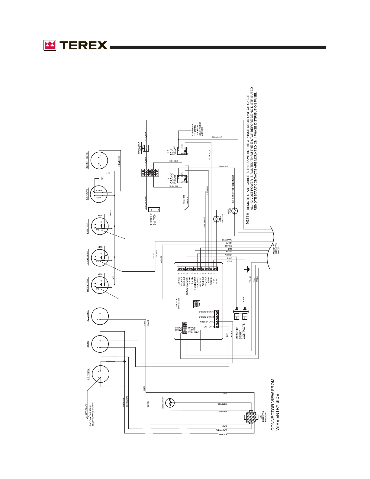
Control Panel Wiring
for Murphy Cascade Controller
Drawing #ES1000001 (Standard)
Section 5 • Schematics
October 2006
REV A
5 - 2 T50 Super Quiet Generator Part No. 833009
Page 55
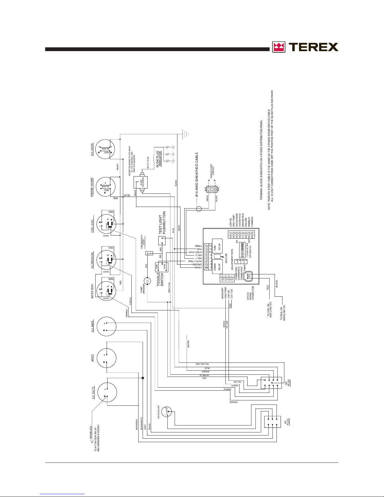
October 2006
REV A
Section 5 • Schematics
Control Panel Wiring
for Dynagen Controller
Drawing #EU0007
Part No. 833009 T50 Super Quiet Generator 5 - 3
Page 56
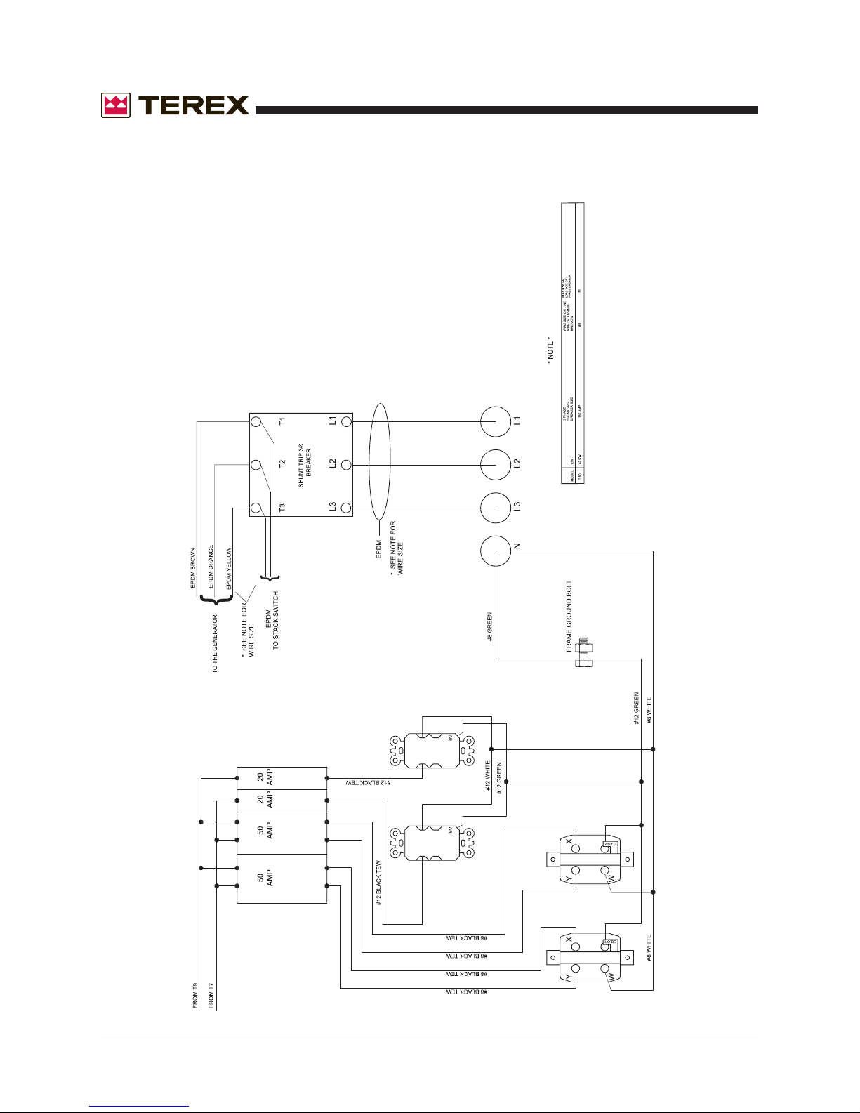
Distribution Panel Wiring
for "D" Series Single Phase Control
Drawing #ES1000003
Section 5 • Schematics
October 2006
REV A
5 - 4 T50 Super Quiet Generator Part No. 833009
Page 57
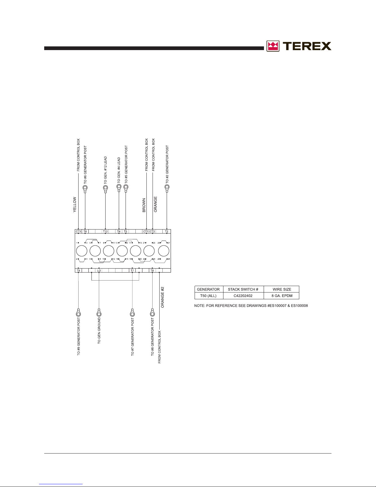
October 2006
REV A
Section 5 • Schematics
Three Position Stack Switch Wiring
Drawing #ES1000005
Part No. 833009 T50 Super Quiet Generator 5 - 5
Page 58
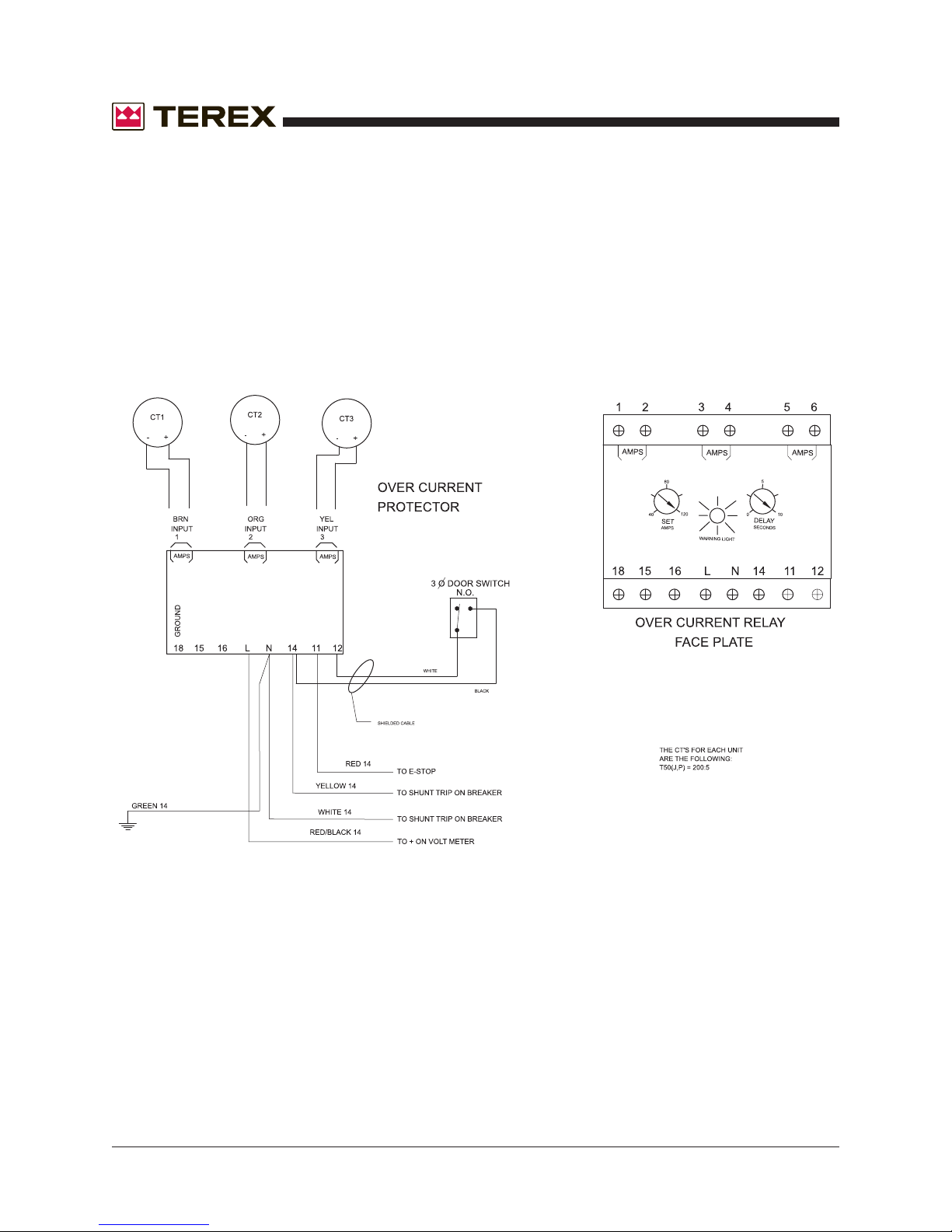
Overcurrent Relay Wiring
Drawing #ES1000006
Section 5 • Schematics
October 2006
REV A
5 - 6 T50 Super Quiet Generator Part No. 833009
Page 59
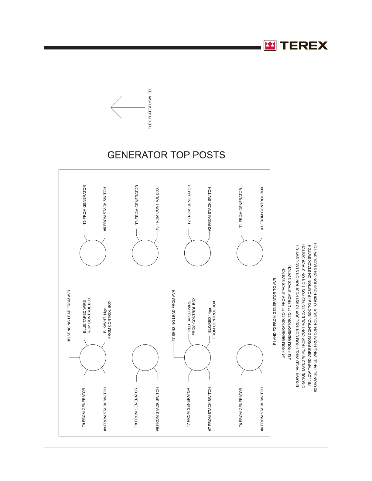
October 2006
REV A
Section 5 • Schematics
Generator Wiring Breakdown
Drawing #ES1000007
Part No. 833009 T50 Super Quiet Generator 5 - 7
Page 60
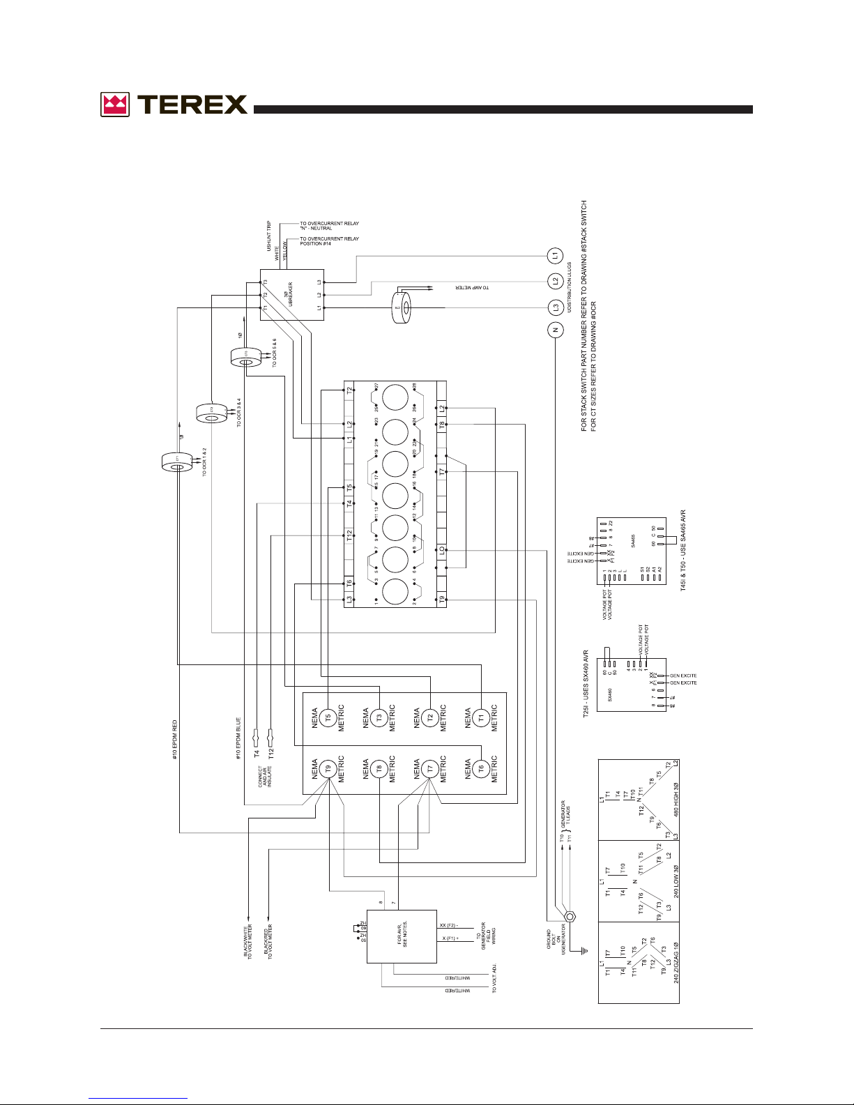
Standard Generator Wiring
for "D" Series
Drawing #ES1000008
Section 5 • Schematics
October 2006
REV A
5 - 8 T50 Super Quiet Generator Part No. 833009
Page 61

October 2006
Section 6 • Decals
Section Six
Decals
Part No. 833009 T50 Super Quiet Generator 6 - 1
Page 62
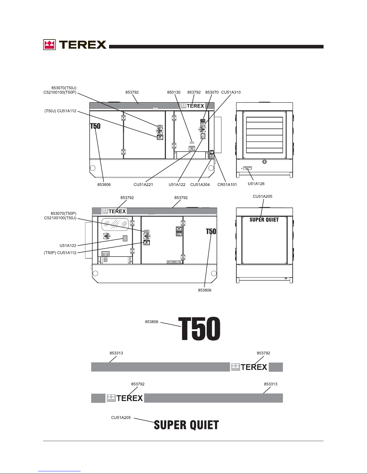
Section 6 • Decals
October 2006
Figure 6-A
Decals
REV A
6 - 2 T50 Super Quiet Generator Part No. 833009
Page 63
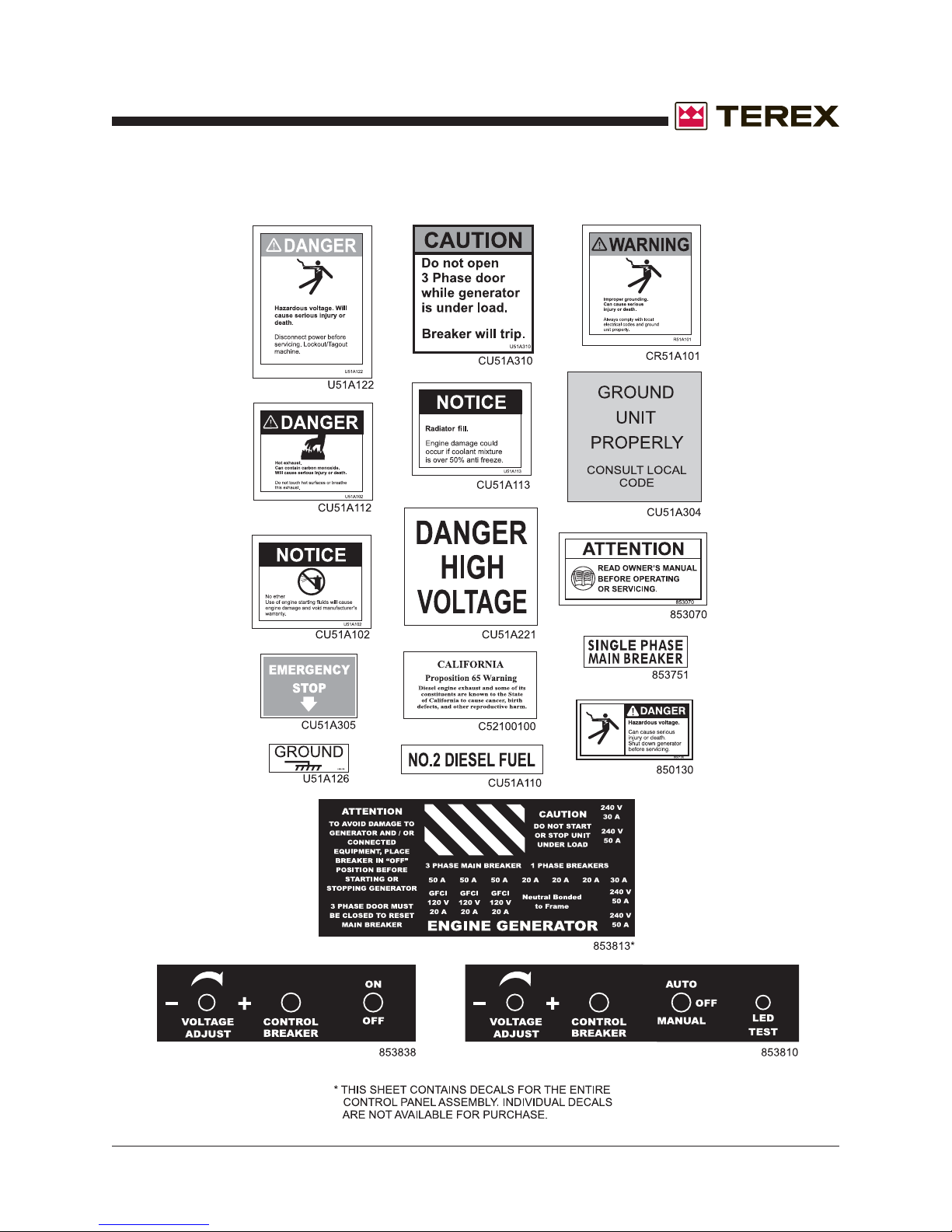
October 2006
Section 6 • Decals
REV A
FIGURE 6-A
Part No. 833009 T50 Super Quiet Generator 6 - 3
Page 64
Section 6 • Decals
October 2006
This page intentionally left blank.
6 - 4 T50 Super Quiet Generator Part No. 833009
Page 65

October 2006
Section 7 • Base Components
Section Seven
Base
Components
Part No. 833009 T50 Super Quiet Generator 7 - 1
Page 66
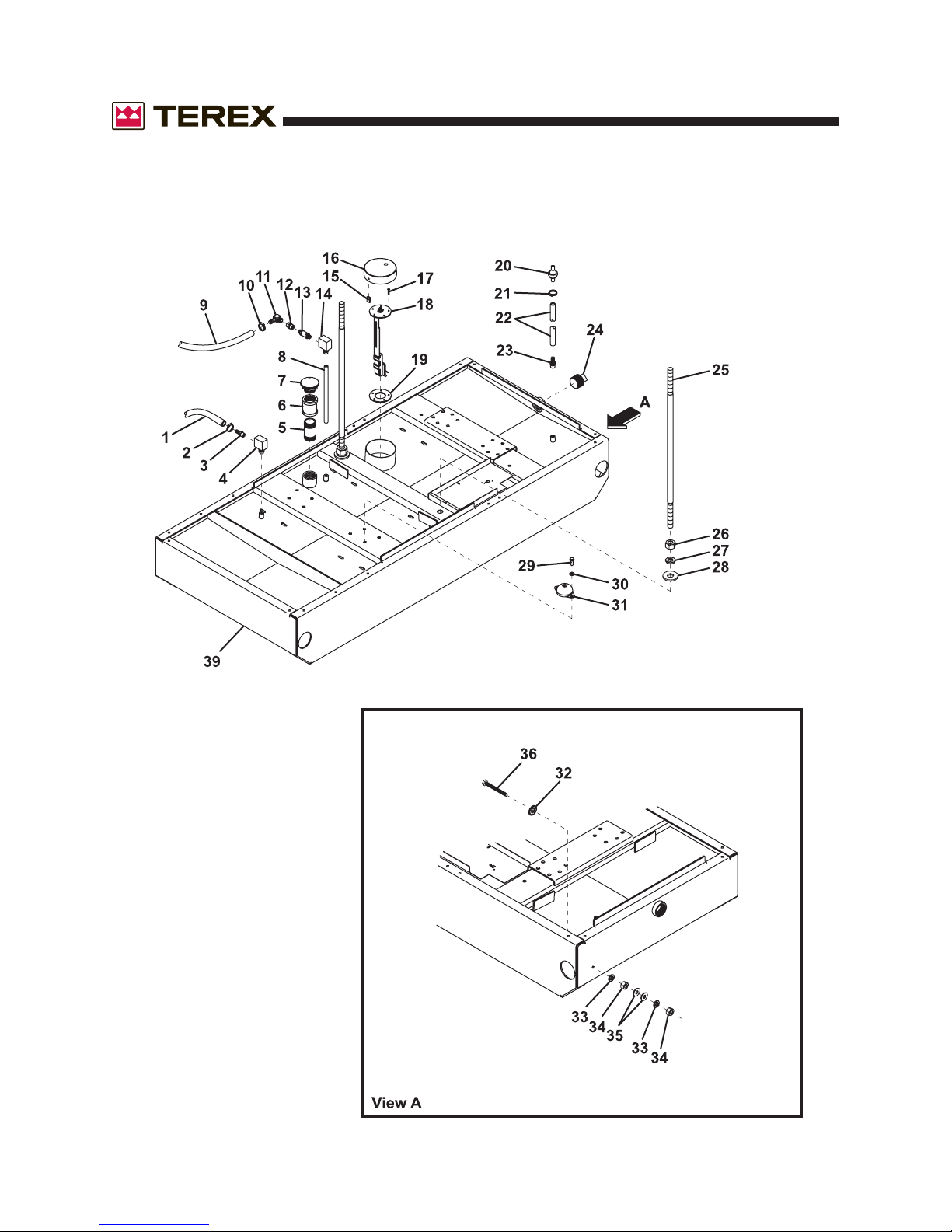
Section 7 • Base Components
October 2006
Figure 7-A
Base Components
REV A
7 - 2 T50 Super Quiet Generator Part No. 833009
Page 67
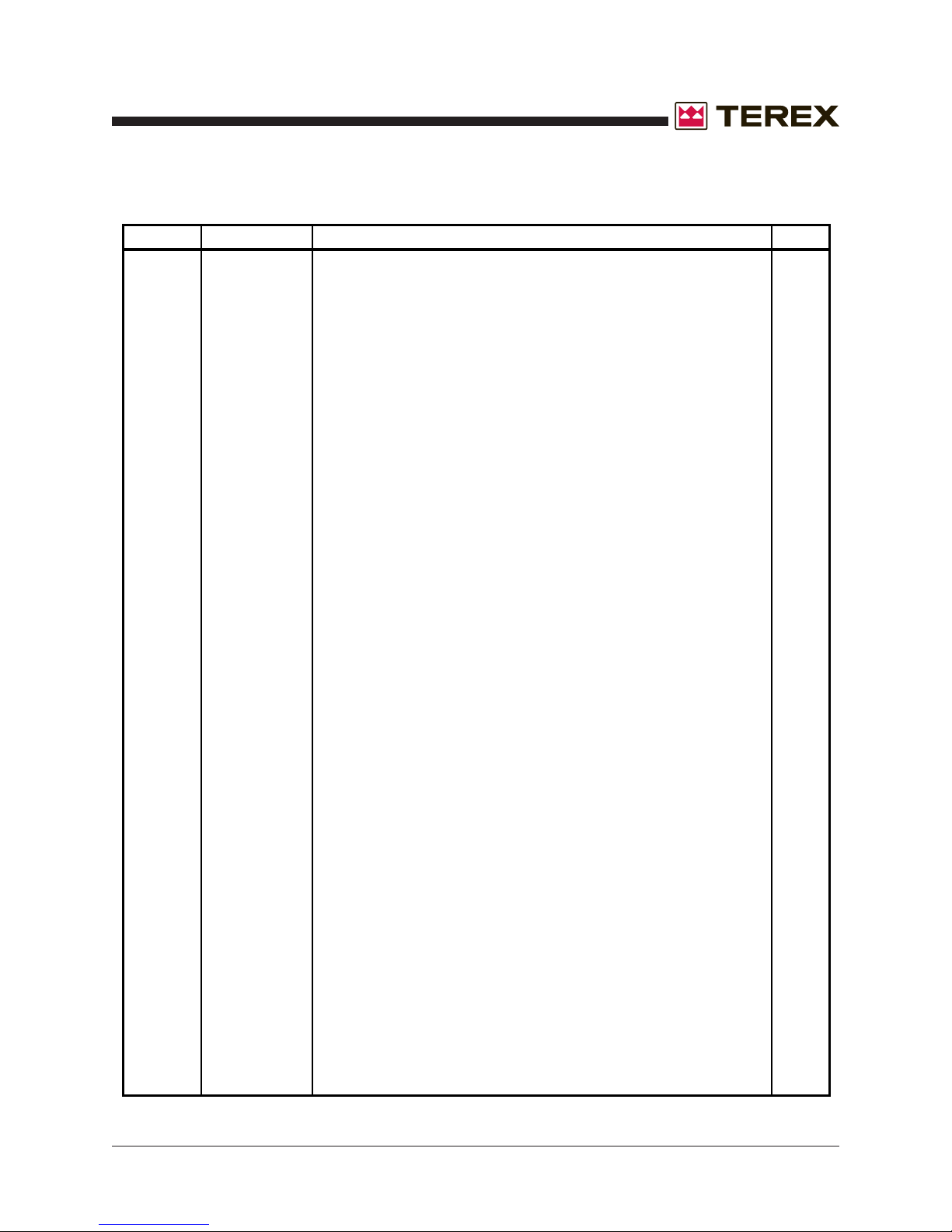
November 2007
Section 7 • Base Components
REV B
FIGURE 7-A
ITEM# PART# DESCRIPTON QTY.
1 890787 HOSE,FUEL,1/2" ID AR
2 796090 CLAMP,HOSE,9/16 TO 1-1/16", S/S, SIZE 10X5/8 1
3 C90200250 BARB,1/4" MNPT 1/2" ID HOSE 1
4 C90200400 FITTING,PICKUP&RETURN 1
5 895775 PIPE NIPPLE 2X3 1
6 C90500850 COUPLING,PIPE,2" NPT 1
7 796151 FUEL CAP 1
8 C91100300 NYLON TUBING 1
9 890787 HOSE,FUEL,1/2" ID AR
10 796090 CLAMP,HOSE,9/16 TO 1-1/16", S/S, SIZE 10X5/8 1
11 C90200300 BARB,3/8"X1/4"NPT,90 1
12 C90500800 COUPLING,PIPE,1/4" 1
13 896781 VALVE,CHECK 1
14 C90200400 FITTING,PICKUP&RETURN 1
15 C51600800 NUT,CLIP,1/4"-20X3/4" 3
16 186695 FUEL SENDER RING CAP 1
17 INCLUDED IN ITEM 18
18 C43200601 SENDER,FUEL LEVEL, VDO 1
19 INCLUDED IN ITEM 18
20 895371 VALVE,VACCUUM RELIEF 1
21 792750 CLAMP 7/16 TO 25/32 1
22 890790 HOSE FUEL 1/4X1/2 200# AR
23 C91001300 FITTING,BARB,3/8"NPT 1
24 NPN PURCHASE LOCALLY 1
25 CD21F050 ROD,LIFTING 2
26 C36560 NUT,1.125"-7 6
27 C33638 WASHER,LOCK,1.125" 6
28 C33024 WASHER,FLAT,1.125" 6
29 C54200700 SCREW,1/2"-13X 1" Z G5 8
30 991650 WASHER LOCK 1/2 8
31 C33600200 MOUNT,VIBRATION 40DURO 4
32 995790 CLEVIS PIN 1
33 C75240 LOCK WASHER 1/2 SBZ 2
34 C74967 HEX NUT 1/2-13 SBZ 2
35 C74972 FLAT WASHER 1/2 SBZ 2
36 C74954 SCREW,HEX,1/2"-13 X 2.5" 1
37 993440 SCREW 1/4-20NCX3/4 - NOT SHOWN 3
38 684070 CORD GRIP - NOT SHOWN 1
39 CD22F000 BASE, ALL MODELS 1
Part No. 833009 T50 Super Quiet Generator 7 - 3
Page 68
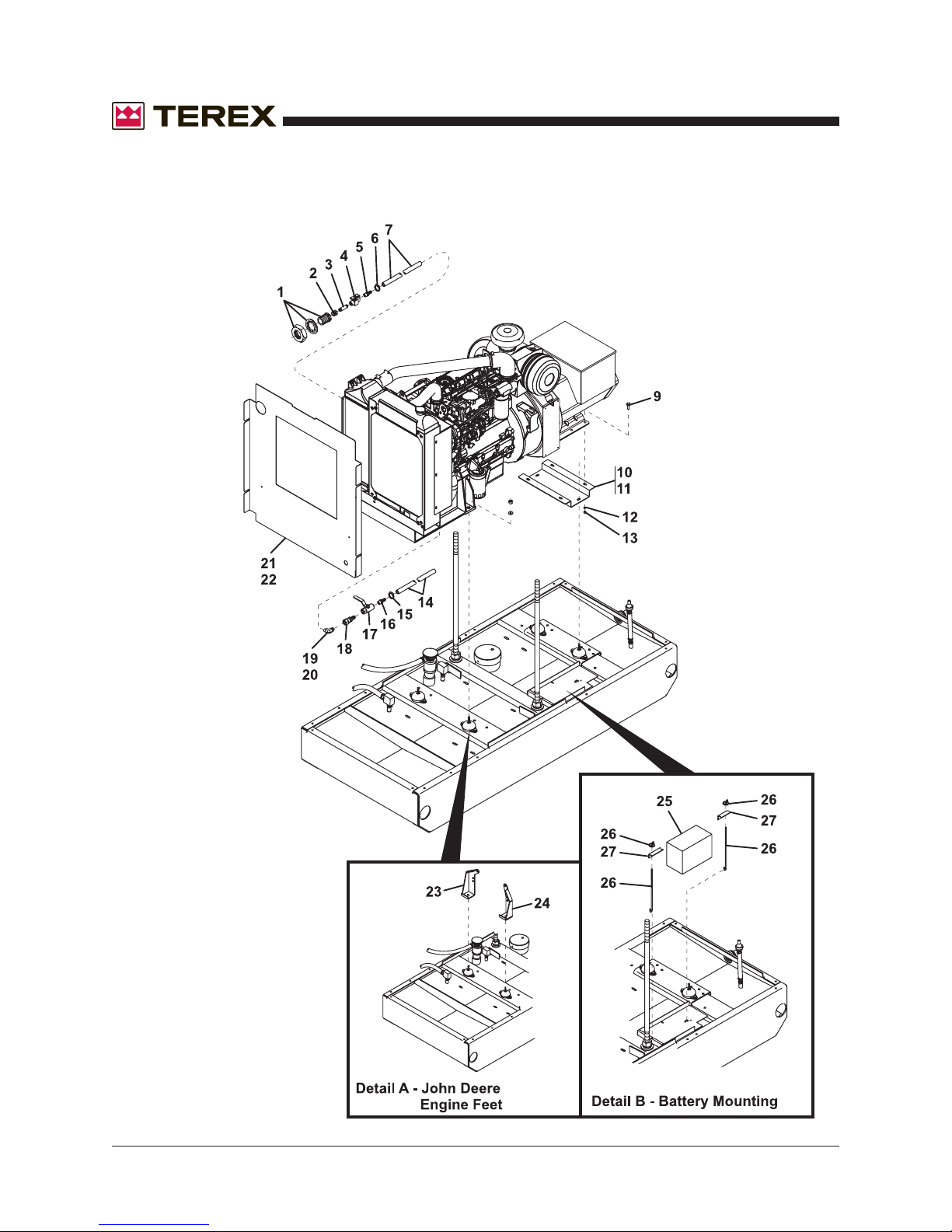
Section 7 • Base Components
October 2006
Figure 7-B
Base Components
REV A
7 - 4 T50 Super Quiet Generator Part No. 833009
Page 69
October 2006
Section 7 • Base Components
REV A
ITEM # PART # DESCRIPTION QTY.
1 C90202200 FITTING,BULK HEAD,1/2 NPT 1
2 C90700800 ADAPTER,1/2"X1/4" REDUCER 1
3 C90400900 NIPPLE,PIPE,1/4"X1.5" 1
4 C90800200 VALVE,NEEDLE,1/4"FPTX1/4" FPT 1
5 C90200600 BARB,3/8"X1/4"NPT 1
6 792750 CLAMP 7/16 TO 25/32 WITH LINER 2
7 C91100700 HOSE,FUEL,3/8" 3
8 C90200300 BARB,3/8"X1/4"NPT, 90DEGREE, T50J ONLY, NOT SHOWN 1
9 981660 SCREW,1/2-13NCX1-1/2 HHC,GRADE 5,ZP 4
10 CD32F010 HAT CHANNEL,T50J 1
11 CD32P010 HAT CHANNEL,T50P 1
12 990210 WASHER FLAT 1/2 4
13 990200 NUT LOCK NYLON INSERT 1/2-13NC GR 2 ZPIN 4
14 C91104400 HOSE,OIL DRAIN,3/4" 1
15 C90101500 CLAMP,9/16" X 1-1/16" WITH LINER 1
16 C90200900 BARB,3/4"X1/2"NPT 1
17 C90800100 VALVE,BALL,1/2" 1
18 C90701000 FITTING,SWIVEL,7/8-14 NUT,1/2-14 1
19 898521 FITTING,ELBOW,7/8-14 M FLARE X 18M, T50J 1
20 898421 FITTING,STR TRD,ELBOW, 45 7/8-14X3/4-16, T50P 1
21 CD34F020 BULKHEAD,AIR, T50J 1
22 CD34P020 BULKHEAD,AIR, T50P 1
23 CD31F010 FOOT,ENGINE, RIGHT, T50J 1
24 CD31F020 FOOT,ENGINE, RIGHT, T50P 1
25 261252 BATTERY WET 12V GRP34/78 AMERISTART 750 CCA 1
26 C33700800 HOOK, BATTERY HOLD DOWN, PAIR 1
27 CU22A252 ANGLE, BATTERY, HOLD-DOWN 1
Part No. 833009 T50 Super Quiet Generator 7 - 5
Page 70
Section 7 • Base Components
October 2006
This page intentionally left blank.
7 - 6 T50 Super Quiet Generator Part No. 833009
Page 71

October 2006
Section 8 • Cabinet Components
Section Eight
Cabinet
Components
Part No. 833009 T50 Super Quiet Generator 8 - 1
Page 72
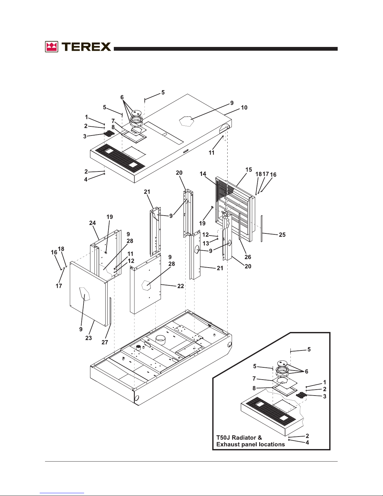
Section 8 • Cabinet Components
October 2006
Figure 8-A
Cabinet Components - Panels
REV A
8 - 2 T50 Super Quiet Generator Part No. 833009
Page 73
October 2006
Section 8 • Cabinet Components
REV A
FIGURE 8-A
ITEM # PART# DESCRIPTION QTY.
1 993422 SCREW, FLANGE 1/4-20 X 3/4" 4
2 C71014 FLAT WASHER 11/16" O.D. 8
3 CU59F005 EXHAUST HOLE COVER 1
4 990150 NUT 1/4-20, LOCK NYLON INSERT 4
5 990670 RIVET, POP, 3/16 X 1/2, SS 12
6 669174 PLATE DECK 1
7 CD59F015 RADIATOR ACCESS CAP 1
8 720440 WEATHERSTRIP, PER FT AR
9 C71100500 INSULATION, FOAM 1" THICK, PER SQ FT AR
10 CD59F000 HOUSING, TOP PANEL 1
11 C51601570 SCREW, FLANGE 3/8 X 3/4", PATCH AR
12 C54300600 WASHER, FLAT, 3/8" AR
13 C51601462 NUT, FLANGE, 3/8" AR
14 CF58T035 GUARD, LOUVER MESH 1
15 CD58F020 HOUSING, REAR PANEL 1
16 981605 SCREW, 3/8"-16 X 3" 8
17 990470 WASHER, LOCK, 3/8" 8
18 981120 WASHER, FLAT, 3/8" 8
19 C51600600 NUT, CLIP 8
20 CD52F020 HOUSING, REAR CORNER 2
21 CD57F010 HOUSING, DOOR STOP 2
22 CD52F030 HOUSING, LEFT FRONT CORNER 1
23 CD58F010 HOUSING, FRONT PANEL 1
24 CD52F010 HOUSING, RIGHT FRONT CORNER 1
25 GUU401100 TRIMLOCK SEAL, PER FT AR
26 680465 EDGE STRIP, PER FT AR
27 C72100400 WEATHERSTRIP, PER FT AR
28 GUU401000 INSULATION, FOIL, PER SQ FT AR
Part No. 833009 T50 Super Quiet Generator 8 - 3
Page 74
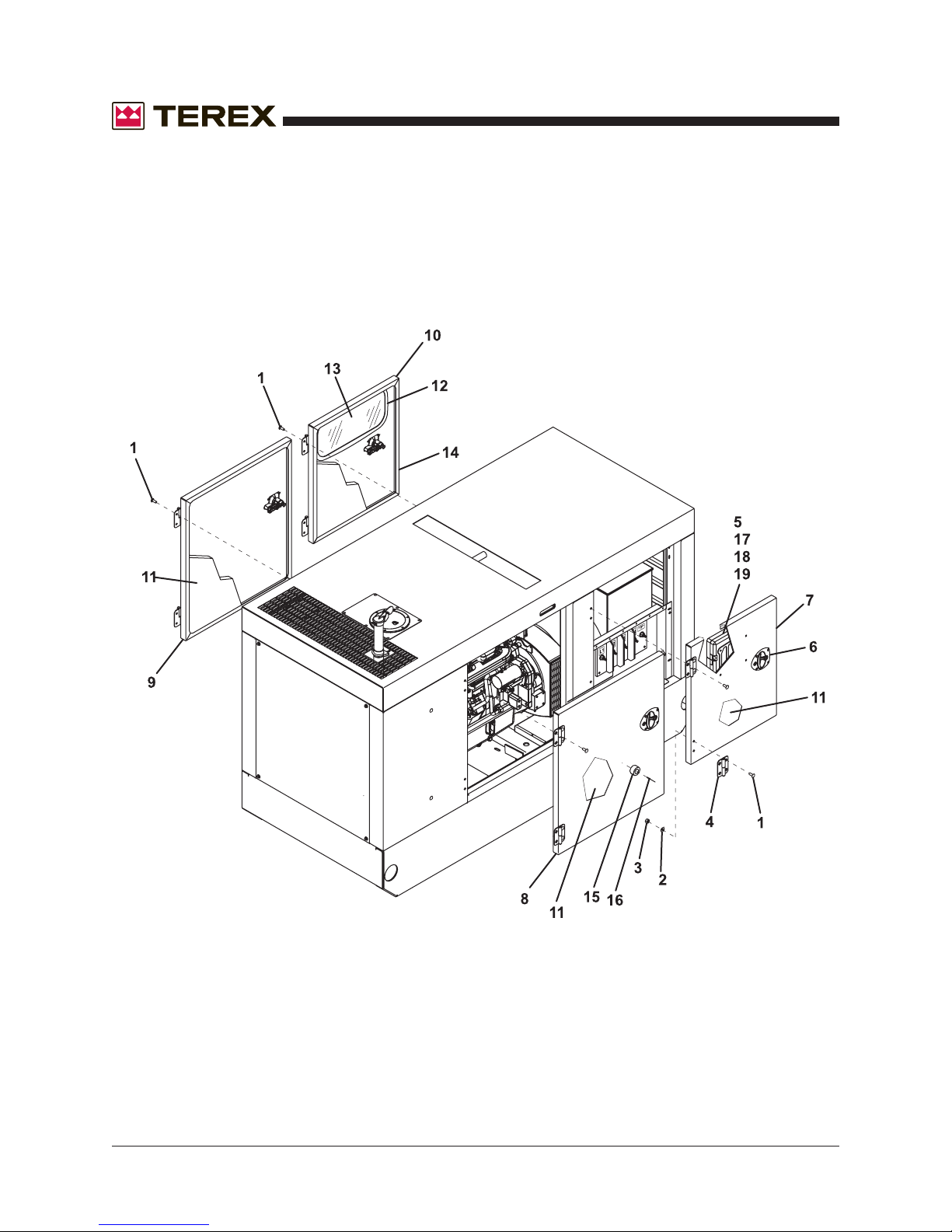
Section 8 • Cabinet Components
October 2006
Figure 8-B
Cabinet Components - Doors
REV A
8 - 4 T50 Super Quiet Generator Part No. 833009
Page 75
October 2006
Section 8 • Cabinet Components
REV A
FIGURE 8-B
ITEM # PART # DESCRIPTION QTY.
1 995701 SCREW, 1/4-20 X 1 32
2 990080 WASHER, FLAT, 3/8" 32
3 C37014 NUT,NYLOCK,10-24,Z 32
4 794891 HINGE,LIFT-OFF,STEEL 8
5 C53200100 LITERATURE BOX 1
6 C51200000 LATCH,BLACK,ALLEGIS 4
7 CD54F035 HOUSING DOOR 3PH 1
8 CD54F055 HOUSING DOOR ACCESS, LEFT 1
9 CD54F045 HOUSING DOOR ACCESS, RIGHT 1
10 CD54F025 HOUSING DOOR CTRL 1
11 C71100500 FOAM BLK URETHANE 1", PER SQ FT AR
12 C74100100 GASKET,WINDOW,CTRL DR, PER FT AR
13 CU54T021 WINDOW,CTRL DOOR 1
14 C73000100 TRIM LOCK,1/4", PER FT AR
15 C51400200 STOP,DOOR,RUBBER 2
16 C41037 RIVET 2
17 C74419 SCREW, CARRIAGE,1/4-20 4
18 C71014 FLAT WASHER 4
19 990150 NUT LOCK NYLON INSERT, 1/4-20 4
Part No. 833009 T50 Super Quiet Generator 8 - 5
Page 76
Section 8 • Cabinet Components
October 2006
This page intentionally left blank.
8 - 6 T50 Super Quiet Generator Part No. 833009
Page 77

October 2006
Section 9 • Control Box Components
Section Nine
Control Box
Components
Part No. 833009 T50 Super Quiet Generator 9 - 1
Page 78
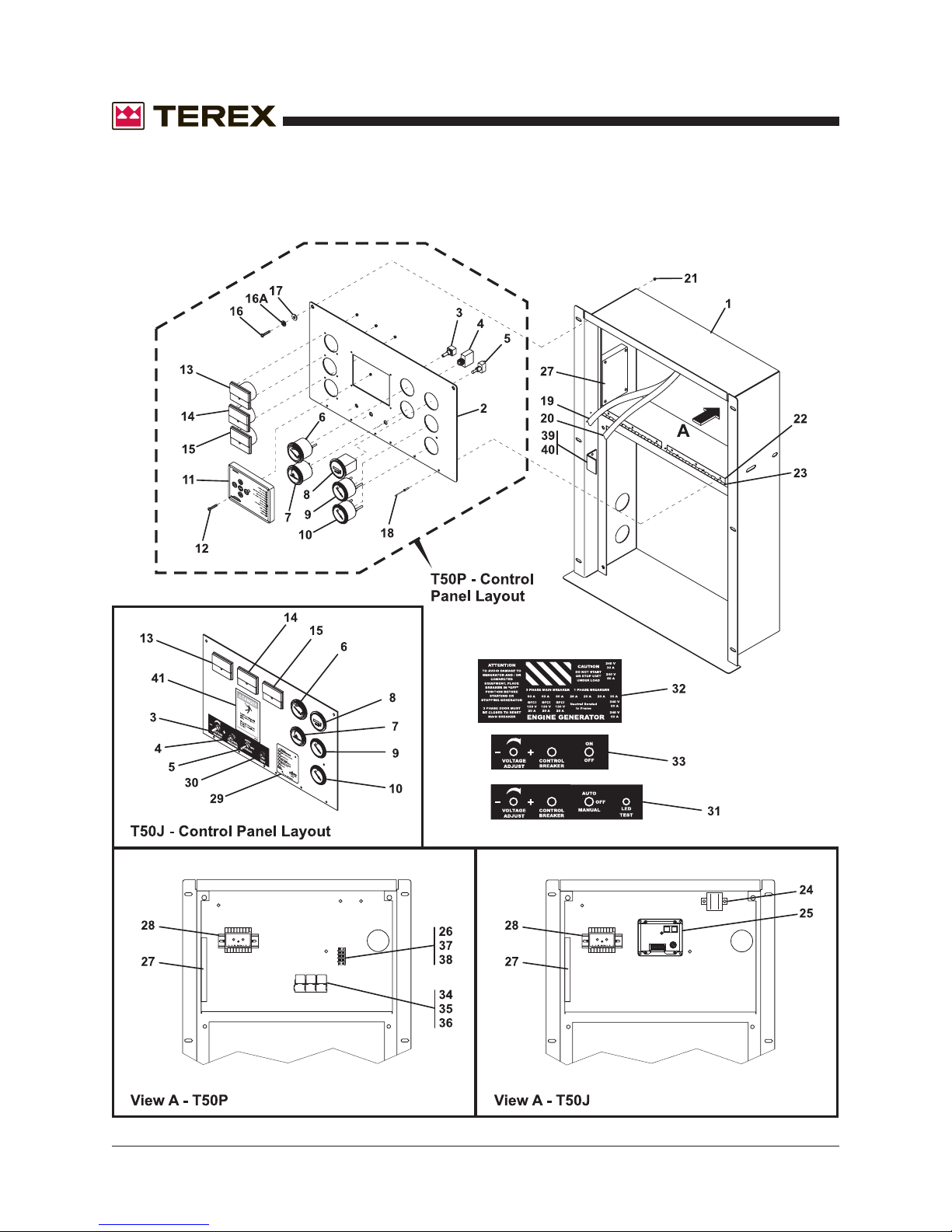
Section 9 • Control Box Components
October 2006
Figure 9-A
Control Panel - Upper
REV A
9 - 2 T50 Super Quiet Generator Part No. 833009
Page 79
October 2006
Section 9 • Control Box Components
REV A
FIGURE 9-A
ITEM # PART # DESCRIPTION QTY.
1 CD42F010 CONTROL PAN ASSY 1
2 CU42Q031 CONTROL PANEL, DYNAGEN 1
2 CU42Q032 CONTROL PANEL, CASCADE 1
3 C42200500 POTENTIOMETER, VOLTAGE 1
4 682070 BREAKER MINI 1P 15A 1
5 C42202900 SWITCH,TOGGLE 1
6 C43100800 GAUGE,DC VOLT 1
7 C43200400 GAUGE,OIL PRESSURE 1
8 260360 HOURMETER 12V DC 1
9 C43200300 GAUGE,WATER TEMP,12V 1
10 C43200600 GAUGE,FUEL 1
11 261341 CASCADE CONTROLLER 1
12 INCLUDED IN ITEM 11
13 C43100600 METER,VOLT 1
14 C43100400 METER,FREQUENCY 1
15 C43101000 METER,AMP,0-200 1
16 R980195 SCREW,1/4-20NCX3/4 6
16A 990400 WASHER LOCK 1/4 6
17 981745 WASHER,FLAT,1/4" 6
18 992040 RIVET POP 3/16X.602 10
19 CB45A112 HARNESS,AC CTRL/PNL 1
20 CU45A100 HARNESS,CTRL,UNIVERSAL 1
21 C51600800 NUT,CLIP,1/4"-20X3/4" 6
22 CU43A050 PLASTIC 1/8"X10.5"X33 1
23 C51200201 HINGE,PIANO,9",SS 1
24 C42400700 SOLENOID 1
25 C33203000 CONTROLLER ELEC.GOV DPG2104 1
26 C42404000 TERMINAL STRIP,6 POS 1
27
28 C42401700 RELAY,OVER CURRENT 1
29 C42400810 SHUTDOWN,DYNAGEN,ECU-ES52 1
30 686747 SWITCH,SPST MOMENTARY 1
31 853810 DECAL: CONTROL PANEL 1
32 853813 DECAL: KIT-RECEPTACLES 1
33 853838 DECAL: CONTROL PANEL 1
34 CDWV40150 RELAY,50A,BOSCH 3
35 CDWV40151 RELAY BASE,50A,BOSCH 3
36 CDWV40152 RELAY PIN 12
37 R660115 JUMPER TERMINAL STRIP 1
38 R660715 DIODE,6AMP-50PIV 1
39 CU42T070 BRACKET,LATCH 1
40 C51601550 SCREW,SELF-TAPPING,#10 2
41 CU51A122 DECAL: HIGH VOLTAGE 1
SX460 OR
SX465
AVR - CHECK UNIT BEFORE ORDERING 1
Part No. 833009 T50 Super Quiet Generator 9 - 3
Page 80
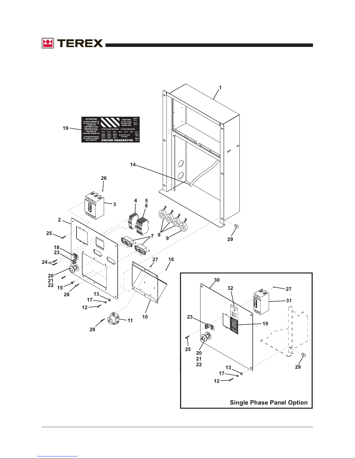
Section 9 • Control Box Components
October 2006
Figure 9-B
Control Panel - Lower
REV A
9 - 4 T50 Super Quiet Generator Part No. 833009
Page 81
October 2006
Section 9 • Control Box Components
REV A
FIGURE 9-B
ITEM # PART # DESCRIPTION QTY.
1 CD42F010 CONTROL PAN ASSY 1
2 CD41F020 PANEL,1PH,D-SERIES 1
3 C42104800 BREAKER,150A,SHUNTTRIP 1
4 C42103400 BREAKER,20A,120/240V 1
5 C42103600 BREAKER,50A,120/240V 1
6 C42103600 BREAKER,50A,120/240V 1
7 684640 RECEPTACLE 20A 120V DUPLEX W/GFI 2
8 C42500100 TRANSFORMER,100:5 3
9 C42500200 TRANSFORMER,200:5 1
9 C42500200 TRANSFORMER,200:5 ( 1 PHASE ONLY) 3
10 CU41S030 TEMP POWER SLOPE 1
11 C47100300 RECEPTACLE,TWISTLOCK 2
12 R980195 SCREW,1/4-20NCX3/4 6
13 981745 WASHER,FLAT,1/4" 6
14 CU45A010 HARNESS,AC/GEN 1
15 C51601442 SCREW,FLANGE,1/4"-20 4
16 990150 NUT LOCK NYLON INSERT, 1/4-20 6
17 990400 WASHER LOCK 1/4 6
18 853752 DECAL: REMOTE START CN 1
19 853813 DECAL: KIT-RECEPTACLES 1
20 66812 E-STOP, PUSH BUTTON 1
21 686662 EMERGENCY STOP, FACE PLATE 1
22 66817 EMERGENCY STOP, BASE 1
23 671278 BINDING POST FOR REMOTE START 1
24 C73716 SCREW,#6-32X1/2" 12
25 C27514 SCREW,#10-24X3" Z KEG 4
26 C37810 NUT,COUPLER,#10-24X3/4 4
27 R980900 NUT,LOCK NYLON INSERT #8-32NF 8
28 C54400100 SCREW, SET, 8-32X1/2" 8
29 C51600800 NUT,CLIP,1/4"-20X3/4" 6
30 CD41P020 PANEL,1PH,D-SERIES 1
31 683875 BREAKER, 200A, 2 POLE 1
32 CU51A122 DECAL: HIGH VOLTAGE 1
Part No. 833009 T50 Super Quiet Generator 9 - 5
Page 82
Section 9 • Control Box Components
October 2006
This page intentionally left blank.
9 - 6 T50 Super Quiet Generator Part No. 833009
Page 83

October 2006
Section 10 • Distribution Panel
Section Ten
Distribution
Panel
Part No. 833009 T50 Super Quiet Generator 10 - 1
Page 84
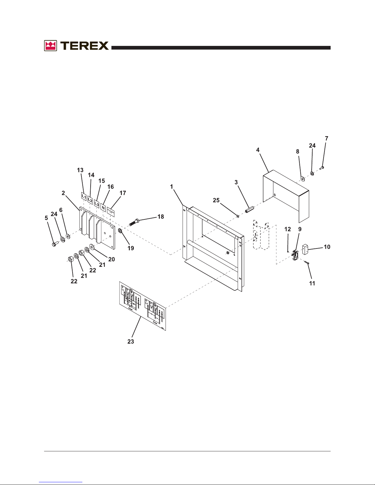
Section 10 • Distribution Panel
October 2006
Figure 10-A
Distribution Panel
REV A
10 - 2 T50 Super Quiet Generator Part No. 833009
Page 85
October 2006
Section 10 • Distribution Panel
REV A
FIGURE 10-A
ITEM # PART # DESCRIPTION QTY.
1 CU43T020 PAN 3PH DIST 1
2 CU43A041 DIST LUG PANEL 1
3 C37819 NUT,COUPLER,3/8"-16 4
4 CF44T045 DIST. LUG COVER 1
5 C94903 SCREW, 3/8-16X1 1/4Z 4
6 994340 SCREW,#6-32X5/8" 4
7 990160 SCREW 3/8-16NCX3-3/4 4
8 994830 WASHER,LOCK,M10 4
9 C42200702 PLUNGER (ACTUATOR) 1
10 C42200701 SWITCH,SNAP-ACTION 1
11 INCLUDED IN ITEM 9
12 INCLUDED IN ITEM 9
13 CU51A400 DECAL: L1,L2,L3,N 1
14 INCLUDED IN ITEM 13
15 INCLUDED IN ITEM 13
16 INCLUDED IN ITEM 13
17 851820 DECAL: SYMBOL FOR GROUND 1
18 C74954 SCREW,HEX,1/2"-13 X 2.5" 5
19 995970 WASHER LOCK STAR 1/2 5
20 C74972 FLAT WASHER 1/2 SBZ 5
21 C75240 LOCK WASHER 1/2 SBZ 10
22 C74967 HEX NUT 1/2-13 SBZ 10
23 852255 3PH DIST PNL 1
24 994830 WASHER,LOCK,M10 8
25 990340 WASHER FLAT 1/4 4
Part No. 833009 T50 Super Quiet Generator 10 - 3
Page 86
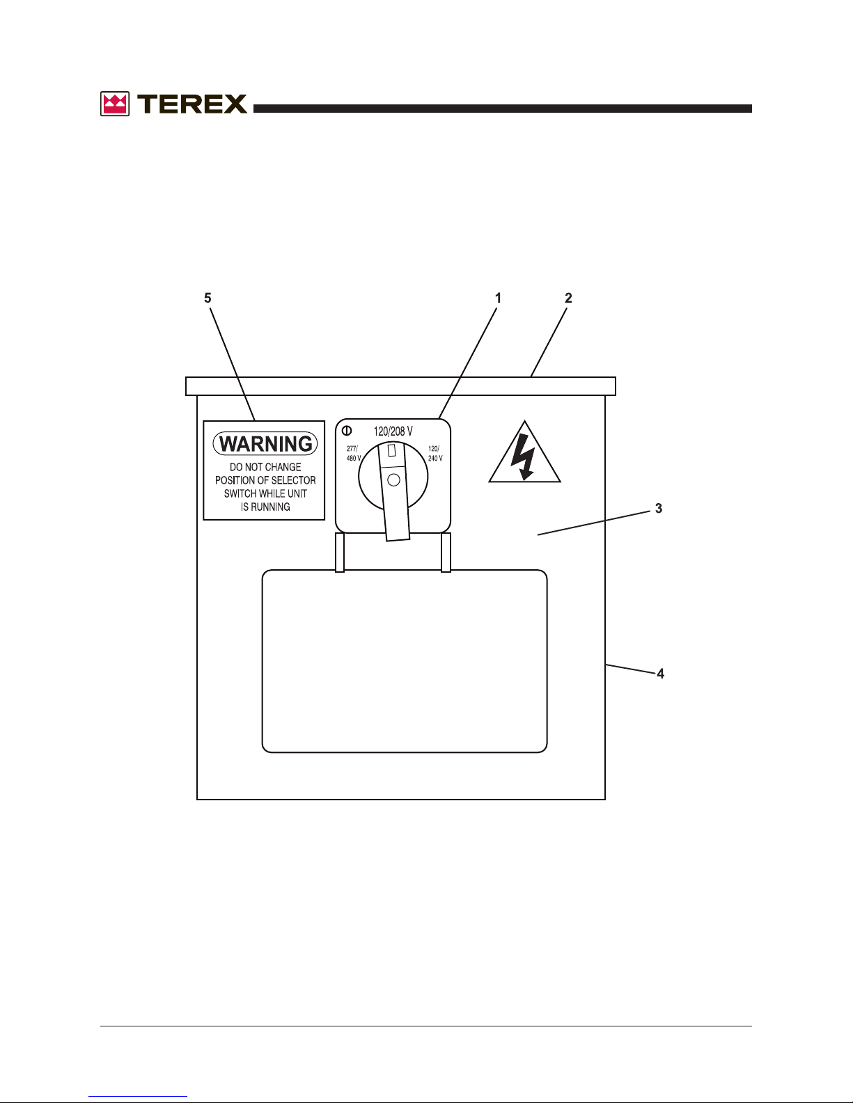
Section 10 • Distribution Panel
October 2006
Figure 10-B
Voltage Selector Switch
REV A
10 - 4 T50 Super Quiet Generator Part No. 833009
Page 87
October 2006
Section 10 • Distribution Panel
REV A
FIGURE 10-B
ITEM # PART # DESCRIPTION QTY.
1 C42202402 VOLTAGE SELECTOR SWITCH 1
2 CD42I031 BCI, FRAME EXTENSION, BACK 1
3 CD42I030 BCI, FRAME EXTENSION, FRONT 1
4 CD42I040 BCI. FRAME EXTENSION, SIDE 2
5 CL-008 DECAL, DO NOT CHANGE POSITION 1
Part No. 833009 T50 Super Quiet Generator 10 - 5
Page 88
Section 10 • Distribution Panel
October 2006
This page intentionally left blank.
10 - 6 T50 Super Quiet Generator Part No. 833009
Page 89

October 2006
Section 11 • Engine & Genset Components
Section Eleven
Engine &
Genset
Components
Part No. 833009 T50 Super Quiet Generator 11 - 1
Page 90
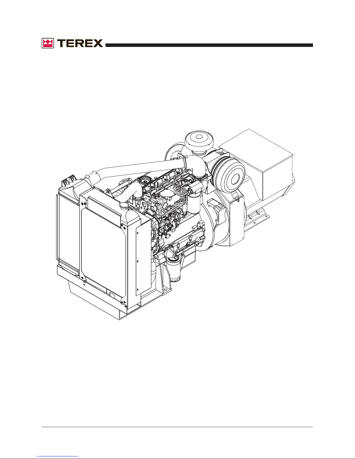
Section 11 • Engine & Genset Components
October 2006
Figure 11-A
Engine Genset Assembly - Perkins 1104C-44G1
REV A
11 - 2 T50 Super Quiet Generator Part No. 833009
Page 91
November 2007
Section 11 • Engine & Genset Components
REV B
FIGURE 11-A
ITEM # PART # DESCRIPTION QTY.
1 116843 GENSET,40KW PERKINS/NEWAGE 1
2 630947 GENERATOR,NEWAGE,40KW, BCI184J1A1232A, PERKINS 1
3 630992 GENERATOR,NEWAGE,40KW, SINGLE PHASE, PERKINS 1
4 830001 MANUAL, BCI GENERATOR 1
5 836427 RECTIFIER SERVICE KIT 1
6 732266PP ENGINE,PERKINS,40KW, T2, RE51215, 1104C.44G2 1
7 866047 AIR FILTER ASSY. 1
8 866049 ELEMENT, INNER 1
9 866048 ELEMENT, OUTER 1
10 741921 OIL FILTER 1
11 741923 FUEL FILTER 1
12 C42300100 LOW OIL PRESSURE SWITCH 1
13 C42300400 LOW OIL SENDER 1
14 C90700200 LOP SENDER ADAPTER 1
15 866064 SWITCH, COLD START ADVANCE 1
16 C42300500 HIGH TEMP SWITCH 1
17 C42300600 MAGNETIC PICK UP 1
18 866054 BELT 1
19 866064 WATER SEPARATOR 1
20 866055 RADIATOR 1
21 866056 FAN 1
22 866062 HOSE, UPPER 1
23 866063 HOSE, LOWER 1
24 C91100700 FUEL HOSE, 3/8" 1
25 890790 FUEL HOSE, 1/4" 1
26 866057 FAN GUARD 1
27 866058 FAN GUARD 1
28 866059 FAN GUARD, SMALL 1
29 866065 TEMP SWTICH/COLD START ADVANCE 1
30 C90700500 ADAPTER, MAG PICKUP 1
31 C33200500 FILTER, FUEL, 245R30 W/WATER SEPERATOR ASSEMBLY 1
32 CR25-P WATER SEPARATOR, ELEMENT ONLY 1
Part No. 833009 T50 Super Quiet Generator 11 - 3
Page 92
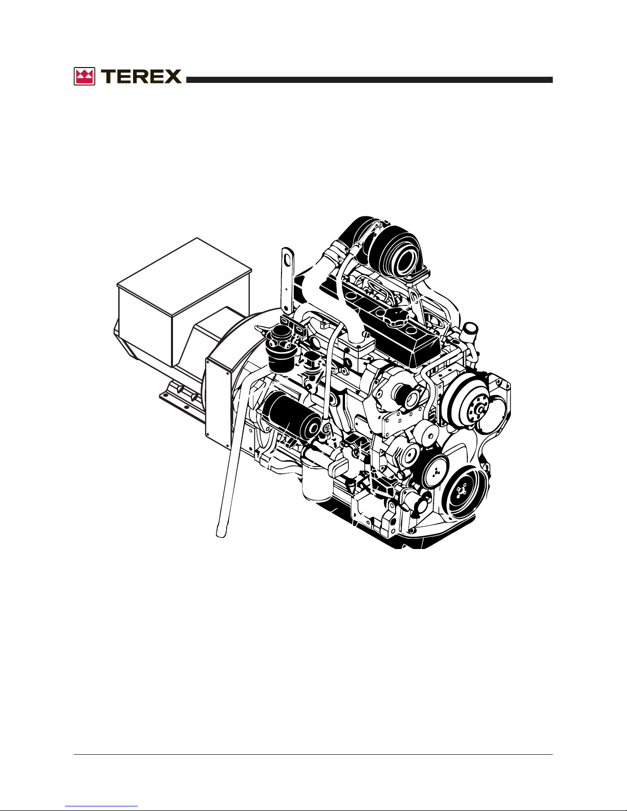
Section 11 • Engine & Genset Components
October 2006
Figure 11-B
Engine Genset Assembly - John Deere 4045 DF270
REV A
11 - 4 T50 Super Quiet Generator Part No. 833009
Page 93
November 2007
Section 11 • Engine & Genset Components
REV B
FIGURE 11-B
ITEM # PART # DESCRIPTION QTY.
1 116853 GENSET, T50J, JD/NEWAGE, TIER 2 1
2 630944 GENERATOR,NEWAGE,40KWJD/I,4,BCI184J1L202A 1
3 732121 ENGINE,JD,4045DF270,T2, 50KVA/40KW,164P 1
4 830001 MANUAL, BCI GENERATOR 1
5 836427 RECTIFIER SERVICE KIT 1
6 33100702 AIR FILTER ASSY. 1
7 NA ELEMENT, INNER 1
8 33100703 ELEMENT, OUTER 1
9 741915 OIL FILTER 1
10 741916 FUEL FILTER 1
11 C42300100 LOW OIL PRESSURE SWITCH 1
12 C90700200 LOP SENDER ADAPTER 1
13 C42300400 LOW OIL SENDER 1
14 C42300500 HIGH TEMP SWITCH 1
15 C42300600 MAGNETIC PICK UP 1
16 741942 BELT 1
17 CR25P WATER SEPARATOR 1
18 C33300300 RADIATOR 1
19 C33301401 FAN 1
20 C91102100 HOSE, UPPER 1
21 C91109600 HOSE, LOWER 1
22 C91100700 FUEL HOSE, 3/8" 1
23 890790 FUEL HOSE, 1/4" 1
24 C33300900 FAN GUARD 1
25 CD34F030 FAN SHROUD 1
26 C33202900 ACTUATOR 1
27 C42301700 SWITCH, TEMP, W/SENDER, 1/2" THREAD, VDO 1
28 C33200500 FILTER, FUEL, 245R30, W/WATER SEPARATOR ASSEMBLY 1
29 791580 CLAMP 1-9/16" TO 2-1/2" WITH LINER 4
30 C91101201 ELBOW, RUBBER, 2" 90 DEGREE 2
31 CD35F030 PIPE, AIR BREATHER 40KW 1
Part No. 833009 T50 Super Quiet Generator 11 - 5
Page 94
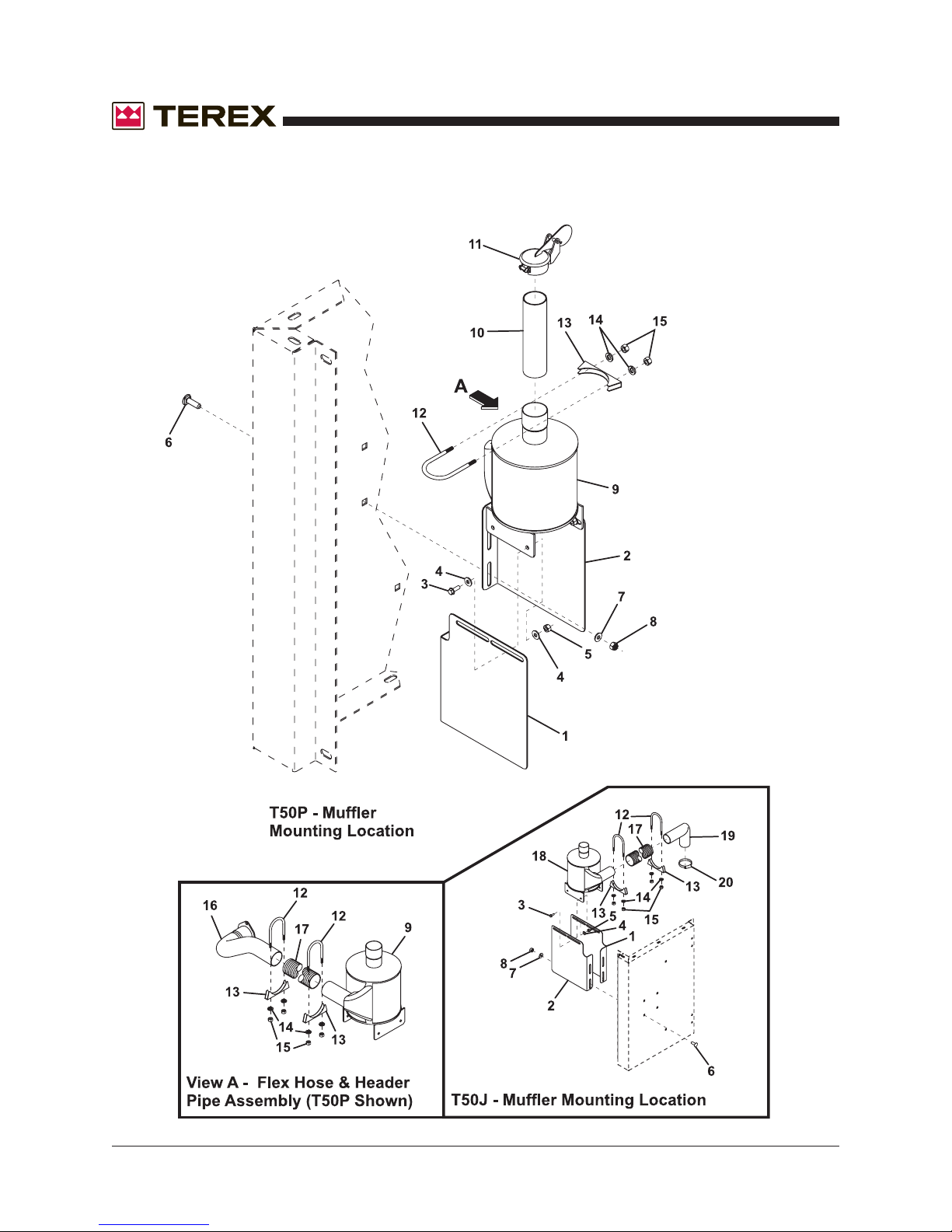
Section 11 • Engine & Genset Components
October 2006
Figure 11-C
Engine Muffler Assembly - John Deere & Perkins
REV A
11 - 6 T50 Super Quiet Generator Part No. 833009
Page 95
November 2007
Section 11 • Engine & Genset Components
REV B
FIGURE 11-C
ITEM # P ART # DESCRIPTION QTY.
1 CD33P045 MUFFLER EXTENSION, RIGHT 1
2 CD33P035 MUFFLER EXTENSION, LEFT 1
3 C51601570 SCREW,FLANGE,3/8" X 3/4" 4
4 990080 WASHER FLAT 3/8 8
5 C51601462 NUT, FLANGE, 3/8"-16 4
6 C21819 SCREW,CARRIAGE,3/8"-16 4
7 990210 WASHER FLAT 1/2 4
8 C51601462 NUT, FLANGE, 3/8"-16 4
9 CD33P010 MUFFLER, ASSEMBLY, T50-P 1
10 CD33F052 PIPE, EXHAUST 1
11 C33503401 CAP,RAIN,2.5" 1
12 C90101000 CLAMP,U-BOLT,2.5" 3
13 INCLUDED IN ITEM 12 3
14 INCLUDED IN ITEM 12 3
15 INCLUDED IN ITEM 12 3
16 CD33P020 EXHAUST ASSY., T50-P 1
17 C91100601 TUBING,FLEX,EXHAUST 1
18 CD33F050 MUFFLER,ASSY., T50-J 1
19 CD33F060 EXHAUST PIPE ASSY., T50-J 1
20 760453 CLAMP V-BAND EXHAUST 1
Part No. 833009 T50 Super Quiet Generator 11 - 7
Page 96
Section 11 • Engine & Genset Components
October 2006
This page intentionally left blank.
11 - 8 T50 Super Quiet Generator Part No. 833009
Page 97

October 2006
Section 12 • Trailer Components
Section Twelve
Trailer
Components
Part No. 833009 T50 Super Quiet Generator 12 - 1
Page 98
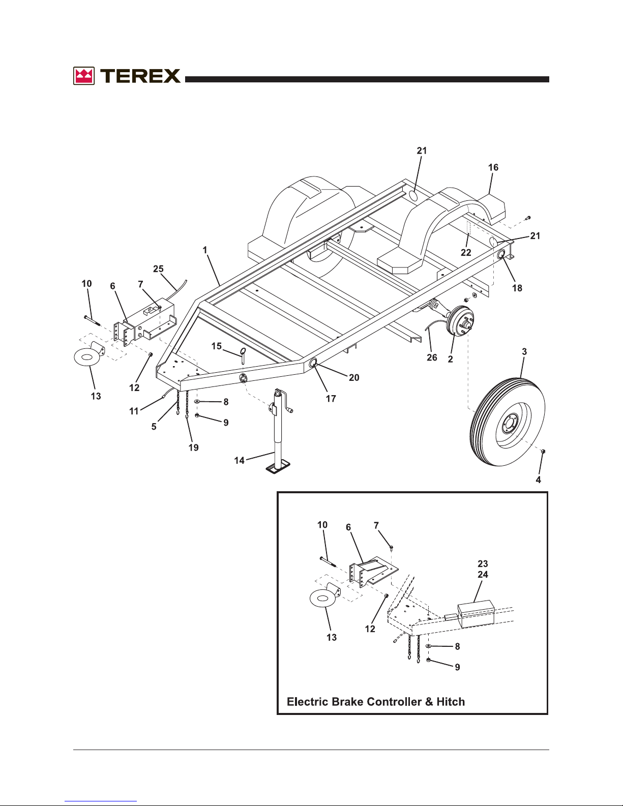
Section 12 • Trailer Components
October 2006
Figure 12-A
Trailer Components
REV A
12 - 2 T50 Super Quiet Generator Part No. 833009
Page 99
October 2006
Section 12 • Trailer Components
REV A
FIGURE 12-A
ITEM # PART # DESCRIPTION QTY.
1 124880 TRAILER, GENSET, D-SERIES, HYDRAULIC BRAKES 1
1 124885 TRAILER, GENSET, D-SERIES, ELECTRIC BRAKES 1
2 834238 AXLE, HYDRAULIC TRAILER BRAKES 1
2 834239 AXLE, ELECTRIC TRAILER BRAKES 1
3 841063 TIRE AND WHEEL MOUNTED, ST225/75R15D 2
4 840396 LUG NUT 12
5 834208 SAFETY CHAIN 2
6 834212 HITCH MOUNT, FOR TRAILER WITH ELECTRIC BRAKES 1
6 834241 HITCH MOUNT, INCLUDES HYDRAULIC ACTUATOR 1
7 C15309 BOLT 6
8 990210 WASHER 6
9 993170 NUT 6
10 834213 BOLT 2
11 834214 CONNECTOR, 6 PIN 1
12 834215 NUT 2
13 834216 RING HITCH, STANDARD 1
14 834237 JACK 1
15 834218 PIN 1
16 840082 FENDER, PLASTIC 2
17 834221 AMBER CLEARANCE LIGHT 2
18 834223 RED CLEARANCE LIGHT 2
19 834209 C-HOOK, SAFETY CHAIN 2
20 834232 CLEARANCE LIGHT MOUNTING KIT 4
21 834234 STOP, TAIL LIGHT W/GROMMET AND PLUG 2
22 834236 TAG LIGHT KIT 1
23 834247 ELECTRIC BOX 1
24 834248 WIRE HARNESS FOR ELECTRIC BOX 1
25 834243 HYDRAULIC LINE, METAL 1
26 834245 HYDRAULIC HOSE KIT 1
Part No. 833009 T50 Super Quiet Generator 12 - 3
Page 100
Section 12 • Trailer Components
October 2006
This page intentionally left blank.
12 - 4 T50 Super Quiet Generator Part No. 833009
 Loading...