

Page 1
Page 2

Operator's Manual First Edition • First Printing
Important
Read, understand and obey these safety rules and
operating instructions before operating this
machine.
Only trained and authorized personnel shall be
permitted to operate this machine. This manual
should be considered a permanent part of your
machine and should remain with the machine at all
times. If you have any questions, call Terex.
Contents
Page
Introduction ...........................................................1
Symbol and Hazard Pictorials Definitions .............4
General Safety......................................................6
Operation Safety ...................................................8
Legend ................................................................12
Inspections .........................................................16
Setup ..................................................................22
Operating Instructions......................................... 24
Transport Instructions ......................................... 28
Lifting Instructions...............................................30
Towing Instructions ............................................. 31
Maintenance .......................................................33
Specifications ..................................................... 36
Serial Number Registration .................................40
Receipt of Delivery Checklist .............................. 40
Contact us:
Copyright © 2009 by Terex
Internet: www.terex.com
Terex Light Construction Division
590 Huey Road
Rock Hill, SC 29730
First Edition: First Printing, June 2009
Printed on recycled paper
Printed in U.S.A.
T180 • T240 Part No. 140435
Page 3

First Edition • First Printing
Operator's Manual
Introduction
Description of equipment
The engine/generator assembly consists of a diesel
engine combined with an electrical generator. This
assembly is firmly bolted together to form an
integral unit and does not require anything other
than routine maintenance.
The engine is equipped with a 12-volt starter and
can be wired for remote starting capability at the
control panel.
A dry-element air cleaner is standard equipment to
ensure a clean air supply, and a fuel/water
separator is included for additional fuel system
protection.
A governor on the engine provides a stable
operating speed under varying load conditions.
The generator is equipped with a solid-state
voltage regulator to stabilize the output voltage
under these same conditions. Figures and
schematics of both the governor and regulator are
provided in the service manual.
An automatic shut down system is incorporated in
the generator set to sense low oil pressure and/or
high coolant temperature. In either case, the
engine/generator assembly will automatically shut
down to protect the engine.
The enclosure for the generator set is constructed
from 12 or 14-gauge sheet metal to ensure rigidity,
and is bolted together to allow easy access to
major components if necessary. Four lockable
hinged access doors are provided for routine
operation and maintenance.
The enclosure on the Super Quiet Generator is
specifically designed for a high degree of sound
attenuation. This allows the generator set to be
operated in noise-sensitive environments. The
interior of the enclosure is coated with sounddampening polymer foam that is highly effective in
noise suppression.
A high ambient temperature radiator and an integral
exhaust and muffler system are contained within
the enclosure as standard equipment.
A center-point lifting attachment is located on top
of the enclosure to allow crane lifting of the entire
unit.
The generator set can be mounted on a trailer
equipped for highway operation which is available
as an option. Standard trailers do not come
equipped with brakes but hydraulic surge brakes or
electric brakes are available as an option.
A diesel fuel tank is incorporated within the base of
the unit to ensure an uninterrupted operating cycle
under a full load. The engine/generator assembly is
mounted to the base using high durometer
vibration isolators.
Part No. 140435 T180 • T240 1
Page 4
Operator's Manual First Edition • First Printing
Introduction
Owners, Users and Operators:
Terex appreciates your choice of our generator for
your application. Our number one priority is user
safety, which is best achieved by our joint efforts.
We feel that you make a major contribution to
safety if you, as the generator users and operators:
1 Comply with employer, job site and
governmental rules.
Danger
Failure to obey the instructions and
2 Read, understand and follow the instructions
in this and other manuals supplied with this
generator.
3 Use good safe work practices in a
commonsense way.
safety rules in this manual will result
in death or serious injury.
Do Not Operate Unless:
4 Only have trained/certified operators,
directed by informed and knowledgeable
supervision, operating the generator.
You learn and practice the principles of safe
generator operation contained in this operator's
manual.
If there is anything in this manual that is not clear
or which you believe should be added, please send
your comments to the Terex Service Department.
www.terex.com
1 Avoid hazardous situations.
Know and understand the general safety
rules before going on to the next section.
2 Always perform a pre-operation inspection.
3 Follow the setup instructions.
4 Follow the operating, transport and
towing instructions.
5 Only use the generator as it was intended.
You read, understand and obey the
manufacturer's instructions and safety rules —
safety and operator's manuals, and decals.
You read, understand and obey employer's
safety rules and all applicable governmental
regulations.
You are properly trained to safely operate the
generator.
2 T180 • T240 Part No. 140435
Page 5
First Edition • First Printing
Operator's Manual
Introduction
Hazard Classification
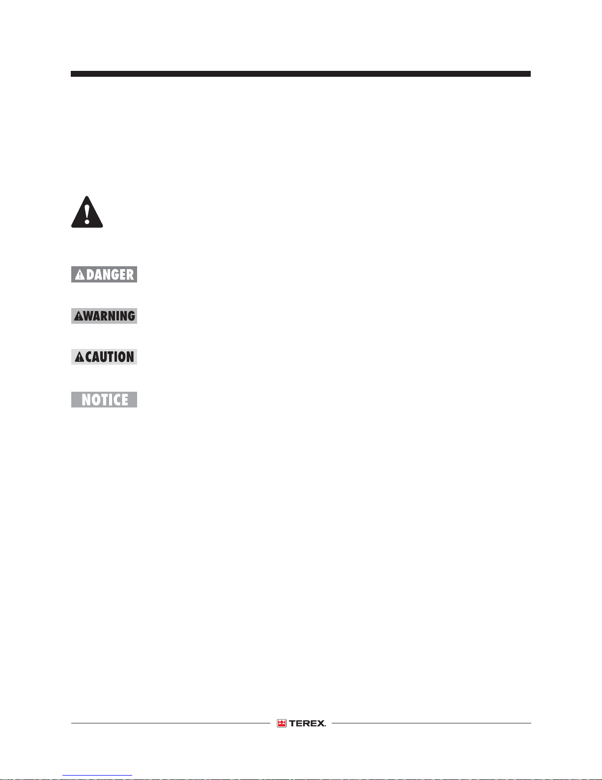
Terex uses symbols, color coding and signal words
to identify the following:
Safety alert symbol—used to alert
you to potential personal injury
hazards. Obey all safety
messages that follow this symbol
to avoid possible injury or death.
Indicates a hazardous situation
which, if not avoided, will result in
Red
Orange
Yellow
Blue
death or serious injury.
Indicates a hazardous situation
which, if not avoided, could result
in death or serious injury.
Indicates a hazardous situation
which, if not avoided, could result
in minor or moderate injury.
Indicates a property damage
message.
Intended Use
This generator set is intended to be used only to
supply electrical power to a work site.
Safety Sign Maintenance
Replace any missing or damaged safety signs.
Keep operator safety in mind at all times. Use mild
soap and water to clean safety signs. Do not use
solvent-based cleaners because they may damage
the safety sign material.
Part No. 140435 T180 • T240 3
Page 6
Operator's Manual First Edition • First Printing
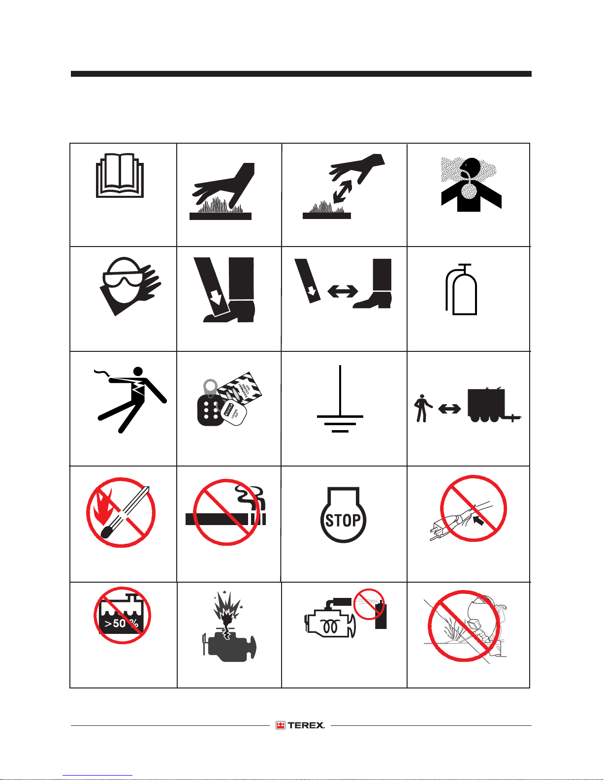
Symbol and Hazard Pictorials Definitions
Read the
operator’s
manual
Burn Hazard
Do not touch. Allow
surface to cool
Carbon Monoxide
Poisoning Hazard
Wear protective
clothing and eye wear
Electrocution Hazard
Hazardous voltage
Crushing Hazard
Lock out/tag out Earth ground
No smokingNo open flames
Keep clear of
leveling jack
Stop the engine
Fire extinguisher
Stay clear
Check for damaged
cords
Coolant in radiator
should not be more
than 50% antifreeze
4 T180 • T240 Part No. 140435
Engine explosion
Do not use ether or any
high energy engine
starting aids
Unauthorized welding
Page 7

First Edition • First Printing
Burn Hazard. Fuel
and fumes can
explode and burn.
Symbol and Hazard Pictorials Definitions
Explosion Hazard
Burn Hazard
Operator's Manual
Flames and Sparks
Hazard
Part No. 140435 T180 • T240 5
Page 8

Operator's Manual First Edition • First Printing
General Safety
Safety Signs and Locations (Word Decals)
DANGER
DANGER
Burn Hazard
No smoking. No
Fuel and fumes
flame. Stop
can explode
engine.
and burn.
WARNING
Crushing hazard.
Lowering the leveling jack onto
a person's foot can result in
serious injury.
Keep clear of the leveling jack
before lowering.
133007 proto
DANGER
Explosion / Burn Hazard
Ignition of explosive gases or contact with corrosive
acid will cause death, burns or blindness
Keep all open flames and sparks away. Wear
personal protective equipment, including face
shield, gloves and long sleeve shirt.
READ MANUALS
Read all manuals prior to operation.
DO NOT OPERATE equipment if you do not
understand the information in the manuals.
Consult your supervisor, the owner or the
manufacturer.
WARNING
Electrocution hazard.
Contact with live
electrical components/
conductors will result
in death or serious
injury.
Stay clear.
114258 A
WARNING
Read and understand
Improper operation or
operator's manual and all
maintenance can result in
safety signs before using
serious injury or death.
or maintaining machine.
If you do not understand
the information in the
manuals, consult your
supervisor, the owner or
the manufacturer.
97666 B
133006 B
DANGER
Electrocution
hazard.
Hazardous voltage
will result in death
or serious injury.
Lockout/tagout
before servicing
the machine.
133009 proto
WARNING
Electrocution
hazard.
Improper grounding
may result in death
or serious injury
Ground unit properly.
Always comply with
local electrical codes.
Read the manual.
133010 proto
DANGER
31788 C
Burn Hazard
Fuel and fumes
can explode
and burn.
No smoking. No
flame. Stop
engine.
114258 A
Read and understand
Improper operation or
operator's manual and all
maintenance can result in
safety signs before using
serious injury or death.
or maintaining machine.
If you do not understand
the information in the
manuals, consult your
supervisor, the owner or
the manufacturer.
97666 B
DANGER
Electrocution
hazard.
Hazardous voltage
will result in death
or serious injury.
Lockout/tagout
before servicing
the machine.
133009 proto
EMERGENCY
STOP
6 T180 • T240 Part No. 140435
WARNING
Explosion Hazard
Death or serious injury can
result from the use of ether or
other high energy starting
aids.
Do not use ether or
other high energy
starting aids on
machines equipped
with glow plugs or
grid heater.
133059 A
DANGER
Burn / Carbon
monoxide hazard.
Hot exhaust can contain
carbon monoxide that
will result in death or
serious injury.
Do not touch hot surfaces
or breathe exhaust.
W ear protective gloves
when handling hot parts.
Read the operator's m anual.
133012 A
Page 9
First Edition • First Printing
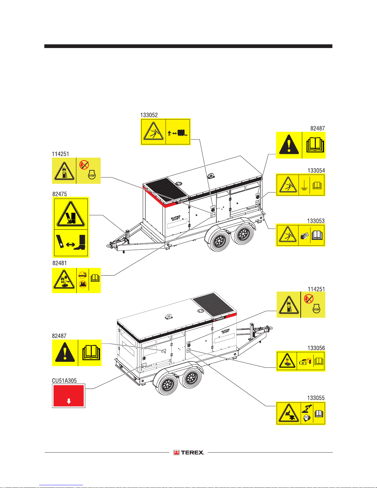
Safety Signs and Locations (Symbol Decals)
133052 A
114251 A
Operator's Manual
General Safety
82487 C
133054 A
82481 B
EMERGENCY
STOP
82475 D
133053 A
114251 A
82487 C
130059 A
Part No. 140435 T180 • T240 7
133055 A
Page 10
Operator's Manual First Edition • First Printing
Operation Safety
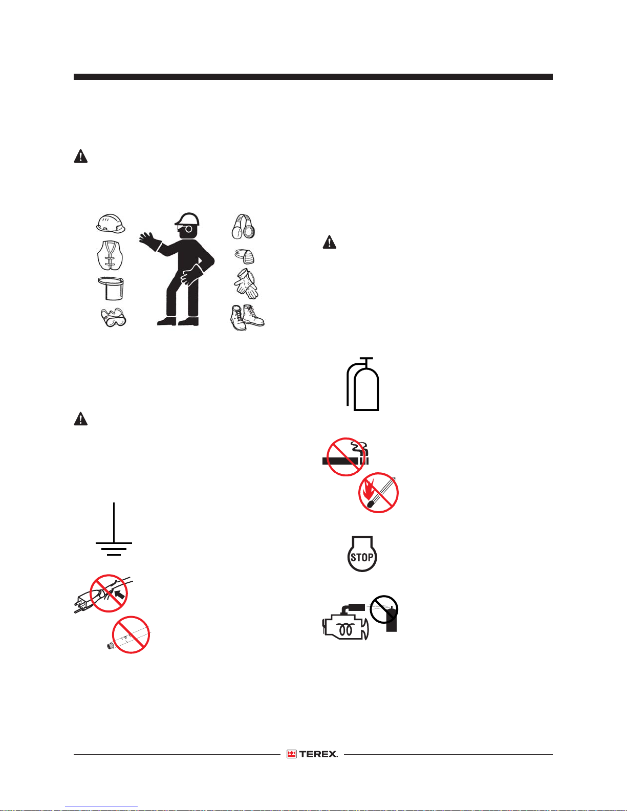
Personal Safety
Operators must comply with employer, job site and
governmental rules regarding the use of personal
protective equipment.
Use protective clothing and safety equipment such
as gloves, safety boots, safety hard hat, goggles,
ear protection, and dust mask when necessary.
Wear protective clothing that is snug and belted
where required.
Electrocution Hazards
This equipment contains high voltage circuits.
Contact with high voltage will result in death or
serious injury. Exercise extreme caution around
any electrical component while operating this unit.
Always ground the unit
according to local codes. A
grounding lug is provided for
your convenience. Improper
grounding can result in death or
serious injury.
Beware of cut or damaged power
cords and cables. Have a
qualified electrician replace any
damaged cords or cables
immediately.
Do not apply voltage to a terminal that is outside
the range specified for that terminal.
Do not operate with covers or panel removed.
Extreme caution must be taken when operating the
unit in wet or damp conditions.
Explosion and Fire Hazards
Explosion or fire can cause severe personal injury
or machine damage.
Prevent fires by keeping the generator and its
surrounding area clean.
Do not place flammable objects near the generator.
Always have a fire extinguisher
nearby. Be sure that the
extinguisher is properly
maintained and be familiar with
its use. Extinguishers rated ABC
by the NFPA are appropriate for
all applications.
Do not refuel while smoking or
when near open flames or
sparks.
Fuel is highly flammable and
should always be handled with
care.
Always stop the engine before
fueling. Fill the fuel tank
outdoors in a well ventilated
area.
Do not use ether or other high
energy starting aids on
machines equipped with a glow
plug or grid heater. Starting
fluids, which contain ether, can
cause an explosion that can
result in death or serious injury.
Refer to the engine
manufacturer’s operating
instructions.
8 T180 • T240 Part No. 140435
Page 11
First Edition • First Printing
Operator's Manual
Operation Safety
Do not refuel while the engine is still hot. Allow the
engine to cool down for several minutes before
refueling.
Do not spill fuel inside the engine compartment. If
fuel has leaked, wipe it up and have the leak
repaired before the next use.
Toxic Gas and Burn Hazard
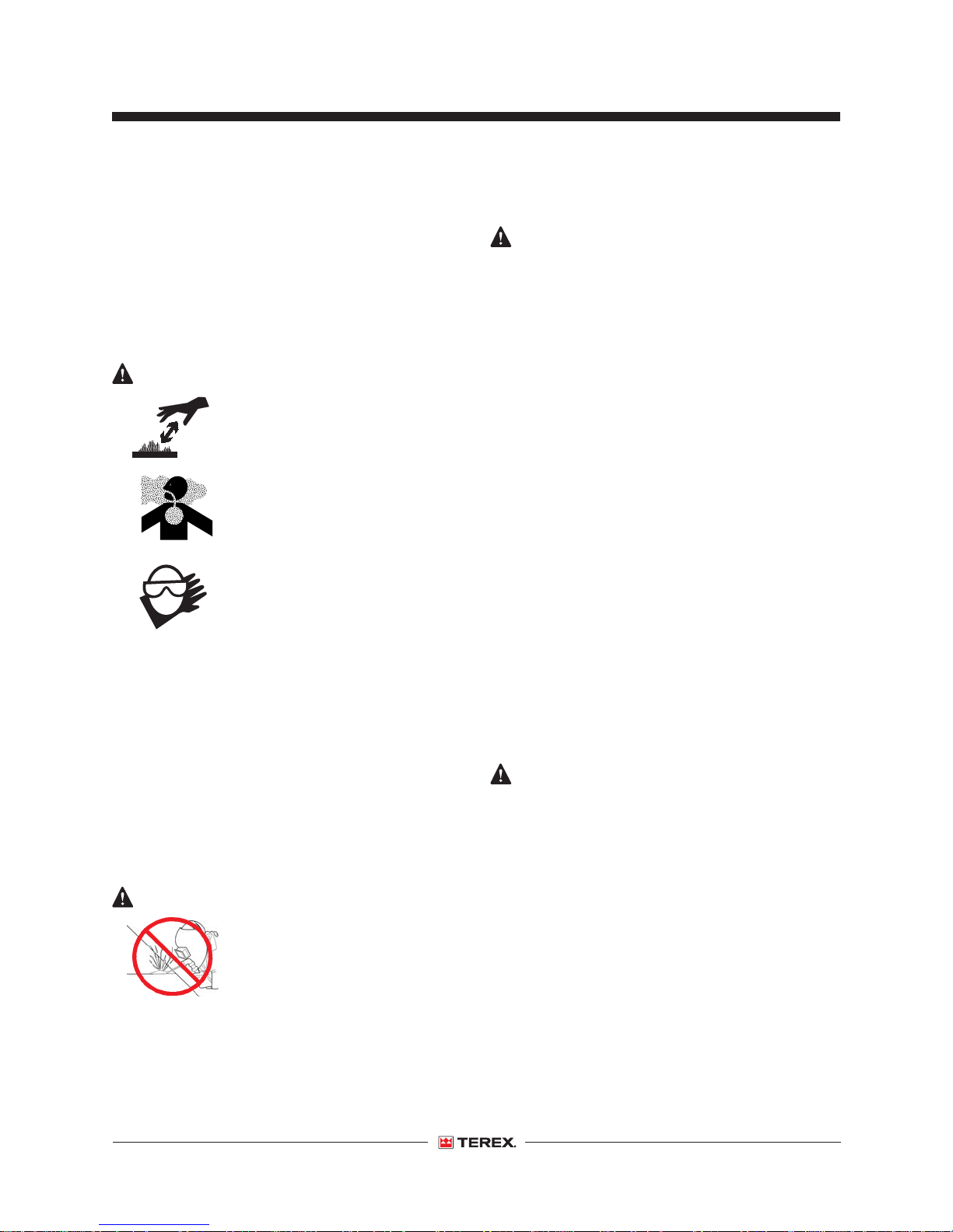
The exhaust manifold, tail pipe
and other parts of the engine get
hot. Do not touch hot parts.
Hot exhaust can contain toxic
gases like carbon monoxide
that, if inhaled, will result in
death or serious injury. Do not
breath exhaust gas.
Use protective gloves when
handling hot parts.
Never remove the radiator cap
while the engine is running or
while the engine is hot.
Do not use indoors unless the
area is properly ventilated or an
exhaust scrubber is used.
Bodily Injury and Component
Damage Hazards
Loose jackets, shirts, sleeves, jewelry and neck
ties should not be worn while working on or
operating the generator.
Never remove the fan guards while the unit is
operating. Turn the generator off before removing
the fan guards or other protective devices from
the generator to gain temporary access for
maintenance. Replace the fan guards and other
protective devices immediately after servicing.
Keep your hands away from moving parts,
particularly clear of the radiator fan and alternator
belts when the engine is running.
Do not shut the unit down with the main generator
circuit breaker in the on position. Shutting the unit
down with the breaker in the on position can cause
damage to the generator and/or connected
apparatus.
Do not change the position of the voltage selector
switch while the generator is running. This will
result in immediate damage to the switch, the
generator or the conected equipment. It may result
in serious injury to the operator.
Check the exhaust system
regularly for leaks and ensure
that the exhaust manifolds are
secure and not warped. Make
sure that the machine is well
ventilated.
Welding Hazard
Do not weld on any structural
member. Unauthorized welding
or repair procedure can result in
structural failure or personal
injury and will void the warranty.
Part No. 140435 T180 • T240 9
Improper Use Hazard
When leaving the generator set unattended,
secure the machine from unauthorized use.
Unauthorized personnel may attempt to operate
the machine without proper instructions, creating
an unsafe condition.
Page 12
Operator's Manual First Edition • First Printing
Operation Safety
Transport and Lifting Hazard
Be careful when lifting. Never suspend any other
equipment from the shipping tie-downs.
Use the lifting eye for lifting the trailer (with cabinet).
Make sure that the tie-downs at the bottom of the
trailer are released prior to lifting. Refer to Transport
and Towing section for recommended tie-down
procedures.
Never climb on top of the cabinet.
Always use the proper trailer hitch and safety
chains. Obey all local or state D.O.T. laws when
transporting the generator set.
Failure to properly secure the generator set to the
transport vehicle may result in death or serious
injury.
Towing Hazards
Driving a vehicle/trailer combination is different
from driving a vehicle alone. Read, understand and
obey all of your tow vehicle manufacturer’s
recommendations, warning and instructions before
towing the trailer.
Increase the distance between your vehicle and
the vehicle in front of you to twice the normal
following distance when towing a trailer. Allow
more following distance in adverse weather
condition.
Always slow down for curves, wet roads and
down grades.
Heavy winds, excessive speed, load shifting or
passing vehicles can cause the trailer to sway
while driving. If this occurs, do not step on the
brake, speed up or turn the steering wheel.
Applying the brakes or turning the steering wheel
can cause the vehicle to jackknife. Release the
gas pedal and keep the steering wheel straight.
When passing other vehicles, be sure to leave
enough room for the extra length of the trailer.
Check for tire inflation. Do not over or under inflate
the tires. Tire pressure goes up while driving. Allow
the tires to cool down to get the accurate tire
pressure. Refer to the trailer VIN decal for proper
tire inflation.
Stay clear of traffic when starting or checking the
unit along the road.
Check the fuel tank, oil pan, fuel lines, oil lines and
drain plugs for leaks that would spill fuel or oil on
the road.
Check fasteners and mounting brackets
periodically to insure that all are tight and nothing is
in danger of falling off during transit.
Always use the proper trailer hitch and safety
chains. Obey all local or state D.O.T. laws when
towing the generator set.
Failure to properly secure the trailer to the towing
vehicle may result in death or serious injury.
Observe the posted speed limits for trailers.
10 T180 • T240 Part No. 140435
Page 13
First Edition • First Printing
Operator's Manual
Operation Safety
Battery Safety
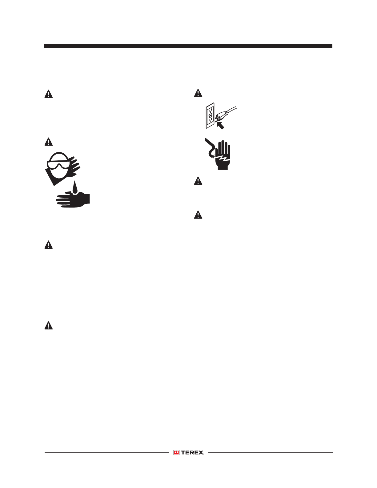
Lead acid batteries can be dangerous. The acid in
the battery can cause severe skin and eye burns.
The hydrogen gas emitted during charging can
explode if an arc or flame is present.
Burn Hazards
Do not remove the vent caps
when charging the batteries.
Always wear protective clothing
and eye wear when working with
batteries. If acid gets on your
skin or eyes, immediately flush
under running water and obtain
medical attention.
Do not expose the batteries or the charger to water
or rain during charging.
Explosion and Fire Hazards
Keep sparks, flames and lighted tobacco away
from batteries. Batteries emit an explosive gas.
Do not contact the battery terminals or the cable
clamps with tools that may cause sparks.
Disconnect the negative terminal of the battery
when working on the engine or other parts to
prevent accidental arcing.
Component Damage
Hazards
Electrocution/Burn Hazards
If using a charger, connect the
battery charger to a grounded,
AC 3-wire electrical outlet only.
Avoid electrical shock from
contact with battery terminals.
Remove all rings, watches and
other jewelry.
Lifting Hazard
Use the appropriate number of people and proper
lifting techniques when lifting batteries.
Lockout After Each Use
1 Select a safe parking location-firm level surface,
clear of obstruction and traffic.
2 Turn all generator breakers to the off position.
3 Allow the engine to run for 5 minutes under no
load until the coolant temperature gauge reads
approximately 175°F (79.4°C) as a cool down
cycle.
4 Push the Cascade controller off button to stop
the engine.
5 Move the on/off toggle switch to the off position.
5 Chock the wheels.
6 Lock the doors.
Do not use any battery charger greater than 24V to
charge the batteries.
Part No. 140435 T180 • T240 11
Page 14
Operator's Manual First Edition • First Printing
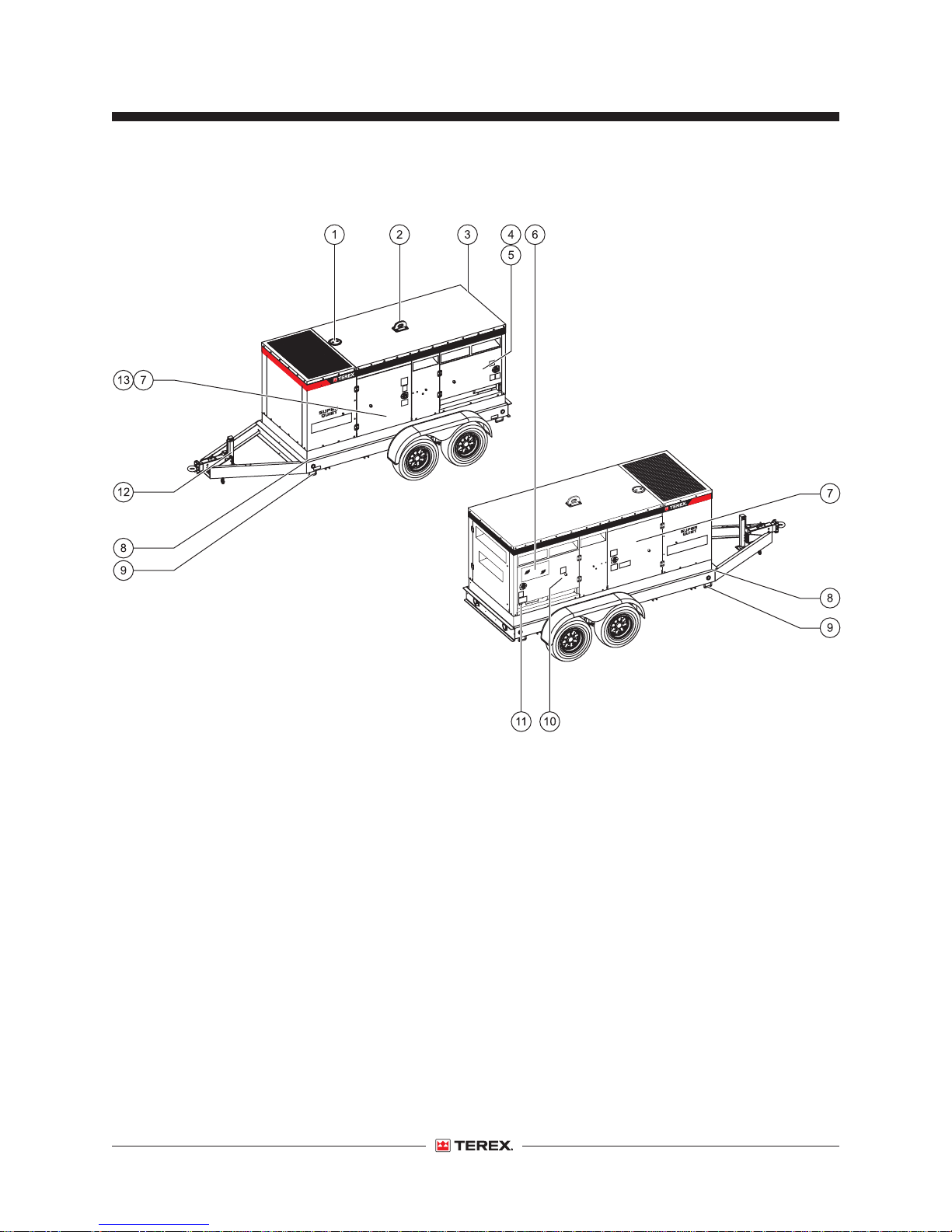
Legend
1 Radiator fill
2 Lifting eye
3 Generator compartment
4 Three-phase door
5 Distribution panel (behind door)
6 Main control panel
7 Engine (behind door)
8 Tie-down points (generator set)
9 Tie-down points (trailer)
12 T180 • T240 Part No. 140435
10 Document holder (back of door)
11 Red Emergency Stop button
12 Tongue jack
13 Battery compartment
Page 15
First Edition • First Printing
Operator's Manual
Legend
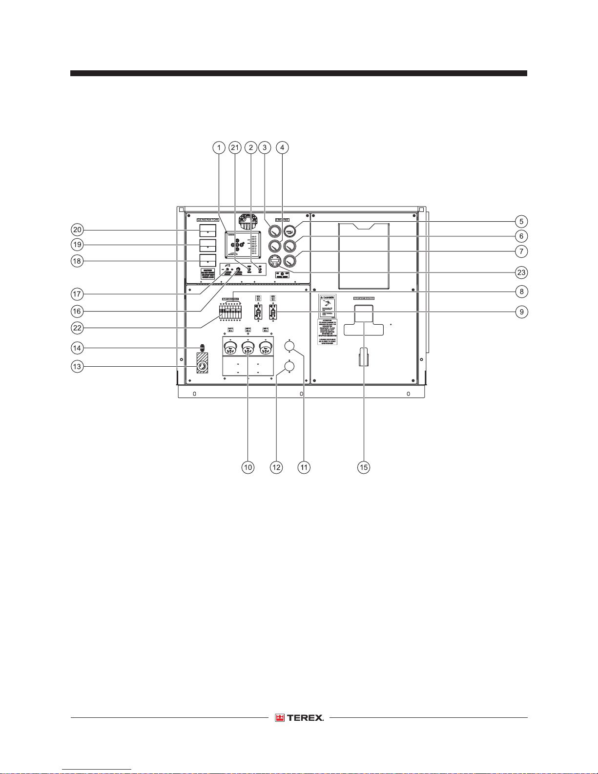
Main Control Panel - Cascade Controller
1 Cascade controller
2 On/off toggle switch
3 Engine voltmeter
4 Engine oil pressure gauge
5 Engine hour meter
6 Engine coolant gauge
7 Engine fuel gauge
8 Single phase breakers
9 Receptacle - 120V, 20 Amp GFI
10 Receptacle - 50 Amp, twist lock
11 Receptacle - Battery charger (optional)
12 Receptacle - Block heater (optional)
Part No. 140435 T180 • T240 13
13 Emergency Stop button
14 Remote start switch
15 Shunt trip breaker
16 Control breaker
17 Voltage adjustment switch
18 Generator ammeter
19 Generator frequency meter
20 Generator voltmeter
21 Idle/run switch
22 Single phase main breaker
23 ECU fault code reader
Page 16
Operator's Manual First Edition • First Printing
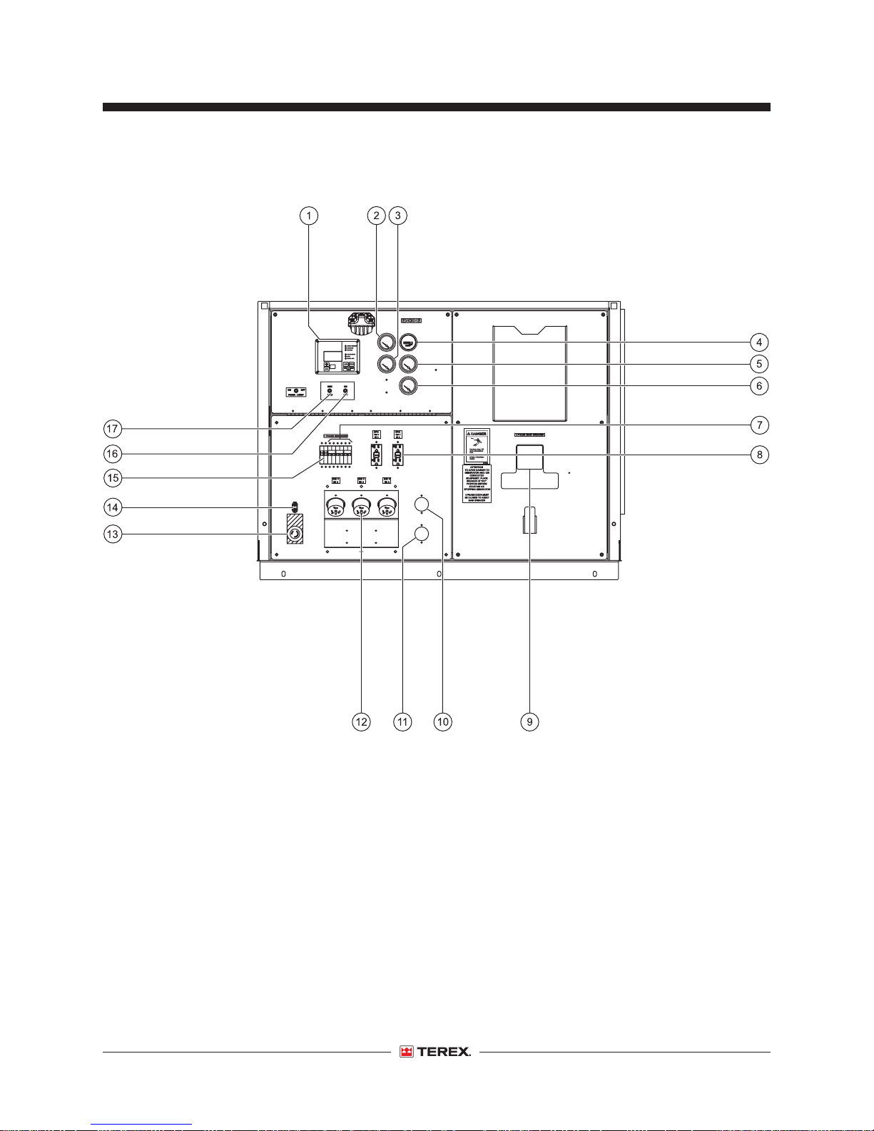
Legend
Main Control Panel - Cummins Controller
1 Cummins controller
2 Engine voltmeter
3 Engine oil pressure gauge
4 Engine hour meter
5 Engine coolant gauge
6 Engine fuel gauge
7 Single phase breakers
8 Receptacle - 120V, 20 Amp GFI
9 Shunt trip breaker
14 T180 • T240 Part No. 140435
10 Receptacle - Battery charger (optional)
11 Receptacle - Block heater (optional)
12 Receptacle - 50 Amp, twist lock
13 Emergency Stop button
14 Remote start switch
15 Single phase main breaker
16 Control breaker
17 Voltage adjustment switch
Page 17
First Edition • First Printing
Operator's Manual
Legend
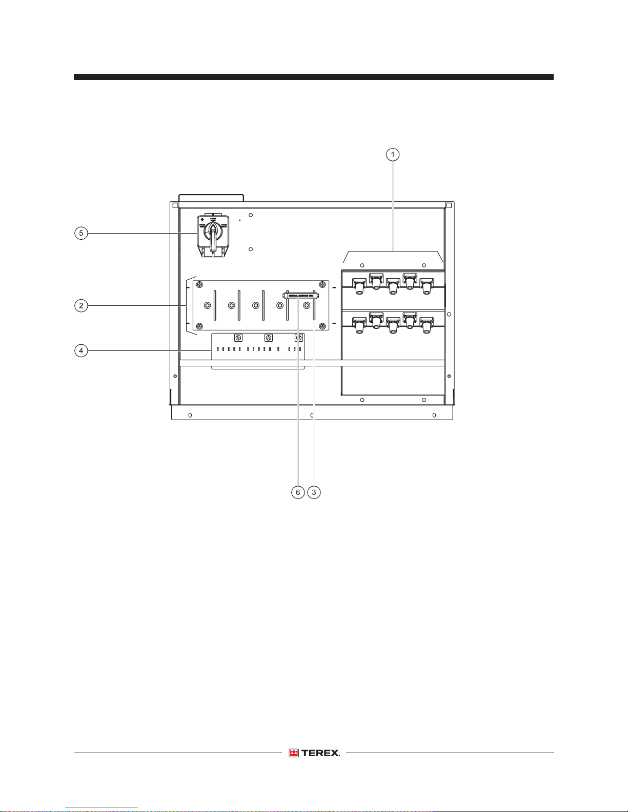
Distribution Panel
1 Cam-lock panel (optional)
2 Distribution panel
3 Distribution lug
4 3-Phase distribution panel diagram
5 Voltage selector switch
6 Neutral bonding bar
Part No. 140435 T180 • T240 15
Page 18
Operator's Manual First Edition • First Printing
Inspections
Pre-operation Inspection
Fundamentals
It is the responsibility of the operator to perform a
pre-operation inspection and routine maintenance.
The pre-operation inspection is a visual inspection
Do Not Operate Unless:
You learn and practice the principles of safe
generator operation contained in this operator's
manual.
1 Avoid hazardous situations.
2 Always perform a pre-operation
inspection.
Know and understand the pre-operation
inspection before going on to the next
section.
3 Follow setup instructions.
4 Follow operating, and transport and towing
instructions.
5 Only use the generator as it was intended.
performed by the operator prior to each work shift.
The inspection is designed to discover if anything
is apparently wrong with the generator set before
putting it in service.
The pre-operation inspection also serves to
determine if routine maintenance procedures are
required. Only routine maintenance items specified
in this manual may be performed by the operator.
Refer to the list on the next page and check each
of the items.
If damage or any unauthorized variation from
factory delivered condition is discovered, the
generator set must be tagged and removed from
service.
Repairs to the generator set may only be made by
a qualified service technician, according to the
manufacturer's specifications. After repairs are
completed, the operator must perform a
pre-operation inspection again before putting the
generator into service.
16 T180 • T240 Part No. 140435
Scheduled maintenance inspections shall be
performed by qualified service technicians,
according to the manufacturer's specifications.
Page 19

First Edition • First Printing
Operator's Manual
Inspections
Pre-operation Inspection
o
Be sure that the operator’s manuals are
complete, legible and in the storage container
located at the back of the control panel access
door.
o
Be sure that all decals are legible and in place.
See Inspection section.
o
Check the engine fuel level.
o
Check for fuel leaks.
o
Check for engine oil leaks and proper oil level.
Add oil if needed. See Maintenance section.
o
Check for engine coolant leaks and proper level
of coolant. Add coolant if needed. See
Maintenance section.
o
Check the fuel/water separator for water in the
fuel system.
Check the following components or areas for
damage, improperly installed or missing parts and
unauthorized modifications:
o
Electrical components, wiring and
electrical cables
o
Nuts, bolts and other fasteners
Check entire generator for:
o
Cracks in welds or structural components
o
Excessive rust, corrosion or oxidation
o
Be sure that all structural and other critical
components are present and all associated
fasteners are in place and properly tightened.
Part No. 140435 T180 • T240 17
Page 20
Operator's Manual First Edition • First Printing
Inspections
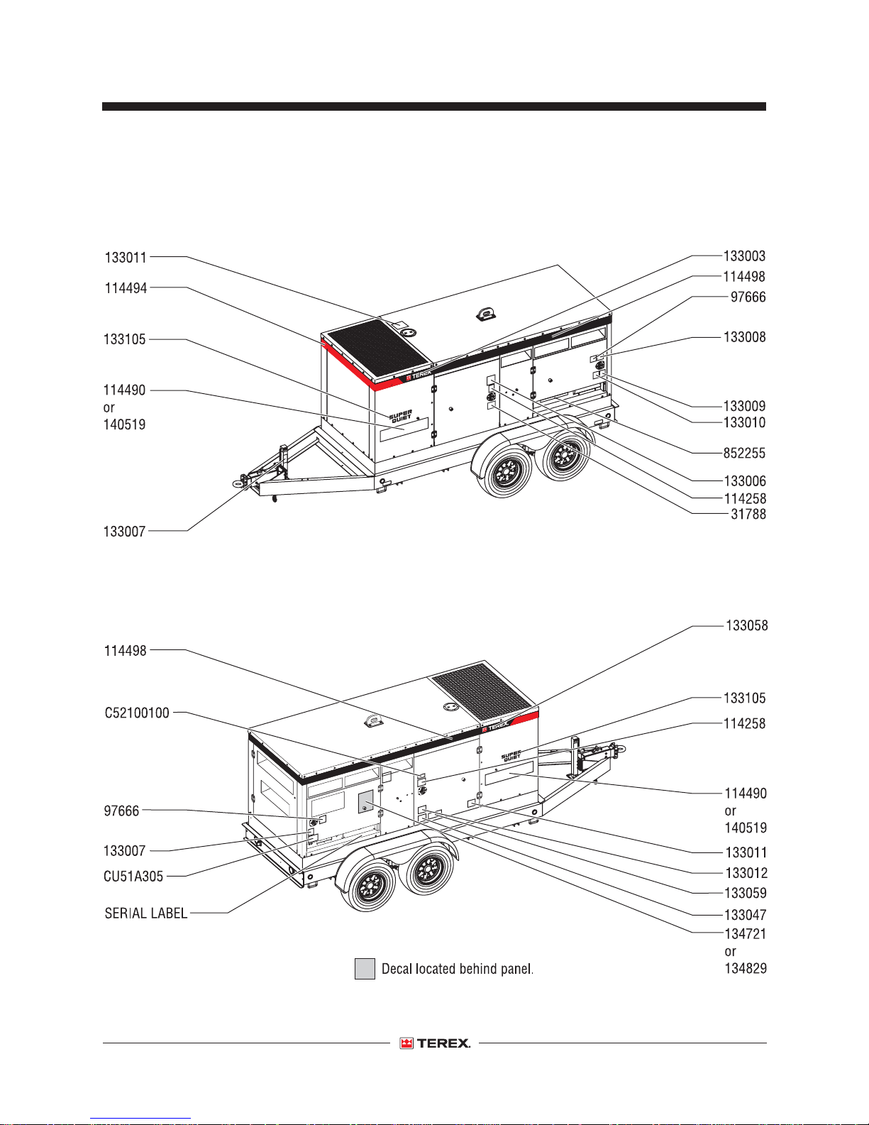
Inspection for decals with words
Determine whether the decals on your machine
have words or symbols. Use the appropriate
inspection to verify that all decals are legible and in
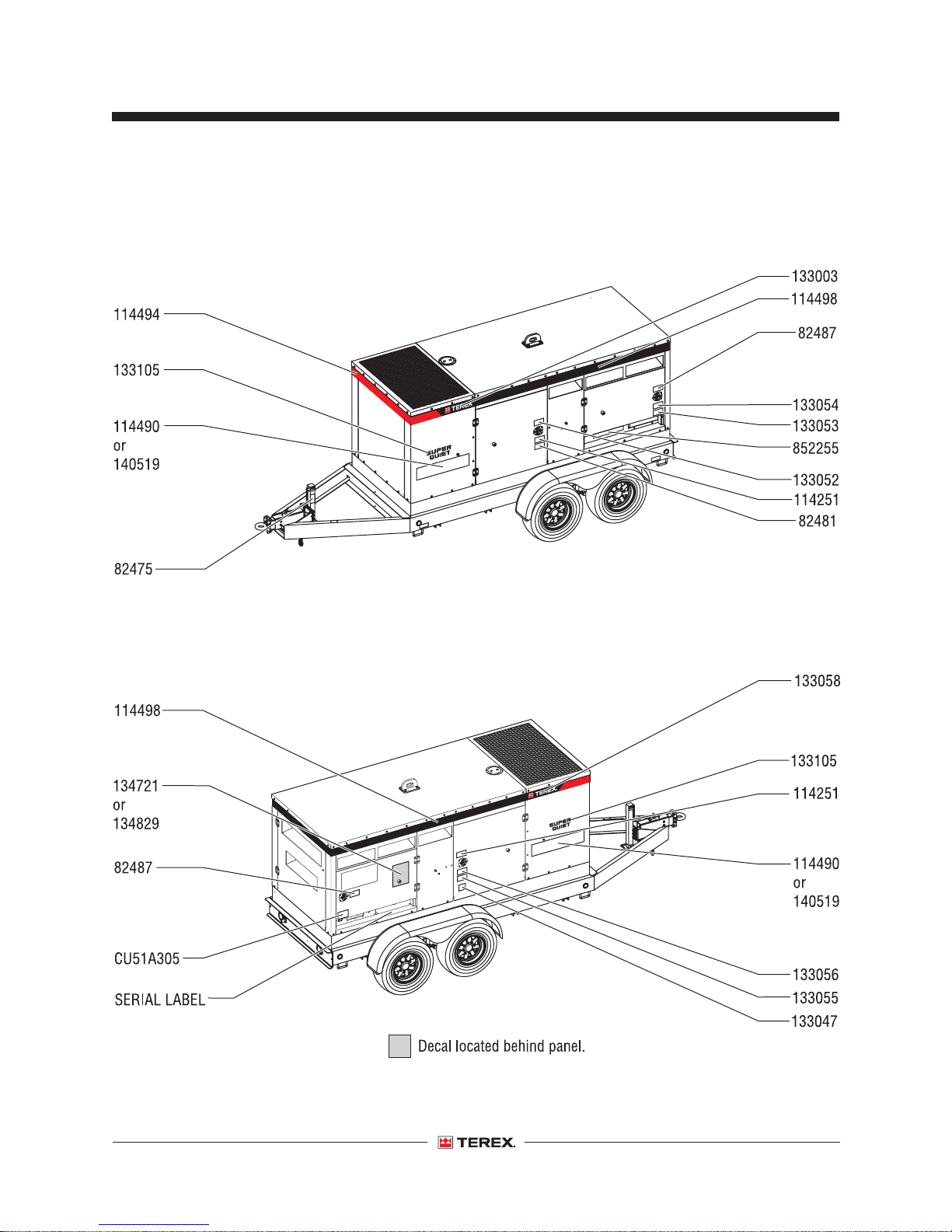
place.
Below is a numerical list with quantities and
description.
Part No. Description Quantity
31788 Warning - Battery Safety 1
97666 Warning - Read the Manual 2
114258 Danger - No Smoking 2
114494 Red Stripe - 45 inches / 1.1 m 1
114498 Black Stripe - 140 inches / 3.5 m 2
133003 Cosmetic - Terex, left panel 1
133006 Danger - Electrocution Hazard 1
133007 Warning - Foot Crushing Hazard 1
133008 Instructions - Do not open
3-Phase Door 1
133009 Danger - Electrocution Hazard,
Lockout/Tagout 1
133010 Warning - Electrocution Hazard,
Ground Unit 1
133011 Notice - Radiator Fill 1
133012 Danger - Burn/Carbon
Monoxide Hazard 1
Part No. Description Quantity
133047 Label - Number 2 Diesel Fuel 1
133058 Cosmetic - Terex, right panel 1
133059 Warning - Engine Explosion 1
133074 Cosmetic - T180 2
133105 Cosmetic - Super Quiet 2
134721 Label - Operating Instruction 1
134721 Instructions - Cascade Controller 1
134829 Instructions - Cummins Controller 1
140519 Cosmetic - T240 2
852255 Label - 3-Phase Distribution Panel 1
C52100100 Label - California Proposition 65 1
CU51A305 Label - Emegency Stop 1
18 T180 • T240 Part No. 140435
Page 21
First Edition • First Printing
Distribution Panel Side
Operator's Manual
Inspections
Control Panel Side
Part No. 140435 T180 • T240 19
Page 22
Operator's Manual First Edition • First Printing
Inspections
Inspection for decals with
symbols
Determine whether the decals on your machine
have words or symbols. Use the appropriate
inspection to verify that all decals are legible and in
place.
Below is a numerical list with quantities and
description.
Part No. Description Quantity
82475 Label - Foot Crushing Hazard 1
82481 Label - Battery/Charger Safety 1
82487 Label - Read the Manual 2
114251 Label - Explosion Hazard 2
114494 Red Stripe - 45 inches / 1.1 m 1
114498 Black Stripe - 140 inches / 3.5 m 2
133003 Cosmetic - Terex, left Panel 1
133047 Label - Number 2 Diesel 1
133052 Label - Electrocution Hazard,
High Voltage 1
133053 Label - Electrocution Hazard,
Lockout/Tagout 1
133054 Label - Electrocution Hazard,
Ground Unit Properly 1
Part No. Description Quantity
133055 Label - Burn / Carbon
Monoxide Hazard 1
133056 Label - Engine Explosion
Hazard Do Not Use
Engine Starting Aid 1
133058 Cosmetic - Terex, right Panel 1
133074 Cosmetic - T180 2
133105 Cosmetic - Super Quiet 2
134721 Instruction- Cascade Controller 1
134829 Instruction- Cummins Controller 1
140519 Cosmetic - T240 2
852255 Label - 3-Phase Distribution Panel 1
CU51A305 Label - Emegency Stop 1
20 T180 • T240 Part No. 140435
Page 23
First Edition • First Printing
Distribution Panel Side
Operator's Manual
Inspections
Control Panel Side
Part No. 140435 T180 • T240 21
Page 24
Operator's Manual First Edition • First Printing
Setup
Fundamentals
The setup section provides instructions for setting
up the generator set in the work place so it can be
used safely.
It is the operator's responsibility to follow all the
safety rules and instructions in the operator's
manual.
Do Not Operate Unless:
Move the generator set to the desired location with
You learn and practice the principles of safe
generator operation contained in this operator's
manual.
1 Avoid hazardous situations.
2 Always perform a pre-operation inspection.
3 Follow the setup instructions.
Know and understand the setup
instructions before going on to the next
section.
4 Follow the operating, transport and towing
instructions.
5 Only use the generator set as it was intended.
the following in mind:
• The spot where the generator set is positioned
should be relatively level.
• The location selected should be centrally
located to the equipment requiring the loads to
minimize voltage drop in the power cord.
• Locate the machine so the power cords can be
routed without crossing roads and access
routes.
• Locate the machine where the engine will get
proper ventillation. Avoid locations where fumes
can enter a building.
• Do not place the machine beside a building wall
that would reflect and intensify noise.
22 T180 • T240 Part No. 140435
Page 25
First Edition • First Printing
Operator's Manual
Setup
Unhitching from the towing vehicle:
1 Position the generator set in the desired
location.
Note: If the axle is sloped downhill, turn the
generator set so that the axle is level.
2 Chock the wheels.
3 Unhook the safety chains and running lights.
4 Pull the spring pin on the leveling jack and slide
the jack down.
5 Release the hitch pin and raise the tongue off
the towing vehicle.
6 Level the generator set with the tongue jack.
Note: The wheels must be properly chocked if the
generator is on unlevel ground. Do not operate the
generator set until it has been properly secured.
Preparing to start the generator set:
1 Check the coolant level in the radiator. Add
coolant if necessary. See maintenance section.
4 Check the fuel/water separator for water in the
fuel system. Drain water from the separator if
necessary.
5 Check the fuel level in the fuel tank. Add as
required. Make sure that the fuel tank vent is
open and not clogged.
Use number 2 diesel fuel only.
6 Verify that the generator main circuit breaker is
in the off position.
7 Connect the grounding lug in the distribution
panel to a mechanical earth ground as per your
local electrical code.
Note: Always follow the local code for grounding.
Make sure that the generator set is properly
grounded.
The generator set produces voltages that may
cause severe shock or death. Only qualified
electricians should perform electrical work.
Note: If adding coolant, only use a 50/50 mixture of
antifreeze and water. Refer to your engine
manufacturer’s maintenance manual for specific
antifreeze information.
2 Check the oil level in the engine crankcase. Add
oil if necessary. See Maintenance section.
Note: Use class API, CC, or CD grade engine oil.
Refer to the engine manufacturer’s manual for
viscosity and quantity.
3 If the battery is not a maintenance free battery,
check the electrolyte level. Add distilled water if
necessary.
Part No. 140435 T180 • T240 23
Page 26
Operator's Manual First Edition • First Printing
Operating Instructions
Fundamentals
The Operating Instructions section provides
instructions for the general operation of the unit.
For more in-depth information on operating the unit,
refer to the generator and engine manufacturer’s
operating instructions.
Do Not Operate Unless:
You learn and practice the principles of safe
generator operation contained in this operator's
manual.
1 Avoid hazardous situations.
2 Always perform a pre-operation inspection.
3 Follow the setup instructions.
It is the operator's responsibility to follow all the
safety rules and instructions in the operator's
manual.
4 Follow the operating, transport and towing
instructions.
Know and understand the operating,
transport and towing instructions
before going on to the next section.
5 Only use the generator set as it was intended.
24 T180 • T240 Part No. 140435
Page 27
First Edition • First Printing
Operator's Manual
Operating Instructions
Starting the engine / generator set
1 Follow the setup procedure.
2 Make sure that the circuit breakers, located on
the control panel, are in the off position.
3 At the distribution panel side of the generator
set, locate the voltage selector switch and set it
to the desired range.
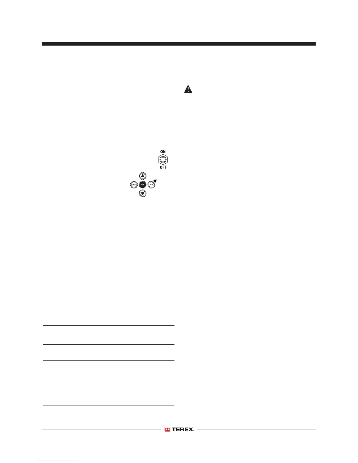
4 At the control panel side, locate the
toggle switch. Switch it to the on
position.
5 Press the manual button
(MAN) on the Cascade
controller to start the
generator.
The generator will make three attempts at starting
before it must be reset with the switch.
Note: The installation and operations manual for the
Cascade CD101 auto-start controller is available at
www.fwmurphy.com.
6 Allow the generator to warm up for 5 minutes
after starting.
Listen for unusual sounds or excess vibrations that
could signal problems and require immediate
shutdown of the unit. If unusual sounds are
detected, shut the unit down and contact Terex
Sevice at 1-800-433-3026.
7 Once the engine is running smoothly, monitor
the gauges as stated in the table below.
Never change the position of the voltage
selector switch while the generator is running. This
will result in immediate damage to the switch, the
generator, or the connected equipment. It may
result in serious injury to the operator.
Loading instructions
1 Shut down the generator set.
2 Press the off button on the Cascade control
panel. Move the on/off toggle switch to the off
position.
3 Connect the desired electrical apparatus to the
generator set.
4 Restart the engine and monitor the gauges as
tabulated in step 7 in starting the generator set
on this page.
5 Turn the required circuit breakers to the on
position.
6 Monitor the AC ammeter. If the needle deflects
severely to the right and stays there,
immediately turn the required generator circuit
breakers to the off position.
Note: Severe deflection of the ammeter indicates a
wiring problem or an overload problem. Continued
operation under this condition will cause damage
to the generator and/or connected apparatus.
The needle on the ammeter will deflect to the right
temporarily and then return to a normal reading if
the unit is operating properly.
Oil Pressure equal to or greater than 30 psi
Coolant Temperature 170-225 °F / 77-93 °C
DC Voltmeter 13-15 volts
(indicates that the diesel engine’s alternator is charging)
AC Voltmeter reflects the proper voltage
selected
Refer to potentiometer (Voltage Adjustment ) on page 27.
AC Ammeter 0 (main breaker in off position)
Note: The ammeter will register the appropriate reading
once a load is applied to the generator.
Part No. 140435 T180 • T240 25
Page 28
Operator's Manual First Edition • First Printing
Operating Instructions
Voltage Selector Switch Operation
The voltage selector switch can affect the singlephase receptacles provided on the unit. The
indicated voltages should be checked after
selecting the setting of the switch. The Y voltage
configuration of 480 and 240 will produce a voltage
of 139 on the GFI receptacles.
This generator set produces voltages that can
cause severe shock or death. Only qualified
electricians should perform electrical work.
Exercise extreme caution around any electrical
component when operating this unit.
Never operate the voltage selector switch while
the generator is running. This will result in
immediate damage to the switch, the generator or
the connected equipment and may result in serious
injury to the operator.
Note: Always make sure that the voltage selector
switch has been set to the desired range before
starting the generator set.
The voltage selector switch for all the generators
has three positions marked 480 / 277 - 3 phase,
240 / 139 - 3 phase, and 240 / 120 - 1 phase. Each
position gives a different output to the three-phase
distribution lugs (designated as L1, L2, L3 and N)
located on the distribution panel.
480 / 277, 3 - phase position Output
(Hi Wye configuration)
Line - to - Line 480 VAC / 3P
(L1 to L2,/ L2 to L3 / L1 to L3)
Line - to - Neutral 277 VAC / 1P
(L1, L2 or L3 to N)
240 / 139, 3 - phase position
(Lo Wye configuration) Output
Line - to - Line 240 VAC / 3P
(L1 to L2,/ L2 to L3 / L1 to L3)
Line - to - Neutral 139 VAC / 1P
(L1, L2 or L3 to N)
240 single phase
(Zig Zag configuration - L2 not used) Output
Line - to - Line (L1 to L3) 240 VAC / 1P
Line - to - Neutral (L1 or L3 to N) 120 VAC 1P
Note: The Hi Wye and the Lo Wye configurations
can be adjusted by using the voltage adjustment.
Once the required voltages are known, the
combination of the proper switch position and
voltage adjustment potentiometer allows for fine
tuning the voltage to the exact needs of the
application.
When the proper voltage selector switch position is
selected, lock the switch in that position. This
prevents the switch from being moved while the
unit is operating or by unauthorized personnel.
Damage to the unit and any connected equipment
will be avoided.
26 T180 • T240 Part No. 140435
Page 29
First Edition • First Printing
Operator's Manual
Operating Instructions
Do not operate the unit unless the voltage has
been checked at the receptacles. If you have any
questions, call Terex Service at 1-800-433-3026.
Installation and any work performed on this unit
should be done only by a qualified electrician.
Potentiometer (Voltage adjustment)
The potentiometer is set at the factory. However, if
the voltage reading on the voltmeter is not as
desired, follow the procedure below to make the
necessary adjustments.
1 With the unit running under no load, observe the
AC voltmeter.
2 Locate the voltage adjustment knob on the
control panel. To increase the voltage, turn the
knob to the right. To decrease the voltage, turn
the knob to the left.
3 Slowly turn the adjustment knob in the desired
direction while observing the AC voltage meter.
4 Stop when the desired voltage is reached.
The unit is now ready to load. If the desired voltage
cannot be reached, contact the Terex Service
Department at 1-800-433-3026.
For more information, refer to the Murphy Cascade
Controller Installation and Operations Manual p/n
00-02-0594 (Terex part number 833011) supplied
with the unit for configuration and operation.
Overcurrent Protection
The overcurrent protection relay is mounted behind
the control panel. It monitors the current draw to
protect the generator set. The trip setting is set at
the factory with the proper kW using a loadbank.
Note: Do not change the setting. Generator failure
can occur. Call Terex Service for wiring and
trouble shooting information.
Shut down Procedures
Never shut the unit down while under load. This
may cause serious injuries to the operator or
damage the generator.
Never shut the unit down with the main
generator circuit breaker in the on position. This
can cause damage to the generator and/or the
connected apparatus.
1 Turn all generator breakers to the off position.
2 Allow the engine to run for 5 minutes under no
load until the coolant temperature gauge reads
approximately 175°F (79.4°C) as a cool down
cycle.
3 Push the Cascade controller off button to stop
the engine.
4 Move the on/off toggle switch to the off position.
5 Lock the doors.
Part No. 140435 T180 • T240 27
Page 30
Operator's Manual First Edition • First Printing
Transport Instructions
Securing to truck or trailer for
transit
1 Close, latch and lock all doors.
2 Level the unit.
3 Inspect the entire machine for loose and
unsecured items.
Observe and Obey:
Terex Corporation provides this securement
information as a recommendation. Drivers are
solely responsible for making sure that the
generator set is properly secured and the
correct trailer is selected pursuant to US
Department of Transportation regulations, other
localized regulations and company policy.
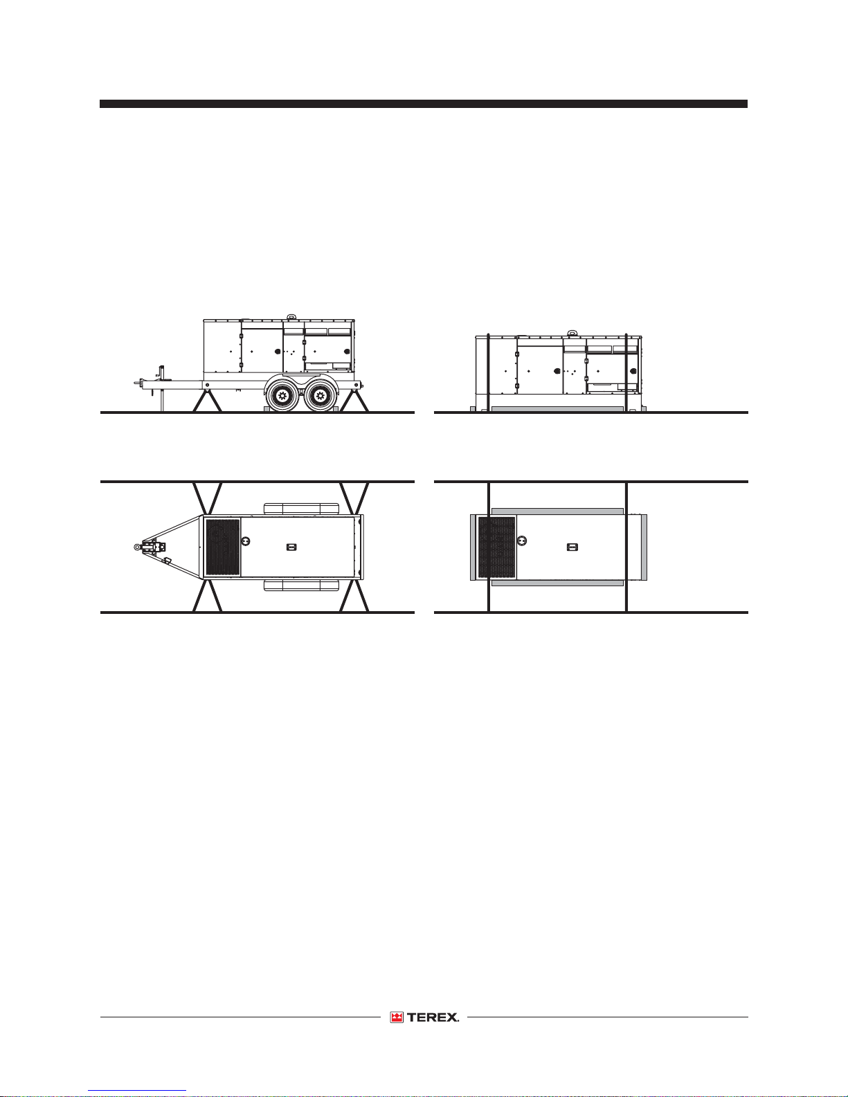
4 Place a chock on both sides of each axle
behind the wheels. Use the four tie-down points
on the machine for anchoring down to the
transport surface.
5 Use chain or straps of ample load capacity.
6 Adjust the rigging to prevent damage to the
chains.
Terex customers needing to containerize any
Terex product should source a qualified freight
forwarder with expertise in preparing, loading
and securing Terex equipment for international
shipment.
The transport vehicle must be parked on a level
surface.
The transport vehicle must be secured to
prevent rolling while the equipment is being
loaded.
Be sure the vehicle capacity, loading surfaces
and chains or straps are sufficient to withstand
the unit weight. See Specifications section for
unit weight.
28 T180 • T240 Part No. 140435
Page 31
First Edition • First Printing
Operator's Manual
Transport Instructions
Tie-down configuration for all models
Tie-down configuration, with trailer Tie-down configuration, no trailer
Part No. 140435 T180 • T240 29
Page 32
Operator's Manual First Edition • First Printing
Lifting Instructions
Lifting
1 Close, latch and lock all doors.
2 Inspect the entire machine for loose or
unsecured items.
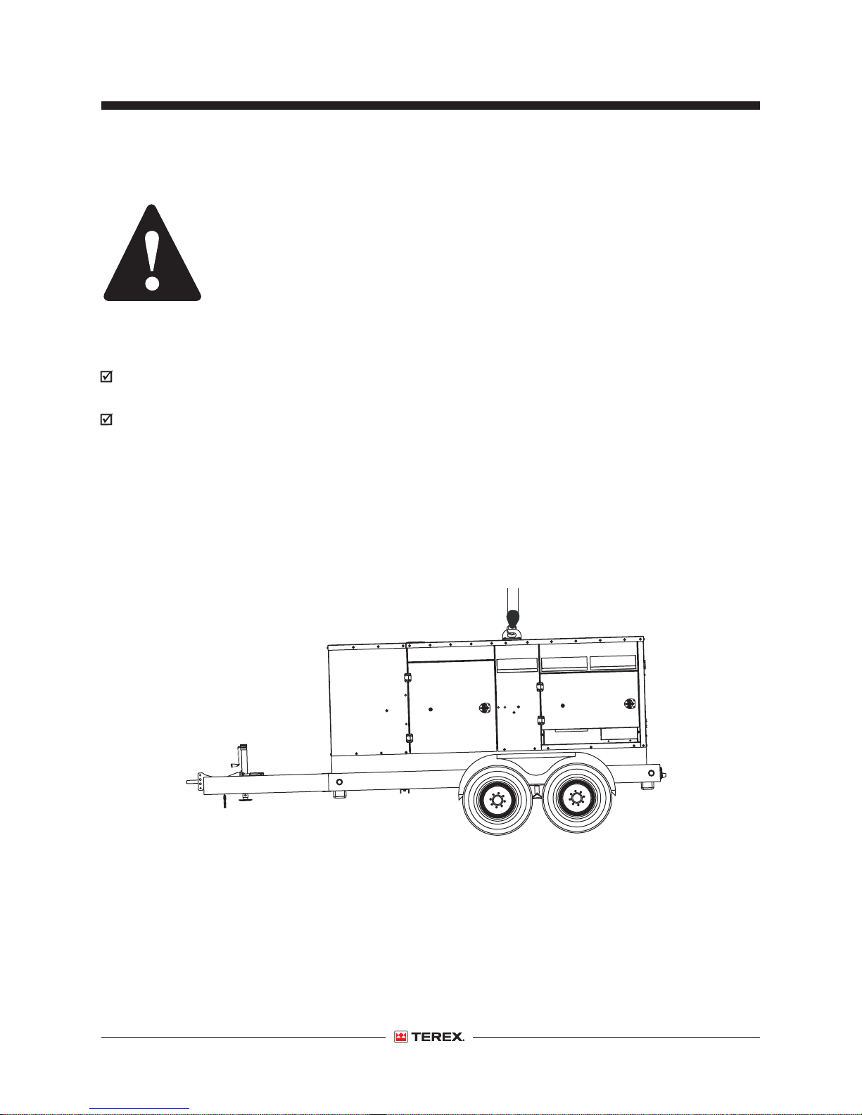
3 Use the lifting eye mounted on the top to lift the
machine.
Observe and Obey:
Only qualified riggers should rig and lift the
machine
Be sure the crane capacity, loading surfaces
and straps or lines are sufficient to withstand
the machine weight. See Specifications section
for unit weight.
Note: Make sure that tie-downs at the bottom of
the trailer or cabinet are released prior to lifting.
Lifting configuration
30 T180 • T240 Part No. 140435
Page 33
First Edition • First Printing
Operator's Manual
Towing Instructions
All trailer-mounted Terex generator sets are
designed for highway and off the road towing
capabilites. Consult state and local transportation
codes before transporting the generator set.
Additionally, all state and local traffic laws take
precedence over the following instructions
whenever differences arise between them.
Observe and Obey:
Hitching
Make sure that the hitch is sufficient to tow the
generator set.
Make sure that the hitch is properly attached to
the tow vehicle.
Make sure that the safety chains are properly
attached.
Inspect the tires and make sure that all tires are
properly inflated. Refer to the trailer VIN decal
for proper cold tire inflation.
Make sure that all lights are connected and
working.
Towing
Do not exceed 60 mph / 97 km/h.
Check connections and tire pressure at each
stop.
Slow down for hazardous conditions.
Note: Make sure the towing vehicle is of adequate
size to both tow and stop the unit.
1 Disconnect all wiring and cabling (including the
ground wire) from the generator set.
2 Close, latch and lock all access doors.
3 With the leveling jack, raise the trailer hitch to an
adequate height so that the generator can be
securely attached to the towing vehicle.
4 Secure the coupler to the vehicle and attach the
safety chains. Attach the “breakaway” chain on
the surge brake and the electrical coupler
(if equipped).
Always use the proper trailer hitch and safety
chains. Obey all local or state D.O.T. laws when
towing a generator.
Failure to properly secure the trailer to the
towing vehicle may result in death or serious injury.
5 Retract the front leveling jack into its stowed
position.
6 Check the tires for proper inflation and verify lug
nuts are tight. See Maintenance section.
Allow extra distance for following and passing
other vehicles.
Part No. 140435 T180 • T240 31
7 If equipped with towing light, connect the
electrical coupler to the towing vehicle.
8 Inspect all connections at each stop.
Observe the posted speed limits for trailer.
Generally, do not exceed 60 mph on paved roads
and 10 mph on unpaved roads.
Note: Exceeding these recommended speeds can
cause severe damage to the unit. Damage caused
by these unsafe practices will void the
manufacturer’s warranty.
Page 34

Operator's Manual First Edition • First Printing
Towing Instructions
Towing Information
Use the checklist provided on the back cover of
this manual before towing and while on the road.
Inspect all connections at each stop.
Driving a vehicle/trailer combination is
different from driving a vehicle alone.
All tires must be properly inflated. Find the
recommended cold tire pressure on the tire
sidewall or trailer VIN decal. Do not overinflate the
tires. Tire pressures go up during driving. Checking
the tire pressure when the tires are warm will give
you an inaccurate pressure and reading.
Increase the distance between your vehicle and the
vehicle in front of you to twice the normal following
distance when towing a trailer. Allow more following
distance in adverse weather.
Slow down for downgrades and shift your
transmission into a lower gear.
Slow down for curves, hazardous road conditions,
freeway exits, and when driving in adverse
weather.
When passing other vehicles, be sure to leave
enough room for the extra length of the trailer. You
will need to go much farther beyond the passed
vehicle before you can return to your lane.
Avoid sudden movements when turning.
Heavy winds, excessive speed, load shifting or
passing vehicles can cause the trailer to sway
while driving. If this occurs, do not brake, speed up
or turn the steering wheel. Turning the steering
wheel or applying the brakes can cause the vehicle
and trailer to jackknife. Let up on the gas pedal and
keep the steering wheel straight.
If the vehicle and/or trailer travels off the paved
road, hold the steering wheel firmly and let up on
the gas pedal. Do not apply the brakes. Do not turn
sharply. Slow down to under 25 mph /
40 km/h. Gradually turn the steering wheel to get
back on the road. Proceed with caution when
entering traffic.
32 T180 • T240 Part No. 140435
Page 35
First Edition • First Printing
Observe and Obey:
Only routine maintenance items specified in this
manual shall be performed by the operator.
Scheduled maintenance inspections shall be
completed by qualified service technicians,
according to the manufacturer's specifications.
Use only Terex approved replacement parts.
Operator's Manual
Maintenance
Maintenance Symbols Legend
The following symbols have been used in this
manual to help communicate the intent of the
instructions. When one or more of the symbols
appear at the beginning of a maintenance
procedure, it conveys the meaning below.
Indicates that new parts will be required to
perform this procedure.
Indicates that a cold engine is required
before performing this procedure.
Part No. 140435 T180 • T240 33
Page 36
Operator's Manual First Edition • First Printing
Maintenance
Check the Batteries
Proper battery condition is essential to good engine
performance and operational safety. Improper fluid
levels or damaged cables and connections can
result in engine component damage and hazardous
conditions.
Electrocution/burn hazard. Contact with hot or
live circuits may result in death or serious injury.
Remove all rings, watches and other jewelry.
Bodily injury hazard. Batteries contain acid.
Avoid spilling or contacting battery acid. Neutralize
battery acid spills with baking soda and water.
1 Put on protective clothing and eye wear.
2 Be sure that the battery cable connections are
tight and free of corrosion.
3 Be sure that the battery hold-down bracket is in
place and secure.
4 Remove the battery vent caps.
5 Check the battery acid level. If needed, replenish
with distilled water to the bottom of the battery
fill tube. Do not overfill.
6 Install the vent caps.
Note: Adding terminal protectors and a corrosion
preventative sealant will help eliminate corrosion
on the battery terminals and cables.
Check the Engine Oil Level
Note: Check the oil level with the engine off.
1 Check the oil dipstick. Add oil as needed.
Refer to the engine manufacturer’s operating
instructions manual for more information regarding
engine oil recommendations.
Check the Engine Coolant Level
Maintaining the engine coolant at the proper level is
essential to engine service life. Improper coolant
level will affect the engine's cooling capability and
damage engine components. Daily checks will
allow the inspector to identify changes in coolant
level that might indicate cooling system problems.
Burn hazard. Beware of hot engine parts and
coolant. Contact with hot engine parts and/or
coolant may cause severe burns.
Adding coolant to a hot engine can damage
the casting. Allow the engine to cool down to below
120°F (50°C) before adding the coolant.
1 Allow the engine to cool down to below 120°F
(50°C).
2 Open the radiator cap.
3 Visually check the coolant level. Add fluid as
needed.
Result:The fluid level should be at the bottom of
the fill neck.
The engine manufacturer recommends using a 50/
50 mixture of good quality water and fully
formulated antifreeze.
Maintaining the proper engine oil level is essential
to good engine performance and service life.
Operating the machine with an improper oil level
can damage engine components.
34 T180 • T240 Part No. 140435
Antifreeze type must meet TMC 329 or
TMC RP 330
Refer to the engine manufacturer’s operating
instructions manual for more information.
Page 37
First Edition • First Printing
Operator's Manual
Maintenance
Check the Tires and Wheels
Bodily injury hazard. An over-inflated tire can
explode and may cause death or serious injury.
Collision hazard. An excessively worn tire can
cause poor handling and continued use could result
in tire failure.
Tip-over hazard. Do not use temporary flat tire
repair products.
Maintaining the tires and wheels in good condition
is essential to safe operation and good
performance. Tire and/or wheel failure could result
in a machine tip-over. Component damage may
also result if problems are not discovered and
repaired in a timely fashion.
1 Check the tire surface and sidewalls for cuts,
cracks, punctures and uneven or excessive
tread wear. Replace the tire if uneven or
excessive tread wear is found.
2 Check each wheel for damage, bends and
cracks. Replace the wheel if any damage is
found.
Note: Tires and wheels must be replaced with tires
and wheels of the specifications listed.
3 Check each tire with an air pressure gauge and
add air as needed.
Scheduled Maintenance
Scheduled maintenance must be completed by a
person trained and qualified to perform
maintenance on this generator set according to the
schedule and procedures found in the service
manual for this unit.
The proper installation and use of a loadbank can
prevent loss of capacity and increased
maintenance caused by unburned fuel due to wet
stacking.
If you have a generator set that is already wet
stacked, it is recommended that the load bank be
used in progressive steps outlined below.
1 Assure that the generator set is properly
grounded and connected to the load bank as
instructed by the manufacturer.
2 Set the generator at 240 VAC, 3-Phase.
3 Start using less than 25% of the nameplate
rating until the engine has warmed up.
4 Progressively increase the load as the generator
will allow without shutting down.
5 Continue to run for 20 minutes per step.
6 When you reach 80% of the nameplate rating,
run the generator for a minimum of 45 minutes
or until the exhaust on the unit runs clean.
7 Allow the machine to fully cool down.
8 Start the unit again.
9 Load at 80% for an additional 30 minutes.
4 Check the torque of each lug nut.
Tire Specifications, U.S.
Tire size
T180 & T240 ST235/85R16 Load E
Lug nut torque 80 ft/lbs 108 Nm
Tire pressure (cold) 50 psi 3.4 bar
Part No. 140435 T180 • T240 35
A full engine service is recommended after this
type of wetstack burns off.
Page 38
Operator's Manual First Edition • First Printing
Specifications
T180 Specifications
System power output
Prime 3 phase power 145 kW
Prime 3 phase kVA 181 kVA
Available 3 phase voltage 208 / 220 / 240 / 440 / 480
Associated 3 phase amps 502 / 475 / 435 / 238 / 218
(0.8 power factor)
Prime 1 phase power 98 kW
Prime 1 phase kVA 98 kVA
Available 1 phase voltage 120 / 240
Associated 1 phase amps 816 / 408
(1.0 power factor)
Max amp rating (main breaker size) 600 A
Engine specifications
Manufacturer Cummins
Model QSB7-G3
Horsepower - prime (1,800 rpm) 217 hp / 162 kWm
Description 6 cylinder, 4 cycle, water cooled,
OHV, in-line, direct injection
Bore & stroke 4.21 x 4.88 in. / 107 x 124 mm
Piston displacement 409 in3 / 6.7 L
Compression ratio 17.3 : 1
Exhaust system Critical grade silencer
Monitoring gauges oil pressure, water temperature,
fuel level, battery voltage, hours
Coolant capacity - engine only 10.6 qts / 10 L
Cooling system liquid cooled -
air to air charge air cooler rated
to 120° F (49° C) ambient
Fuel system
Specification #2 diesel
Filter fuel / water separator
Capacity 255 gal / 901 L
Tank and containment internal fuel tank with 110%
fluid spill containment
Fuel consumption (run time)
Full load 11.2 gal per hr / 42 L per hr 22.7 hr
¾ load 8.6 gal per hr / 32 L per hr 30 hr
Half load 6.2 gal per hr / 23 L per hr 41 hr
System Controls and Distribution
Engine governor ECM controlled
Protection low oil pressure, high water temp.,
(safety shutdowns) overcrank, overspeed, underspeed
voltmeter, ammeter & hertz meter
Generator gauges voltmeter, ammeter,
dial type Hz meter
Receptacles, 120V 2 each 20 Amp GFCI Duplex
Receptacles, 240V 3 each 50 Amp Tempower T/L
Primary distribution 5 lug terminals with
mainline circuit breaker
Generator specifications
Manufacturer Newage
Model UCI274F
Rating 165 kW 3 Phase @ 480 / 240 V
(0.8 power factor)
Description brushless, 4 pole, synchronous,
single bearing
Insulation Class H
Temperature rating 125° C rise over 40° C ambient
257° F rise over 104° F ambient
Continuous improvement of our products is a Terex
policy. Product specifications are subject to change
without notice or obligation.
36 T180 • T240 Part No. 140435
Automatic voltage regulator external, solid state,
adjustable
Voltage regulation +/- 1%
Frequency (speed) 60 Hz / 1,800 RPM
Page 39
First Edition • First Printing
Packaging
Enclosure sound attenuated, weatherproof
with lockable doors
Sound level 68 dBA at 23 ft / 7 meters
prime load
Lifting system roof mounted, single point
Weight (no trailer) empty 5,904 lbs / 2,678 kg
full 7,587 lbs / 3,441 kg
Dimensions - L x W x H 146 x 57 x 67 in
(no trailer) 370 x 145 x 170 cm
Weight (with trailer) empty 7,615 lbs / 3,454 kg
full 9,298 lbs / 4,217 kg
Dimensions - L x W x H 226 x 84.2 x 88.4 in
(with trailer) 576 x 214 x 224 cm
Operator's Manual
Specifications
Part No. 140435 T180 • T240 37
Page 40
Operator's Manual First Edition • First Printing
Specifications
T240 Specifications
System power output
Prime 3 phase power 190 kW
Prime 3 phase kVA 237 kVA
Available 3 phase voltage 208 / 220 / 240 / 440 / 480
Associated 3 phase amps 658 / 622 / 570 / 311 / 285
(0.8 power factor)
Prime 1 phase power 121 kW
Prime 1 phase kVA 121 kVA
Available 1 phase voltage 120 / 240
Associated 1 phase amps 1008 / 504
(1.0 power factor)
Max amp rating (main breaker size) 800 A
Engine specifications
Manufacturer Cummins
Model QSB7-G5
Horsepower - prime (1,800 rpm) 286 hp / 215 kWm
Description 6 cylinder, 4 cycle, water cooled,
OHV, in-line, direct injection
Bore & stroke 4.21 x 4.88 in. / 107 x 124 mm
Piston displacement 409 in3 / 6.7 L
Compression ratio 17.3 : 1
Exhaust system Critical grade silencer
Monitoring gauges oil pressure, water temperature,
fuel level, battery voltage, hours
Coolant capacity - engine only 10.6 qts / 10 L
Cooling system liquid cooled -
air to air charge air cooler rated
to 120° F (49° C) ambient
Fuel system
Specification #2 diesel
Filter fuel / water separator
Capacity 255 gal / 901 L
Tank and containment internal fuel tank with 110%
fluid spill containment
Fuel consumption (run time)
Full load 13.3 gal per hr / 50.3 L per hr 19.1 hr
¾ load 10.6 gal per hr / 40.1 L per hr 24 hr
Half load 7.8 gal per hr / 29.5 L per hr 32 hr
System Controls and Distribution
Engine governor ECM controlled
Protection low oil pressure, high water temp.,
(safety shutdowns) overcrank, overspeed, underspeed
voltmeter, ammeter & hertz meter
Generator gauges voltmeter, ammeter,
dial type Hz meter
Receptacles, 120V 2 each 20 Amp GFCI Duplex
Receptacles, 240V 3 each 50 Amp Tempower T/L
Primary distribution 5 lug terminals with
mainline circuit breaker
Generator specifications
Manufacturer Newage
Model UCDI274J
Rating 240 kW 3 Phase @ 480 / 240 V
(0.8 power factor)
Description brushless, 4 pole, synchronous,
single bearing
Insulation Class H
Temperature rating 125° C rise over 40° C ambient
257° F rise over 104° F ambient
Continuous improvement of our products is a Terex
policy. Product specifications are subject to change
without notice or obligation.
38 T180 • T240 Part No. 140435
Automatic voltage regulator external, solid state,
adjustable
Voltage regulation +/- 1%
Frequency (speed) 60 Hz / 1,800 RPM
Page 41
First Edition • First Printing
Packaging
Enclosure sound attenuated, weatherproof
with lockable doors
Sound level 68 dBA at 23 ft / 7 meters
prime load
Lifting system roof mounted, single point
Weight (no trailer) empty 6,345 lbs / 2,878 kg
full 8,028 lbs / 3,641 kg
Dimensions - L x W x H 146 x 57 x 67 in
(no trailer) 370 x 145 x 170 cm
Weight (with trailer) empty 8,056 lbs / 3,654 kg
full 9,739 lbs / 4,418 kg
Dimensions - L x W x H 226 x 84.2 x 88.4 in
(with trailer) 576 x 214 x 224 cm
Operator's Manual
Part No. 140435 T180 • T240 39
Page 42

Operator's Manual First Edition • First Printing
Serial Number Registration
Terex Model Number : ______________________
Serial Number : ____________________________
Engine Model Number: ______________________
Engine Serial Number: ______________________
Generator Model Number: ___________________
Generator Serial Number: ___________________
Owner : __________________________________
Options: __________________________________
_________________________________________
_________________________________________
_________________________________________
Receipt of Delivery Checklist
The generator will be serviced, tested and ready for
operation upon delivery. Terex recommends the
following checks upon delivery.
o
Insure there is no freight handling damage. Any
freight damaged should be charged against the
carrier.
o
Check the front jack for security and proper
operation.
o
Check the tires for damage, proper inflation or
loosened lug nuts.
o Check the engine/generator for visual damage,
loose connections or leaks.
o Check the control panel for damage or loose
connections.
o Check the exhaust system for damage.
o Check all fluid levels; battery, radiator, and
engine oils.
o Ensure the manuals are in the pocket provided
inside the unit.
40 T180 • T240 Part No. 140435
Page 43

Page 44
California Proposition 65
California Proposition 65
Warning
Battery post terminals and related
accessories contain lead compounds,
chemicals known to the State of
California to cause cancer
and other reproductive harm.
Towing Checklist
(Use at each stop)
Towing hitch is properly secured to tow vehicle
Before Towing
Before Driving
·
· Safety chains (if required) are properly attached
and secure (chains are crossed below hitch)
· All lights are connected and working
· Tires are properly inflated
· Fasten safety restraints
· Properly adjust mirrors
Warning
The exhaust from this product
contains chemicals known to
the State of California to
cause cancer, birth defects
or other reproductive harm.
Genie North America
Phone 425.881.1800
Toll Free USA and Canada
800.536.1800
Fax 425.883.3475
Genie Australia Pty Ltd.
Phone +61 7 3375 1660
Fax +61 7 3375 1002
Genie China
Phone +86 21 53852570
Fax +86 21 53852569
Genie Malaysia
Phone +65 98 480 775
Fax +65 67 533 544
Genie Japan
Phone +81 3 3453 6082
Fax +81 3 3453 6083
Genie Scandinavia
Phone +46 31 575100
Fax +46 31 579020
Genie France
Phone +33 (0)2 37 26 09 99
Fax +33 (0)2 37 26 09 98
Genie Iberica
Phone +34 93 579 5042
Fax +34 93 579 5059
On The Road
· Do not exceed 60 mph / 97 km/h. Obey all local
and national towing speed laws
· Check connections and tire pressure at each stop
· Slow down for hazardous conditions
· Allow extra distance for following and passing other
vehicles
Genie Korea
Phone +82 25 587 267
Fax +82 25 583 910
Genie Brasil
Phone +55 11 41 665 755
Fax +55 11 41 665 754
Genie Holland
Phone +31 183 581 102
Fax +31 183 581 566
Genie Germany
Phone +49 (0)4202 88520
Fax +49 (0)4202 8852-20
Genie U.K.
Phone +44 (0)1476 584333
Fax +44 (0)1476 584334
Genie Mexico City
Phone +52 55 5666 5242
Fax +52 55 5666 3241
Distributed By:
 Loading...