

Page 1
November 2006
OPERATOR/SER VICE
& PARTS MANUAL
Series AL4000D2
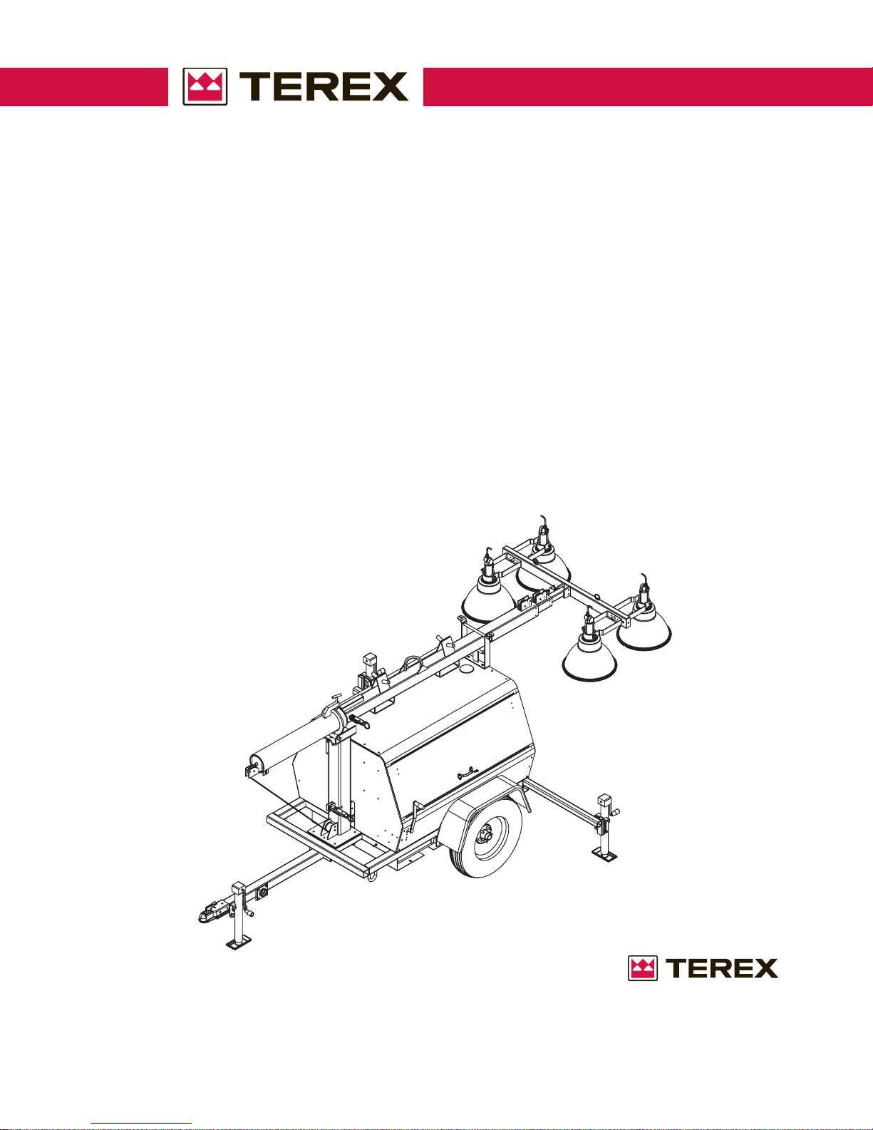
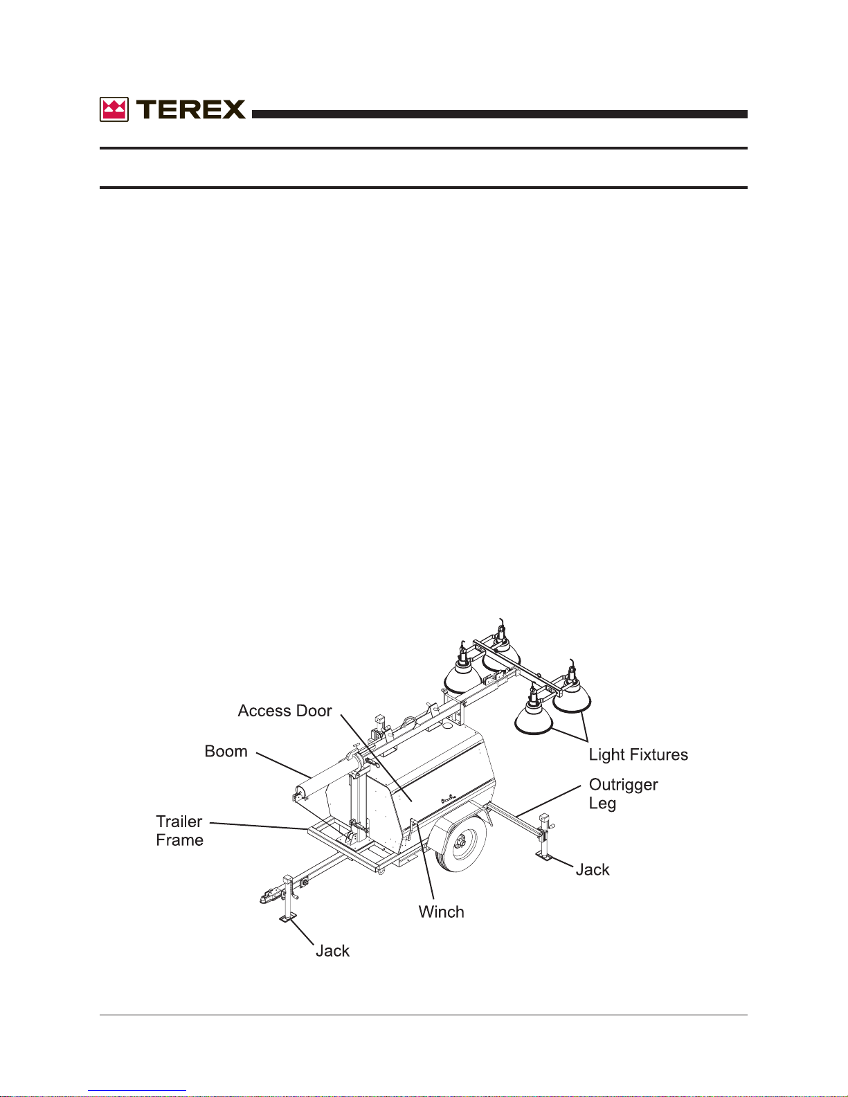
Light Tower
PART NUMBER 833002
REVISION A
November 2006
TOLL FREE 800-433-3026
FAX (Part s Dept) 800-633-5534
Part No. 833002 Rev A AL4000 Light Tower 1
P .O. BOX 3147
ROCK HILL, S.C. 29732 USA
Page 2
November 2006
TABLE OF CONTENTS
OPERATOR’S MANUAL
T o the Operator ................................................................................................................4
Safety Alert Symbols ........................................................................................................5
General Safety ............................................................................................................6-10
Receipt of Delivery Checklist.......................................................................................... 11
Transport & Towing.........................................................................................................12
Setup ........................................................................................................................13-16
Operating Instructions................................................................................................17-21
Maintenance .............................................................................................................22-24
Specifications and Dimensions.................................................................................25-26
T orque S pecifications..................................................................................................... 27
Troubleshooting.........................................................................................................28-32
Warrranty ..................................................................................................................33-34
Serial Number Record ................................................................................................... 35
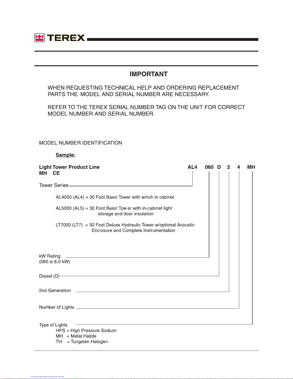
Model Number Identification ........................................................................................... 36
Recomended Oil ............................................................................................................ 37
Wire Rope Replacement...........................................................................................38-42
PARTS MANUAL
Wiring Diagrams.......................................................................................................44-50
General Information Parts Manual................................................................................... 52
Parts Ordering Information ............................................................................................. 53
Trailer Frame/Tongue/Outriggers ....................................................................................54
Fuel T ank .......................................................................................................................55
Axle Assembly................................................................................................................ 56
Cabinet Assembly .......................................................................................................... 58
Cabinet Assembly (Top & Doors) ................................................................................... 60
Cabinet Decals .............................................................................................................. 62
T ower Assembly ............................................................................................................. 63
4” T ower Section ............................................................................................................64
4” T ower Section (Sheave & Shim).................................................................................65
3” T ower Section ............................................................................................................66
2” T ower Section ............................................................................................................67
T ower Crossarm Fixture .................................................................................................68
6” Round Tube................................................................................................................69
2 AL4000 Light Tower Part No. 833002 Rev A
Page 3

November 2006
TABLE OF CONTENTS
PARTS MANUAL (Continued)
T ower Base Assembly....................................................................................................70
Winch Assembly.............................................................................................................72
Engine/Genset Assembly ............................................................................................... 74
Radiator Assembly.........................................................................................................75
Radiator Mounting Bracket............................................................................................. 76
Generator Mounting Bar ................................................................................................. 77
Electrical Control Box Assembly..................................................................................... 78
MH/HPS Light Fixture Assembly..................................................................................... 80
Ballast Assembly............................................................................................................ 82
Coil Cord & Junction Box ...............................................................................................83
Trailer Hitches ................................................................................................................84
AL4000 Options........................................................................................................85-86
Part No. 833002 Rev A AL4000 Light Tower 3
Page 4
November 2006
TO THE OPERATOR
DO NOT ATTEMPT TO SETUP, OPERATE, OR WORK ON THE LIGHT T OWER
UNLESS YOU HAVE READ AND STUDIED THIS MANUAL AND THE ENGINE AND
GENERATOR MANUALS CAREFULLY. READING THESE MANUALS WILL TEACH
YOU HOW TO SAFELY SETUP, OPERATE, AND PROPERLY MAINTAIN THE
TOWER AND ITS COMPONENTS.
REMEMBER THAT YOU ARE THE KEY TO SAFETY. GOOD SAFETY PRACTICES
NOT ONLY PROTECT YOU, BUT ALSO THOSE WORKING AROUND YOU. MAKE
THIS MANUAL A WORKING PART OF YOUR SAFETY PROGRAM.
An operator should never use drugs, alcohol or any other substance which can change his
alertness or coordination.
Do not work on this equipment when mentally or physically fatigued.
This manual is compiled from information available and current at time of approval for printing.
Terex reserves the right to improve its products without giving prior notice or incurring any obligation.
If this manual becomes lost, order a new one from Terex so future operation and maintenance
personnel may read these instructions.
4 AL4000 Light Tower Part No. 833002 Rev A
Page 5
November 2006
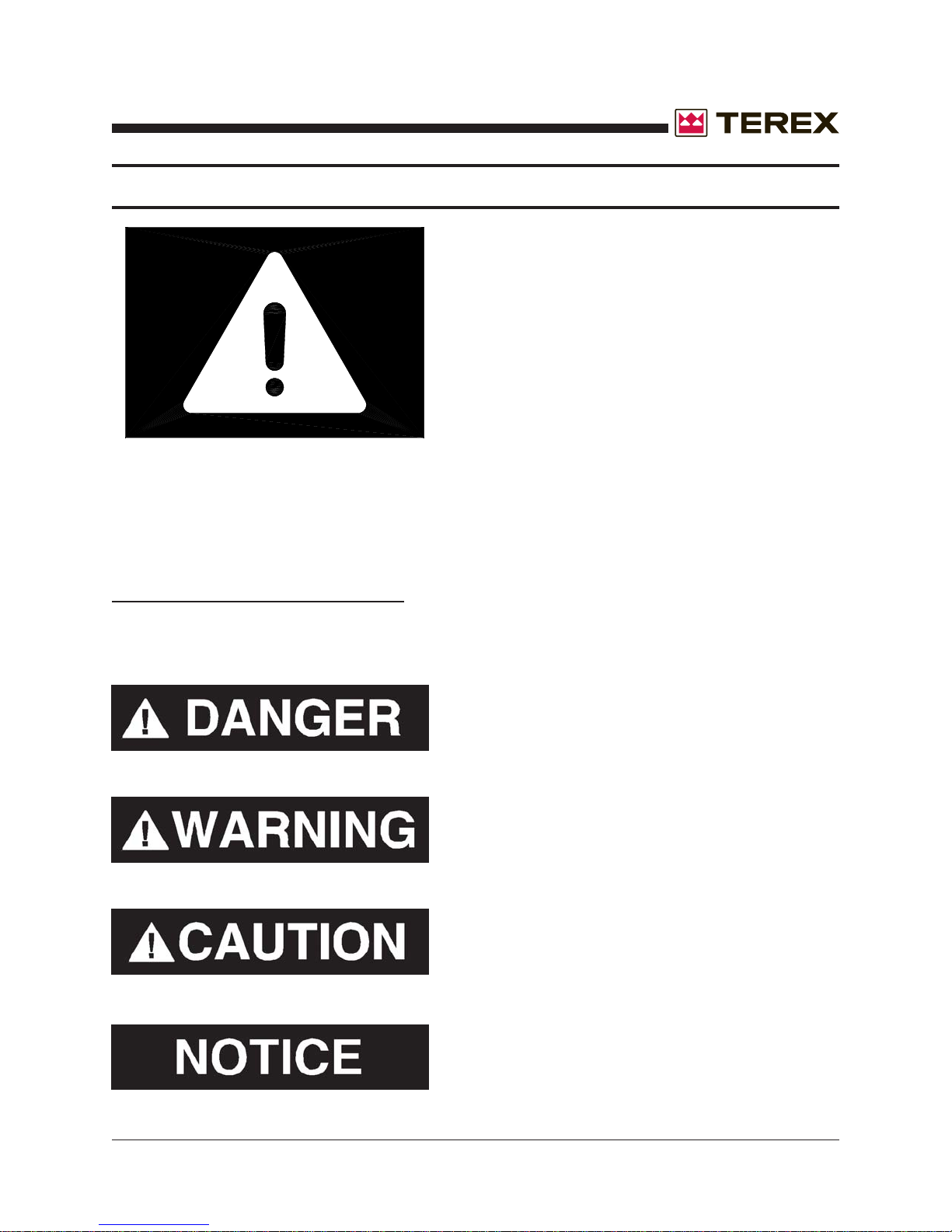
SAFETY ALERT SYMBOLS
MEANS:
ATTENTION! BE ALERT!
YOUR SAFETY IS INVOLVED
THIS SAFETY SYMBOL IS USED FOR IMPORTANT SAFETY MESSAGES. WHEN YOU SEE THIS SYMBOL, FOLLOW THE SAFETY
MESSAGE TO AVOID PERSONAL INJURY OR PROPERTY DAMAGE.
UNDERSTANDING SIGNAL WORDS
A signal word - DANGER, WARNING or CAUTION is used with the safety alert symbol.
DANGER Identifies the hazard or unsafe practice
that will result in severe injury or death.
WARNING Identifies the hazard or unsafe practice
that could result in severe injury or death.
CAUTION Identifies the hazard or unsafe practice
that could result in minor injury or property damage.
NOTICE Identifies important installation, operation
or maintenance information.
Part No. 833002 Rev A AL4000 Light Tower 5
Page 6
November 2006
GENERAL SAFETY
DO NOT OPERATE THE AL4000 LIGHT T OWER WITHOUT
READING THIS OPERATOR’S MANUAL.
DO NOT WORK ON OR OPERATE THE LIGHT TOWER WHILE UNDER THE INFLUENCE OF PERFORMANCE IMPAIRING DRUGS OR ALCOHOL.
SAFETY ALERT SYMBOL
Stop and take time to read ALL Safety alert messages. Follow the safety messages to avoid
personal injury or property damage.
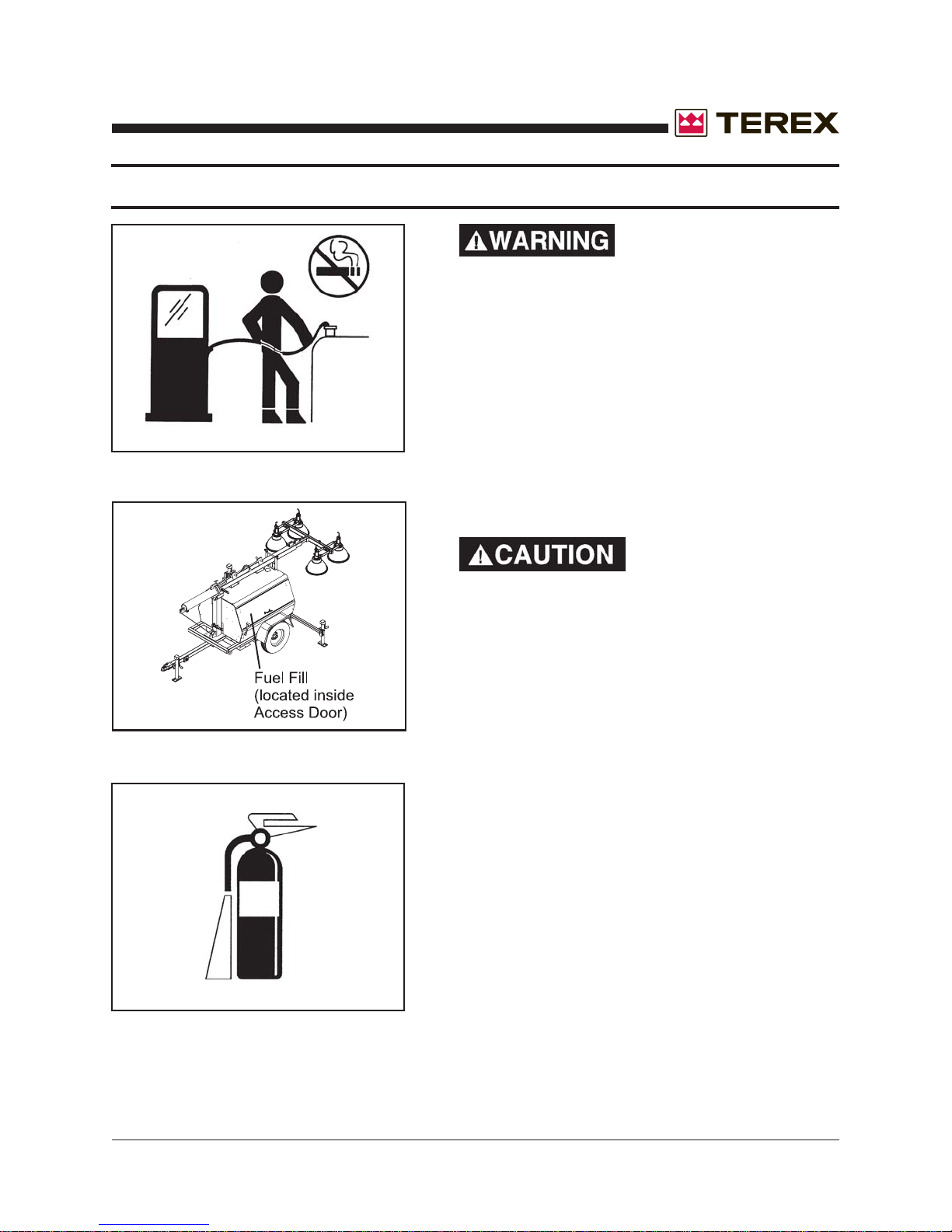
ACCIDENT PREVENTION
Use protective clothing and safety equipment.
Always wear approved safety equipment such as
gloves, safety boots, safety hard hat, goggles, ear
protection, and dust masks when necessary.
Wear protective clothing that is snug and belted
where required.
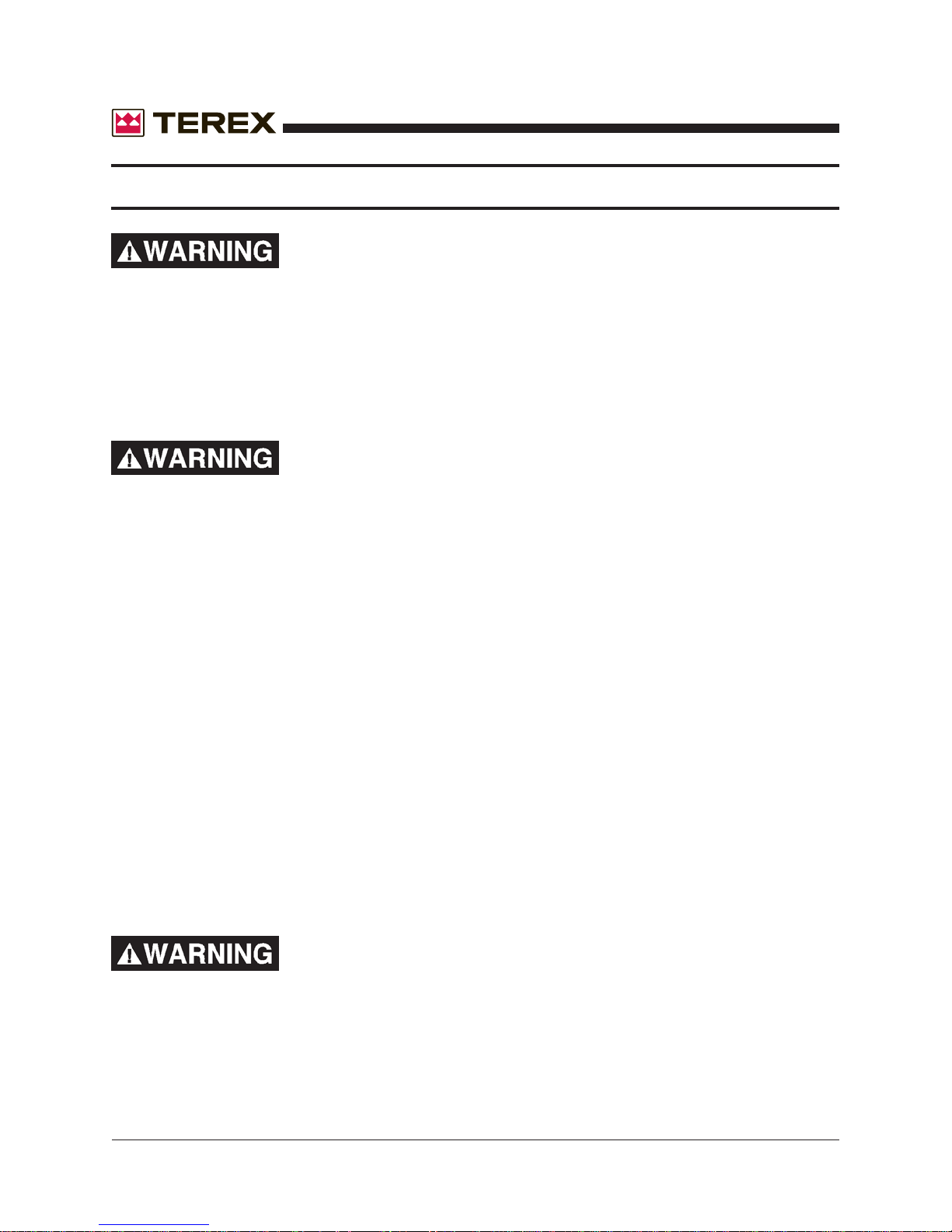
UNAUTHORIZED WELDING
UNAUTHORIZED
WELDING CAN CAUSE
STRUCTURAL FAILURE OR PERSONAL
INJURY.
DO NOT weld on any structural member.
6 AL4000 Light Tower Part No. 833002 Rev A
Any unauthorized welding or repair procedure will
void the warranty .
Page 7
November 2006
GENERAL SAFETY
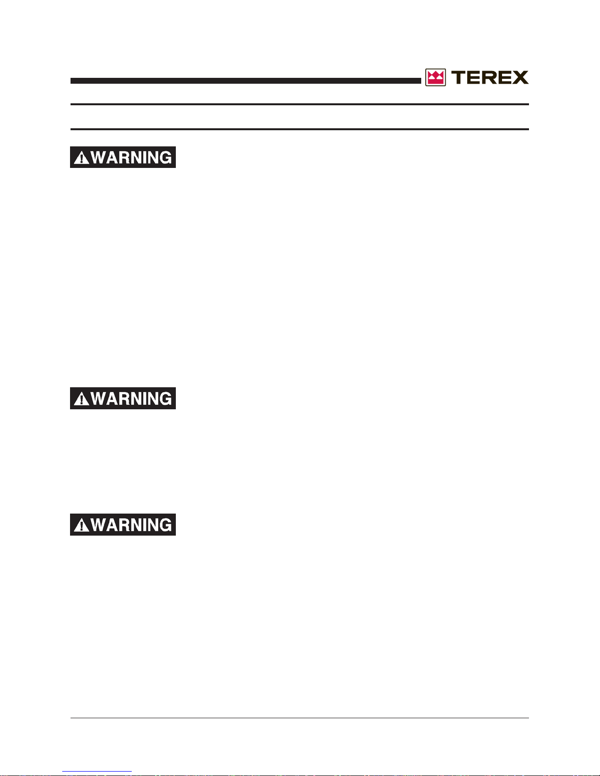
FUELING
ALWAYS handle fuel with care. It is highly flam-
mable.
ALWAYS stop engine before refueling. Fill fuel
tank outdoors.
Be sure the fuel supply has a positive shut-off
valve.
DO NOT replace fuel lines with materials different
from those supplied as original equipment.
FIRES CAN CAUSE
SEVERE PERSONAL
INJURY OR MACHINE
DAMAGE.
Prevent fires by keeping the light tower and its
surrounding area clean.
DO NOT refuel while smoking or when near open
flame or sparks.
DO NOT refuel the engine when it is hot. Allow to
cool for several minutes before refueling.
DO NOT spill fuel inside the engine compartment.
If fuel has leaked, wipe it up and have leak re-
paired before next use.
Have a fire extinguisher nearby . Be sure the
extinguisher is properly maintained and be familiar
with its use. Extinguishers rated ABC by the NFPA
are appropriate for all applications.
Part No. 833002 Rev A AL4000 Light Tower 7
Page 8
November 2006
GENERAL SAFETY
EXHAUST GASES ARE TOXIC. DO NOT USE INDOORS
UNLESS PROPERLY VENTILATED OR AN EXHAUST
SCRUBBER IS USED.
Check exhaust system regularly for leaks and ensure that the exhaust manifolds are secure and
not warped.
Make sure the unit is well ventilated.
ELECTRICAL SAFETY
This equipment utilizes high voltage circuits. Always exercise extreme caution when trouble
shooting or repairing any electrical circuit.
The electrical circuits in this light tower complete their paths back to the generator within the
equipment. The neutral conductor at the generator is bonded to the equipment frame. Ground
wires within the system are also bonded to the equipment frame.
Always ground the unit when possible. Consult local electrical codes for grounding
instructions.
A grounding lug has been added to the trailer frame for your convenience.
Disconnect electrical power and turn off engine before removing protective covers on high
voltage electrical enclosures.
Beware of a cut or damaged power cord. Have a qualified electrician replace immediately .
When troubleshooting indicates a malfunction in the high voltage AC system, pass the task to a
qualified and trained electrician.
DO NOT TOUCH HOT PARTS
The exhaust manifold and tail pipe are very hot. Parts of the engine are also hot. Use protective
gloves when handling hot parts.
The light fixtures become very hot during operations. To avoid burns, always allow any fixture to
cool before handling.
8 AL4000 Light Tower Part No. 833002 Rev A
Page 9
November 2006
GENERAL SAFETY
BATTERY HAZARDS
Lead acid batteries can be dangerous. The sulfuric acid in the battery can cause severe skin and
eye burns. The hydrogen gas emitted during charging can explode if an arc or flame is present.
DO NOT smoke while servicing the battery.
DO NOT allow tools to touch battery terminals and create an arc.
Disconnect the negative terminal of the battery when working on the engine or other parts to
prevent accidental arcing. Disconnect the negative cable at the end away from the battery.
DO NOT remove the vent caps when charging the battery.
Always wear eye protection when servicing the battery .
If acid gets on skin or eyes, immediately flush under running water and obtain medical attention.
METAL HALIDE LAMPS PRODUCE SHORTWAVE ULTRAVIOLET RADIATION AND CAN CAUSE SERIOUS SKIN AND EYE
BURNS OR INFLAMMATION IF THE OUTER ENVELOPE OF
THE LAMP IS BROKEN OR PUNCTURED.
DO NOT use where people will remain close to the lamps for more than a few minutes unless
adequate shielding or other safety precautions are used.
KEEP ALL BODY P ARTS AND CLOTHING AW AY FROM
MOVING PARTS
Loose jackets, shirts, sleeves, and especially neckties should not be worn while working on or
running the unit.
Only remove guards or protective devices from unit temporarily to gain access for maintenance.
Always replace guards immediately after servicing. Never remove guards while unit is operating.
Keep your hands away from moving parts, particularly clear of the radiator fan and alternator
belts when the engine is running.
Part No. 833002 Rev A AL4000 Light Tower 9
Page 10
November 2006
GENERAL SAFETY
BEWARE OF TRAFFIC HAZARDS
Stand clear of traf fic when st arting or checking the unit along the road.
Check the fuel tank, oil pan, and fuel and oil lines for leaks that would spill fuel or oil on the road.
Check fasteners and mounting brackets periodically to insure all are tight and nothing is in
danger of falling off during transit.
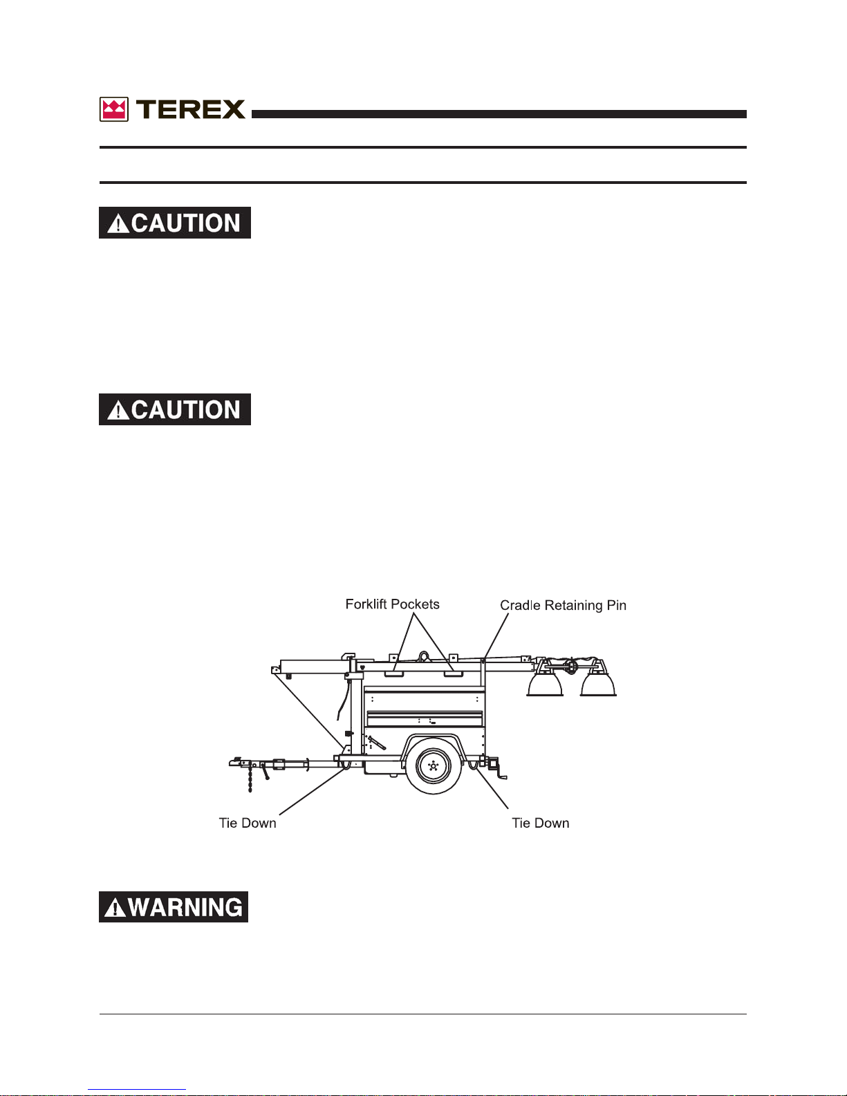
Be careful when lifting. Never suspend any other equipment
from the shipping tie downs.
Use the lifting eye or forklift pockets on the tower for lifting the trailer and tower assembly only
(with tower and cabinet).
Make sure any tie-downs at the bottom of the trailer are released, and the cradle retaining pin is
inserted and secured, prior to lifting.
NEVER CLIMB ON TOP OF THE CABINET AND/OR TOWER
WHEN ERECTED OR RETRACTED.
10 AL4000 Light Tower Part No. 833002 Rev A
Page 11
November 2006
RECEIPT OF DELIVERY CHECKLIST
The tower will be serviced, tested and ready for operation upon delivery . Terex recommends the
following checks:
Insure there is no freight handling damage which should be charged against the carrier.
Make sure the telescoping boom is secure.
Make sure the crosshead assembly is secure.
Check the front and rear jacks for security and proper operation.
Check the outriggers for security and proper operation.
Check that the tires are not damaged, under inflated or that any lugs are loose.
Check the engine/generator for obvious damage, loose connections, or leaks.
Check the control panel for damage or loose connections.
Check the boom wires for obvious damage or loose connections.
Check the light fixtures for damage to the lamps, lenses, reflector or etc.
Check the winches, cables and pulleys for damage and proper operation.
Check the exhaust system for damage.
Check all fluid levels; battery , radiator , and engine oils.
Insure manuals are in the pocket provided inside the unit.
Part No. 833002 Rev A AL4000 Light Tower 11
Page 12
November 2006
TRANSPORT & TOWING
1. Using the front leveling jack, securely attach the light tower to the transporting vehicle.
2. Insure that the coupler is properly secured to the towing vehicle and attach the safety
chains.
ALWAYS USE THE PROPER TRAILER HITCH AND SAFETY
CHAINS. OBEY ALL LOCAL OR STATE D.O.T. LA WS WHEN
TOWING A LIGHT TOWER.
FAILURE TO PROPERLY SECURE THE TRAILER TO THE
TOWING VEHICLE MAY RESULT IN SERIOUS INJURY OR
DEATH.
3. Retract and rotate the front leveling jack into its stowed position.
4. Check the tires for proper inflation (32psi) and verify the lug nuts are tight.
5. Position all outriggers and jacks into the stowed or travel position.
6. Verify that the fixtures are secure and ready for transport.
7. Secure all loose locking pins and retainers.
8. Make sure all doors are closed and tightly locked.
9. Remove tire chocks.
T owing of a Terex light tower is approved with the light fixtures in place on the crosshead assembly for all off road
terrain and highway towing as long as the following speed
limits are followed:
Highway towing - 60 MPH max
Off road towing - 10 MPH max
Severe damage may occur from excessive speeds. Damage
created by abuse will void the manufacturer’s warranty .
12 AL4000 Light Tower Part No. 833002 Rev A
Page 13
November 2006
SETUP
A. Move the light tower to desired location keeping the following in mind:
1. The light tower should not be placed where those working under the light are either:
a. Forced to look into the light regularly.
b. Forced to work with their backs to the light (shadows will block the light from the
work area).
2. The area where the tower is positioned should be relatively level for safe and proper
operation of the unit.
3. The light tower should be located on the same level or on ground higher than the work
area.
B. Use tire chocks in front of and behind each tire whenever possible. Always use tire
chocks on an incline.
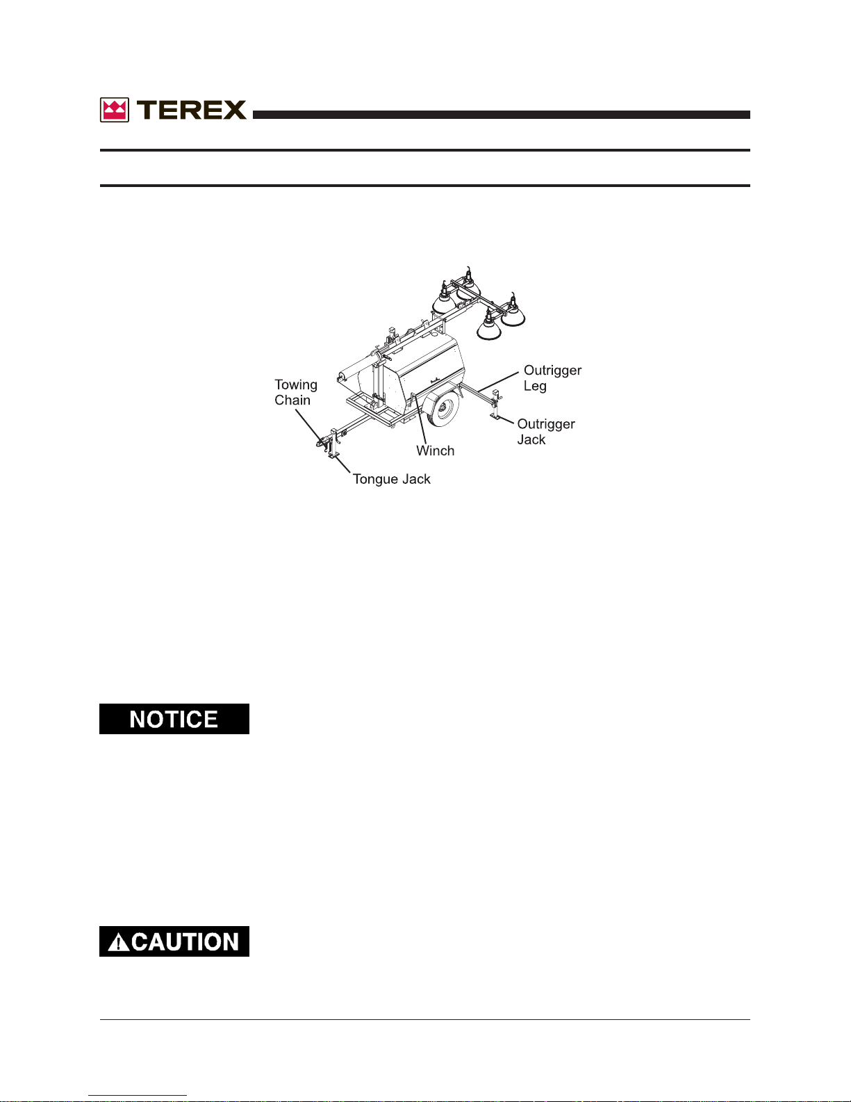
C. Disconnect the towing chain.
D. Unhitch from the towing vehicle as follows:
1. Rotate the tongue jack into position (90 degrees), release the hitch pin and raise the
tongue off the towing vehicle.
E. Level the trailer , using the jacks as follows:
1. Extend the front outriggers until the outrigger pins lock into place. Rotate
the jack on each outrigger into vertical position and lock into place.
2. Rotate the rear jack and lock into the vertical position.
3. Start at the highest jack position. Rotate the jack handle until the jack foot touches the
ground.
4. Raise the other jacks to level trailer.
OUTRIGGERS ARE NOT DESIGNED TO LIFT THE TIRES OFF
THE GROUND.
Insure that all jacks are down to prevent the tower from
tipping over backwards when raised.
NEVER ATTEMPT TO MOVE THE TOWER WHILE THE LEVELLING JACK ARE DOWN. SERIOUS MACHINE DAMAGE
WILL RESULT.
Part No. 833002 Rev A AL4000 Light Tower 13
Page 14
SETUP
F. When applicable, drive grounding rod into earth. (Grounding rod not included)
1. Drive the rod into the ground and secure the grounding wire to the lug located on the
trailer frame.
November 2006
G. When applicable, install the floodlights on the crossarm.
1. Remove the light fixtures from their packing boxes and install them on the crossarm
with the lens facing the ground.
2. The cord on the fixture should be on the side closest to the trailer so the cord entry is
beneath the fixture when the tower is raised (this reduces moisture problems and
insures the water weep hole in the fixture is down).
3. Set the vertical aim for each light fixture by adjusting the light fixtures and tightening
the lower bolt.
Never adjust fixtures with power on.
4. Set the spread between the fixtures horizontally by adjusting the fixtures and tightening
the mounting nut.
5. The light fixtures may be left on the unit when towed around the job site.
6. Plug each fixture into the receptacles provided. Plug into the numbered receptacles in
a clockwise rotation starting at the upper or 1:00 o’clock position. This makes trouble
shooting easy without lowering the tower.
If Tungsten Halogen lamps are used, the cord must be routed
and secured away from the fixture. Failure to do so may
result in cord burn-through and short circuit due to the high
fixture temperature.
14 AL4000 Light Tower Part No. 833002 Rev A
Page 15
November 2006
SETUP
H. Raising the tower as follows:
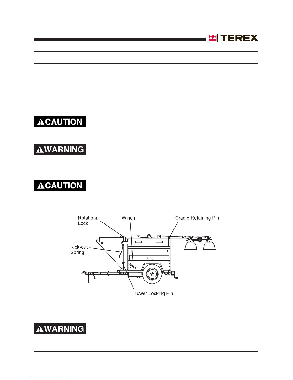
1. Remove the tower travel locking pin from the cradle at the rear of the cabinet.
2. Remove the tower locking pin from the tower base. Using the lower pivot winch, raise
the tower to the vertical position. Reinsert the tower locking pin into the tower base.
If there is any difficulty in tilting the boom vertically , check the
tailhook and hook. The tailhook may need to be released.
BEWARE OF PINCH POINTS WHEN ERECTING OR STOWING THE TELESCOPING TOWER. A LOSS OF DIGITS OR
LIMBS MAY RESULT FROM UNSAFE PRACTICES.
Do not attempt to lean the tower down when it is extended.
Serious damage may occur.
WHEN RAISING THE BOOM, MAKE SURE THE BOOM
WIRING DOES NOT BECOME ENTANGLED.
Part No. 833002 Rev A AL4000 Light Tower 15
Page 16
November 2006
SETUP
THE AUTOMATIC BRAKE MUST BE WORKING ON THE
TELESCOPING WINCH. THE WINCH SHOULD NOT ALLOW
THE TOWER TO DROP DOWN WHEN THE HANDLE IS
RELEASED.
UNDER NO CIRCUMSTANCES SHOULD THE LIGHT
TOWER BE MOVED WHEN THE BOOM IS IN A VERTICAL
POSITION.
3. Release the tower rotational lock and adjust the lights to the desired area. Once
positioned correctly , retighten the rotational lock.
16 AL4000 Light Tower Part No. 833002 Rev A
Page 17
November 2006
OPERATING INSTRUCTIONS
READ ALL DIRECTIONS IN MANUAL CAREFULLY
BEFORE OPERATING EQUIPMENT
DO NOT RAISE TOWER IN THE VICINITY OF
OVERHEAD POWER LINES!
1. Move Light Tower to desired location keeping the following in mind:
A. The light tower should not be placed where those working under the light are either:
1. Forced to look into the light regularly .
2. Forced to work with their backs to the light (shadows will block the light from the
work area).
B. The area where the tower is positioned should be relatively level.
C. The light tower should be located on the same level or on ground higher than the area
being lighted (higher light mounting heights reduce the shadow length).
D. Unit should be level to insure smooth trouble-free tower telescoping. Tower may not
telescope down properly when unit is not level.
2. Unhitch from the towing vehicle as follows:
A. Engage the trailer braking system, especially if trailer is not on level ground.
CAUTION: If electrical or manual braking system is not supplied, chock the wheels
instead.
B. Swing the tongue jack into position and raise the tongue off the towing vehicle.
3. Level the trailer, using the jacks as follows:
A. Extend the rear outriggers until the springs lock into place. Swing the jack on each
outrigger into vertical position.
B. St art at the highest jack position. Rot ate the jack handle until the jack foot touches the
ground.
C. Raise the other jacks to level trailer
down to prevent the tower from tipping over backwards when raised.
ensure that the rear jacks are
4. Drive grounding rod into earth.
Part No. 833002 Rev A AL4000 Light Tower 17
Page 18
OPERATING INSTRUCTIONS
5. Install the floodlights on the crossarm:
A. Remove the light fixtures from the tower by rotating the wingnuts to free the lights.
Install them on the cross arm studs with the lens facing the ground.
B. The cord on the fixture should be on the side closest to the trailer so the cord entry is
beneath the fixture when the tower is raised ( this reduces moisture problems and
insures the water weep hole in the fixture is down).
C. Set the vertical aim for each light fixture by adjusting the light fixtures and tightening the
T-handle located on the fixture.
D. Set the spread between the light fixtures horizontal aiming by adjusting the fixtures and
tightening the wing nut.
E. The unit may be transported with the light fixtures mounted on the crossarm if they
are pointed toward the ground.
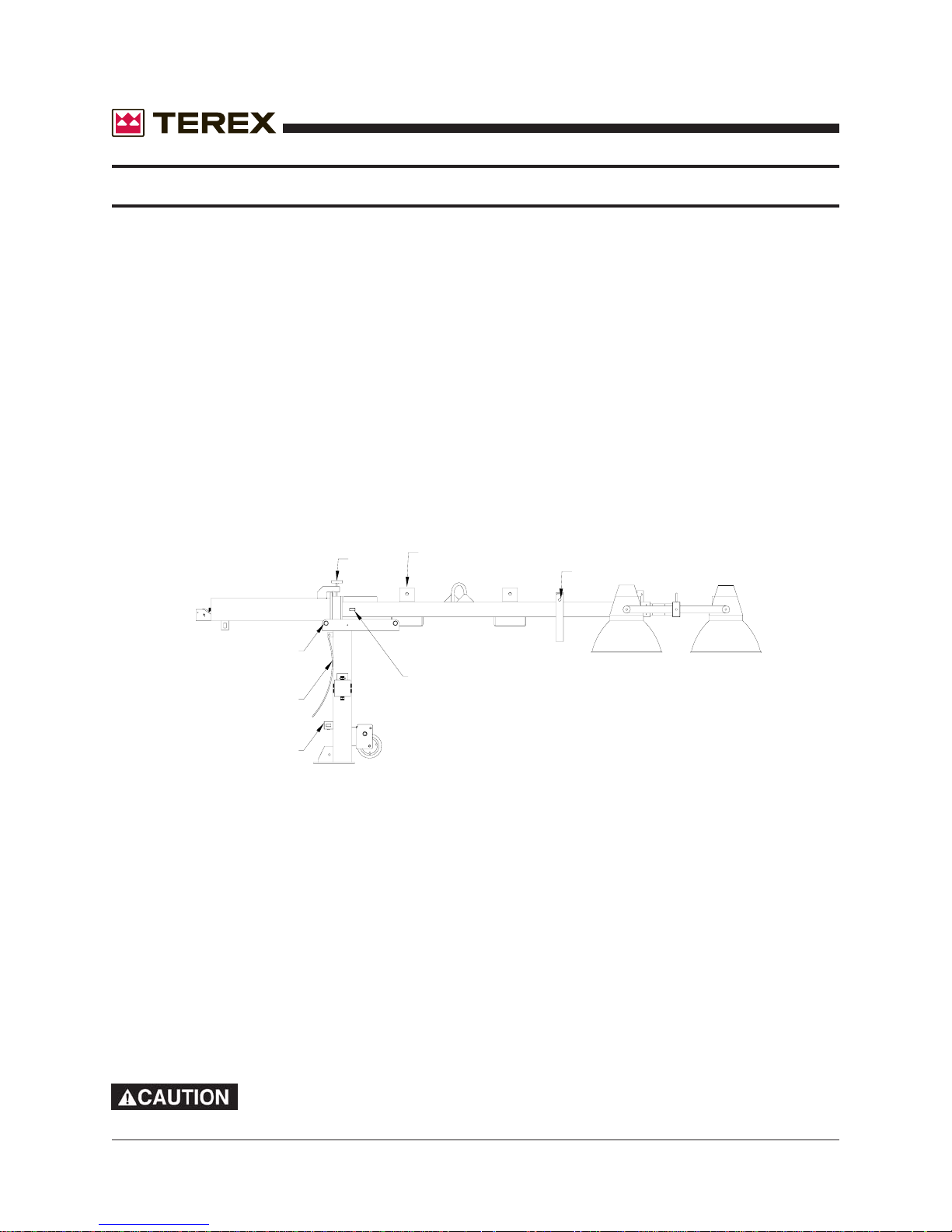
"T" BOLT
FIXTURE TRAVEL STORAGE BRACKETS
November 2006
TRAVEL LOCKING PIN
PIVOT PIN
TELESCOPING LOCKING PIN
KICK-OUT SPRING
VERTICAL LOCKING PIN
6. Raising the tower (refer to drawing above):
A. Remove the tower travel-locking pin from the cradle at the rear of the cabinet.
B. Aim the fixtures, both horizontally and vertically, to the estimated angles that will light
the work area.
C. Using the winch, raise the tower to the vertical position. The tower-locking pin at the
base of the pivot post will lock automatically and you will hear it “snap” into place.
Insert manual pin into locking device.
D. Release the tension on the cable by backing the winch off slightly and pull the tele-
scoping locking pin on the galvanized tower section. Hold this out while turning the
winch to raise the tower. After the tower has telescoped slightly, the locking pin can be
released. Raise the tower to the desired height.
DO NOT ATTEMPT TO LEAN THE TOWER DOWN BELOW 45°
WHEN IT IS EXTENDED-SERIOUS DAMAGE MAY OCCUR!
18 AL4000 Light Tower Part No. 833002 Rev A
Page 19
November 2006
OPERATING INSTRUCTIONS
7. Start the Engine/Generator Set
A. Ensure the circuit breakers are turned “OFF”. This prevents the engine from
starting under load and prevents electrical equipment from being subjected to
improper voltage and frequency .
B. Check the oil, fuel, and coolant levels. If the fuel tank is empty, it may be necessary to
bleed the fuel line after filling the tank (see engine instruction book for procedure).
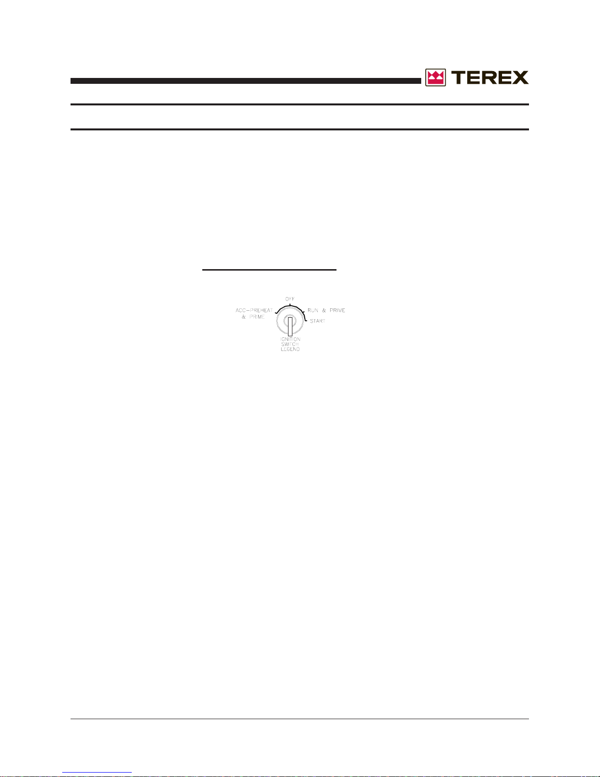
C. Turn the ignition switch to the “ACC” position (see diagram below). Press the preheat
push-button for a
button longer than the time specified or damage may occur.
maximum of 20 SECONDS. Do not engage the preheat
D. Turn the ignition switch to the “ST AR T” position to engage the engine. After the engine
starts, release the switch so that it returns to the “RUN” position. Let the engine come
up to speed and stabilize (review the engine operating procedures in the manufacturers handbook). Note: If engine will not start, leave switch in run position for additional
10-20 seconds to completely prime the fuel system. Then repeat step “C” and start
engine.
E. Turn on the main circuit breaker.
8. Turn on the floodlights:
A. Turn the circuit breakers “ON” and ensure all lamps come on. Allow a minimum of
two (2) minutes for lamps to reach full luminance.
B. If required, rotate the tower to aim the lights as desired. Tighten the tower rotating
locking bolt.
C. Adjust the tower vertically and adjust lighting direction of individual fixtures if required.
9. Turn off the floodlights:
Part No. 833002 Rev A AL4000 Light Tower 19
Page 20
OPERATING INSTRUCTIONS
A. Turn light circuit breakers of f.
B. Turn engine switch to “OFF” to shut down the engine.
DO NOT SHUT DOWN ENGINE PRIOR TO TURNING LIGHTS OFF.
ALLOW LAMPS TO COOL AT LEAST TEN (10) MINUTES BEFORE
MOVING THE TOWER TO AVOID BREAKING LAMPS.
10. Lowering the tower to traveling position:
A. Using the winch, telescope the tower down to its fully retracted position until the
telescoping locking pin snaps into place.
November 2006
B.
vertical lock pin at the bottom of the pivot post. This insures the tower is completely
lowered and cannot be damaged by telescoping out while in the travel position.
C. Loosen rotating lock.
D. Rotate the tower so that the groove in the galvanized ring at the pivot is pointing to the
rear of the trailer to enable the tower to be lowered into the travel position.
E. Tighten rotating lock.
F. Pull the vertical locking-pin at the base of the pivot post (the kick-out spring should
provide sufficient pressure to start the tower pivoting over).
G. Let out on the winch cable to lower the tower into the cradle.
H. Insert the rear tower horizontal travel-locking pin into the cradle.
Ensure that the telescoping locking pin locks before pulling the
20 AL4000 Light Tower Part No. 833002 Rev A
Page 21
November 2006
OPERATING INSTRUCTIONS
11. Relocating light tower to new location:
A. Ensure that tower has been properly lowered (see section 10) and locking pins are
engaged.
B. Ensure all fixtures are pointed toward the ground, or mounted on the fixture storage
brackets on the lower tower section.
C.
D. Ensure that the coupler is properly secured to the towing vehicle and safety chains are
attached (if supplied). Release any manual braking mechanism (if supplied).
E. Do not tow at excessive speeds (60 mph – 100-kmh maximum) as the weight of the
light tower can cause loss of vehicle control, especially under emergency
stopping conditions. The standard trailer has no towing brakes; therefore
allow extra distance for stopping.
12. Use of light tower auxiliary power:
A. One (1) 30amp/240v Twist-Lock and (1) 20 amp/120v duplex receptacles with GFI are
provided forauxiliary power.
B. Total auxiliary power cannot exceed main circuit breaker rating. Each lamp operating
consumes 9.2 amps @ 120 vac.
C. Before plugging in auxiliary power cords, feed them up through the trailer frame and
attach to receptacles. Close the cabinet doors to protect control panel and
other components from weather (see Miscellaneous Specifications and Routine
Maintenance section for power control details).
All jacks must be raised and all outriggers locked into travel position.
Part No. 833002 Rev A AL4000 Light Tower 21
Page 22
November 2006
MAINTENANCE
MINIMUM MAINTENANCE PROCEDURES:
The following maintenance intervals are only suggested by Terex. Y ou should always check your
engine owner’s manual for specific information. Should you find any discrepancies between the
T erex Manual and the Engine Manufacturer’s Manual always follow the Engine Manufacturer’s
Manual.
Twice Daily:
-Check the crankcase oil and fill as required.
Daily:
-Check the engine and generator for any loose bolts, connections, and fittings.
-Check the coolant levels and fill as required.
Note: Use a 50% solution of water and antifreeze for the engine coolant.
Weekly:
-Check the air cleaner and clean as required.
-Inspect the radiator fins for damage or clogging.
Bi-weekly:
-Check the engine oil quality and change as required.
Bi-Monthly or every 250 hours:
-Change the engine crankcase oil.
Six months or every 500 hours:
-Replace the oil filter.
-Check valve clearances (consult Manufacturer’s Manual)
-Check electrical components and clean as required.
-Check electrical wiring for chafing, wear and replace as needed.
Yearly or every 1,000 hours:
-Clean or replace the fuel filter.
-Clean or replace the fuel pump strainer, if equipped.
-Check the head and manifold bolts for tightness.
-Clean or replace the air filter.
22 AL4000 Light Tower Part No. 833002 Rev A
Page 23
November 2006
MAINTENANCE
CLEANING:
The Light Tower employs various electronic controls that may be damaged by liquid spray
washing or high pressure washing. Follow these procedures to prevent any damage to these
components.
DO NOT SPRAY WATER INTO THE UNIT WHILE IT IS
RUNNING. THIS MAY RESULT IN INJURY OR DEATH BY
ELECTRIC SHOCK.
Exterior Cleaning:
1. The exterior housing may be washed by most conventional cleaners and methods.
2. The exterior housing may be waxed using any conventional automotive wax.
Interior Cleaning:
1. Using a damp cloth covered with a mild soap, carefully clean around any electric controls,
generator, and thermostats.
Light Fixture Cleaning:
1. The light fixtures and bulbs may be cleaned using any window cleaner.
THE LIGHT FIXTURES ARE VERY HOT, ALLOW TO COOL
BEFORE PERFORMING ANY CLEANING TO THE FIXTURE,
BULBS OR LENSES.
Part No. 833002 Rev A AL4000 Light Tower 23
Page 24

November 2006
MAINTENANCE
MANUAL WINCH
Maintain a light film of automotive-type grease on the pinion, drum gear, and the O.D. of the drum
bearing at all times. Keep the ratchet pawl pivot, pinion shaft bushings, and pinion threads lubri
cated with automotive engine oil at all times. Before each use, check the brake friction discs for
wear. If less than 1/16” thick, cracked, or broken, replace IMMEDIATELY. Ratchet pawl should
“click” when tower is raised, and not when it is lowered. Always be alert for any fraying of cables, and replace any damaged cables IMMEDIATELY. Never stand under any object lifted by
the winch.
ELECTRIC WINCH
The electric winch is permanently sealed and does not need any periodic lubrication.
Always be alert for any fraying of cables, and replace any damaged cables IMMEDIATELY.
Never stand under any object lifted by the winch.
NOISE LEVEL
Mean SPL (sound pressure level) hemispherically at 7 meters: 63dBA
Sound Power Level (63 dBA + 20 log d + 7.8): 90.0 LWA re 1 pW
D = 7 meters
24 AL4000 Light Tower Part No. 833002 Rev A
Page 25
November 2006
SPECIFICATIONS & DIMENSIONS
Part No. 833002 Rev A AL4000 Light Tower 25
Page 26
November 2006
SPECIFICATIONS & DIMENSIONS
TEREX Amida model AL4000 series light tower provides mobile, trailer mounted floodlighting for
nighttime maintenance, construction, mining, and emergency work. It consists of a trailer with a
diesel powered 6 kW 60Hz (50 Hz units available) generator, and a 30 foot cable actuated tower
with four (4) 1000 watt floodlight fixtures. It is ideally suited for heavy-duty use and is built to
meet the following specification:
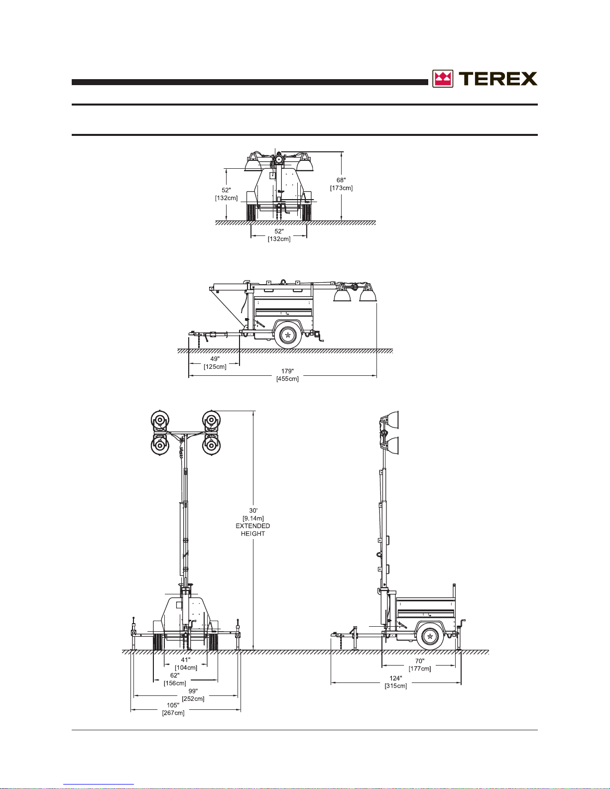
DIMENSIONS
Overall length, travel position w/fixtures & tongue 179” (4547 mm)
Overall length, tower vertical w/tongue & jacks 124” (3150 mm)
Trailer frame length 70” (1778 mm)
Overall height, floodlighting position 30’ (9114 mm)
Overall height, travel position 68” (1727 mm)
Overall width with fenders 62” (1575 mm)
Overall width with outriggers pulled out 105” (2667 mm)
Trailer frame width 41” (1041 mm)
Tongue length 49” (1245 mm)
Wheel size 15” (381mm)
Axle Rating 3500 lb. (1588 kg)
Tongue weight travel position 100 lb. (45.4 kg)
Total weight no fuel 2050 lb. (930 kg)
Fuel Capacity 30 gal. (114 kg)
Unit weight with full fuel tank 2250 lb. (1020 kg)
Max Highway Speed 60 mph (97 kmh)
NOISE LEVEL
Mean SPL (sound pressure level) hemispherically at 7 meters: 63dBA
Sound Power Level (63 dBA + 20 log d + 7.8): 90.0 LWA re 1 pW
D = 7 meters
DO NOT USE TOWER IN WIND SPEEDS ABOVE 62 MPH (100 KMH).
This section details specifications and maintenance not covered in the operators and troubleshooting sections of this manual and the AL4000 specification sheets.
BRAKE SYSTEM
Electrical or mechanical brakes are not standard equipment on the AL4000. Contact your dealer
or the factory for option information.
26 AL4000 Light Tower Part No. 833002 Rev A
Page 27
November 2006
TORQUE SPECIFICATIONS
MISCELLANEOUS SPECIFICATIONS
The Amida AL4000 light tower is built to NEC standards.
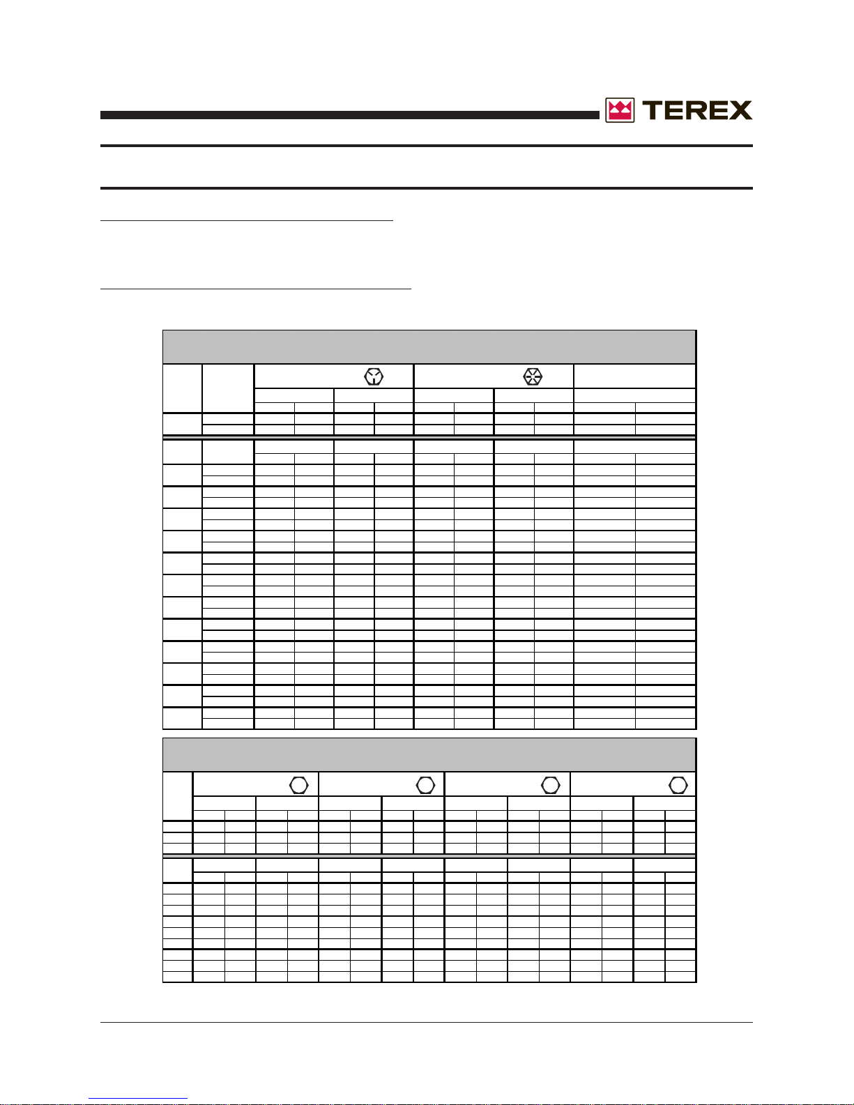
FASTENER TORQUE SPECIFICATIONS
All fasteners should be torqued to the following specifications in lb-ft (lb-in):
SAE FASTENER TORQUE CH ART
• T his chart i s t o be used as a guide only unless noted elsewhere i n th is manual •
SIZE THREAD
1/4
5/16
3/8
7/16
1/2
9/16
5/8
3/4
7/8
1
1.125
1.25
1.5
20
28
18
24
16
24
14
20
13
20
12
18
11
18
10
16
9
14
8
12
7
12
7
12
6
12
in-lbs Nm in-lbs N m in-lbs Nm in-lbs N m in-lbs Nm
100 11.3 80 9 140 15.8 110 12.4 130 14.7
90 10.1 120 13.5 120 13.5 160 18 140 15.8
ft-lbs Nm ft-lbs Nm ft-lbs Nm ft-lbs Nm ft-lbs Nm
13 17.6 17 23 18 24 25 33.9 21 28.4
14 19 19 25.7 20 27.1 27 36.6 24 32.5
23 31.2 31 42 33 44.7 44 59.6 38 51.5
26 35.2 35 47.4 37 50.1 49 66.4 43 58.3
37 50.1 49 66.4 50 67.8 70 94.7 61 82.7
41 55.5 55 74.5 60 81.3 80 108.4 68 92.1
57 77.3 75 101.6 80 108.4 110 149 93 126
64 86.7 85 115 90 122 120 162 105 142
80 108.4 110 149 120 162 150 203 130 176
90 122 120 162 130 176 170 230 140 189
110 149 150 203 160 217 210 284 180 244
130 176 170 230 180 244 240 325 200 271
200 271 270 366 280 379 380 515 320 433
220 298 300 406 310 420 420 569 350 474
320 433 430 583 450 610 610 827 510 691
350 474 470 637 500 678 670 908 560 759
480 650 640 867 680 922 910 1233 770 1044
530 718 710 962 750 1016 990 1342 840 1139
590 800 790 1071 970 1315 1290 1749 1090 1477
670 908 890 1206 1080 1464 1440 1952 1220 1654
840 1138 1120 1518 1360 1844 1820 2467 1530 2074
930 1260 1240 1681 1510 2047 2010 2725 1700 2304
1460 1979 1950 2643 2370 3213 3160 4284 2670 3620
1640 2223 2190 2969 2670 3620 3560 4826 3000 4067
Grade 5
DRYLUBED
LUBED DRY LUBED DRY
Grade 8
A574 High Strength
Black Oxide Bolts
LUBEDDRYLUBED
LUBED
METRIC FASTENER TORQUE CHART
• T his chart i s t o be used as a guide only unless noted elsewhere i n th is manual •
Size
(mm)
in-lbs Nm in-lbs Nm in-lbs Nm in-lbs Nm in-lbs Nm in-lbs Nm in-lbs Nm in-lbs Nm
16 1.8 21 2.4 41 4.63 54 6.18 58 6.63 78 8.84 68 7.75 91 10.3
5
19 3.05 36 4.07 69 7.87 93 10.5 100 11.3 132 15 116 13.2 155 17.6
6
45 5.12 60 6.83 116 13.2 155 17.6 167 18.9 223 25.2 1.95 22.1 260 29.4
7
ft-lbs N m ft-lbs Nm ft-lbs N m ft-lbs Nm ft-lbs N m ft-lbs Nm ft-lbs N m ft-lbs Nm
5.4 7.41 7.2 9.88 14 19.1 18.8 25.5 20.1 27.3 26.9 36.5 23.6 32 31.4 42.6
8
10.8 14.7 14.4 19.6 27.9 37.8 37.2 50.5 39.9 54.1 53.2 72.2 46.7 63.3 62.3 84.4
10
18.9 25.6 25.1 34.1 48.6 66 64.9 88 69.7 94.5 92.2 125 81 110 108 147
12
30.1 40.8 40 54.3 77.4 105 103 140 110 150 147 200 129 175 172 234
14
46.9 63.6 62.5 84.8 125 170 166 226 173 235 230 313 202 274 269 365
16
64.5 87.5 86.2 117 171 233 229 311 238 323 317 430 278 377 371 503
18
91 124 121 165 243 330 325 441 337 458 450 610 394 535 525 713
20
124 169 166 225 331 450 442 600 458 622 612 830 536 727 715 970
22
157 214 210 285 420 570 562 762 583 791 778 1055 682 925 909 1233
24
* An anti-seize lubricant MUST be used on all stainless steel hardware.
Part No. 833002 Rev A AL4000 Light Tower 27
DRYLUBED
Class 10 . 9Class 8 . 8
LUBEDDRYLUBED
LUBED DRY LUBED DRYLUBED DRY LUBED DRY
10.9 12.98.84.6
DRY
Class 1 2.9Class 4 . 6
LUBED DRY
Page 28
November 2006
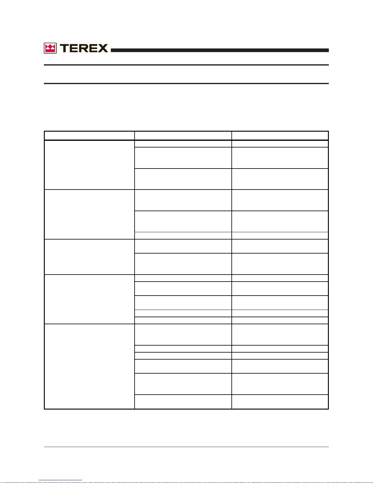
TROUBLESHOOTING
The engine and generator are set at the factory . These units are tested and set to 1800
RPM at 60 HZ for proper operation in the field. These units should never require additional
adjustments in the field. Adjustments should only be made by a qualified service technician,
otherwise the manufacturer’s warranty may become void.
TROUBLE POSSIBLE CAUSE REMEDY
1.Boom will not rise to a.Yoke pin is in place a.Remove yoke pin
the operating position. b.Defective cable b.Have a trained
or pulley mechanic examine and
repair as needed
c.Defective winch c.Have a trained
mechanic examine
and replace as needed
2.Boom will not telescope. a.Defective winch a.Have a trained
mechanic examine
and replace as needed
b.Broken cable or pulley b.Have a trained
mechanic examine
and replace as needed
c.Telescope lock pin closed c.Open telescope lock pin
3.Engine will not turn over a.Dead battery a.Check the battery voltage or
loose cables
b.Engine has seized due to loss b.Have a trained
of fluids mechanic examine and
repair as needed
4.Engine turns over but will a.Empty fuel tank a.Fill tank with #2 diesel fuel
not start b.Clogged fuel lines or filter b.Check and clean the fuel
system as needed
c.Leaking fuel lines or a loss c.Replace any leaking fuel lines
of prime and tighten connections
d.Heater elements burned out d.Replace heater elements
e.Fuel line solenoid is not open e.Replace fuel line solenoid
5.Engine runs rough a.Clogged or leaking fuel system a.Replace fuel lines, tighten all
connections, inspect the pickup
tube and inspect the fuel filter
b.Clogged exhaust system b.Clear the exhaust system
c.Clogged air filter c.Clear air filter
d.Clogged or stuck fuel injec t o r s d.Have a trained
mechanic examine
e.Valve clearances are out of e.Have a trained
adjustment or the valve spring mechanic examine
may be damaged
f.Defective governor or fuel pump f.Have a trained
mechanic examine
28 AL4000 Light Tower Part No. 833002 Rev A
Page 29
November 2006
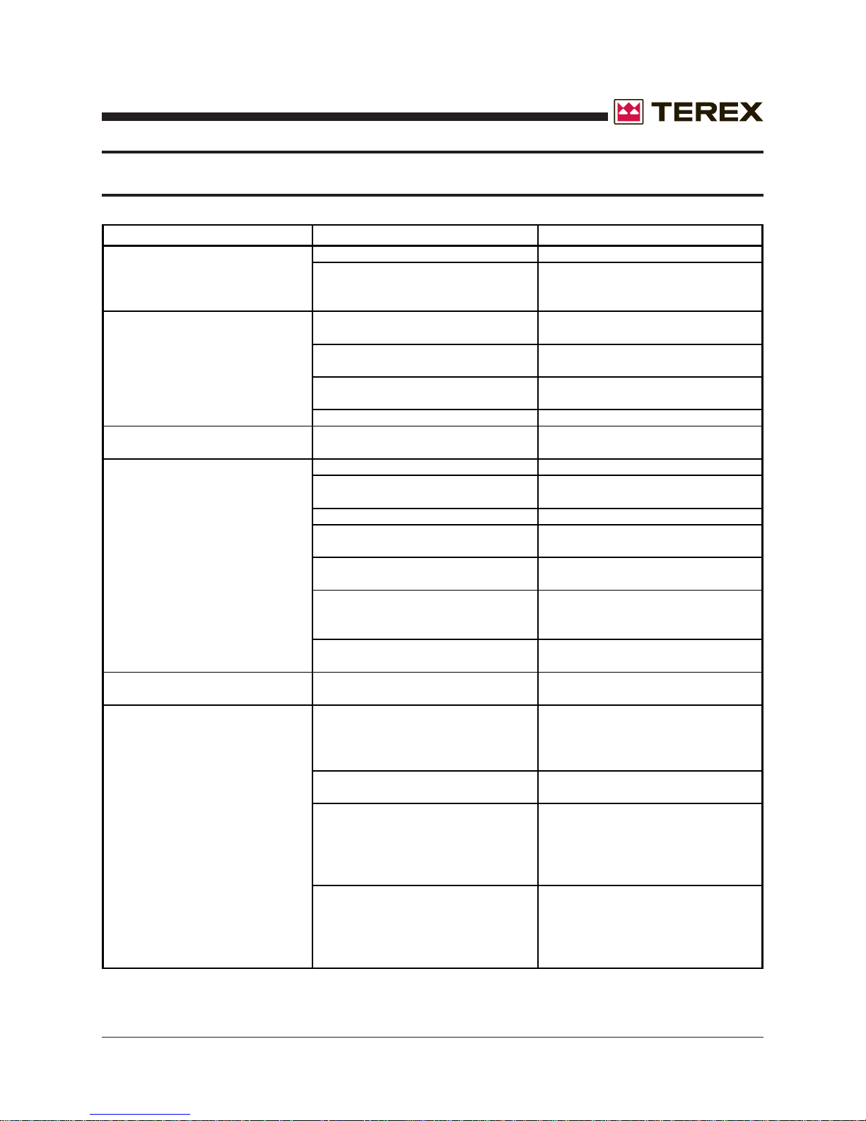
TROUBLESHOOTING
TROUBLE POSSIBLE CAUSE REMEDY
6.Engine runs but produces a a.Crankcase oil level is too high a.Drain oil to its proper level
dense smoke b.Low compression b.Have a trained mechanic
inspect for broken or s e ized
rings. Inspect valve clearances
7.Engine overheats a.Blocked cooling air intakes a.Inspect the front and rear intakes
and clear as needed
b.Low coolant levels b.Replace the coolant with a 50%
water/coolant solution
c.Radiator fins have become c.Clear the radiator fins
clogged
d.Fan belt is loose d.Tighten fan belt
8.Engine runs but the battery a.Alternator has failed a.Have a trained mechanic inspect
voltage is low the alternator
9.Engine runs but the lights will a.Circuit breakers are tripped a.Reset the circuit breaker
not operate b.Loose connections in the wiring b.Have a trained electrician inspect
system the ballast box wiring system
c.Burned out bulb c.Replace the bulbs as needed
d.Defective capacitor d.Have a trained electrician inspect
(Leroy Somers Generator) the capacitor
e.Defective AC generator e.Have a trained electrician inspect
the generator
f.Engine speed is too low f.Have a trained mechanic inspect
the engine speed and reset to
1800rpm @ 60hz
g.Defective ballast and capacitors g.Have a trained electrician inspect
the ballast and capacitors
10.Unusual noise coming from a.The generator has a defective a.Have a trained electrician inspect
the generator bearing or damaged fan blade the generator
11.Lamp will not start a.Lamp loose in socket a.Inspect lamp base to see if there
is arcing at center contact button.
Tighten lamp. Check socket for
damage. Replace if needed.
b.Floodlight plugs not tight
c.Defective ballast c.Interchange ballast plugs. If lamp
d.Low voltage d.Check line voltage at ballast input.
b.Check plug and receptacle. Tighten
if needed. Make sure power is off.
starts, replace ballast. Chec k for
swollen capacitors, charred wiring,
core and coil, or other signs of
excessive heat.
Voltage should be within 10% of
rating when operating at normal load.
Increase supply voltage or remove
external load.
Part No. 833002 Rev A AL4000 Light Tower 29
Page 30
November 2006
p
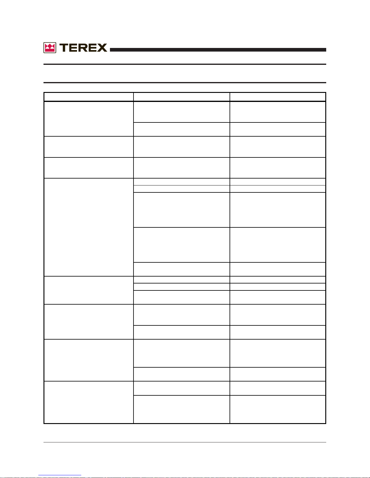
TROUBLESHOOTING
TROUBLE POSSIBLE CAUSE REMEDY
11.Lamp will not start e.Improper ballast e.The ballast name plate data should
agree with the line voltage and lamp
used. If not, replace the ballast.
f.Lamp has been operating; cool f.Switch off breaker and allow lamp
down time insufficient to cool.
12.Lamp starts slowly (arc does a.Defective lamp a.Lamp may glow for an extended
not strike when switch is first period of time. Replace after
turned on checking voltage and ballast
13.Circuit breaker trips on lamp a.Short circuit or ground a.Check wiring against diagram.
startup inspect for shorts or ground. Fix as
needed.
14.Lamp light output low a.Normal lamp depreciation a.Replace lamp
b.Dirty lamp or fixture b.Clean lamp and fixture
c.Defective ballast c.Interchange ballast plugs. If lamp
starts, replace ballast. Chec k for
swollen capacitors, charred wiring,
core and coil, or other signs of
excessive heat.
d.Wrong voltage d.Check line voltage at ballast input.
Voltage should be within 10% of
rating when operating at normal load.
Check wiring connections for voltage
loss. Check socket conta ct point.
e.Improper ballast e.Check ballast name plate against
lamp data
15.Lamp colors different a.Normal lamp depreciation a.Replace lamp
b.Dirty lamp or fixture b.Clean lamp and fixture
c.Wrong lamp c.Check data on lamps and replace
as needed.
16.Arc tube discolored or swollen a.Over voltage from power supply
b.Improper ballast b.Check ballast name plate against
17.Short lamp life a.Lamp damaged a.Check for outer bulb cracks,
b.Improper ballast b.Check ballast name plate against
18.Lamp flickers or goes out- a.Improper Ballast a.Check ballast name plate against
intermittent or cycling lamp data
b.New lamp
a.Check voltage at ballast, for current
or voltage surges, for shorted
capacitors and replace as needed
lamp data
cracks where lamp meets base, and
for broken arc tube or loose metal
parts. Replace as needed.
lamp data
b.Under certain conditions new lamps
may "cycle". Usually after 3 tries to
start at 30 to 60 second interval s,
will stabilize and operate normal
lam
30 AL4000 Light Tower Part No. 833002 Rev A
Page 31
November 2006
q
TROUBLESHOOTING
TROUBLE POSSIBLE CAUSE REMEDY
18.Lamp flickers or goes out- c.Defective lamp c.Replace lamp
intermittent or cycling d.High spike ballast
IF YOU FEEL AN ELECTRIC SHOCK AT ANY TIME WHILE
OPERATING THIS UNIT, SHUT IT DOWN IMMEDIATELY! HA VE
THE UNIT INSPECTED BY A TRAINED ELECTRICIAN.
d.Ballast produces high spike current.
Measure with oscilloscope. Replace
ballast as re
uired.
LIGHT FIXTURE TROUBLESHOOTING
DO NOT OPEN FIXTURES WHILE LIGHT CIRCUIT BREAKER
IS “ON”. ALLOW LAMP TO COOL BEFORE TOUCHING.
**TAKE EXTRA PRECAUTIONS WHEN TROUBLESHOOTING ELECTRICAL PROBLEMS**
A. Only use a voltmeter with two well-insulated pin probes rated for 600 volts.
B. Treat all conductors as potentially hot.
C. Proceed through circuits systematically, operating only one section at a time.
D. Before disconnecting ballast, turn off circuit breaker and wait 30 seconds for capacitor to
discharge.
E. If all the lights are out and all the ballasts are receiving power, suspect burned out power
cable.
Part No. 833002 Rev A AL4000 Light Tower 31
Page 32

November 2006
LIGHT FIXTURE TROUBLESHOOTING
TRACEABLE NUMBERED WIRING SYSTEM (Using plug-in ballasts to troubleshoot)
When troubleshooting the preceeding problems, minimize down time by following the traceable
numbered wiring system, always follow these steps:
STEP1: Ensure all ballasts, which are numbered, are plugged into lead wires with corre-
sponding numbers.
STEP 2: Looking at the lights from the glass side and following the diagram below, plug
each fixture into the appropriately numbered plug at the top of the tower.
By adhering to the traceable numbered wiring system, troubleshooting, fixture aiming, and fixture
control will follow a standard predictable pattern.
32 AL4000 Light Tower Part No. 833002 Rev A
Page 33

November 2006
WARRANTY
WARRANTY PROCEDURE
The specific language of this warranty will determine TEREX LIGHT CONSTRUCTION’s obligation in
connection with its product. The information presented below should be used as a general guide for implementation of policy . In the event of a component failure during the warranty period it should be repaired as
soon as possible, preferably at an authorized TEREX LIGHT CONSTRUCTION service center . If component
is manufactured by a company other than TEREX LIGHT CONSTRUCTION, such as Deutz, Honda, Isuzu,
Kubota, Leroy Somer , Lister Petter, Lombardini, Wisconsin, etc., the applicant should pursue rep air and/or
reimbursement through that manufacturer, and it s dealer/distributor network.
T o file a claim with TEREX LIGHT CONSTRUCTION, an APPLICA TION FOR W ARRANTY ADJUSTMENT
(AWA) form must be completed in it’ s entirety. Return the completed form within fourteen days of the
repair to:
A TTENTION: WARRANTY
TEREX LIGHT CONSTRUCTION
590 Huey Road
Rock Hill Industrial Park
Rock Hill, SC 29730
TEREX LIGHT CONSTRUCTION will review the AW A form. Should we desire to inspect the defective p arts,
we will issue you a return authorization for the defective parts. After inspecting the defective part(s), and it
is determined that warranty is due, we will then, at the discretion of TEREX LIGHT CONSTRUCTION ,
credit the applicants account or send replacement parts.
TEREX LIGHT CONSTRUCTION warranty reimbursements:
1. $40.00 for each hour’s labor we allow toward a repair.
2. Distributors cost of parts not more than the price currently available from TEREX LIGHT
CONSTRUCTION.
3. One way surface freight charges on parts returned to TEREX LIGHT CONSTRUCTION.
Many repairs are assigned a predetermined labor schedule which is an average time in which a skilled
technician should be able to make a repair . TEREX LIGHT CONSTRUCTION will reimburse not to exceed
the predetermined number of hours for a particular repair .
TEREX LIGHT CONSTRUCTION does not reimburse for:
1. Travel, travel time, nor travel labor.
2. Mileage.
3. Excessive diagnostic time.
4. Repairs of defects, malfunctions, or failures resulting from accidents, abuse, misuse, modifications, alterations, improper servicing or lack of performance of required maintenance service.
5. Repairs where defective parts were not shipped back when requested by TEREX LIGHT CONSTRUCTION.
6. Regular maintenance such as parts or labor for oil changes, filter changes or filters.
7. Repairs where defective parts were not received by TEREX LIGHT CONSTRUCTION after TEREX
LIGHT CONSTRUCTION issued a return authorization.
P.O.Box 3147• Rock Hill, S.C. 29731 USA • Phone 803-324-3011 • Fax 803-366-1 101
Part No. 833002 Rev A AL4000 Light Tower 33
TEREX Light Construction
Page 34

November 2006
WARRANTY
TEREX LIGHT CONSTRUCTION
P.O. Box 3147
Rock Hill, S.C. 29732
MANUFACTURER’S LIMITED WARRANTY
TEREX LIGHT CONSTRUCTION (“TLC”) warrants to the original purchaser that such equipment,
accessories, parts and other products manufactured by TLC will be free from defects in workmanship and
material for a period of one (1) year after the date of first delivery or for two thousand (2,000) hours of use,
whichever comes first; provided that Buyer sends TLC notice of such defect within thirty (30) days of its
discovery. Should defects be discovered, the Buyer must clearly establish that (I) the equipment, parts,
etc. have been properly installed and set up, maintained and operated within the limits of rated and normal
usage and (II) the defect did not result in any manner from the intentional or negligent action or inaction of
Buyer. Buyer must also return the defective item or items to TLC, Rock Hill, SC for inspection at TLC’s
request. If Buyer cannot establish that conditions (I) and (II) have been met, then this warranty shall not
cover the alleged defect. Failure to give notice of defect within such period shall be a waiver of this
Warranty and any assistance rendered thereafter shall not extend or revive it. THIS WARRANTY IS
LIMITED TO THE BUYER AND IS NOT ASSIGNABLE OR OTHERWISE TRANSFERABLE.
TLC MAKES NO WARRANTY WITH RESPECT TO PARTS, COMPONENTS, EQUIPMENT AND
ACCESSORIES NOT MANUFACTURED BY TLC SUCH AS FIXTURES, BALLASTS, ENGINES,
HYDRAULIC PUMPS, FUEL PUMPS, ALTERNATORS, GENERATORS, WINCHES, TIRES AND
ELECTRICAL COMPONENTS. Accessories, assemblies and components included in products of TLC,
which are not manufactured by TLC, are subject only to the warranty of their respective manufacturers.
TLC makes no other warranty, express or implied, and makes no warranty of merchantability or fitness for
any particular purpose. This warranty shall not cover misuse, alteration, abuse, negligence, accident, acts
of God, sabotage or any item in which serial numbers have been altered, defaced or removed, but shall be
limited to repair or replacement of those parts which, upon inspection by TLC, appear to have been
defective in material or workmanship.
TLC’s liability and Buyer’s sole and exclusive remedy for a failure of goods to perform as warranted and/or
for any and all other claims arising out of the purchase and use of the goods, including negligence on the
part of TLC, shall be limited to the repair or replacement of defective parts returned, transportation prepaid
to TLC. TLC shall in no event be liable for incidental or consequential or other damages or losses resulting
from a breach of warranty such as, but not by way of limitation, labor costs, loss of profits, loss of use of
other than equipment, third party repairs, personal injury, emotional or mental distress, improper
performance of work, penalties of any kind, loss of service of personnel, or any other damages or losses
which may be experienced by the Buyer.
A product warranty certificate must be filled out in its entirety and returned to TLC in order to
process any warranty claims submitted.
THIS WARRANTY IS EXPRESSLY IN LIEU OF AND EXCLUDES ALL OTHER WARRANTIES, EXPRESSED OR IMPLIED (INCLUDING ANY WARRANTY OF MERCHANTABILITY AND FITNESS OF
ANY PRODUCT OR GOODS FOR A PARTICULAR PURPOSE) AND ALL OTHER OBLIGATIONS OR
LIABILITIES ON TLC’S PART, AND TLC NEITHER ASSUMES NOR AUTHORIZES ANY OTHER PERSON TO ASSUME FOR TLC ANY OTHER LIABILITY IN CONNECTION WITH THE SALE OF TLC’S
PRODUCTS. THERE ARE NO WARRANTIES WHICH EXTEND BEYOND THE DESCRIPTION ON THE
FACE HEREOF.
34 AL4000 Light Tower Part No. 833002 Rev A
Page 35

November 2006
SERIAL NUMBER RECORD
TEREX LIGHT CONSTRUCTION
PORT ABLE LIGHT TOWER
OPERA TION AND SERVICE MANUAL
This Operation and Service Manual contains information pertaining to the operation and
maintenance of your Terex Light Tower. We suggest that you read this manual carefully prior
to operating the tower. This manual should be retained and referred to for operation, maintenance, and ordering parts. When ordering parts, PLEASE INCLUDE THE MODEL AND SERIAL
NUMBER located on the nameplate of the tower.
For major repair and service or other information, contact your local Terex dealer or write to:
T erex Light Construction
P.O. Box 3147
590 Huey Road
Rock Hill, SC 29730
T elephone: (803) 324-3011
FAX: (803) 366-1 101
When returning parts for credit please contact the factory for Return of Goods Authorization.
T erex Model Number _______________________ Serial Number ____________________
Engine Model Number _______________________ Serial Number ____________________
Generator Model Number ____________________ Serial Number ____________________
Sold to: _____________________________ Ship to: _________________________
_____________________________ _________________________
_____________________________ _________________________
Options: _____________________________ Production Date: _________________
_____________________________ Work Order Number ______________
_____________________________ Shipping Date ___________________
_____________________________ In Service Date __________________
_____________________________
_____________________________
When this unit left the factory the engine was filled with engine oil grade __________
Part No. 833002 Rev A AL4000 Light Tower 35
Page 36
MODEL NUMBER IDENTIFICATION
November 2006
36 AL4000 Light Tower Part No. 833002 Rev A
Page 37

November 2006
RECOMENDED ENGINE OIL & FUEL
KUBOTA D1105 DIESEL ENGINE
Engine oil should be MIL-L-2104C or have properties of API classification of CD grades or
higher. Change the type of engine oil according to the ambient operating temperature:
Above 77°F (25°C) SAE 30
32°F to 77°F (0 to 25°C) SAE 20
Below 32°F (0°) SAE 10W
SAE 10W-30
**Use #2 diesel fuel.**
NOTES:
1. The temperatures in the table are the ambient temperatures at the time when the engine
is started. If the running ambient temperatures are much higher than the starting temperatures, a compromise must be struck and a higher viscosity oil used. Multi-grade oils
overcome the problem, provided they possess a suitable specification.
2. MIL-L-2104B or MIL-L-2104C or API CD must also be used if the sulfur content of the fuel
exceeds 0.5%.
3. Always use a reputable brand of diesel fuel. The sulfur content should be below 0.5%
(higher sulfur content would require more frequent oil changes). Observe strict cleanliness when filling the fuel tank.
4. Check the engine oil level before starting the engine or more than five minutes after it
has been stopped. Remove the dipstick, wipe clean, reinsert it, take it out again, and
check the oil level. If the oil level is too low, remove the oil filler cap and add new oil until
the FULL line on the dipstick is reached.
Part No. 833002 Rev A AL4000 Light Tower 37
Page 38
November 2006
WIRE ROPE REPLACEMENT
CRITERIA FOR REPLACEMENT OF WIRE ROPE – TEREX LIGHT TOWERS
The wire ropes used to raise and lower the masts on a TEREX Light Tower are probably some of
the most important mechanical parts used in day-to-day operation of the machinery. It is therefore very important that the cables be inspected on a frequent basis (once a month) for wear and
tear, and immediately in the event of possible damage due to operator error in using the winch, or
possible damage from other equipment.
NORMAL WEAR AND TEAR
When used properly, the wire ropes should give years of trouble-free service, depending on how
often the masts are raised and lowered. The rule of thumb at TEREX is that if the tower is raised
and lowered an average of once per day, that the cables should be replaced every two
years of service.
NORMAL INSPECTION
The wire ropes are constructed of 7 strands of 19 plow steel wires each twisted together, and
then the assembly galvanized to resist corrosion. Using a wadded-up cloth or heavy leather
gloves (to avoid being pricked by a broken wire), run a hand up and down a length of the cable.
If any exterior wires are broken, they will lift up from main body of the cable and become visible.
For any given 1 foot of cable length; if there are 4 or more wires each, on any 2 or more strands
broken, the suspect rope should be replaced immediately.
DAMAGE INSPECTION
If any nicks (partial strand cut through), kinks (permanent bends), or weld spatter on the cable
(from field service) are observed, the suspect wire rope should be changed immediately. If
there is a crushed spot somewhere on the wire rope, it should be replaced only if the width of
the crushed spot exceeds 1-1/4 times the nominal diameter of the cable (5/16” on a 1/4” cable,
and 7/32” on a 3/16” cable), or if there are broken wires at the point of damage.
38 AL4000 Light Tower Part No. 833002 Rev A
Page 39

November 2006
WIRE ROPE REPLACEMENT
BROKEN CABLE REPLACEMENT PROCEDURE
1. PREPARATION
1.1 Collapse tower to where mast is retracted, then pivot tower to horizontal position.
1.2 Remove the tower from the trailer and place it on a work surface such as two saw horses.
2. REMOVING TOP CABLE AND TOP MAST SECTION
2.1 Tie middle section and large section together by wrapping band, cable, chain, or rope around
the sheave brackets on these two sections. This insures that the middle section stays inside
the large section during removal of the small section.
2.2 Remove or lock the telescope lock pin open. This is the pin that locks the three sections
together during travel.
2.3 Drill out the aluminum pop rivets holding the plastic guides at the top of the middle section.
Using a screwdriver, remove these guides.
2.4 Remove the clevis pin anchoring the cable to the top of the middle section and remove the
clevis pin and the sheave from the middle section.
2.5 Pass the free end of the cable through the sheave slot between the middle and small section,
and out of the top of the tower. Pull the cable and the small section completely out of the
middle section together. Be sure to keep the cable tight; if slack accumulates it is most
difficult to remove.
2.6 Unfasten the cable by removing the bolt at the base of the small section.
3. REINSTALLING THE SMALL SECTION
3.1 Fasten new cable to the base of the small section.
3.2 Reversing the procedure described in steps 2.1 through 2.5, reinstall the small section.
3.3 Reinstall the plastic guides with new pop rivets. New plastic guides should be used, but the
old guides can be used if their mounting position is shifted to the point where new holes can
be drilled in the tower section to provide a good fit when installing new pop rivets.
4. REMOVING THE LOWER CABLE AND MIDDLE TOWER SECTION
4.1 Remove or lock open the telescope lock pin if not previously done in step 2.2.
4.2 Drill out the aluminum pop rivets holding the plastic guides at the top of the large section.
Using a screwdriver, remove these guides.
4.3 Remove the cable from winch drum.
4.4 Remove the sheave clevis pin and the sheave from the top of the large section.
4.5 If the old cable is not frayed between the winch and the bottom mast pulley, attach a flexible
“fish wire” or “snake” (wire, rope cord, etc.) to the end of the cable to be used to thread the
new cable through the lower tower and pulleys. This can be done by “untwisting” the cable
and inserting the wire or cord into the middle of the cable and thus letting the cable twist
back tightly around the fish wire. If the old cable is frayed, cut off the frayed portion and
proceed as above and then remove tower and cable as instructed in section 4.6.
Part No. 833002 Rev A AL4000 Light Tower 39
Page 40

WIRE ROPE REPLACEMENT
4.6 Pass the free end of the cable through the sheave slot between the large and middle sections
and out of the top of the tower. Pull the cable and the middle section completely out of the
large section altogether. Be sure to keep the cable tight, if slack accumulates it is most
difficult to remove.
4.7 If the fish wire doesn’t work, it is necessary to remove the square mast section from the
round mast section. Remove the pivot pin from the pivot post and lift the mast from the pivot
post and place the assembly on a work surface. Remove the hex nut from the bottom of the
round section, remove the “T” bolt at the top of the round section, and pull the square mast
assembly out of the round section, and proceed as instructed in section 4.6.
4.8 Unfasten the cable by removing the bolt at the base of the middle section.
5. REINSTALLING THE LOWER CABLE AND MIDDLE SECTION
5.1 If the “fish wire” worked, attach the cable to the fish wire and pull through the pulleys and the
round section.
5.2 If the square tower section was removed from the round section, thread the cable through the
pulleys at the bottom of the large section and out of the tubular stud. Reinstall the large
square section into the round section. Install the “T” locking bolt, and the hex nut on the
bottom of the round section. The hex-locking nut should be tightened and then backed off
approximately one-half turn or until the tower rotates freely.
5.3 Fasten the new cable to the base of the middle section.
5.4 Reversing the procedures detailed in sections 4.4 through 4.7, reinstall the middle section.
5.5 Fasten the new cable to the winch drum.
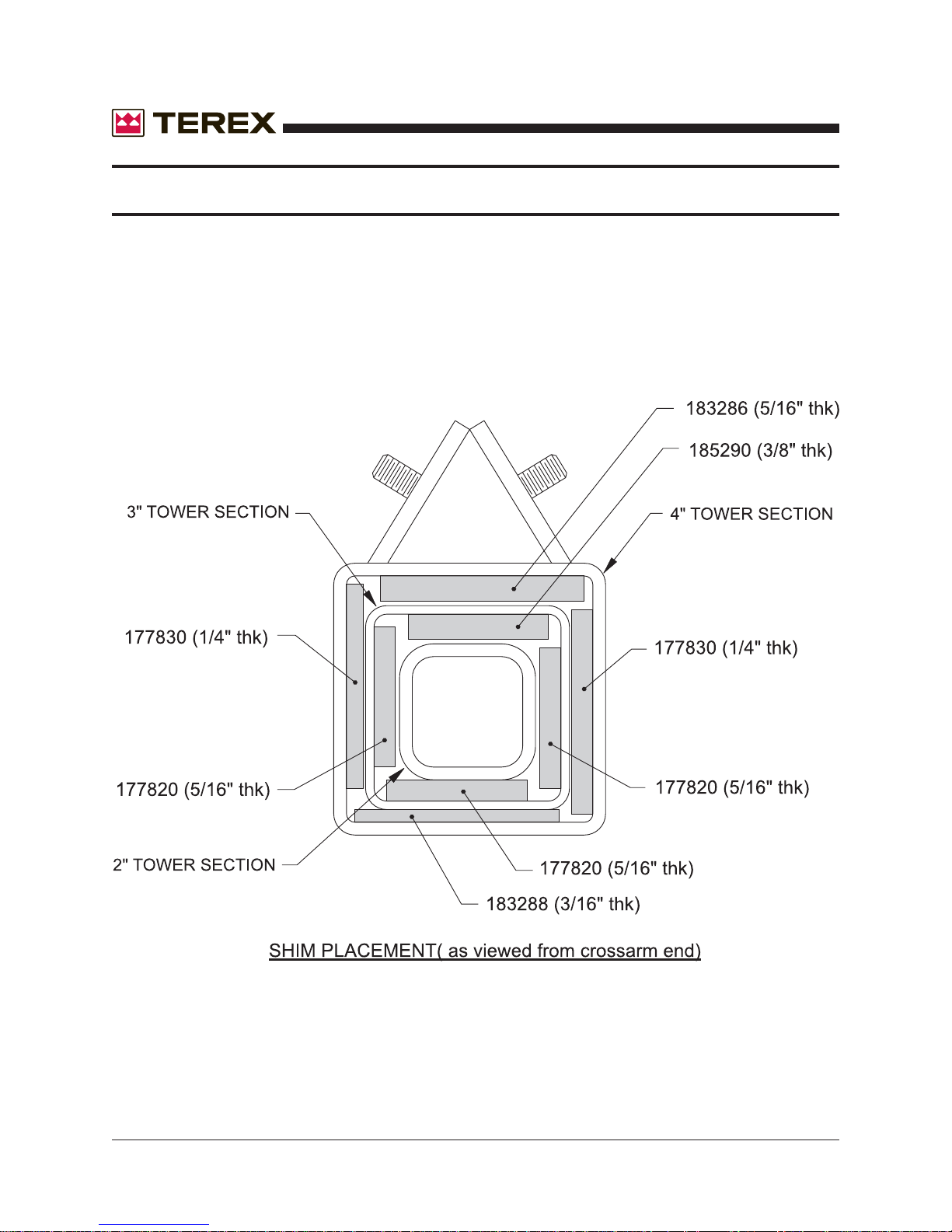
5.6 Reinstall the plastic shims as described in section 3.3.
November 2006
40 AL4000 Light Tower Part No. 833002 Rev A
Page 41
November 2006
WIRE ROPE REPLACEMENT
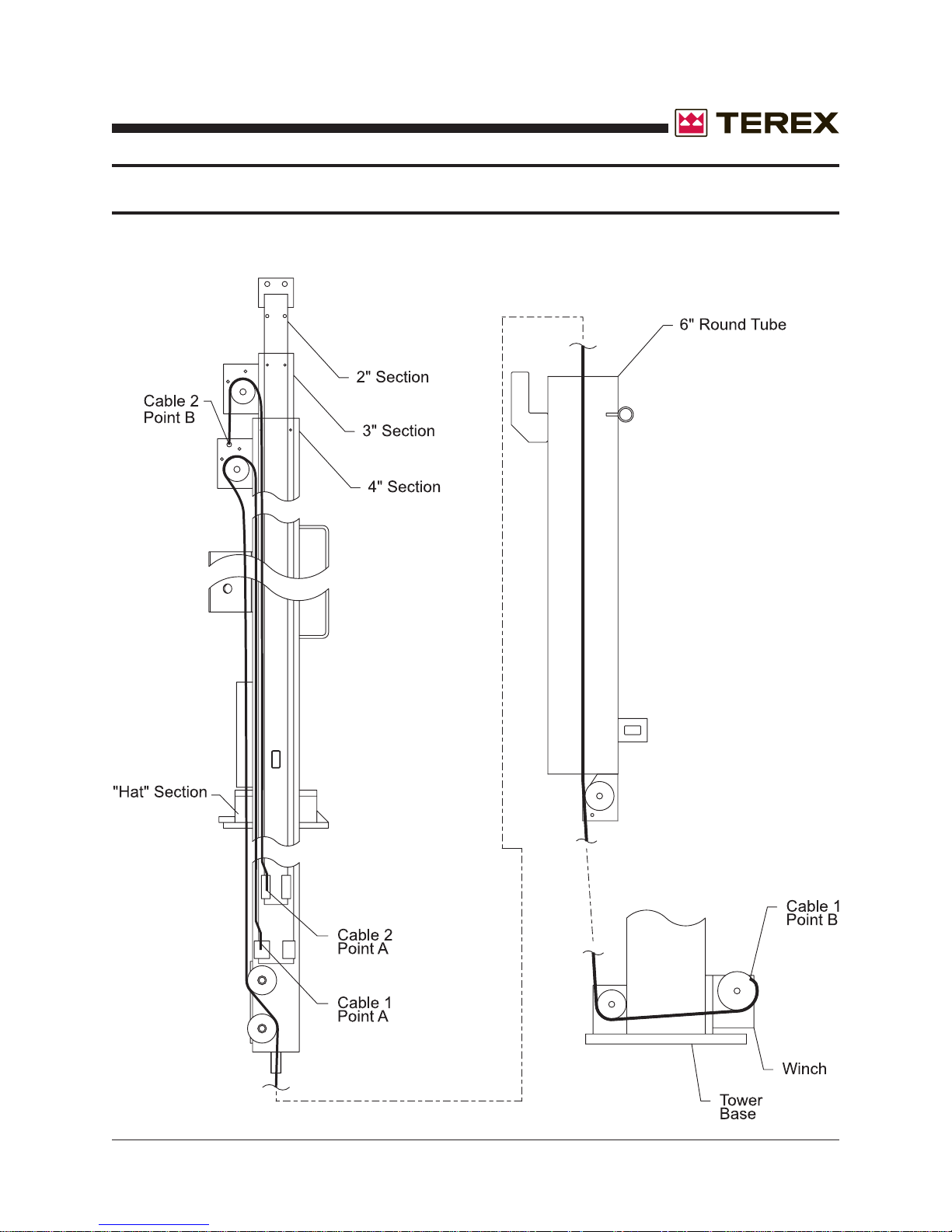
Cable Replacement Diagram
Part No. 833002 Rev A AL4000 Light Tower 41
Page 42
WIRE ROPE REPLACEMENT
Tower Shim Placement
November 2006
42 AL4000 Light Tower Part No. 833002 Rev A
Page 43

November 2006
Wiring Diagrams
Section
Part No. 833002 Rev A AL4000 Light Tower 43
Page 44
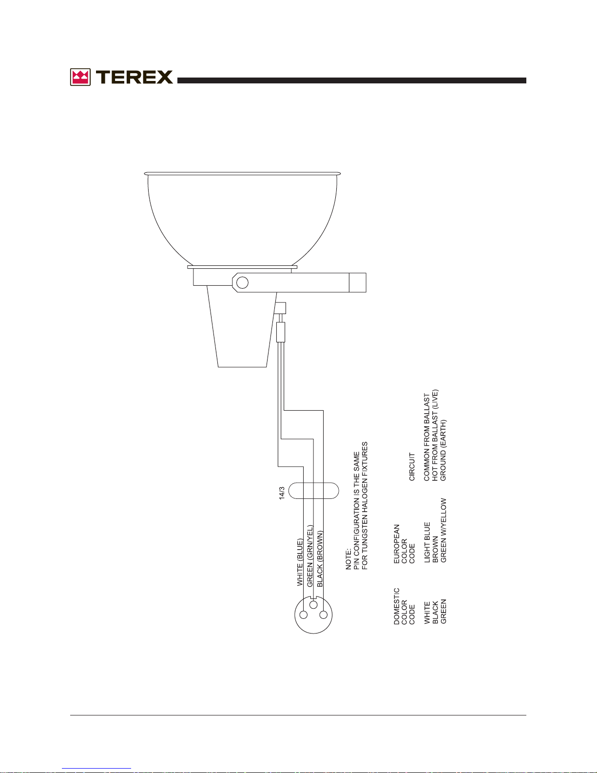
Fixture Wiring Diagram
November 2006
44 AL4000 Light Tower Part No. 833002 Rev A
Page 45
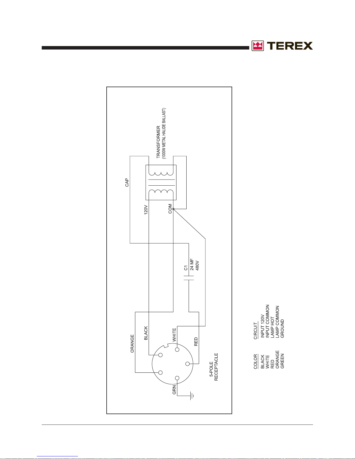
November 2006
1000MH Ballast Diagram
Part No. 833002 Rev A AL4000 Light Tower 45
Page 46
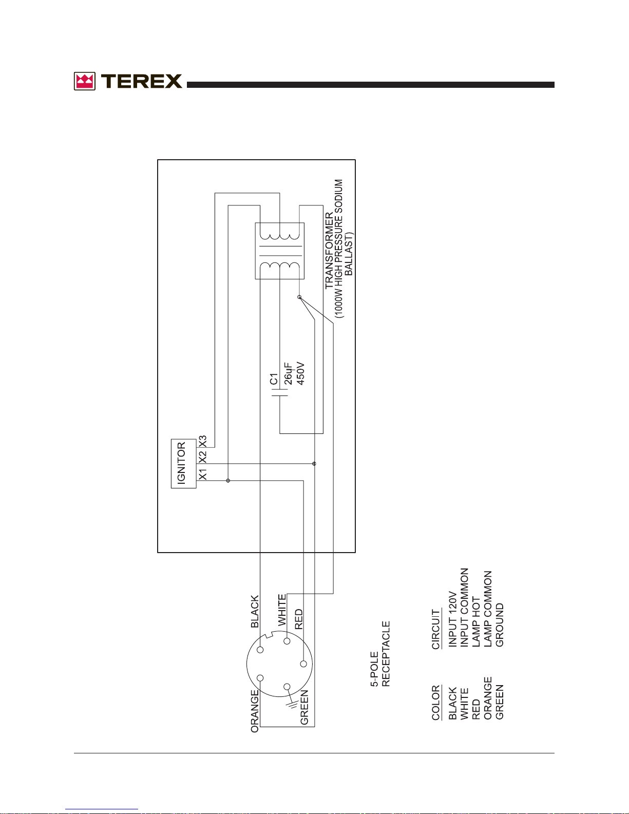
1000HPS Ballast Diagram
November 2006
46 AL4000 Light Tower Part No. 833002 Rev A
Page 47
November 2006
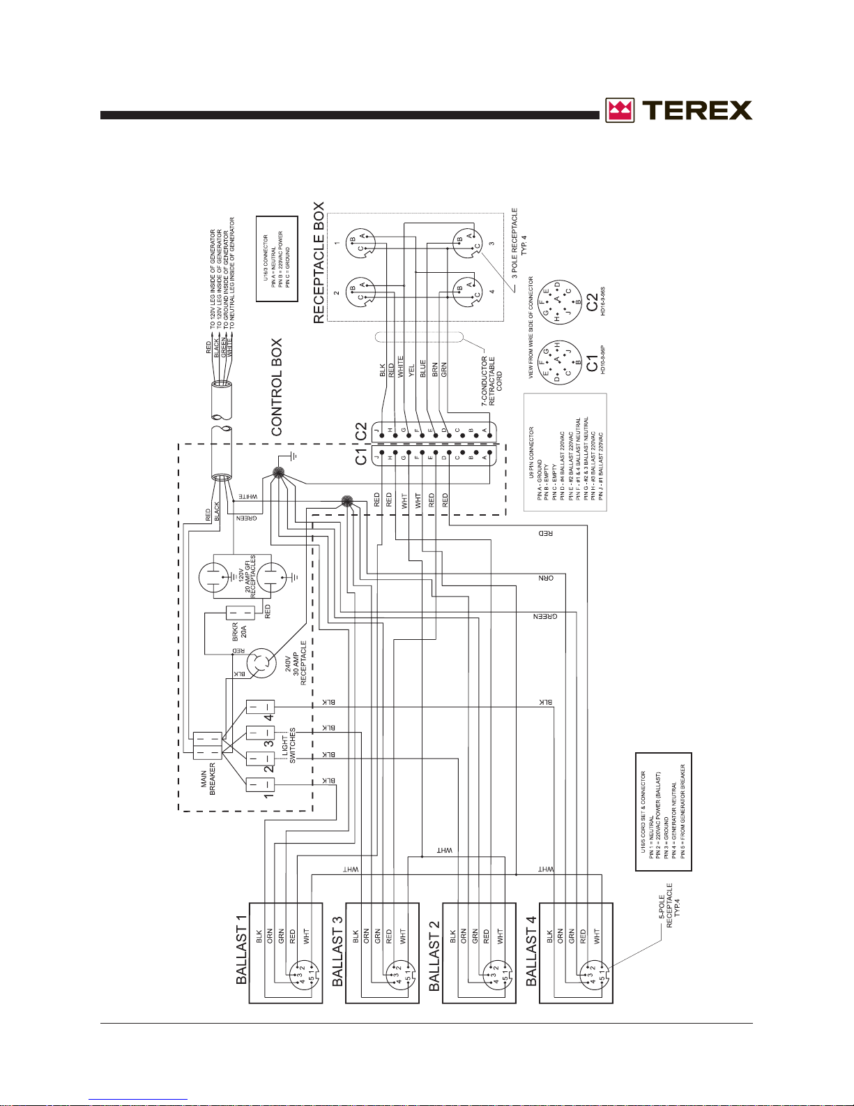
AC Wiring For A Light Tower Diagram
Part No. 833002 Rev A AL4000 Light Tower 47
Page 48
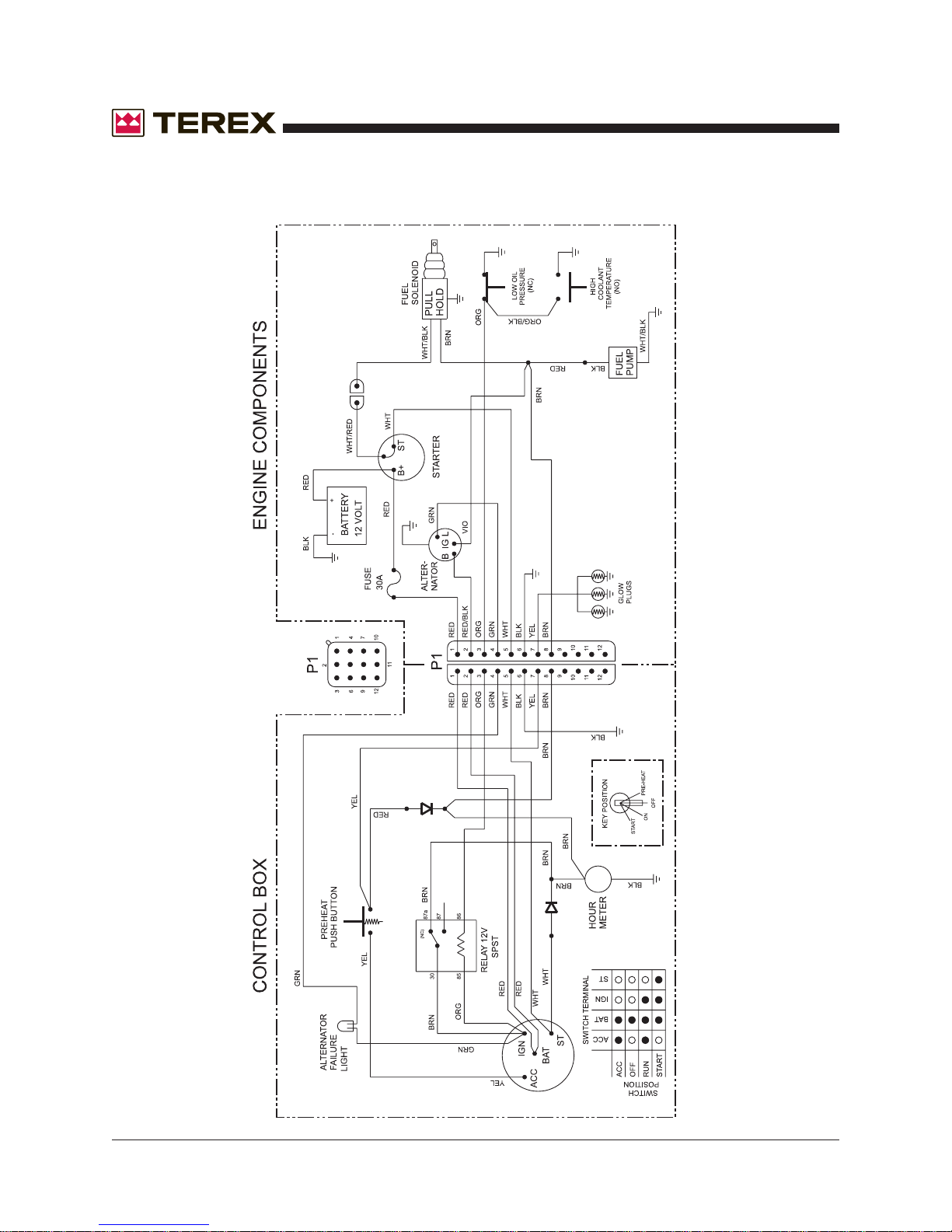
DC Engine Wiring Diagram
November 2006
48 AL4000 Light Tower Part No. 833002 Rev A
Page 49
November 2006
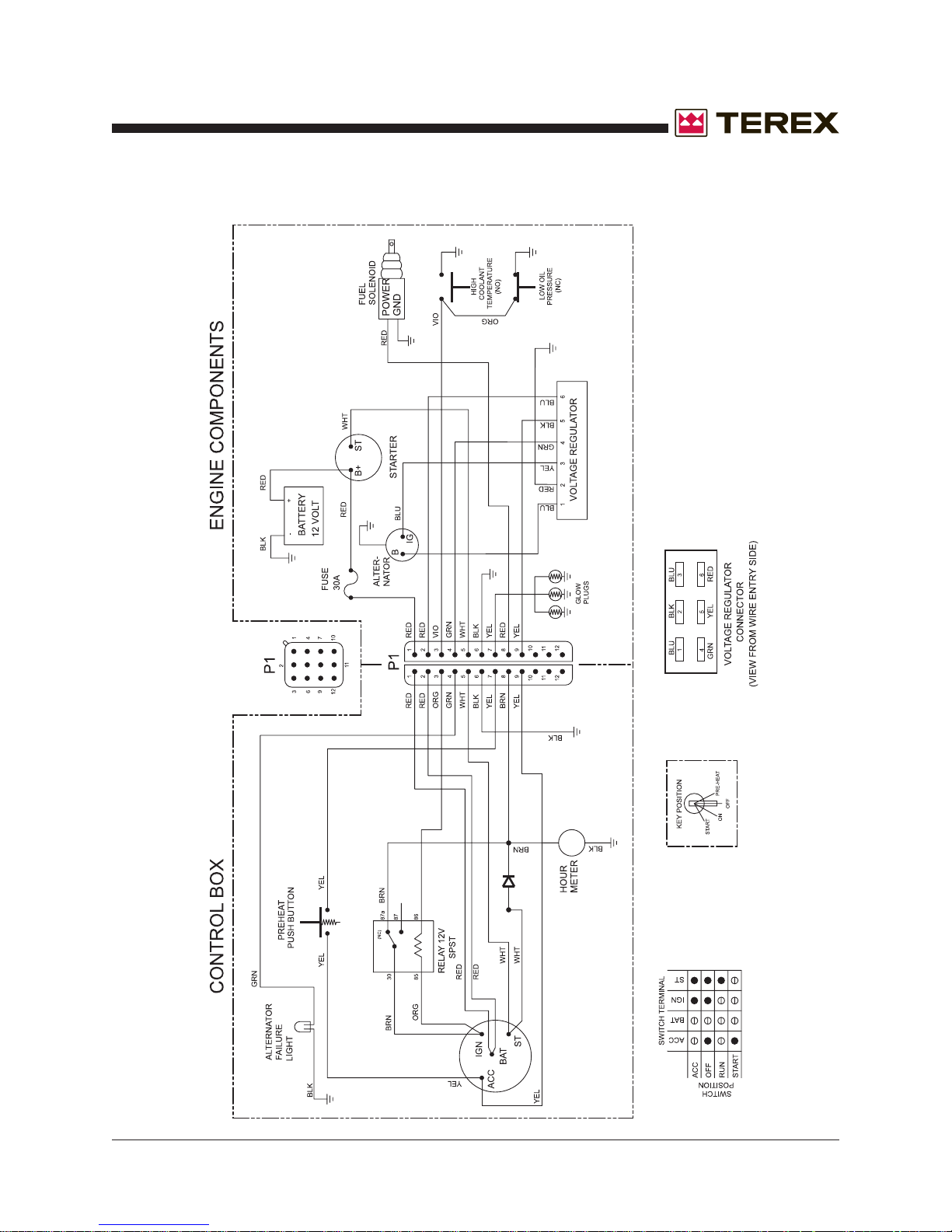
AC Light Tower Wiring Diagram - Perkins
Part No. 833002 Rev A AL4000 Light Tower 49
Page 50
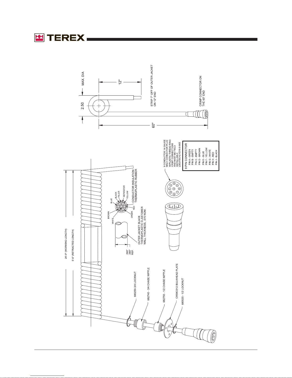
Consolidated Coil Cord With Plug End
November 2006
50 AL4000 Light Tower Part No. 833002 Rev A
Page 51

November 2006
Parts Catalog
Section
Part No. 833002 Rev A AL4000 Light Tower 51
Page 52
November 2006
GENERAL INFORMATION-PARTS MANUAL
INTRODUCTION
This manual contains parts ordering information for the Terex AL 4000 light tower.
IDENTIFICATION of PARTS
All parts are identified with a part number and brief description. If there are multiple quantities of the part
required, the quantity required will be shown along with part number and description. If no quantity is given
it is assumed that there is only one part required.
NOTES and DESIGNATIONS
This manual is compiled from information available and current at time of approval for printing. Terex
reserves the right to improve its product without notice to follow its policy of constantly striving to manufac-
ture a better product.
ILLUSTRATIONS
The illustrations in this manual are intended to show typical construction of the various parts. In some
instances the shapes or details of the parts illustrated may not exactly represent their actual appearance.
However, they will serve to show the servicing methods explained or help to identify parts performing the
same function.
52 AL4000 Light Tower Part No. 833002 Rev A
Page 53

November 2006
PARTS ORDERING INFORMATION
IMPORTANT
When a part fails and needs to be replaced, only use equivalent parts of equal performance and strength.
Contact your local Terex dealer for parts and service.
When ordering parts for a specific unit, follow the instructions listed below. By doing so, you will be assured
of receiving the correct part in the shortest period of time.
1. Send your order to the nearest Terex distributor in your area.
2. Give the light tower model and serial number.
3. Write the quantity required, part number, and description of the parts wanted.
4. Give the specific shipping instructions, to whom and where parts are to be shipped, also whether
shipment is to go parcel post, express freight, or truck, prepaid or collect. We want your order to reach
you as quickly and as economically as possible.
5. Confirm all telephone orders in writing via main or fax confirmation.
PART NUMBERS AND PRICES ARE SUBJECT TO CHANGE WITHOUT NOTICE.
Part No. 833002 Rev A AL4000 Light Tower 53
Page 54
November 2006
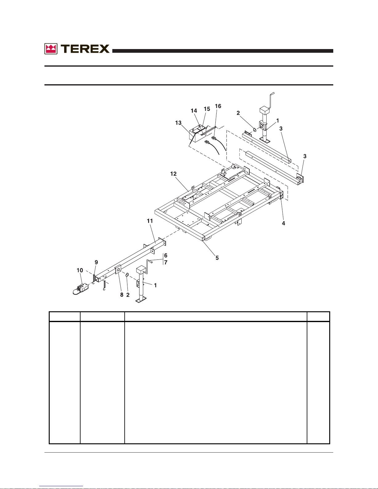
TRAILER FRAME/TONGUE/OUTRIGGERS
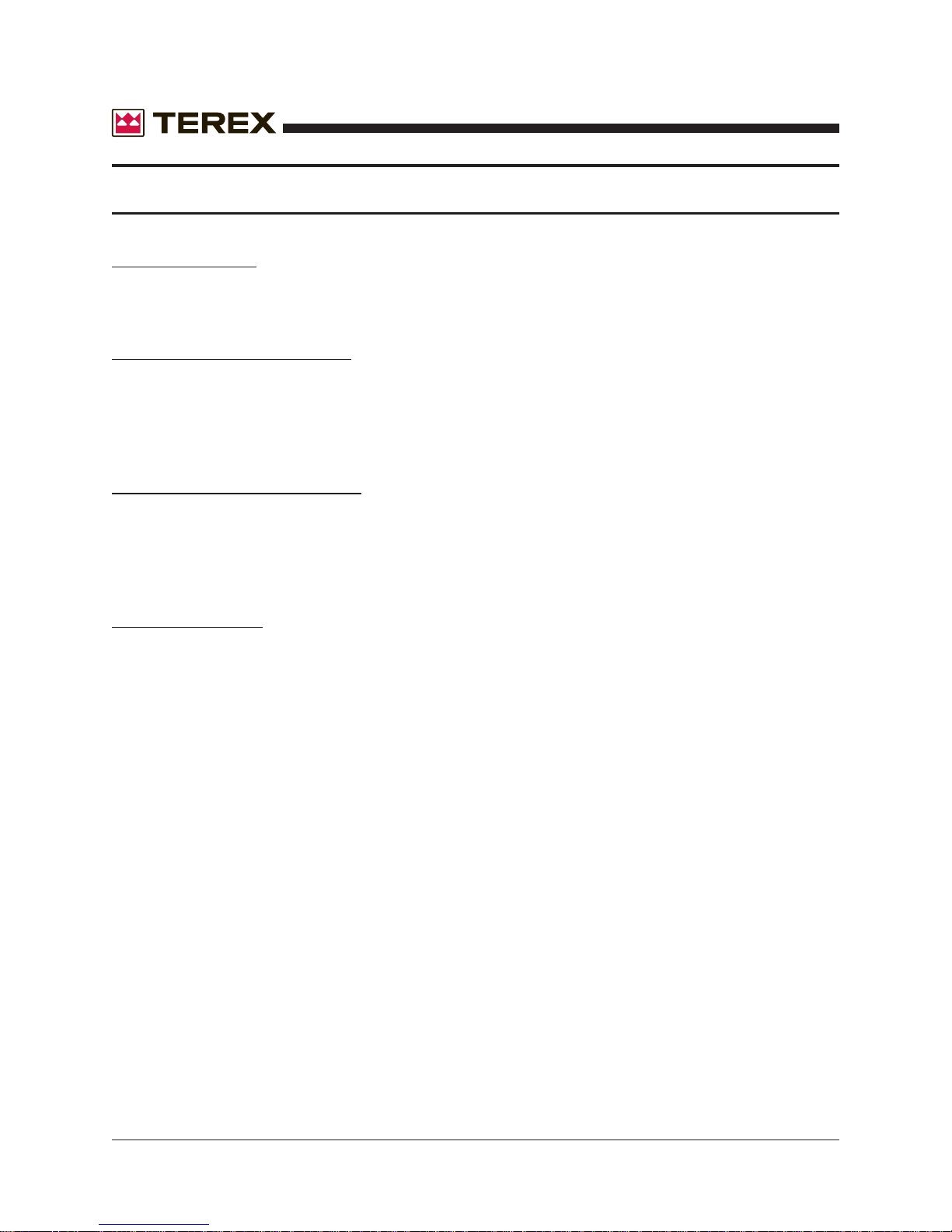
ITEM # PART # DESCRIPTION QTY.
1 841430 JACK SIDEWIND LONG 3KLB 3
2 840222 JACK SNAP RING 3
3 114480 OUTRIGGER 2X2X42 2
4 109150 KIT: OUTRIGGER PLUNGER PIN KIT 2
5 721051 CAPLUG,TUBE PLUG 2 1/2 4
6 834219 HANDLE (ARM)FOR JACK, HAMMERBLOW 3
7 834204 HANDLE (ARM)FOR JACK, FULTON 3
8 840221 JACK BRACKET SWIVEL 1
9 111936 CHAIN SAFETY 3000LB 3/8X30 W/"S"-HOOK 2
10 840120 COUPLER 2" BOLT ON 1
11 124470 TONGUE WITH JACK BRACKET 1
12 124410 TRAILER FRAME 41X70 WITHOUT AXLE 1
13 182330 BATTERY HOLD DOWN ROD 2
14 174170 BATTERY HOLD DOWN ANGLE 1
15 160110 BATTERY WET 12V GR24 525 CCA STD-DUTY LEAD ACID 1
16 160270 BATTERY CABLE SET 1
54 AL4000 Light Tower Part No. 833002 Rev A
Page 55
November 2006
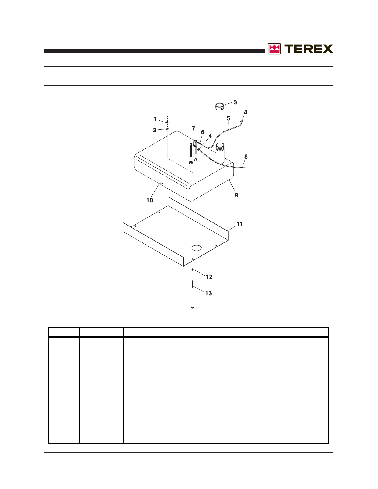
FUEL TANK
ITEM # PART # DESCRIPTION QTY.
1 990200 NUT LOCK NYLON INSERT 1/2-13NC GR 2 4
2 990210 WASHER FLAT 1/2 8
3 742240-1 TANK CAP NO-GAUGE 1
4 792750 CLAMP 7/16 TO 25/32 2
5 890795 HOSE,FUEL 5/16 ID AR
6 898590 HOSE FITTING,PIPE/BARB 1
7 891560 HOSE FITTING,PIPE/BARB 1
8 890785 HOSE,FUEL 1/8 ID AR
9 742220 TANK FUEL 30GAL 1
10 109505 KIT: FUEL TANK DRAIN PLUG REPLACEMENT 1
11 188630 FUEL TANK PAN 1
12 990210 WASHER FLAT 1/2 8
13 994650 SCREW,1/2-13NCX10 HHC GRADE2 4
Part No. 833002 Rev A AL4000 Light Tower 55
Page 56
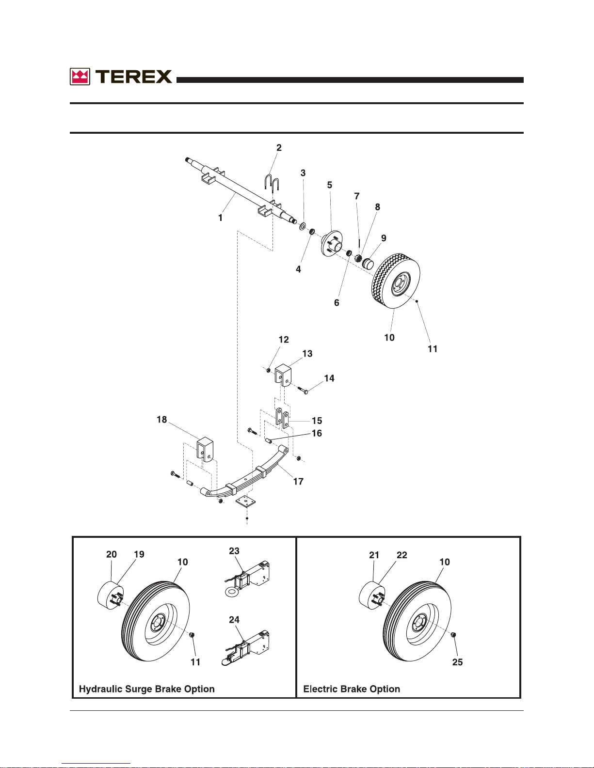
AXLE ASSEMBLY
November 2006
56 AL4000 Light Tower Part No. 833002 Rev A
Page 57
November 2006
ITEM # P ART # DESCRIPTION QTY.
1 841050 AXLE 3500LB 38.5 SPRING CENTER 1
2 834267 U-BOLT KIT - 3500# 2
3 834229 SEAL, HYDRAULIC 2
4 834226 INNER BEARING 2
5 834220 HUB ASSY HT1000 3500LB 2
6 834227 OUTER BEARING 2
7 834225 SEAL,GREASE 2
8 834250 SPINDLE NUT 2
9 834228 GREASE CAP 2
10 841060 TIRE & WHEEL MOUNTED P205/75-15 LOAD B2 2
11 840376 AXLE WHEEL NUT 10
12 840395 AXLE SPRING NUT 6
13 840392 AXLE REAR HANGER 2
14 840394 AXLE SPRING BOLT 6
15 841473 AXLE SHACKLE 2
16 834246 SPRING EYE BUSHING 4
17 834211 SPRING FOR AXLE 4-LEAF 2
18 841051 AXLE FRONT HANGER 2
19 841855 AXLE HUB,HYD. & PARK BRAKE,L/H 1
20 841860 AXLE HUB,HYD. & PARK BRAKE,R/H 1
21 841870 AXLE HUB,ELECTRIC&PARK BRAKE,LH 1
22 841875 AXLE HUB,ELECTRIC&PARK BRAKE,RH 1
23 841220 COUPLER,SURGE 3"RING 1
24 841500 COUPLER,SURGE,2"BALL 1
25 840396 AXLE WHEEL NUT 10
Part No. 833002 Rev A AL4000 Light Tower 57
Page 58
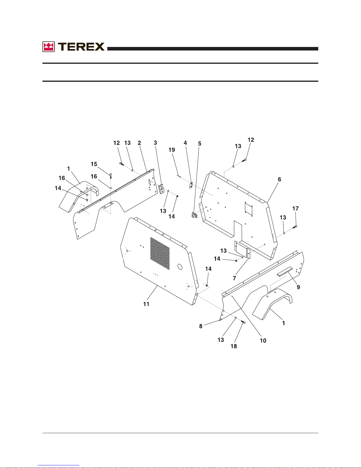
CABINET ASSEMBLY
November 2006
58 AL4000 Light Tower Part No. 833002 Rev A
Page 59
November 2006
ITEM # PART # DESCRIPTION QTY.
1 123490 FENDER WITH SKIRT 2
2 188570 CABINET SIDE PANEL ROADSIDE 1
3 184150 WINCH HANDLE BUSHING 1
4 796432 GAS SPRING SHORT BRACKET WITH BALL 8
5 124420 GROUND ROD STORAGE TUBE 1
6 188530-2 CABINET FRONT PANEL 1
7 176370 LITERATURE RACK 1
8 188580 CABINET SIDE PANEL CURBSIDE 1
9 930950 WEATHERSTRIP ADHESIVE AR
10 791840 BUMPER RUBBER 4
11 124430 CABINET REAR PANEL 1
12 994130 SCREW,1/4-20NCX1 4
13 993850 WASHER FLAT 1/4 37
14 990150 NUT LOCK NYLON INSERT 1/4-20NC GR 2 ZP 18
15 993440 SCREW 1/4-20NCX3/4 8
16 990340 WASHER FLAT 1/4 16
17 993421 SCREW,1/4-20NCX3/4 2
18 995810 SCREW,1/4-20NCX5/8,HWH 27
19 992040 RIVET POP 3/16X.602 16
Part No. 833002 Rev A AL4000 Light Tower 59
Page 60
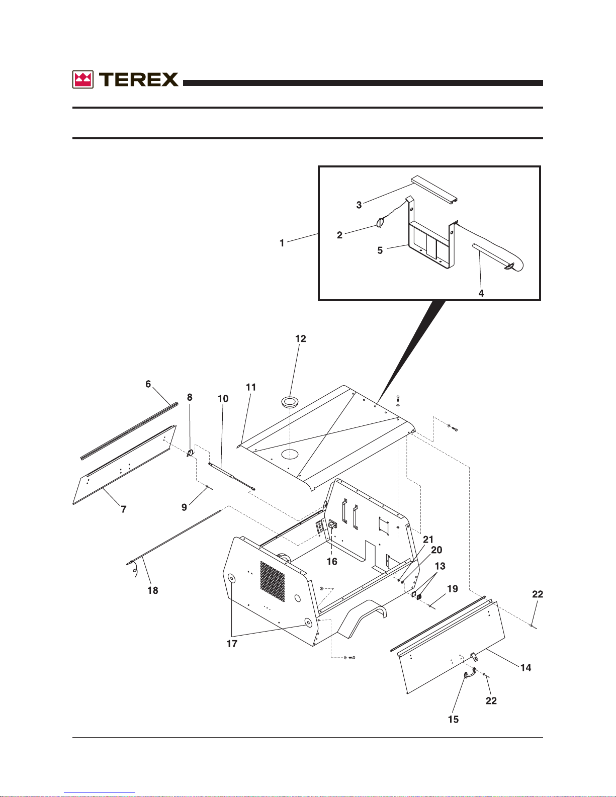
CABINET ASSEMBLY (TOP & DOORS)
November 2006
60 AL4000 Light Tower Part No. 833002 Rev A
Page 61
November 2006
ITEM # PART # DESCRIPTION QTY.
1 116180 REAR TOWER SUPPORT, COMPLETE ASSEMBLY 1
2 790540 PIN QUICK1/4X1.75 ZP 1
3 720220 BUMPER REAR TOWER SUPPORT 1
4 123680 PIN W/RING 3/4X11 1
5 124460 REAR TOWER SUPPORT 1
6 796610 HINGE PIANO 1.5X51.75 2
7 188560 CABINET DOOR PANEL 1
8 796432 GAS SPRING SHORT BRACKET WITH BALL 8
9 992040 RIVET POP 3/16X.602 16
10 796436 GAS SPRING 16", 60 LB. 4
11 188550-2 CABINET TOP PANEL 1
12 794940 PLUG PLASTIC 1
13 189796 HASP,CABINET DOOR, 2
14 188560 CABINET DOOR PANEL 1
15 790940 HANDLE 5.75 CHROME PLATED 2
16 124420 GROUND ROD STORAGE TUBE 1
17 176380 COVER PLATE,CABINET 2
18 113399 GROUND ROD LT.TWR. 1
19 995050 SCREW,#10-32NFX3/4 4
20 R980300 WASHER,FLAT,#10 4
21 995420 NUT,LOCK NYLON INSERT #10-32 HX M/S JAM 4
22 990670 RIVET POP 3/16X1/2 36
Part No. 833002 Rev A AL4000 Light Tower 61
Page 62
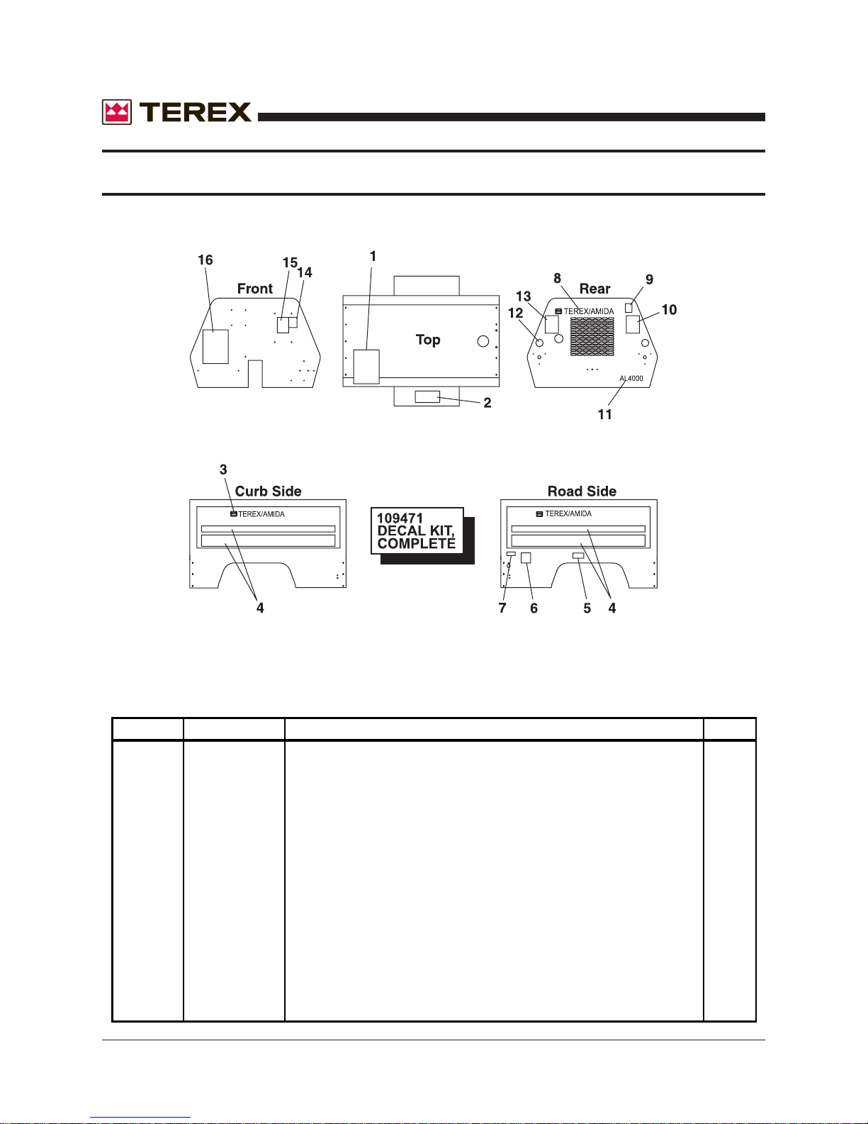
CABINET DECALS
November 2006
ITEM # PART # DESCRIPTION QTY.
1 850091 DECAL: DANGER CRUSH HAZARD 1
2 851640 DECAL: TOWER OPERATING INSTRUCTIONS 1
3 853296 DECAL: TEREX-AMIDA RED AND BLACK 5X29.5 2
4 853312 DECAL: STRIPING RED/BLACK 2
5 850155 DECAL: NO.2 DIESEL FUEL ONLY 1
6 850107 DECAL-CAUTION,WINCHLOCK SYSTEM 1
7 853640 DECAL: "CAUTION",WINCH ROTATION 1
8 853291 DECAL: TEREX-AMIDA RED AND BLACK 2.75X16 1
9 CU51A112 DECAL: DANGER HOT EXHAUST 1
10 850093 DECAL: DO NOT STAND BEHIND TOWER 1
11 853301 DECAL: AL4000 BLACK 2.2X9.5 1
12 841710 RED REFLECTOR 2
13 850092 DECAL: DANGER FALLING BOOM 1
14 853070 DECAL: CAUTION READ MANUAL 1
15 851860 DECAL: DANGER! ELECTRIC SHOCK HAZARD 1
16 852410 DECAL: OPERATING INSTRUCTIONS 1
62 AL4000 Light Tower Part No. 833002 Rev A
Page 63
November 2006
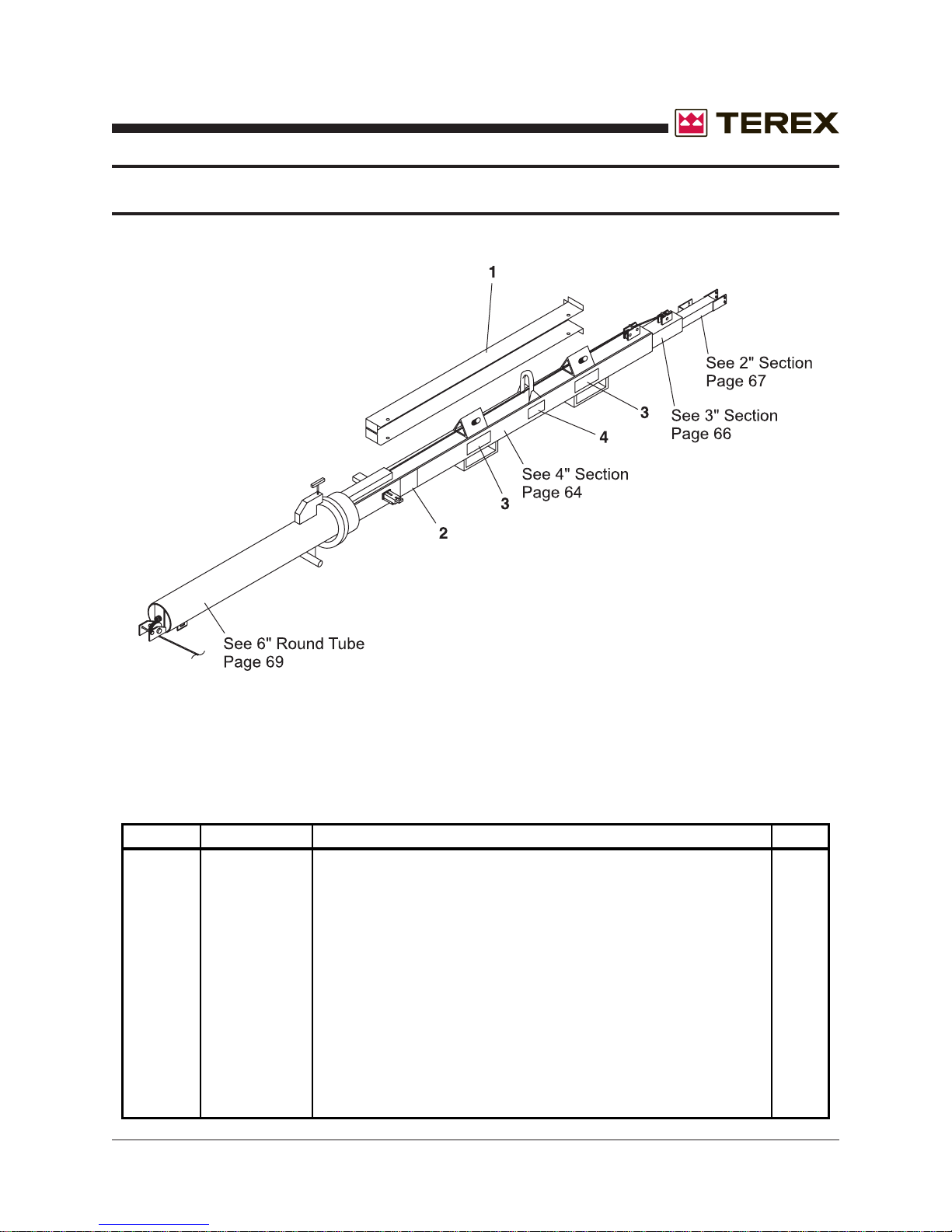
TOWER ASSEMBLY
ITEM # PART # DESCRIPTION QTY.
1 113080 COIL CORD SLEEVE 1
2 851545 DECAL: DANGER DO NOT RAISE TOWER IN VICINITY 1
3 R850475 DECAL: WARNING FORKS 2
4 851550 DECAL: LIFT MACHINE HERE 1
Part No. 833002 Rev A AL4000 Light Tower 63
Page 64
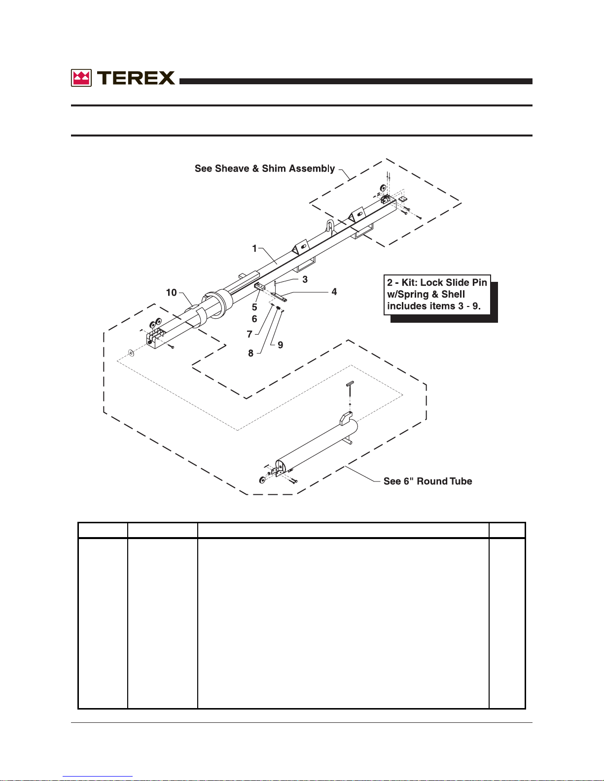
4” INCH TOWER SECTION
November 2006
ITEM # PART # DESCRIPTION QTY.
1 124540 4" SECTION 30'TOWER 1
2 109516 KIT:LOCK SLIDE PIN W/ SPRING & SHELL includes 3-9 1
3 990660 ROLL PIN 1/4 X1-5/8 1
4 113362 PIN,LOCK SLIDE,WITH RING includes 10-13 1
5 171635 LOCK PIN SHELL 1
6 171640 LOCK SPRING SHELL 1
7 980340 SCREW,5/16-18NCX1/2 HHCS, GR 2, ZP 1
8 790710 SPRING COIL 1/2 X2.25 1
9 990650 COTTER PIN 1/8X1 SS 1
10 177810 SHIM 3/16X2X19-3/4 1
64 AL4000 Light Tower Part No. 833002 Rev A
Page 65
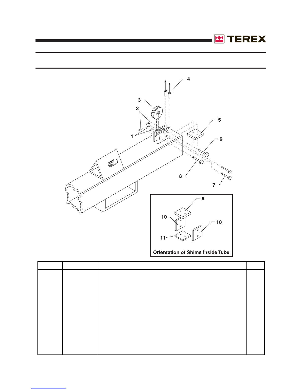
November 2006
4” TOWER SECTION (UPPER SHEAVE & SHIM)
ITEM # PART # DESCRIPTION QTY.
1 994920 COTTER PIN 3/32X3/4 SS 2
2 990650 COTTER PIN 1/8X1 SS 2
3 188760 SHEAVE 3-1/8 X1 1/4 CABLE 2
4 990670 RIVET POP 3/16X1/2 S/S BLIND RIVET 8
5 183286 SHIM 5/16X2X3-3/16 1
6 995780 CLEVIS PIN STAINLESS STEEL 3/8 X2 1
7 992765 CLEVIS PIN STAINLESS STEEL 1/2 X2 1
8 995790 CLEVIS PIN STAINLESS STEEL 1/4 X2 2
9 183286 SHIM 5/16X2X3-3/16 1
10 177830 SHIM 1/4X2X3-3/16 2
11 183288 SHIM 3/16X2X3-3/16 1
Part No. 833002 Rev A AL4000 Light Tower 65
Page 66
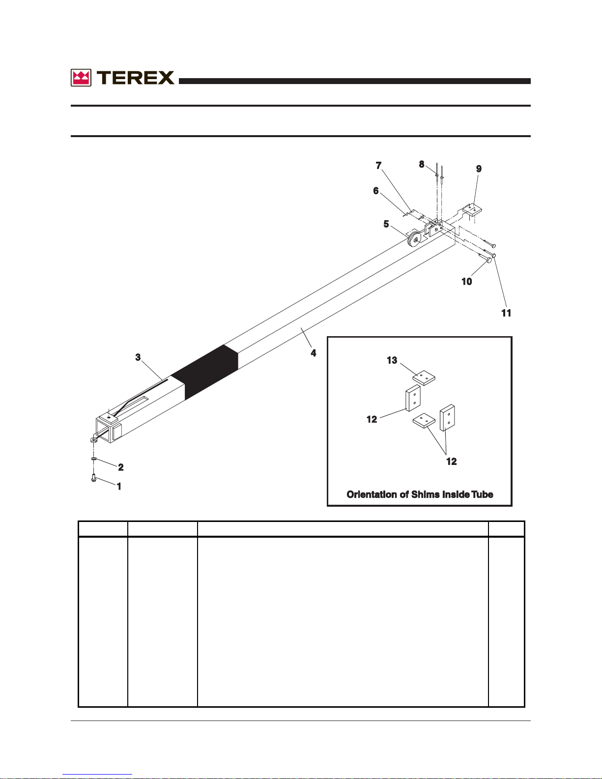
3” INCH TOWER SECTION
November 2006
ITEM # PART # DECSCRIPTION QTY.
1 996230 SCREW,3/8-16NCX7/8 1
2 990470 WASHER LOCK 3/8 1
3 109065 KIT: CABLE ASSEMBLY LOWER 1/4 CABLE 1
4 124550 3 SECTION 30'TOWER 1
5 188760 SHEAVE 3-1/8 X1 1/4 CABLE 1
6 990650 COTTER PIN 1/8X1 SS 1
7 994920 COTTER PIN 3/32X3/4 SS 2
8 990670 RIVET POP 3/16X1/2 S/S BLIND RIVET 8
9 185290 SHIM 3/8X2X2-1/4 1
10 992765 CLEVIS PIN STAINLESS STEEL 1/2 X2 1
11 995790 CLEVIS PIN STAINLESS STEEL 1/4 X2 2
12 177820 SHIM 5/16X2X2-1/4 3
13 185290 SHIM 3/8X2X2-1/4 1
66 AL4000 Light Tower Part No. 833002 Rev A
Page 67
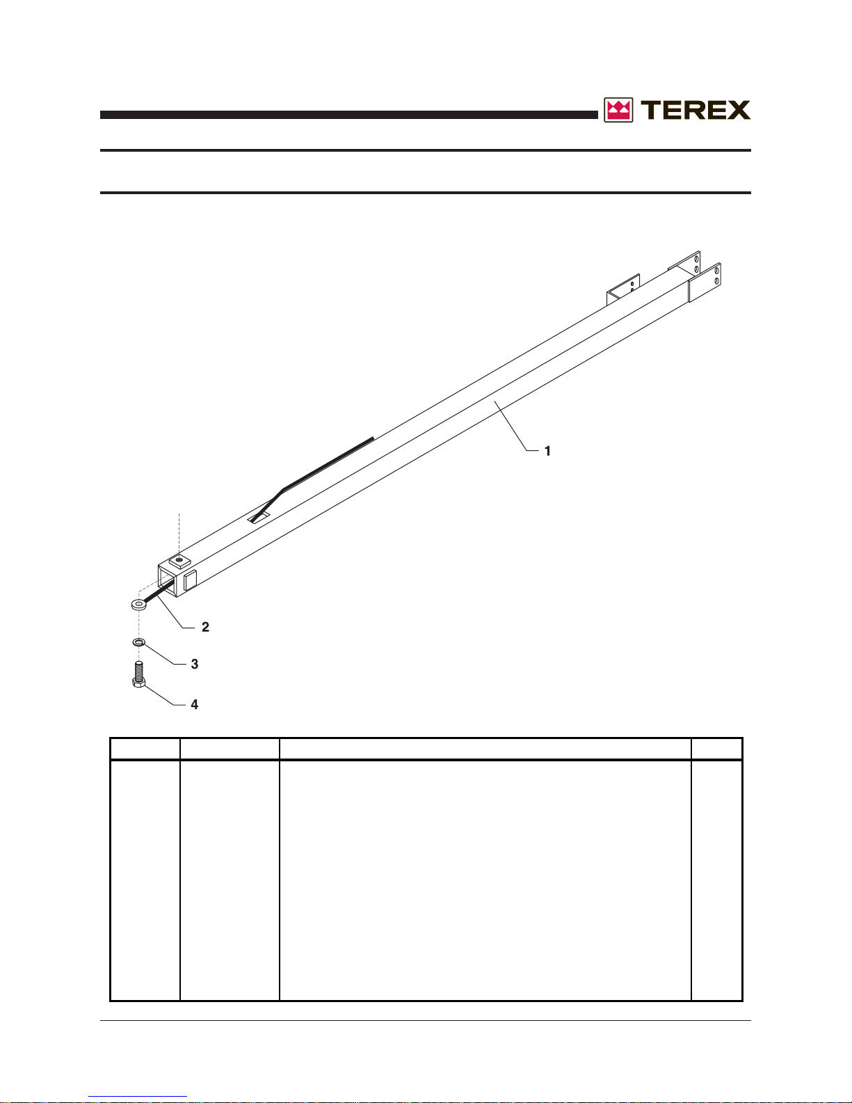
November 2006
2” INCH TOWER SECTION
ITEM # PART # DESCRIPTION QTY.
1 124560 2 SECTION 30'TOWER 1
2 109070 KIT: CABLE ASSEMBLY UPPER 1
3 990470 WASHER LOCK 3/8 1
4 996230 SCREW,3/8-16NCX7/8 HHC,GR 8 ZP 1
Part No. 833002 Rev A AL4000 Light Tower 67
Page 68
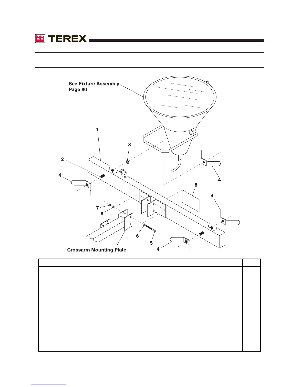
TOWER CROSSARM FIXTURE
November 2006
ITEM # PART # DESCRIPTION QTY.
1 113040 CROSSARM 4-LIGHT 1
2 191781 STUD,3/4X10NCX4-3/4 4
3 990880 WASHER LOCK STAR 3/4 EXT.TOOTH 4
4 123080 FIXTURE MOUNTING WING NUT 4
5 994460 SCREW,3/8-16NCX4-1/2" 2
6 990080 WASHER FLAT 3/8 4
7 990170 NUT LOCK NYLON INSERT 3/8-16NC GR 2 ZPN 2
8 851760 DECAL: DANGER HIGH VOLTAGE.... 1
68 AL4000 Light Tower Part No. 833002 Rev A
Page 69
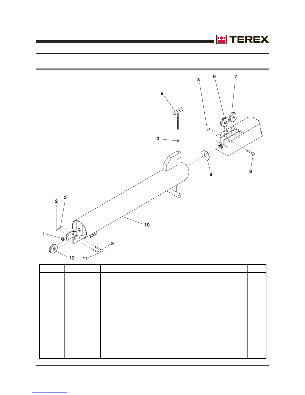
November 2006
6” INCH ROUND TUBE
ITEM # PART# DESCRIPTION QTY.
1 990620 NUT LOCK NYLON INSERT 7/8-14NF HALF JAM 1
2 994920 COTTER PIN 3/32 X 3/4 SS 1
3 990650 COTTER PIN 1/8 X 1 SS 1
4 995190 NUT,LOCK NYLON INSERT 1/2-20NF HALF NUT 1
5 990610 BOLT TEE 1/2-20NF 4-1/2 LG 1
6 188770 SHEAVE 2-13/16 X 1-1/4 CABLE 1
7 188760 SHEAVE 3-1/8 X 1-1/4 CABLE 1
8 992765 CLEVIS PIN STAINLESS STEEL 1/2 X 2 2
9 179850 BUSHING 2.5OD X 13/16 1
10 124530 6" ROUND TUBE 1
11 995790 CLEVIS PIN STAINLESS STEEL 1/4 X 2 1
12 188760 SHEAVE 3-1/8 X 1-1/4 CABLE 1
Part No. 833002 Rev A AL4000 Light Tower 69
Page 70
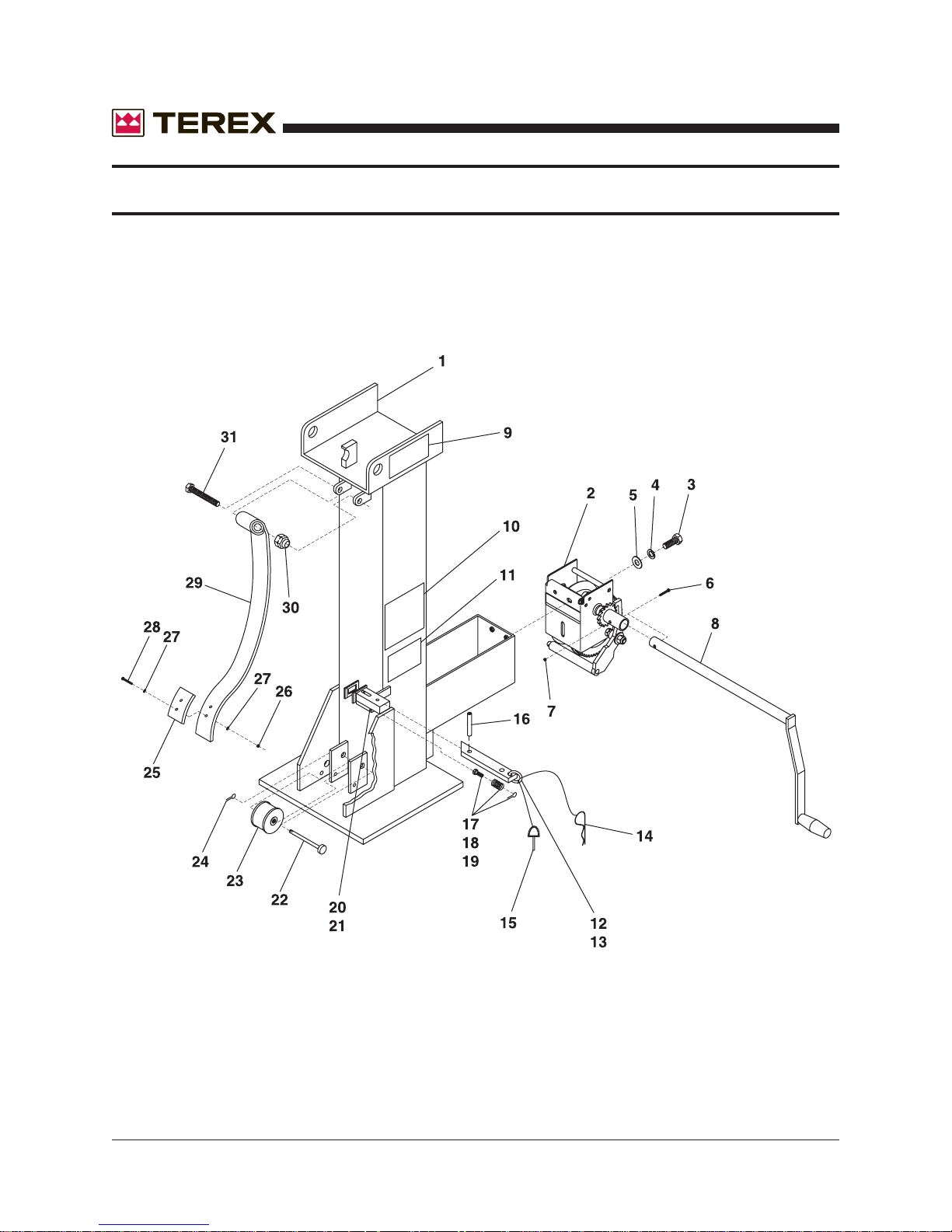
TOWER BASE ASSEMBLY
November 2006
70 AL4000 Light Tower Part No. 833002 Rev A
Page 71
November 2006
ITEM # PART # DESCRIPTION QTY.
1 124490 TOWER BASE 1
2 REFER TO WINCH DRAWING ON NEXT PAGE
3 981450 SCREW,3/8-16NCX1-1/2 2
4 990470 WASHER LOCK 3/8 2
5 990080 WASHER FLAT 3/8 2
6 990140 SCREW 1/4-20NCX2 1
7 990150 NUT LOCK NYLON INSERT 1/4-20NC GR 2 ZP 1
8 124480 WINCH HANDLE W/TUBE 1
9 853670 DECAL: CRUSH AREA 1
10 850090 DECAL: CAUTION STAND CLEAR OF TOWER. 1
11 850105 DECAL: DANGER DO NOT PULL THE VERTICAL 1
12 109517 KIT:LOCK SLIDE PIN includes items 13-21 1
13 113362 PIN,LOCK SLIDE includes items 14-15 1
14 990760 PIN BRIDGE .0915 X 1-7/8 S/S 1
15 120640 PIN W/RING 5/16 X 1-5/8 1
16 990660 ROLL PIN 1/4 X1-5/8 1
17 980340 SCREW,5/16-18NCX1/2 1
18 790710 SPRING COIL 1/2 X2.25 1
19 990650 COTTER PIN 1/8X1 SS 1
20 171636 LOCK PIN SHELL 1
21 171640 LOCK SPRING SHELL 1
22 995760 CLEVIS PIN STAINLESS STEEL 1/2 X3-1/2 1
23 184510 SHEAVE SPOOL 3 X 2-1/2 1
24 990650 COTTER PIN 1/8X1 SS 1
25 186360 BUMPER PAD 1
26 995420 NUT,LOCK NYLON INSERT #10-32 HX M/S JAM 2
27 R980300 WASHER,FLAT,#10 4
28 995050 SCREW,#10-32NFX3/4 LOW HD SHCS ZINC 2
29 193750 SPRING LEAF CUSTOM KICKOUT 1
30 990200 NUT LOCK NYLON INSERT 1/2-13NC GR 2 ZPIN 1
31 981920 SCREW 1/2-13NCX3 HHC GR 8 Y-ZINC 1
Part No. 833002 Rev A AL4000 Light Tower 71
Page 72
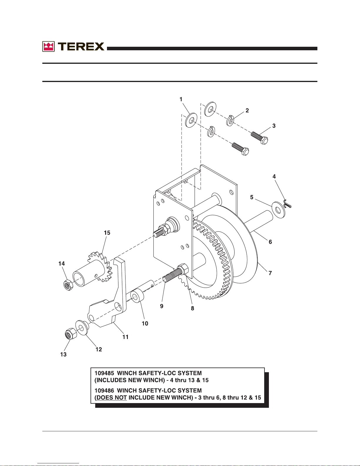
WINCH LOCK ASSEMBLY
November 2006
72 AL4000 Light Tower Part No. 833002 Rev A
Page 73
November 2006
ITEM # PART # DESCRIPTION QTY.
1 990080 WASHER FLAT 3/8 2
2 990470 WASHER LOCK 3/8 2
3 981450 SCREW, 3/8-16NC X 1-1/2 HHCS,GR 5 2
4 990650 COTTER PIN 1/8 X 1 SS 1
5 980480 WASHER, FLAT, C816L, S/S, 1/2 F/W 7/8 OD 1
6 124858 ROLLER WEAR BUSHING 1
7 740050-1 KIT: WINCH & SOCKET 1
8 990200 NUT LOCK NYLON INSERT 1/2-13NC GR 2 ZPIN 1
9 996050 BOLT, 1/2-13NC X 7-1/2 HHC, GRADE 5, ZP 1
10 124857 SPACER .5 ID 1.25 OD 1
11 124855 RATCHET ARM 1
12 124856 BUSHING FLANGE 1.25 OD .5 ID 1
13 990200 NUT LOCK NYLON INSERT 1/2-13NC GR 2 ZPIN 1
14 NPN NUT, 1/2-13, NYLON LOCK, HALF THICK, PART OF 740050-1 1
15 124860 HANDLE SOCKET RATCHETING 1
16 109485 KIT:SAFETY-LOC SYSTEM (with winch) includes items 4-13,15 1
17 109486 KIT:SAFETY-LOC SYSTEM includes items 3-6,8-12,15 1
Part No. 833002 Rev A AL4000 Light Tower 73
Page 74
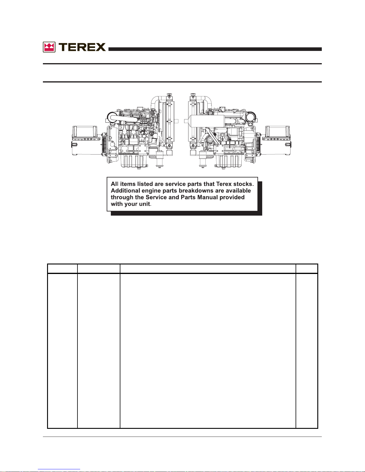
ENGINE/GENSET ASSEMBLY
November 2006
ITEM # PART # DESCRIPTION QTY.
REF 732205PP KUBOTA D1105 ENGINE POWERPACK BUILD EBG2 1
839190 LOW OIL PRESSURE SWITCH 1
741140 HIGH TEMPERATURE SWITCH 1
866125 AIR CLEANER ASSEMBLY 1
866126 AIR CLEANER BODY 1
866127 AIR CLEANER ELEMENT 1
866128 AIR CLEANER COVER 1
866129 AIR CLEANER VALVE 1
866050 OIL FILTER 1
740620 FUEL FILTER, IN-LINE, 5/16 1
839107 FUEL FILTER ASSEMBLY 1
839200 ELEMENT 1
865223 FUEL PUMP 1
866101 STARTER 1
866090 ALTERNATOR 1
866044 2 WIRE STOP SOLENOID 1
839209 V-BELT 1
839261 WATER PUMP 1
839134 FAN, PUSHER 1
839154 OIL DIPSTICK 1
865276 MUFFLER 1
74 AL4000 Light Tower Part No. 833002 Rev A
Page 75
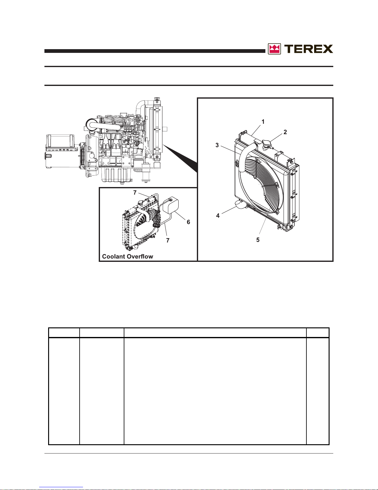
November 2006
RADIA TOR ASSEMBLY
ITEM # PARTS # DESCRIPTION QTY.
1 866114 RADIATOR 1
2 866120 CAP FOR RADIATOR 1
3 839109 HOSE, TOP 1
4 839110 HOSE, BOTTOM 1
5 866113 FAN GUARD 1
6 865307 COOLANT RECOVERY TANK 1
7 890790 HOSE FUEL 1/4X1/2 200# AR
Part No. 833002 Rev A AL4000 Light Tower 75
Page 76
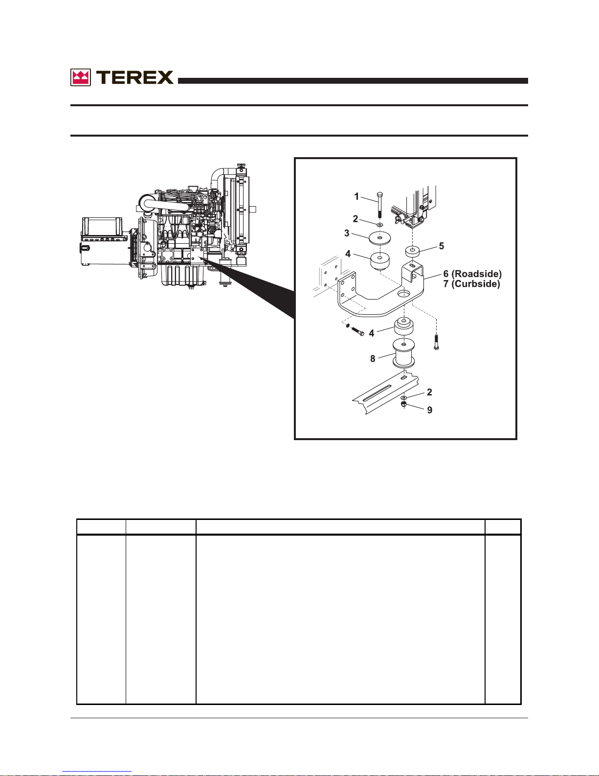
RADIATOR MOUNTING BRACKET
November 2006
ITEM # PART # DESCRIPTION QTY.
1 995380 SCREW, 1/2-13NC X 6-1/2 HHC, GRADE 5, ZP 2
2 990210 WASHER FLAT 1/2 4
3 990415 WASHER, FLAT SNUBBER 2
4 740925 VIBRATION MOUNT, 30 DUR 2
5 740770 VIBRATION MOUNT 35 LB 2
6 124015 ENG.FT/RAD SUPPORT ROADSIDE, D1105/LSA36 (shown) 1
7 124016 ENG.FT/RAD SUPPORT CURBSIDE D1105/LSA36 (not shown) 1
8 124025 ENGINE RISER, 2.75" HIGH FOR 1/2" BOLT 2
9 990200 NUT LOCK NYLON INSERT 1/2-13NC GR 2 ZPIN 2
76 AL4000 Light Tower Part No. 833002 Rev A
Page 77
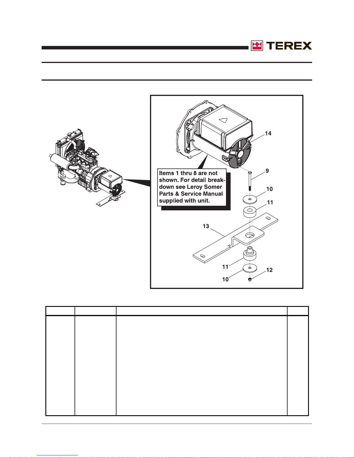
November 2006
GENERATOR MOUNTING BAR
ITEM # PART # DESCRIPTION QTY.
1 836704 NDE BEARING 1
2 836705 DIODE KIT (includes 2 diodes) 1
3 836706 ROTOR BOLT (8 X 245) 1
4 836707 TOP COVER 1
5 836708 END CAP 1
6 836709 FAN 1
7 836710 TERMINAL BLOCK 1
8 836711 CAPACITOR, 22.5mf, (two per unit required) 2
9 996290 SCREW, M10X1.5X90MM HHC, GRADE 8.8, ZP 1
10 990415 WASHER, FLAT SNUBBER 2
11 740925 VIBRATION MOUNT, 30 DUR 3
12 996496 NUT LOCK NYLON INSERT M10 X 1.5 HEX ZP 1
13 189344 GENERATOR MOUNT BAR 1
14 630905 GENERATOR L-S 6KW 120/240 C106 SAE5 LSA36 1
Part No. 833002 Rev A AL4000 Light Tower 77
Page 78
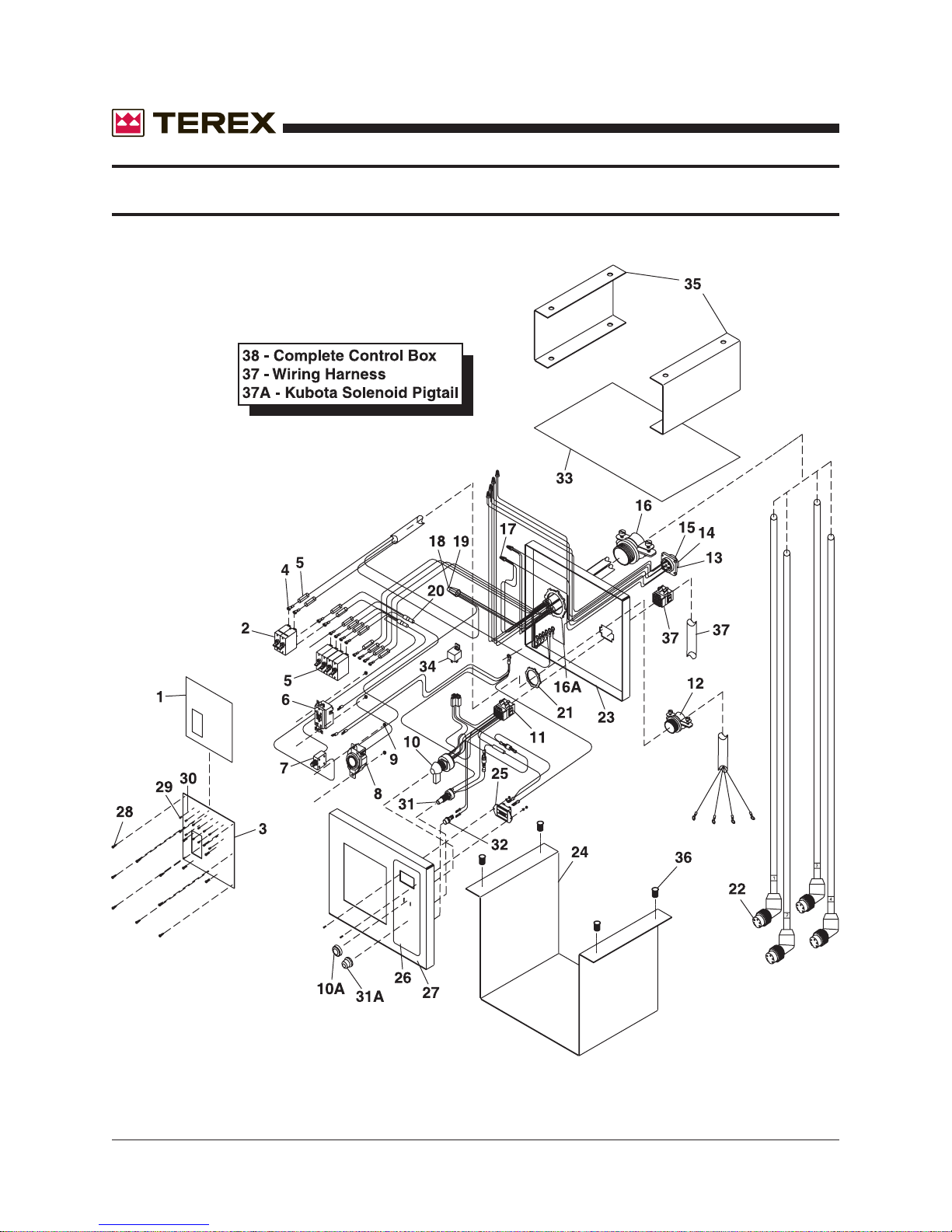
November 2006
ELECTRICAL CONTROL BOX ASSEMBLY
78 AL4000 Light Tower Part No. 833002 Rev A
Page 79
November 2006
ITEM # PART # DESCRIPTION QTY.
1 853294 DECAL: AL/RL CONTROL BOX AC "POWER & LIGHT" 1
2 683680 BREAKER 2P 30A 240V 1
3 186546 CONTROL BOX,FACE PLATE 1
4 709133 TERMINAL,RING 2
5 683870 BREAKER 1P 15A 277VAC 4
6 684640 RECEPTACLE 20A 120V DUPLEX W/GFI 1
7 683970 BREAKER MINI 1P 20A 1
8 684450 RECEPTACLE 30A 240V 1
9 C54100600 NUT, NYLOCK, 8-32 ZINC 5
10 684380 SWITCH, IGNITION LEVER OPERATED 1
10A included with item 10
11 116765 WIRE HARNESS,DC ENGINE 1
12 680030 CONNECTOR,2 SCREW,3/4" 1
13 685672 CONNECTOR 9P,FEMALE 1
14 685674 SOCKETS, FEMALE 9
15 800003 CONNECTOR WITH WIRES (includes 13 and 14) 1
16 686220 CONNECTOR,2 SCREW,1.25 1
16A included with item 16
17 709032 TERMINAL,CLOSED END 2
18 680060 WRAP CAP 1
19 680290 CRIMP SLEEVE 1
20 116770 WIRE HARNESS 1
21 680250 LOCKNUT, CONDUIT 3/4" 1
22 663890 CORD SET FEMALE 6FT 5P 4
23 186542 CONTROL BOX,REAR PANEL 1
24 186540 CONTROL BOX BODY 1
25 260361 HOURMETER, DIGITAL 1
26 853289 DECAL: AL/RL CONTROL BOX DC "ENGINE CONTROLS" 1
27 186544 CONTROL BOX,FRONT PANEL 1
28 996340 SCREW,#10-16X3/4 PH ZP 12
29 995300 SCREW,#6-32X1/4 PAN HD 12
30 994420 WASHER,LOCK,#6 12
31 R660010 SWITCH PUSH-BUTTON 1
31A included with item 31
32 682715 LIGHT INDICATOR 12V RED 1
33 186543 CONTROL BOX,TOP PANEL 1
34 R661490 RELAY 12V DC 30A 1
35 186548 BRACKET, E-BOX HANGER 2
36 993310 NUTSERT,1/4-20UNC 8
37 116820 WIRING HARNESS, FROM ENGINE 1
37A 800004 KUBOTA SOLENOID PIGTAIL 1
38 116805 COMPLETE ELECTRICAL CONTROL BOX, includes 1-36 1
Part No. 833002 Rev A AL4000 Light Tower 79
Page 80
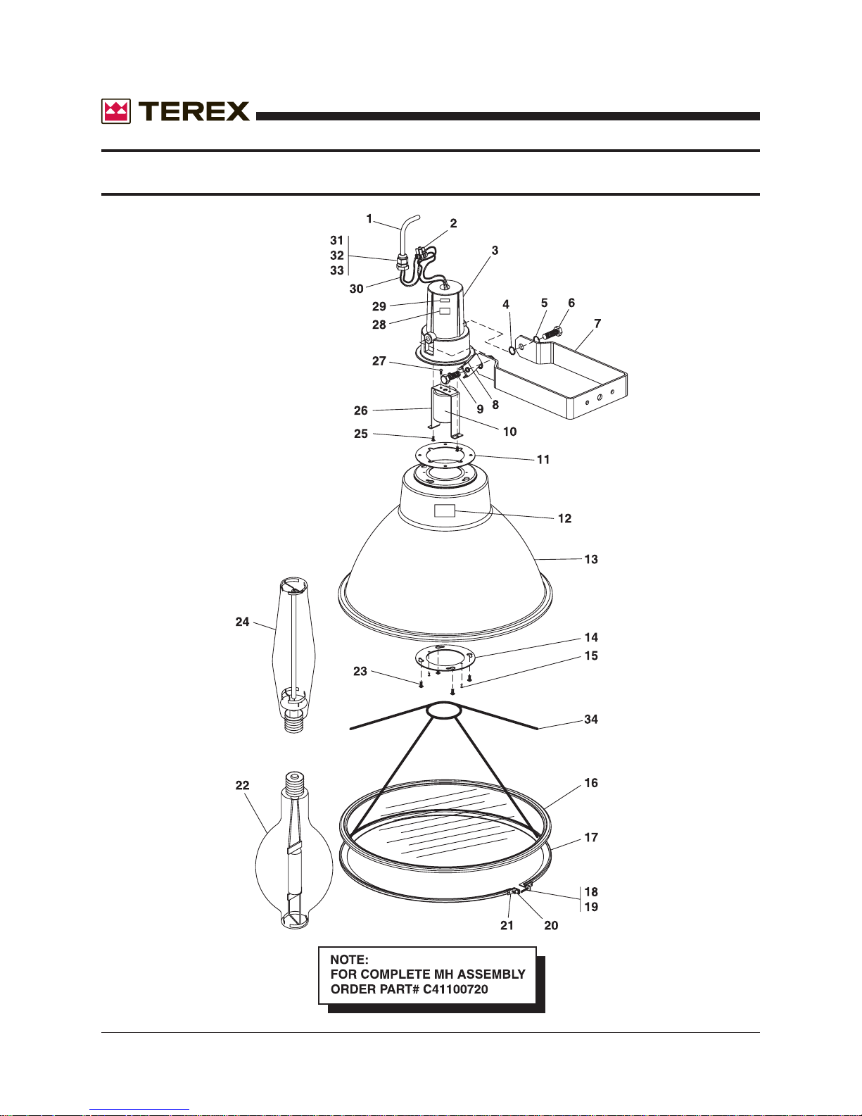
MH/HPS LIGHT FIXTURE ASSEMBLY
November 2006
80 AL4000 Light Tower Part No. 833002 Rev A
Page 81
November 2006
ITEM # PART # DESCRIPTION QTY.
1 663850 CORD SET MALE 5FT. 3P 1
2 709034 TERMINAL STRIP, 2P 2
3 833567 CASTING FOR NEW FIXTURE 1
4 995970 WASHER LOCK STAR 1/2 2
5 991650 WASHER LOCK 1/2 2
6 990810 SCREW 1/2-13NCX1-1/2 HHC GR 2 ZP 2
7 833566 TRUNION 1
8 833573 T-HANDLE 1
9 981640 SCREW 1/2-13NCX1-1/4 HHC GRADE 5 1
10 833569 GASKET FOR REFLECTOR 1
11 833564 SOCKET BASE-MOGUL 1
12 833585 LABEL, FIXTURE CSA APPROVED 1
13 833568 REFLECTOR 1
14 833570 RING,REINFORCING FOR REFLECTOR 1
15 990675 RIVET POP 1/8X.390 GR-1/4-5/16 2
16 833524 LENS W/ GASKET 1
17 833543 CLAMP;LENS TO REFLECTOR 1
18 833574 SCREW,8-32X1" HH SLOT 1
19 833581 WASHER, FIBER FOR BAND 1
20 833578 NUTSERT FOR BAND,8-32 X 1/4 1
21 NPN included with item 17 1
22 160071 LAMP MH 1000W 1
23 833571 SCREW,10-24X5/8 4
24 160140 LAMP HPS 1000W 1
25 833565 SCREW 8-32X3/8 PH 2
26 833563 SOCKET BRACKET 1
27 833577 SCREW,8-32X5/8 2
28 833584 LABEL,105C CORD RATING 1
29 833583 LABEL,WET LOCATION 1
30 833582 FIBERGLASS WIRE SLEEVE 1
31 683950 GASKET 1/2 S/R CONN 1
32 680020 LOCKNUT CONDUIT 1/2 1
33 682470 CONNECTOR STRAINRELIEF 1
34 120102 LAMP SUPPORT 2
35 C41100720 COMPLETE FIXTURE ASSEMBLY 1
(Includes items 1-34)
Part No. 833002 Rev A AL4000 Light Tower 81
Page 82
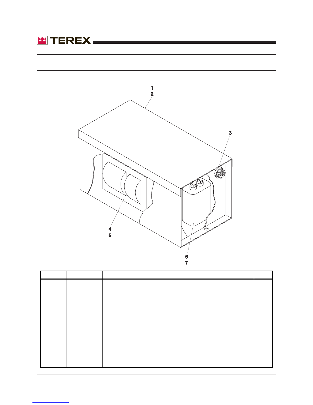
BALLAST ASSEMBLY
November 2006
ITEM # PART # DESCRIPTION QTY.
1 114355 BALLAST BOX MH 1
2 114895 BALLAST BOX HPS 1
3 663860 CONNECTOR,5P,MALE 1
4 160030 MH TRANSFORMER AND CAPACITOR 1
5 160040 HPS TRANSFORMER AND CAPACITOR 1
6 160032 CAPACITOR ONLY 24uF MH 60Hz 1
7 160042 CAPACITOR ONLY 24uF HPS 60Hz 1
82 AL4000 Light Tower Part No. 833002 Rev A
Page 83
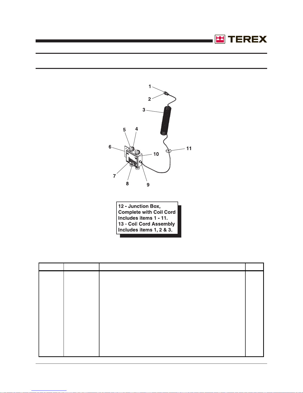
November 2006
COIL CORD & JUNCTION BOX
ITEM # PART # DESCRIPTION QTY.
1 685673 PIN, MALE 9
2 685671 CONNECTOR 9P,MALE 1
3 660287 CORD RETRACT 14/7 1
4 663870 CONNECTOR 3P FEMALE 4
5 663880 DUST CAP W/CHAIN 4
6 C48300108 JUNCTION BOX 1
7 680190 BOX COVER 2GANG W/GASKET 1
8 852800 DECAL: CAUTION TIGHTEN FIXTURE CONNECTOR 1
9 680080 GRIP-HUBBLE 1
10 720440 WEATHERSTRIP ADHESIVE AR
11 CR58C012 COIL CORD BULKHEAD 1
12 112555 JUNCTION BOX, COMPLETE WITH COIL CORD includes 1-11 1
13 112575 COIL CORD ASSEMBLY 1
(Includes items 1, 2 and 3)
Part No. 833002 Rev A AL4000 Light Tower 83
Page 84
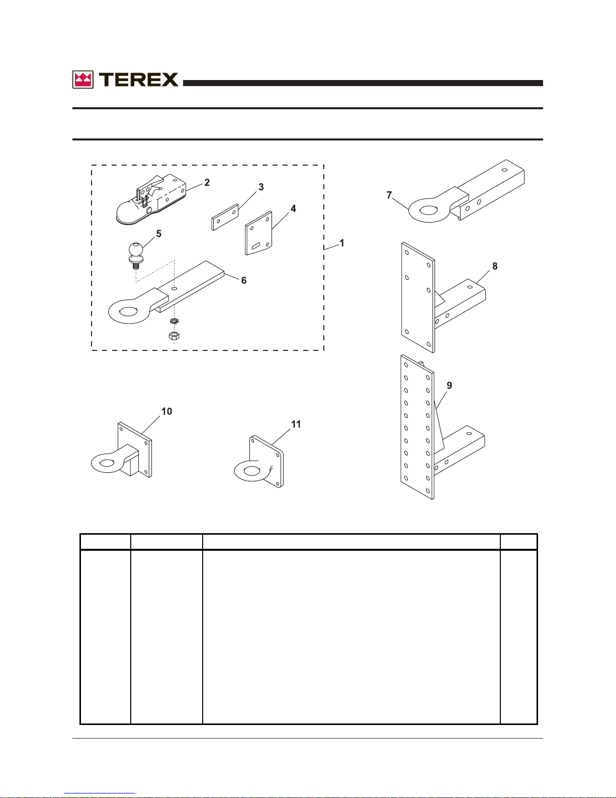
TRAILER HITCHES
November 2006
ITEM # PART # DESCRIPTION QTY.
1 940000 KIT: COMBO HITCH, includes items 2-6 1
2 840120 COUPLER, 2", BOLT ON 1
3 176336 COMBO HITCH SIDE SPACER 2
4 176335 COMBO HITCH SIDE PLATE 2
5 840470 BALL, 2" 1
6 121572 COMBO HITCH RING, 16" LONG 1
7 213770 RING HITCH BOLT-ON, 2-1/2 ID 1
8 124450 ADJUSTABLE HEIGHT HITCH, 24" 1
9 221580 ADJUSTABLE HEIGHT HITCH, 18" TO 36" 1
10 211410 RING HITCH FOR ADJ. HEIGHT HITCH, 2 1/2" ID 1
11 841200 RING HITCH FOR ADJ. HEIGHT HITCH, 3" ID 1
84 AL4000 Light Tower Part No. 833002 Rev A
Page 85
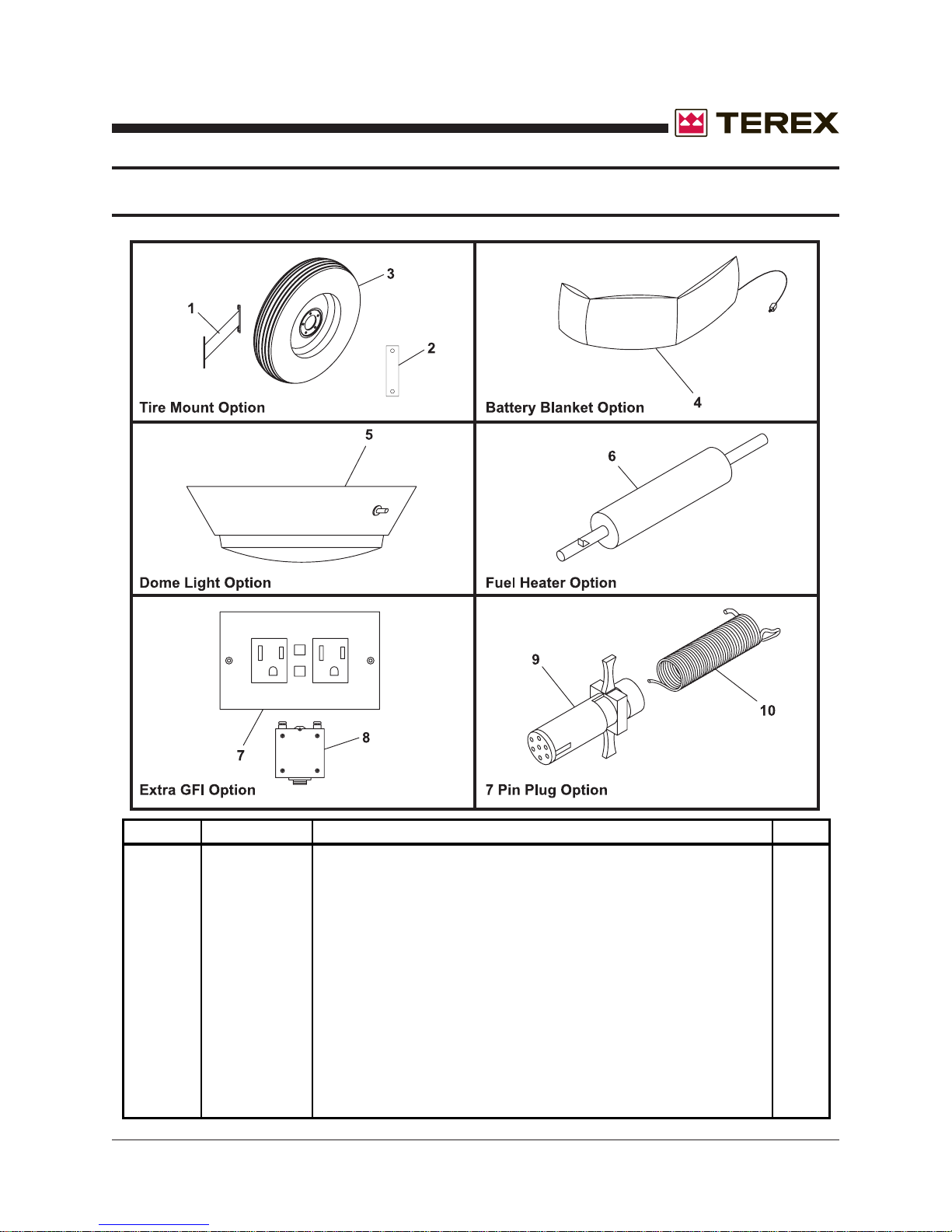
November 2006
AL4000 OPTIONS
ITEM # PARTS # DESCRIPTION QTY.
1 124310 SPARE TIRE MOUNT 5-LUG WHEEL 1
2 188070 CLAMP,SPARE TIRE BRKT,TONGUE MNT. 2
3 841060 TIRE & WHEEL MOUNTED P205/75-15 LOAD-B 1
4 160530 BATTERY BLANKET THERMO 284-4001 36"LG 1
5 684030 LIGHT DOME WITH SWITCH 1
6 741690 FUEL LINE HEATER, DIESEL,12V,150W 1
7 684640 RECEPTACLE 20A 120V DUPLEX W/GFI 1
8 683970 BREAKER MINI 1P 20A 1
9 663400 CONNECTOR TAIL LIGHT 7 POLE 1
10 663405 CONNECTOR,TAIL LIGHT,7 POLE CABLE GUARD 1
Part No. 833002 Rev A AL4000 Light Tower 85
Page 86

AL4000 OPTIONS (CONTINUED)
November 2006
ITEM # PARTS # DESCRIPTION QTY.
11 174170 BATTERY HOLDOWN ANGLE 14.50 1
12 161085 BATTERY, WET, 12V GR24, 700 AMP HEAVY-DUTY L/A 1
13 182331 BATTERY HOLD-DOWN ROD,1/4X11-1/4 2
14 110040 OUTRIGGER 2X2X30 2
15 124412 TRAILER FRAME,41X70, FOR EXTRA OUTRIGGERS 1
16 109150 KIT: OUTRIGGER PLUNGER PIN ASSY 2
17 840222 JACK SNAP RING 2
18 841430 JACK SIDEWIND LONG 3000 LB 2
19 663525 LIGHT,SIDE MARKER, AMBER 2
20 663520 LIGHT LICENSE TAG W/BRKT 1
21 663840 LIGHT TRAILER RECESSED, STOP, TURN, TAIL 2
22 160992 WINCH W/O CABLE 1
23 663780 SWITCH TOGGLE 1P 2T MOMENTARY 20ADC 1
24 160993 WINCH SOLENOID PACKAGE 1
25 113583 WINCH SWITCH WITH SOLENOID (includes items 23 and 24) 1
86 AL4000 Light Tower Part No. 833002 Rev A
 Loading...