

Page 1
User Manual
C
C
C
o
o
o
p
p
p
y
y
y
r
r
r
i
i
i
g
g
g
h
h
h
t
t
t
©
©
©
2
2
2
0
0
0
1
1
1
5
5
5
T
T
T
e
e
e
r
r
r
a
a
a
s
s
s
i
i
i
c
c
c
T
T
T
e
e
e
c
c
c
h
h
h
n
n
n
o
o
o
l
l
l
o
o
o
g
g
g
i
i
i
e
e
e
s
s
s
I
I
I
n
n
n
c
c
c
.
.
.
A
A
A
l
l
l
l
l
l
R
R
R
i
i
i
g
g
g
h
h
h
t
t
t
s
s
s
R
R
R
e
e
e
s
s
s
e
e
e
r
r
r
v
v
v
e
e
e
d
d
d
.
.
.
Page 2
1
Spider
User Manual
Chapter 1 :
1-1
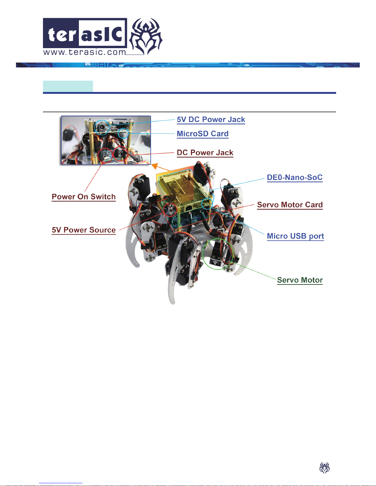
The Terasic Spider is a six-legged walking robot which is driven with 18 Servo Motors.
These 18 Servo Motors are controlled by PWM signals generated from the Altera DE0Nano-SoC board embedded inside the Terasic Spider. The Terasic Spider itself can
be remotely controlled by a bluetooth enabled Android device. The software app we
developed can control the Terasic Spider, allowing it to move in four directions, swing
based on the g-sensor data, and even complete a dance with pre-dened movements.
All the source codes of the Terasic Spider is available with the kit. You can modify the code
to improve or to change the Terasic Spider's functions according to specic applications.
The source codes include Andriod project, Linux application project, and a Quartus project.
Note that there is a 2x20 GPIO expansion header available on the DE0-Nano-SoC board.
You are free to use it to expand functions, such as camera, ultrasonic, or anything else.
Introduction
Terasic Spider
Page 3
2
Spider User Manual
Spider User Manual
Spider User Manual
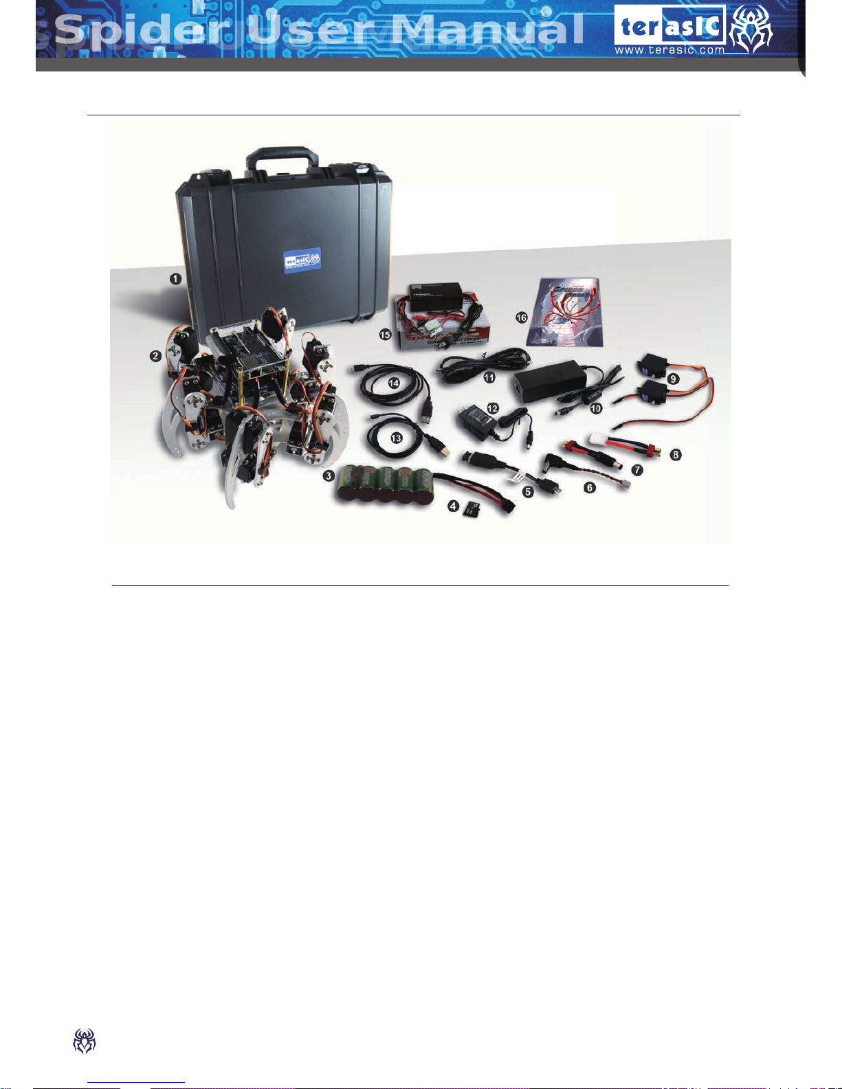
The kit contains:
1. Spider Box
2. Assembled Spider
3. Battery
4. MicroSD Card (Pre-programmed & Installed)
5. USB Bluetooth Dongle with Adapter
6. 5V to DC Plug Cable
7. Battery to DC Jack Cable
8. Battery Connector Adapter Cable
9. Servo Motor x2 (spares)
10. 12V DC Power Adapter
11. USA 3-pin AC Cord for 12V Adapter
12. 5V DC Power Adapter
13. Mini USB Cable
14. Micro USB Cable
15. Battery Charger
16. User Manual
1-2
Package Contents
Page 4
3
Spider User Manual
Spider User Manual
1-3
2-1
2-2
Getting Help
Power System of Spider
Power up the Spider with DC Power Adaptor
These are the different contact methods available to contact us in case you encounter any
problems:
• Terasic Technologies
9F, No. 176, Sec. 2, Gongdao 5th Rd, East Dist, Hsinchu City, 30070, Taiwan
Tel: +886-3-575-0880
Email: support@terasic.com
http://spider.terasic.com
Chapter 2 :
Start Up - Instruction
• Main Motor Board is powered by battery pack (two packs at once) or 12V DC adaptor.
• DE0-Nano-SOC board is powered from the DC jack on the motor board.
• When Battery is used as power source, Battery pack must be bundled with the
conversion cable to the DC power connector.
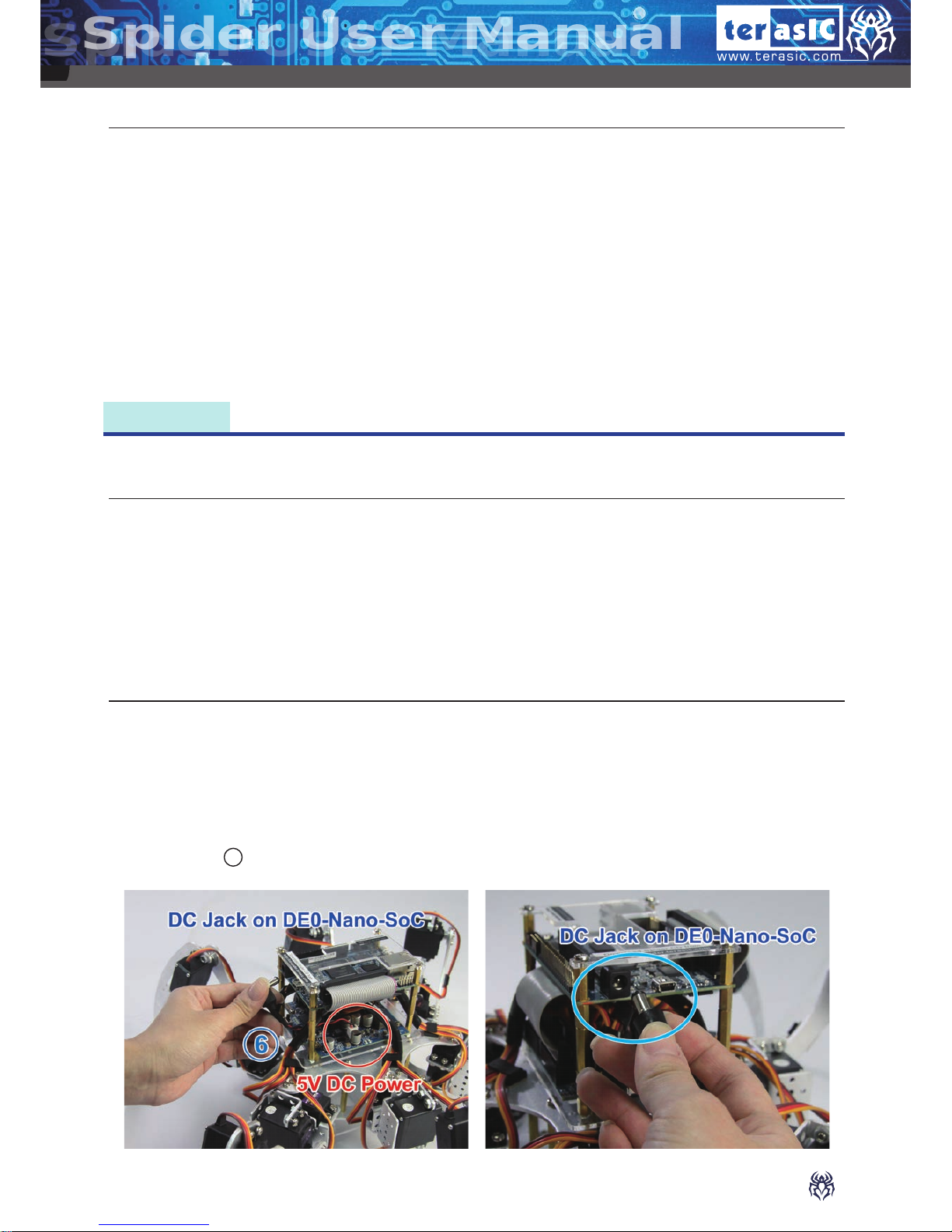
1. Please make sure the Spider is placed on the at ground and the surrounding area (at
least 20 cm radius) is cleared.
Note: Avoid the Spider's legs getting obstructed, or the motor may be damaged.
2. Connect 5V DC power from the Servo Motor Card to the DC Jack on the DE0-NanoSoC via “ 6 5V to DC Jack Cable”.
Page 5
4
Spider User Manual
Spider User Manual
Spider User Manual
6. The Spider will begin to stand up after LED7
blinks for 10 seconds. LED0~6 will stay on
once the initialization is completed.
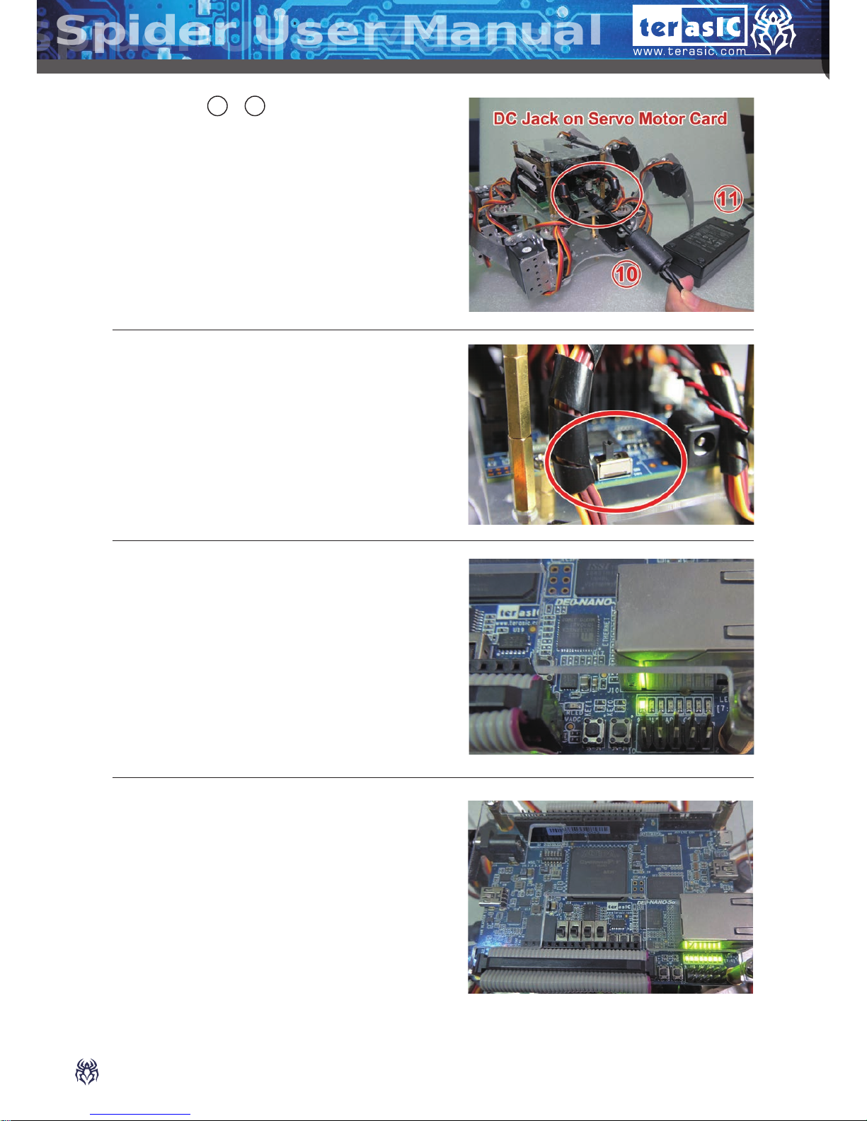
3. Connect “ 10 & 11 12V DC power” to the DC
jack on the Servo Motor Card.
4. Switch the Power Switch on the Servo Motor
Card to "ON" position.
5. After 5 seconds, the LED7 on DE0-NanoSoC will blink.
Page 6

5
Spider User Manual
Spider User Manual
7. Press KEY1 on the DE0-Nano-SoC and the
Spider will start the “Dancing” demonstration.
1. Switch the Power Switch on the Servo Motor
Card to "OFF" position.
2. Remove the 12V DC Power
3. Connect the Batter-to-DC jack cable to the
battery.
4. Install the battery into the Spider Robot from
behind.
2-3
Power up the Spider with Battery
Page 7

6
Spider User Manual
Spider User Manual
Spider User Manual
7. Switch the Power Switch on the Servo Motor
Card to "ON" position.
8. After 5 seconds, the LED7 on DE0-NanoSoC will blink.
5. Check if the battery is installed properly from
the other side. The battery needs to be center
placed.
6. Connect the battery to the DC Jack on the
Servo Motor Card via “ 7 Battery to DC Jack
Cable".
Page 8

7
Spider User Manual
Spider User Manual
10.Press "KEY1" on the DE0-Nano-SoC and the
Spider will start the “Dancing” demonstration.
1. When the Spider Robot is idle for a while i.e. not receiving any command, it will enter
power saving mode automatically. It will remain its current position with all the servo
motors turned off.
2. The LED0 on the DE0-Nano-SoC will remain on and the LED7 will be flashing while
other LEDs onboard will be turned off.
3. The Spider Robot will "wake-up" upon receiving any command either from the pushbutton onboard or transmitted from your Android device. The status of LED0 and LED7
will remain the same while other LEDs will be turned on.
4. The Spider Robot will return to its last position upon wake-up before executing the new
command.
9. The Spider will begin to stand up after LED7
blinks for 10 seconds. LED0~6 will stay on
once the initialization is completed.
2-4
Auto Power Saving Mode
Page 9

8
Spider User Manual
Spider User Manual
Spider User Manual
4. Scan the QR code to your cell phone.
2. After downloading, open the QR code scanner from the
cell phone.
3. You can find the required QR code at the
bottom of the Spider.
Chapter 3 :
Control the Spider with Smart Phone (Android)
Besides using Key1 to make the spider dance, you can also use cell phone
application as one of the control methods.
1. Download and install any QR Code application you
preferred from your google app store.
Page 10

9
Spider User Manual
Spider User Manual
8. After the Spider stretches its legs, then launch
Android Bluetooth utility to search "socfpga-0" and
pair it with pin code 0000 (if required).
5. Download and install the "TerasicSpider" application into the cell
phone.
6. Insert the “ 5 USB Bluetooth Dongle with the
adapter ” into the Micro USB port on DE0-NanoSoC.
7. Switch the Power Switch on the Servo Motor
Card to "ON" position.
Page 11

10
Spider User Manual
Spider User Manual
Spider User Manual
12. If the connection is established successfully, the color of
Bluetooth logo will turn to green. The Spider can now be
controlled from the cell phone.
10. Click on the Search Button on the top-right
corner.
11. The screen will have a pop up window showing “select a device
to connect”, select “socfpga-0”.
9. Launch the TerasicSpider application on the cell phone.
Page 12

11
Spider User Manual
Spider User Manual
13. The four Arrow Buttons control the Spider movement in four
directions (default mode). Spider’s movement speed can be
controlled by the Speed Slider. Slide left to slow down the
Spider; Slide right to speed up.
14. Press the "K-Mode" button will switch to "G-sensor" mode.
Switch again will return to the default mode controlled by The
four Arrow Buttons.
15.Press the "DEMO" button to execute the "Spider Dancing Demo".
Page 13

12
Spider User Manual
Spider User Manual
Spider User Manual
3. Start charging by connecting power to the charger.
4. The red LED will stay ON when it's charging.
5. The green LED will stay ON when the battery is fully charged.
Chapter 4 :
Charge the Battery
After the battery run out of charge, you can do the following steps to recharge your
battery.
1. Switch the current of “ 15 Battery Charger” to 2.0A.
2. Connect the battery to the charger with the
“ 8 Adapter Cable”.
Page 14

13
Spider User Manual
Spider User Manual
There is a CPLD on the Servo Motor Card
to manage the power supplied to the Servo
Motors. It provides battery level indication and is
responsible for powering off the spider when the
battery low or power consumption is too large.
There are three orange LEDs and one red LED
on the Servo Motor Card for the indication of
power status. The three orange LEDs indicate the
power level of the battery. The red LED indicates
the status of power exception.
When the battery is full, the three orange LEDs are lighted. When there's only one orange
LED lighted, it indicates the battery power is low and users should recharge the battery.
When 12V DC is supplied, the three orange LEDs will always light.
The motor card will turn off the system power automatically when the battery level is
approaching the threshold of over discharge. The three orange LEDs will be turned off and
the red LED will light up as a reminder. The Servo Motor Card will turn off the power for
both Servo Motors and DE0-Nano-SoC immediately. Please turn off the power switch of
Servo Motor Card manually to stop the CPLD on the Servo Motor Card from consuming
the battery power, as it could over discharge the battery. The battery will not be able to be
charged afterwards.
When the power consumption is too large (usually caused by the Servo Motor gets stuck
by the obstacle), the Servo Motor Card will also turn off the power for the Servo Motors
and DE0-Nano-SoC. The red LED is lighted and the power of Servo Motor Card needs to
be reset after removing the obstacle.
All the source codes of the Terasic
Spider is available on the Spider
System CD. You can modify the
code to improve or to change the
Terasic Spider's functions according
to their specific applications. The
source codes include andriod
project, linux application project,
and a Quartus project. The System
CD is available on
http://cd-spider.terasic.com
Chapter 5 :
Appendix
Page 15
14
Spider User Manual
Spider User Manual
Spider User Manual
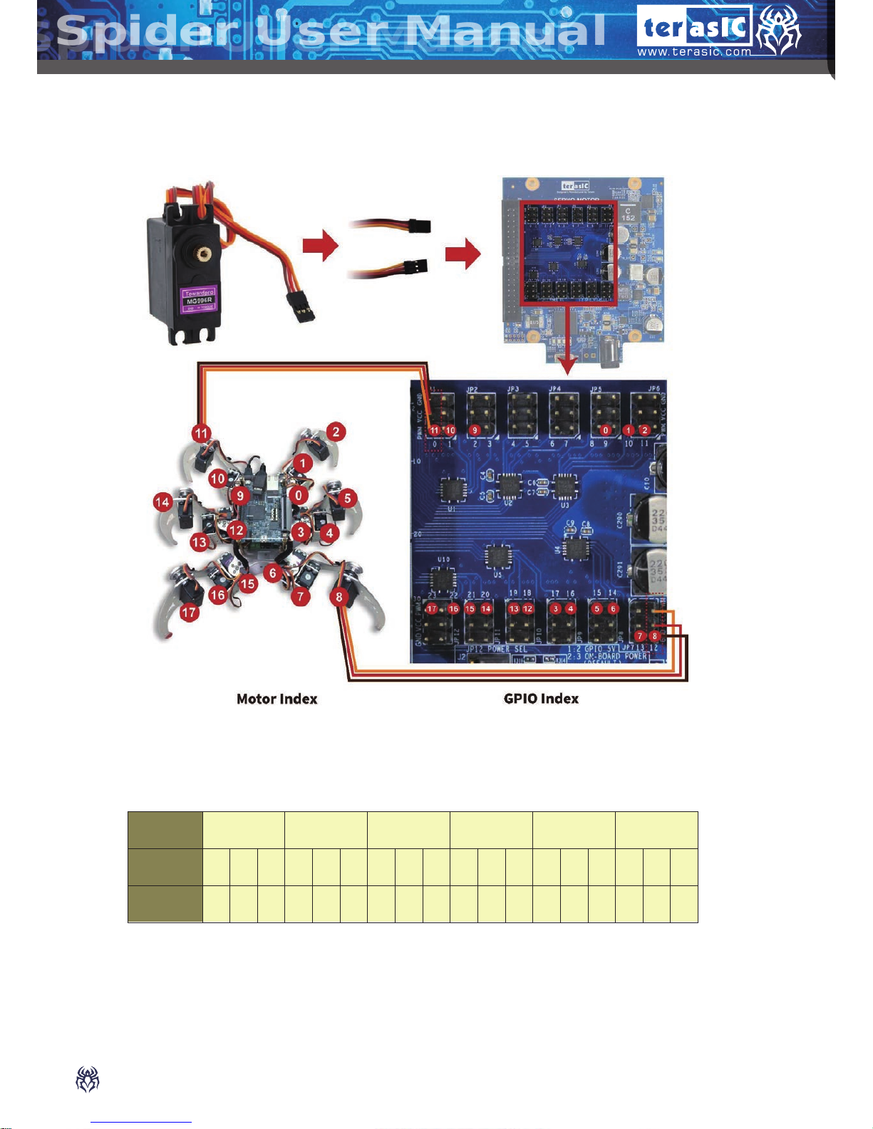
Servo Motor Connections
Mapping Table
Leg
Right-
front
Right-
middle
Right-
back
Leftfront
Left-
middle
Left-
back
Motor
Index
0 1 2 3 4 5 6 7 8 9 10 11 12 13 14 15 16 17
GPIO
Index
9 10 11 17 16 15 14 13 12 2 1 0 18 19 20 21 22 23
Page 16

For more details, please contact us at:
Tel:+886-3-5750880 Fax:+886-3-5726690 sales@terasic.com
www.terasic.com Copyright © 2015 Terasic Inc. All Rights Reserved.
 Loading...