

Page 1
TERAL INC.
Instruction Manual
Volute Pump
Model: LS2 / LS
LS2-e / LS-e
Warning
Do not carry out operation, inspection or maintenance of the pump until you read this manual and
understand the content.
Keep this manual carefully at hand so that it can be consulted at anytime when operating, inspecting or
maintaining the pump.
For contractors who carry out equipment work:
Please be sure to deliver this manual to the customer who will operate, inspect or maintain the pump.
Page 2

Limited warranties
1. In the event of a failure or breakage under proper use of the product during the warranty period,
equipment supplied by Teral Inc. shall be repaired or replaced free of charge within the scope of the
relevant part, provided that such failure or breakage is attributable to inadequacy of the design or
workmanship of the equipment.
The warranty period of this product shall be one year after the date of delivery.
2. The warranty mentioned in the above clause shall be only the mechanical warranty of the defective part,
and shall not cover any expenses or other damage arising from the failure or breakage. Moreover, the
warranty is available for Japan domestic use only.
3. In the event of the following failures and breakage, the costs of the repairs shall be borne by the user.
(1) Failures and breakage attributable to equipment that was not delivered by Teral Inc.
(2) Failures and breakage after the expiration of the warranty period
(3) Failures and breakage caused by disasters or force majeure, such as fire, acts of God, or
earthquakes
(4) Failures and breakage resulting from repairs or modifications made without the con se nt of Teral
Inc.
(5) Failures and breakage when parts other than those designated by Teral Inc. are used
(6) Failures and breakage caused by use or storage outside the specification range
4. Teral Inc. shall not be liable for the damage caused by incorrect or reckless use of the pump. Cost and
expenses incurred for sending engineer(s) in such a case shall be borne by the use r.
5. If the cause of the failure is unclear, necessary actions sh all be determined through mutual
consultation.
I
Page 3

II
Purpose of this manual
The purpose of this manual is to provide the user with detailed information necessary to properly operate,
maintain and inspect the pump. Incorrect operation of this product may lead to an unexpected acci dent.
Please use the product correctly according to this instruction manual.
This manual contains the following information and is intended for persons experienced in the operation of
pumps, or for those who have been trained by such experienced operators. Only qualified personnel such
as licensed electrical engineers are allowed to carry out the electrical wiring work.
Contents
(Page)
Limited warranties ....................................................................................................................................I
Purpose of this manual........................................................................................................................... II
Contents.................................................................................................................................................... II
1. Safety precautions............................................................................................................................... 1-1
1.1 Types and meanings of safety signs and graphic symbols.........................................................1-1
1.2 Safety precautions....................................................................................................................... 1-1
1.3 Location of warning labels and caution labels.............................................................................1-4
2. Configuration and overview of the pump.............................................................................................2-1
2.1 Model type description ...............................................................................................................2-1
2.2 Part names and functions............................................................................................................2-1
2.3 Standard specifications...............................................................................................................2-2
3. Installation ........................................................................................................................................... 3-1
3.1 Before using the pump ................................................................................................................3-1
3.2 Precautions for installation..........................................................................................................3-1
3.3 Installation procedure..................................................................................................................3-3
3.4 Coupling alignment procedure ....................................................................................................3-4
3.4.1 Alignment (CF-A type coupling)........................................................................................... 3-5
3.4.2 Alignment (AB type coupling) .............................................................................................. 3-7
3.5 Precautions for piping work.........................................................................................................3-8
3.6 Precautions for wiring work....................................................................................................... 3-11
4. Operation............................................................................................................................................. 4-1
4.1 Check items before test operation...............................................................................................4-1
4.1.1 Check items related to the electrical system.......................................................................4-1
4.1.2 Check items related to the pump.........................................................................................4-1
4.2 Running the pump (test operation).............................................................................................. 4-2
5. Maintenance and inspection................................................................................................................5-1
5.1 Precautions for maintenance and inspection..............................................................................5-1
5.2 Shaft seal parts............................................................................................................................5-2
5.2.1 Gland packing...................................................................................................................... 5-2
5.2.2 Mechanical seal...................................................................................................................5-3
5.3 Bearings ...................................................................................................................................... 5-3
5.4 Maintenance checklist.................................................................................................................5-4
6. Troubleshooting................................................................................................................................... 6-1
Page 4
1. Safety precautions
Before using the unit, thoroughly read this “Safety precautions” to properly use the product.
Information described below is vital to safe and proper use of the unit and prevention of hazard
and/or damage.
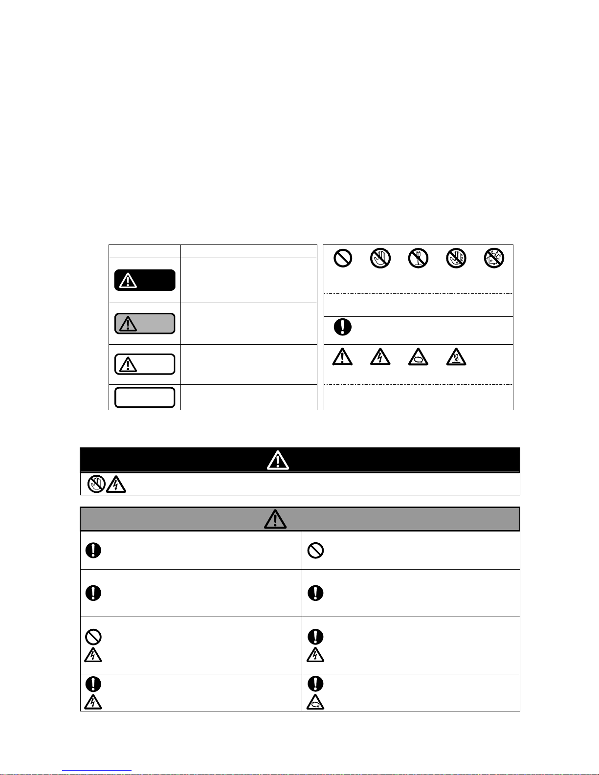
1.1 Types and meanings of safety signs and graphic symbols
This instruction manual divides precautions into the following four categories according to the level
of hazards (or the severity of the accident). In addition, prohibited or mandatory actions as well as
cautions are indicated with a graphic symbol.
Be sure to understand the meanings of the following terms and comply with the content
(instructions) of the instruction manual.
Explanation of warnings Explanation of the graphic symbols
Safety sign Meaning
Don’ts Do not touch Do not
disassemble
Do not touch
with wet
hand
Do not
expose to
water
Danger
Indicates an imminently hazardous
situation. Failure to observe this will
result in death or serious injury.
These graphic symbols indicate prohibited actions (that
must NOT be done).
Warning
Indicates a potentially hazardous
situation. Failure to observe this will
result in death or serious injury.
Do’s
This graphic symbol indicates mandatory
actions (that must be done).
Caution
Indicates a potentially hazardous
situation. Failure to observe this will
result in minor or moderate injury or
property damage.
Caution Electric
shock hazard
Rotation
hazard
Hot surface
Note
Indicates information that is in
particular to be noted or emphasized.
These graphic symbols indicate existing hazards to
beware of.
1.2 Safety precautions
Danger
Once the main power is turned on, do not touch any live parts.
A high voltage applied to live parts may cause a serious electric shock, thus leading to death.
Warning
Properly move the unit according to lifting
instructions.
Otherwise, the unit may fall, thus leading to an injury or
damage.
Do not carry out any work with/on the pump that is
being lifted.
Otherwise, the unit may fall, thus leading to an injury or
damage.
Only those who are authorized by the site manager
are allowed to operate the pump.
Operation by unskilled personnel may lead to an unforeseen
accident.
Installation, maintenance, and inspection must
only be carried out by personnel who have been
trained to handle the pump.
Operation by unskilled personnel may lead to an unforeseen
accident.
Only qualified personnel, such as licensed electrical
engineers, are allowed to carry out electric work.
Otherwise, it may lead to an electric shock, fire, failure, or
other problems.
Use high-quality wiring equipment and devices,
and carry out wiring work safely and securely
according to the technical standards for electrical
facilities, as well as the indoor wiring regulations.
Otherwise, it may lead to an electric shock, fire, or other
problems.
Securely install the ground wire and ensure to carry
out grounding work.
Otherwise, it may lead to an electric leak or electric shock.
Be sure to install the leakage circuit breaker at the
main power supply.
Otherwise, it may lead to an electric shock or fire.
1-1
Page 5
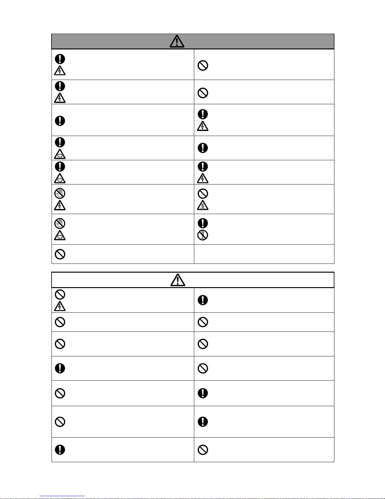
Warning
Correctly and securely connect the wires according
to the wiring diagram within the terminal box and the
instruction manual.
Incorrect wiring may cause a fire, electric shock, failure, or
other problems.
Do not connect the ground wire to a gas pipe or
water pipe.
Such a connection is illegal and leads to an electri c shoc k,
explosion, or fire.
Check the wiring sections and wires for any
looseness.
A loose connection may cause a fire or electric shock.
Do not run the unit if abnormal condition is
observed in any operation, movement, parts, etc.
Otherwise, it may lead to an injury, failure, or various
accidents.
Before starting the unit or carrying out
maintenance/inspection work, ensure that all the
relevant workers are informed of the operation and
that there are no workers in the dangerous zone.
Otherwise, it may lead to an unforeseen accident.
Before starting the maintenance or inspection
work, be sure to stop the pump and turn off the
main power of the panel board.
Otherwise, it may lead to an electric shock, injury, damage,
or leakage.
Before rotating the main shaft by hand to check its
smooth rotation, be sure to turn off the main power.
Otherwise, it may lead to an injury.
In the event of a power failure, be sure to turn off
the power switch.
Otherwise, the pump may suddenly start up on restoration of
the power, thus leading to an injury.
Be sure to put a shaft coupling protective cover
during operation.
Otherwise, it may lead to an injury or damage.
Be sure to keep the terminal box cover attached
during the operation of the pump.
Otherwise, it may lead to an electric shock.
After turning on the power, do not touch any parts of
the pump other than those required for operation.
Otherwise, it may lead to an electric shock or injury.
Do not perform zero-discharge operation for more
than one minute continuously.
Otherwise, the temperature and pressure may increase
inside the pump, thus damaging the pump or causing steam
to blow off.
Do not put your fingers or foreign objects into any
openings or rotating part of the motor during
operation.
Otherwise, it may lead to an injury or damage.
For overhaul, replacement of parts, or repairs,
contact Teral or the service center specified by
Teral.
If unskilled personnel carry out work that requires special
knowledge, it may lead to an accident or failure.
Do not use the product in any explosive
atmosphere.
Otherwise, it may lead to any injury or fire.
Caution
Do not use the unit outside the range of the product
specifications.
Otherwise, it may lead to an electric shock, fire, leakage,
failure, or other problems.
Check that the delivered items are exactly what
you ordered.
The use of a wrong product may cause an injury or failure.
Do not modify the pump.
Any accident or damage due to the modific ation by customer i s
beyond our warranty.
Do not run the pump at a frequency exceeding 60
Hz (50 Hz for models dedicated to 50Hz).
Otherwise, it may lead to motor burnout or a fire.
Do not use a single pump unit as the only means of
directly operating key facilities or sustaining life.
In the event of a failure, the water supply may stop. Ensure to
make a backup unit available for operation.
Do not give the product any physical shock during
transportation, transfer, and installation.
Otherwise, it may cause damage to the product.
Ensure that the floor at the unit’s installation place is
waterproofed and fitted with drainage.
Otherwise, it may lead to serious damage in the event of
leakage.
Do not use the unit at an incorrect power voltage.
An incorrect voltage may damage the motor.
When two or more pumps are installed together,
every pump should have its own separate suction
piping.
Otherwise, it may lead to an abnormal operation.
Strictly observe the precautions for installation on
pump installation environment.
Otherwise, It may lead to quick damage of the pump.
Do not step on the pump, motor, wiring and piping.
Otherwise, it may lead to an injury, damage, or other problems.
Before unpacking the delivered container, check
that the container is placed in the correct
orientation (not upside down). Carefully unpack the
container, while paying special attention to nails.
Otherwise, it may lead to an injury or damage.
Operate the controls carefully.
Otherwise, it may lead to an injury or damage.
Do not install two or more different cables or
control wires in one pipe or duct.
Otherwise, it may lead to ma lfunction o f the product or other
equipment.
1-2
Page 6
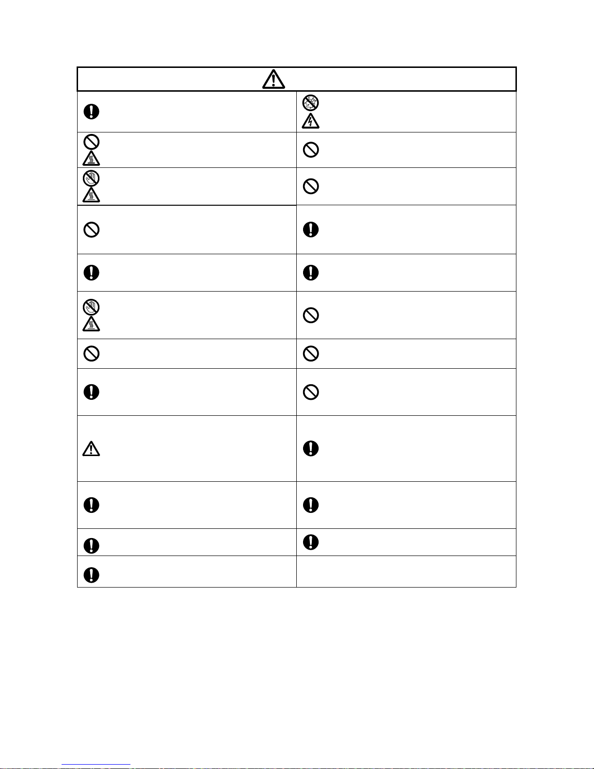
Caution
Before operation, thoroughly clean (flush) the
inside of the piping to remove foreign matter.
Otherwise, the piping system may be contaminated with
foreign matter, thus leading to an accident or a pump failure.
Do not expose the motor to water.
Otherwise, it may lead to an electric shock, electric leak,
failure, or other problems.
Do not put a cloth or other covering on the motor.
Otherwise, it may lead to overheating or ignition.
Do not place any obstacles around the product that
may hinder ventilation.
Otherwise, it may lead to a fire.
Do not touch the motor body while the pump is
running or immediately after the pump has stopped.
Otherwise, you may get burns from the hot surface.
Never run the pump dry (no-discharge operation) or
with insufficient amount of priming liquid.
Otherwise, it may cause damage to the sliding part of the
pump.
Do not run the pump with tools or other objects
placed on the unit.
Otherwise, it may lead to an injury or damage.
In the event of an alarm or abnormal condition that
cannot be resolved, immediately stop the
operation, turn off the power, and then contact Teral
or its service provider.
Otherwise, it may lead to an accident.
Be sure to install a strainer at the suction side of the
pump.
Otherwise, foreign objects may enter into the piping and thus
cause damage to the sliding parts of the pump.
Be sure to conduct inspection according to the
Maintenance checklist.
Otherwise, you cannot prevent potential failures, thus leading
to a higher risk of accidents.
Do not touch the motor if the liquid used exceeds
40 °C.
Otherwise, it may lead to a fire
Once you turn off the power, wait until the pump
stops completely. Do not restart the pump until it
does.
Otherwise, the main shaft may be subjected to an excessive
load, which makes the service life of the pump shorter.
Do not place any combustibles around the product.
Otherwise, it may lead to an injury or damage.
Minimize the frequency of startups and shutdowns
of the pump (Max. 5 times per hour).
Otherwise, it may lead to quick damage of the pump.
Ensure to install an overcurrent protective device.
The user is required by the technical standards for electrical
facilities to install one. Otherwise, it may damage the product,
thus leading to a fire or failure. It is also recommended to
install protective devices such as a groun d fau l t interrupter.
When you lift the product by hand, pay attention to
its weight. Do not allow a single person to lift a
product heavier than 15 kg.
Otherwise, it may put strain on the body, thus leading to an
injury.
Before lifting the product, refer to the catalog,
dimensional drawing, and other documents to
check the weight of the product. Do not lift the
product if its weight exceeds the rated load of the
hoisting devices.
Otherwise, the product may topple over or fall, thus leading to
an injury.
Whenever disassembly and inspection of the
pump, replace the packing and O-ring.
Otherwise, it may lead to liquid leakage.
Before disassembly, be sure to close the
suction/discharge valve and drain the
high-pressure water in the pump/piping.
Otherwise, the product may topple over or fall, thus leading to
an injury.
When the pump is not used for a long time, turn off
the main power and the pump shall be sufficiently
drained for storage.
Otherwise, it may lead to liquid leakage.
Align the shafts correctly.
Otherwise, It may lead to damage, vibration or noise.
Dispose of the product as industrial waste.
Take the companion flange out of the pump and
screw the pipes.
Otherwise, It may lead to damage or leakage.
1-3
Page 7
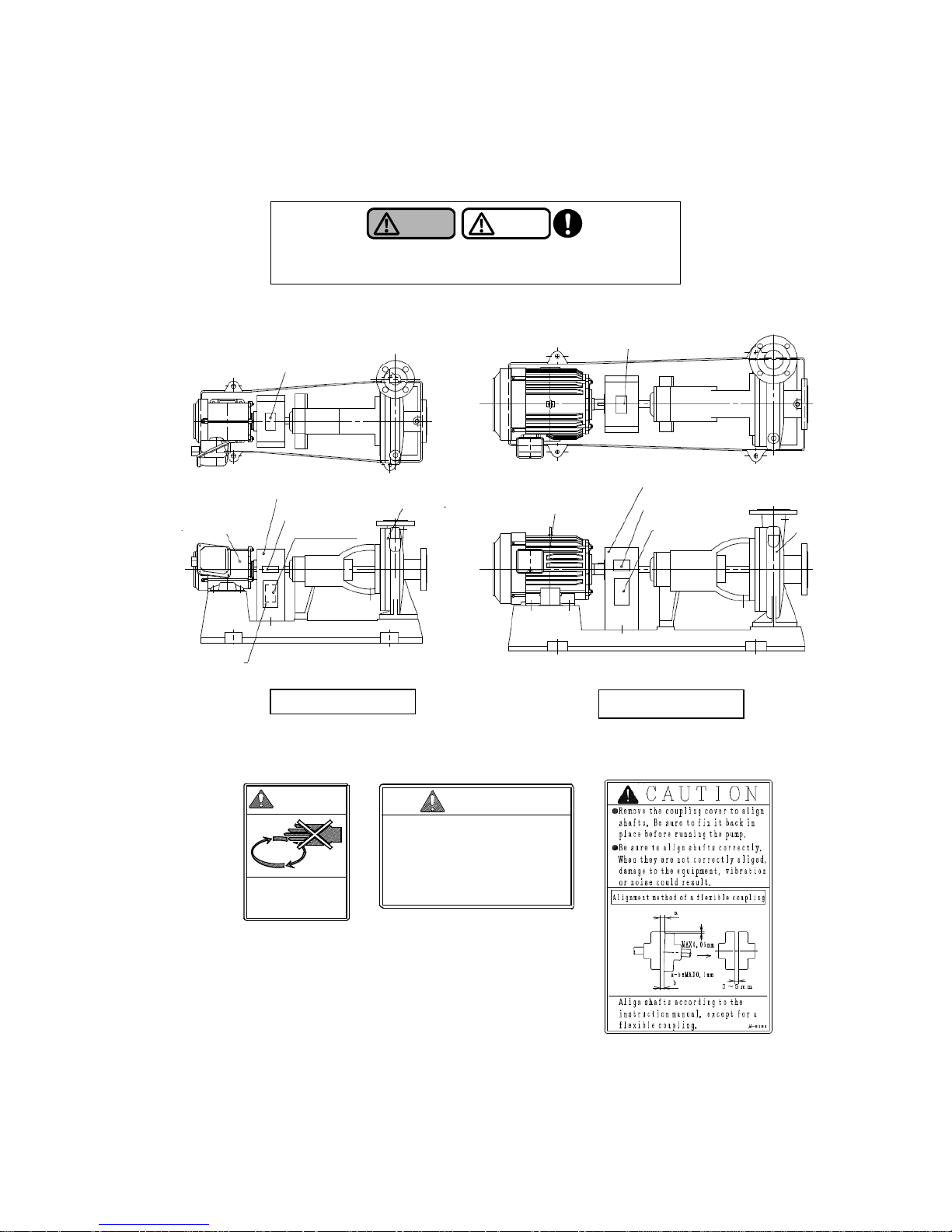
1.3 Location of warning labels and caution labels
The figure shows the locations of warning labels and caution labels. If these labels become dirty and
illegible or if they are peeled off, replace them with a new one.
Warning
Caution
Observe all the warnings and cautions affixed to the machine
as well as those described in this instruction manual.
Caution label 1
CAUTION
· Have installation, electrical work and repair
performed by specialist companies.
· The machine must only be operated and inspected
by persons who have received authorization from
the person in charge of machine management.
· Read the operation manual thoroughly, and follow
the instructions in it so that you use the machine
correctly.
M-5440-1
Caution label 2
*The figure shows a typical model.
Caution label 1
WARNING
Warning label
Rotating parts
Danger of injury!
Do not put hands
inside.
M-5424
Output 0.75kW and less
Output 1.5kW and over
Pump
Warning label
Caution label 1
Shaft coupling protective cover
Caution label 2
Moto
r
Pum
p
Warning label
Motor
Caution label 3
Shaft coupling protective cover
Caution label 2
1-4
Page 8
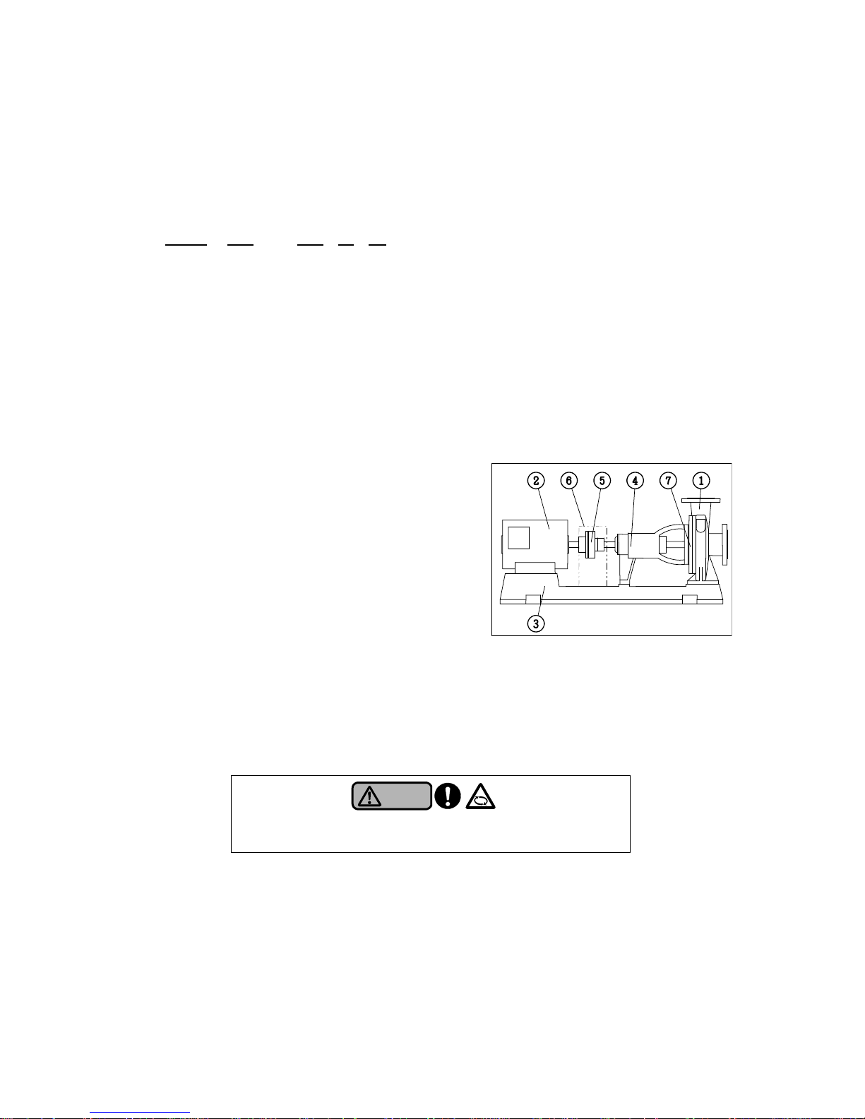
2. Configuration and overview of the pump
This chapter describes the standard specifications of the pump. If you have purchased a customized
product, some information in this chapter may not be applicable to your unit. Refer to the delivery
specifications for the details separately.
2.1 Model type description
LS2 50 x 40 A -e
① ② ③ ④ ⑤
① Model
② Suction
diameter
③ Discharge
diameter
④ Type
: LS2 (pole : 2P), LS (pole : 4P), LM (pole : 2P, number of stage : 2 stages)
: 50 mm
: 40 mm
⑤ Appended to the products with a built-in top runner ef ficiency (IE3 equivalent) motor
2.2 Part names and functions
① Casing
It connects the pipes. An impeller rotates
inside the casing to pressurize the liquid used.
② Motor
③ Common bed
④ Bearing case
It is an oil bath type and the sealed ball
bearing is housed in it.
⑤ Shaft coupling
This coupling connects the pump and motor
shafts,transmitting the power.It absorbs offset
between the centers of the two shafts.
⑥ Shaft coupling protective cover
⑦ Shaft seal part
It prevents water leakage from the shaft penetrating hole. Both of mechanical seal type and
gland packing type are available.
Warning
Be sure to put a shaft coupling protective cover during operation.
Failure to observe this may lead to an injury or damage.
*The figure shows a typical model.
2-1
Page 9
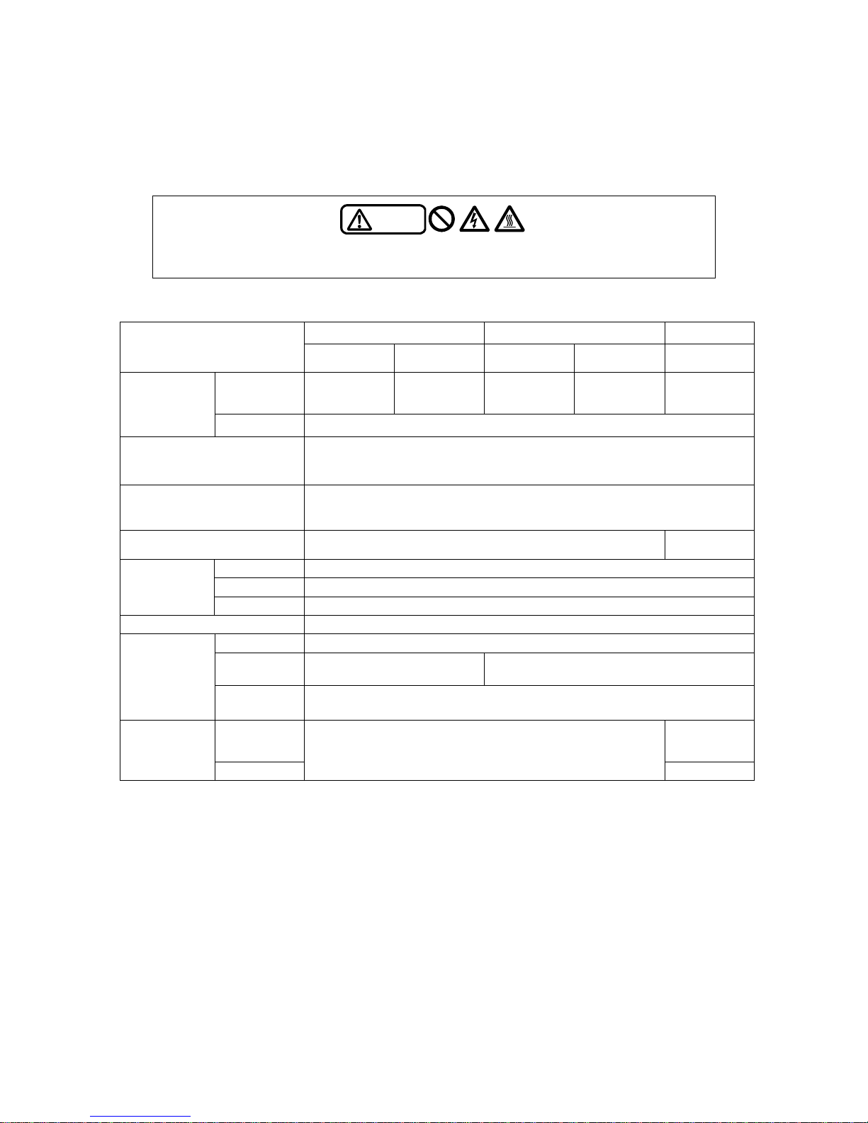
2.3 Standard specifications
If you have purchased our standard product, refer to the “Standard specifications” table. For details, refer to
the specifications including the dimensional drawing and the internal structure drawing. Also if you have
purchased a customized product with special specifications, refer to the specifications including the
dimensional drawing and the internal structure drawing.
Caution
Do not use this product under any conditions other than those provided in the specifications.
Failure to observe this may cause an electric shock, a fire, leaks, or failures.
・Standa rd specification s
LS2/LS2-e LS/LS2-e LM/LM-e
Model
Cast iron
Stainless
steel
Cast iron Stainless
steel
Cast iron
Quality
Fresh water
*1
Corrosive
liquid such as
acid, alkali
Fresh water
*1
Corrosive
liquid such as
acid, alkali
Fresh water
*1
Applicable
liquid
Temperature 0 to 90°C
Installation location
Indoors, height above sea level: 1,000m or less; ambient temperature: 0 to 40 °C ;
humidity: less than RH85% (no condensing); place not exposed to direct sunlight;
place without any corrosive gas, explosive gas, or vapor in the atmosphere
Total suction head *
2
(at water temperature of 20 °C)
Refer to the selection chart in the catalogue
Allowable boost pressure 0.59MPa or (1.37MPa-shutoff pressure), whichever is lower 0.29MPa
Impeller Closed
Shaft seal Gland packing (for special specification : mechanical seal)
Structure
Bearing Open ball bearing (oil bath type), Lubricant : Turbine oil #32
Material Refer to the specifications including the internal structure drawing
Type Refer to the specifications including the assembly drawing
Number of
poles
2P 4P
Motor
Power supply
*
3
50Hz: 3-phase 200V
60Hz: 3-phase 200V/220V
Suction
JIS 10K
conventional
flange
Flange
standard
Discharge
JIS 10K conventional flange
JIS 20K
* 1 Fresh water: 5.8-8.6 pH water without any contaminants (slurry and solids) and of which chloride ion
concentration does not exceed 200 mg/L. The water containing chloride ion exceeding 200mg/L may
cause corrosion. If the water contains a large amount of corrosive ions, it might not be used for the
product. Please contact to your nearest Teral office, if the water has a higher pH value or contains a
large amount of chloride ion, hydrogen sulfide ion, fluorine ion, bromine ion, and iodine ion, or it is the
special liquid.
* 2 The total suction head indicated in the catalogue shows the values when the water temperatu re is
20 °C. The maximum value of the total suction head decreases when the pump is used with warm
water. The total suction head shows the sum of suction height and suction pipe resistance.
* 3 Limit the fluctuations of the power voltage within ±10% of the rated voltage, and also limit the
fluctuations of the frequency between –5% and +3% of the rated value. Avoid continuous operation if
the voltage is not within ±5% of the rated value or if the frequency is not within ±2% of the rat ed value.
2-2
Page 10
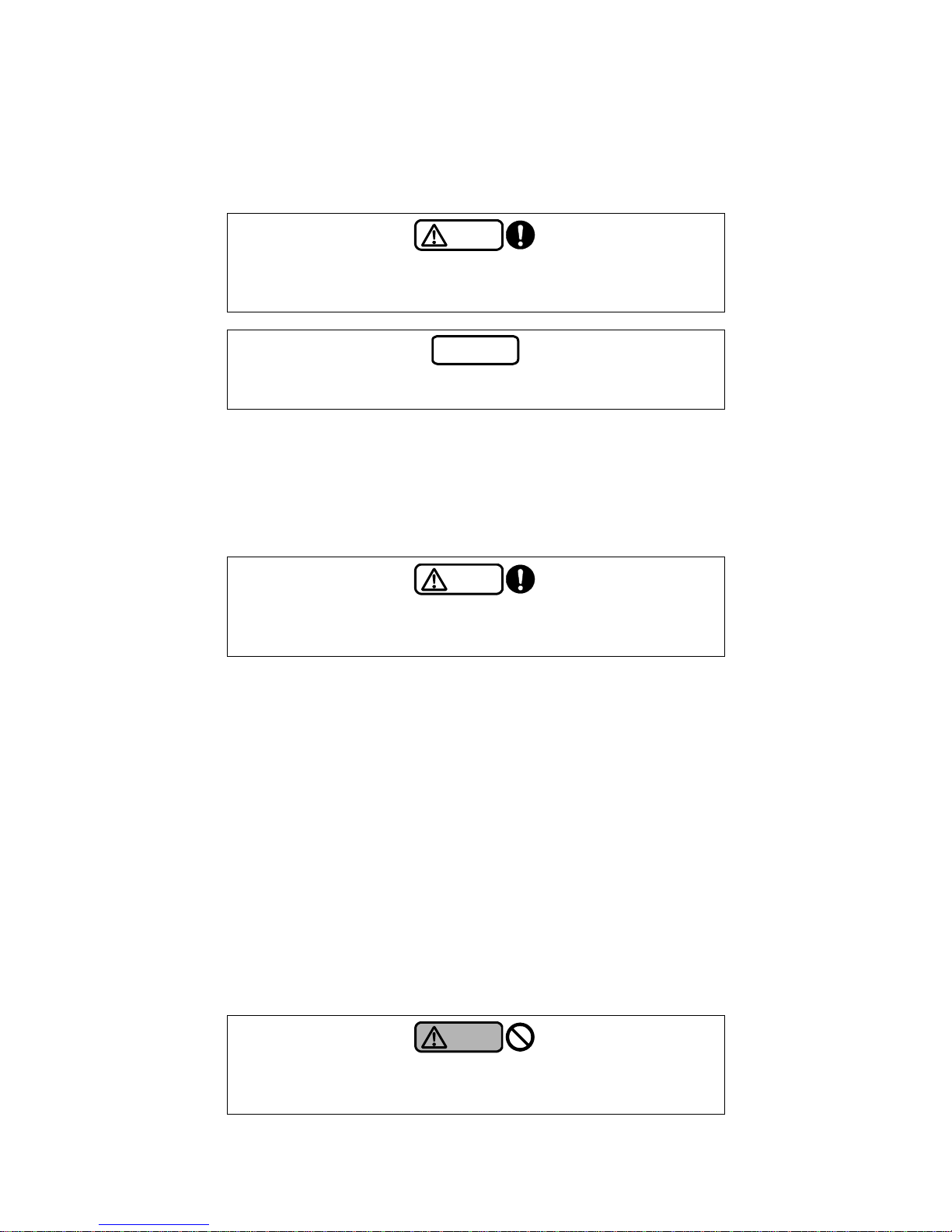
3-1
3. Installation
3.1 Before using the pump
Upon receiving the pump, check the following points first.
The container may greatly incline depending on its center of gravity.
Caution
Before unpacking, ensure that the delivered container is placed in the
correct orientation (not upside down). Pay special attention to nails
especially when opening a wooden crate. Otherwise, you may get injured.
Note
After the unpacking, ask the waste-disposal company to dispose of
packaging materials that are no longer necessary.
(1) Check the nameplate to verify that the delivered product is exactly what you ordered.
(2) No part of the product is damaged during transport ation.
(3) All fastening parts including bolts and nuts are securely tightened.
(4) All the accessories that yo u ordered have been delivered.
3.2 Precautions for installation
Caution
Observe the precautions for installation in the main text below. Failure to
observe this may cause failure or damage. It may also result in shortening
the service life of the unit.
(1) Install the product at a location where the following conditions are all satisfied:
・
A place shelt ered from wind and rain
The product is for indoor use. If it is used at outdoors, the place must be sheltered from wind
and rain, or specification change is required for outdoor use (special specificatio n). When
installing the product for outdoor use, the place must be preve nted water from directly entering
into the air vent hole of the oil feeding plug.
・
A well-ventilated place at an ambient temperature of 0°C to 40°C with minimum exposure to
dust and moisture
・
A place that is free from the exposure to a jet of steam and salt damage
・
A place wher e the pump cannot easily be accessed or operated by unauthorized persons
・
A place as close to the wa ter supply source as possible so that the suction pipe can be short
Install the pump so that the total suction head will comply with the requirement specifie d in “2.3
Pump specifications - Standard specifications.” However, the total suction head may be
required to be shorter than the requirement depending on the liquid temperature. In general,
boost operation is necessary when the liquid temperature is 70
°C
or more.
・
A place that is free from a se condary hazard in the event of liquid leakage.
Warning
Do not install the product in a place exposed to high temperature and
moisture. Failure to observe this may cause heating, ignition or electric
leakage.
Page 11
3-2
Caution
Install the product so that the total suction head (suction height + suction
pipe resistance) is as small as possible within the standard specifications.
Caution
Do not install the pump at an upward curve of piping (where air i s trapped).
Failure to observe this may cause the pump to run dry, and seize up the
sliding part in the pump.
(2) If the pump is use
d for hot water circulation through closed piping, fit the piping system with an
expansion tank, a safety valve, and other devices.
(3) If the product is used as a circulating pump, attach a sluice valve each to the suction and
discharge sides of the pump. It is not necessary to drain water out of the piping at the time of
inspection or repair of the pump.
(4) Using anchor bolts, fix the pump firmly on a level concrete foundation.
Note
Securely fix the pump in place with anchor bolts. Otherwise, it may lead to
abnormal vibration or other problems.
(5) To lift the pump, be sure to pass ropes or other lines through the underside of the common base.
Warning
Do not hoist the whole unit using the main shaft of the pump, the lifting
harness on the motor, or any other parts not intended for the purpose.
Warning
Before lifting the product, refer to the catalog, dimensional drawing, and
other documents to check the weight of the product. Do not lift the produ ct
if its weight exceeds the rated load of the hoisting devices.
Warning
Never use a pump or install part s to it while the pump is lifted. Otherwise,
the unit may fall, thus leading to an injury.
Caution
When lifting the product, pay attention to its center of gravity. Otherwise,
the product may topple over or fall, thus leading to an injury.
Caution
When lifting the pump by hand pay attention to its center of gravity and
weight. Do not allow a single person to lift a product heavier than 15kg.
Failure to observe this may put a burden on the body, thus leading to an
injury.
Page 12
3-3
(6) Ensure to provide a drain ditch around the pump.
(7) If the system could be exposed to the freezing temperature in winter, ensure to take measures to
prevent freezing in the pump room or to prevent the pump, sluice valves, piping, and other
devices from freezing.
(8) Use sound-insulating materials for door and walls of the pump room. Especially if there is a risk
that the noise may cause problem, take necessary measures against the noise.
(9) If the pumping liquid is cold, condensation may occur inside the motor while the pump is stopped.
Take measures to prevent condensation, for example, by installing the pump in a sufficiently dry
room or by heating and insulating the motor even when the pump is stopped.
(10) Carry out repair painting at a time interval suitable for the environment of use. Depending on the
humidity, condensation, and other conditions, rust may form on areas such as threaded parts,
worked areas, anticorrosive-coated sections.
(11) Do not put a cover or filter over the motor. Failure to observe this may raise the temperature inside
the motor, thus leading to produ ct damage, fire, or other problems.
3.3
Installation procedure
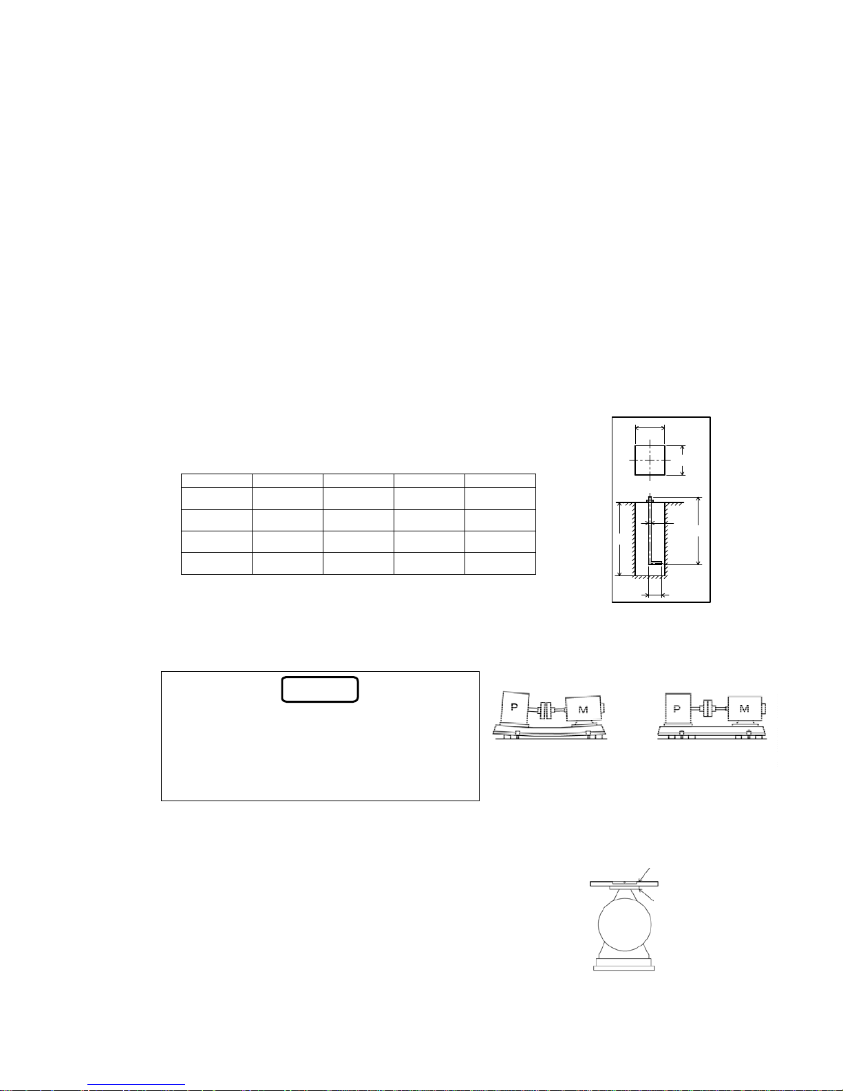
(1) The area and thickness of the foundation concrete must be large enough to withstand the pump
weight and the operating load.
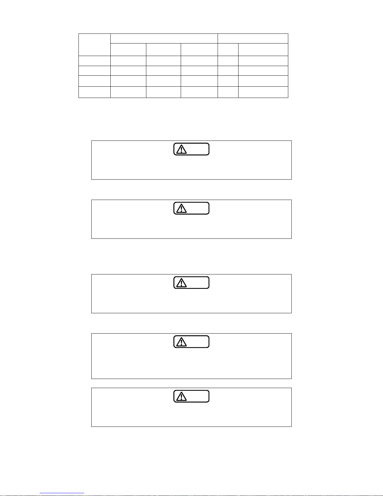
(2) Make foundation holes in advance, according to the drawing or the size of
the actual bolts.
Table - Dimensions of Foundation Bolts and Foundation Holes
FD FL FB Wa H
M10 200 45 100 250
M12 250 55 120 300
M16 315 70 150 370
M20 400 90 190 450
(3) Ensure that the top surface of the foundation concrete is level, and that the
concrete is sufficiently cured before the installation of the pump.
H
Wa
FB
FD
Wa
FL
(4) Place the pump on the fou
ndation concrete. At that time, drive a square steel plate and metal
wedges between the common base and the foundation concrete to provide a clearance (about 10
mm to 30 mm) for mortar to be poured into.
Note
The metal wedges are used to adjust the horizont al
level of the pump, and also to sustain the pump
weight and the operating load. Use as thick a wedge
as possible to reduce the total number of pieces.
Uniformly place them close to the foundation bolts so
that the loads are evenly supported.
Incorrect
Correct
(5) Fix foundation bolts to the common base with nuts so that they are suspended in mid-air at the
center of each foundation hole.
(6) Place a level on the flange surface to check the horizontality of the
surface. If it is not horizontal, adjust it with metal wedges.
Discharge
flange
Pump
Level
(7) Once the horiz
ontality and verticality are achieved, lay mortar into
the foundation holes, the clearance under the common base, and
the area around the common base. When the mortar has set
completely after a few days, tighten the foundation bolts. (At that
time, ensure to tighten the nuts evenly and gradually.)
Page 13
3-4
(8) Be sure to align the shafts correctly.
Although the shaft is aligned at the factory before shipment, it could get misaligned during
transportation or installation (at fastening the anchor bolts). Check the alignment and re-align it
after the installation is complete.
3.4 Coupling alignment procedure
Warning
Be sure to turn off the power switch before starting alignment. The pump
may be unexpectedly activated and cause an injury.
Warning
Remove the shaft coupling cover when carrying out alignment. Before
operating the pump, however, be sure to fit the cover back on. If the pump
is operated without the cover, you may get caught in the machinery and
injured.
Caution
Improper alignment may lead to machine damage, vibrations, or noise.
Ensure to achieve accurate alignment.
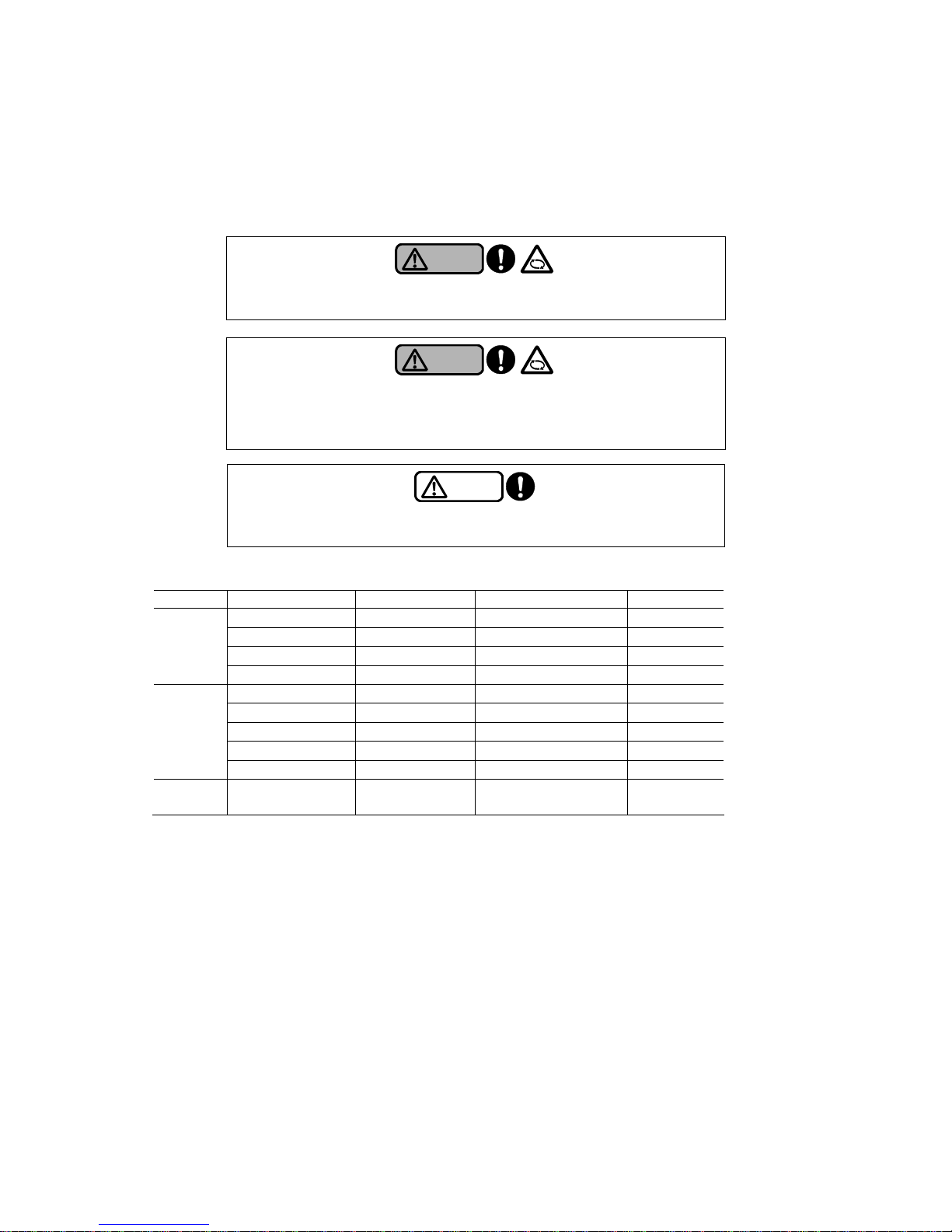
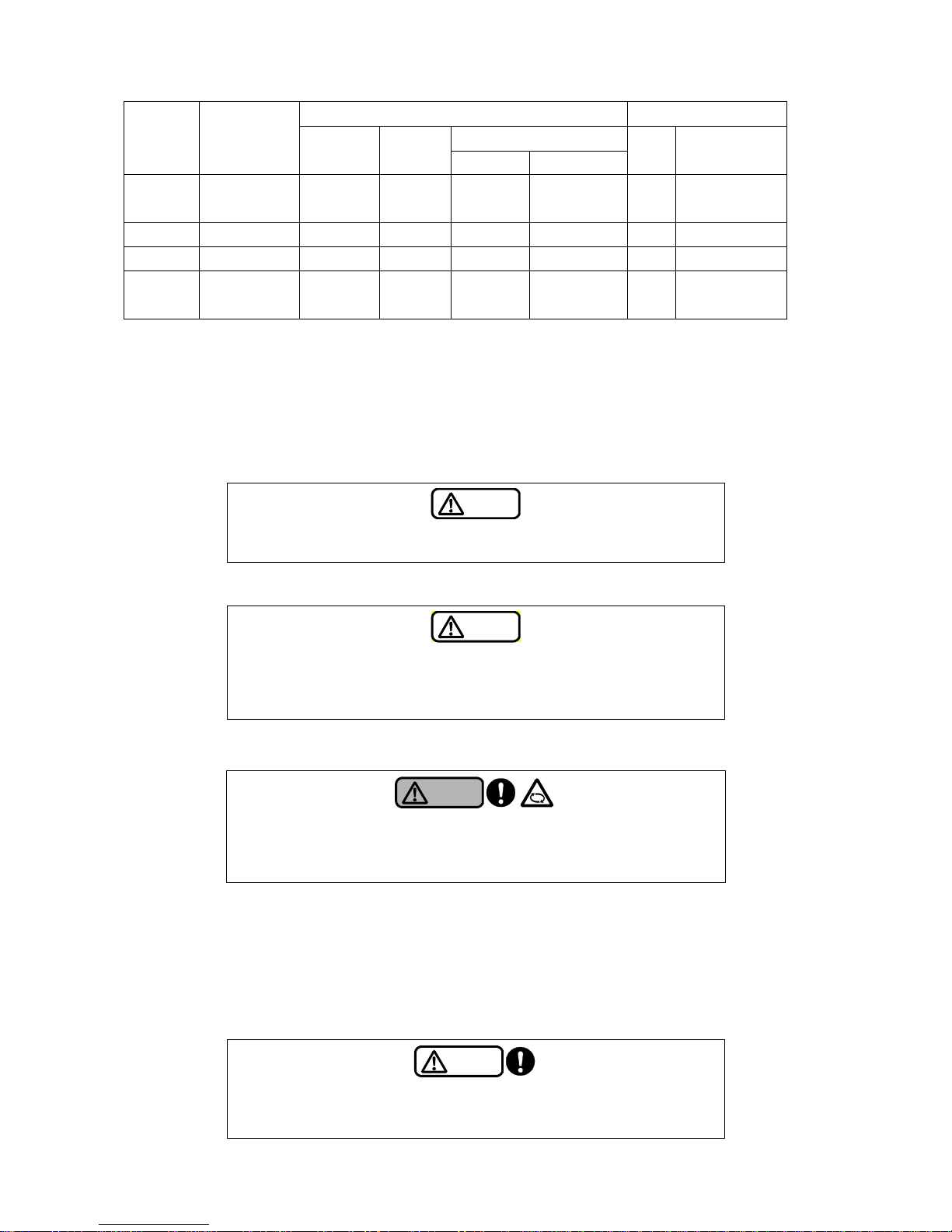
Coupling appl
ication table
Model Rated output Coupling model Coupling type Development
5.5kW and less CF-A-008 CF – A (Cylindrical hub) Fig. 3.4.1-1
7.5kW CF-A-012 CF – A (Cylindrical hub) Fig. 3.4.1-1
11kW – 18.5kW CF-A-022 CF – A (Spacer hub) Fig. 3.4.1-2
LS2
LS2-e
22kW and over CF-A-028 CF – A (Spacer hub) Fig. 3.4.1-2
5.5kW and less CF-A-008 CF – A (Cylindrical hub) Fig. 3.4.1-1
7.5kW CF-A-012 CF – A (Cylindrical hub) Fig. 3.4.1-1
11kW – 15kW CF-A-022 CF – A (Spacer hub) Fig. 3.4.1-2
18.5kW – 30kW CF-A-028 CF – A (Spacer hub) Fig. 3.4.1-2
LS
LS-e
37kW and over All sorts of AB AB Fig. 3. 4. 2
LM
LM-e
Total output All sorts of AB AB Fig. 3. 4. 2
Page 14
3-5
3.4.1 Alignment (CF-A type coupling)
(1)
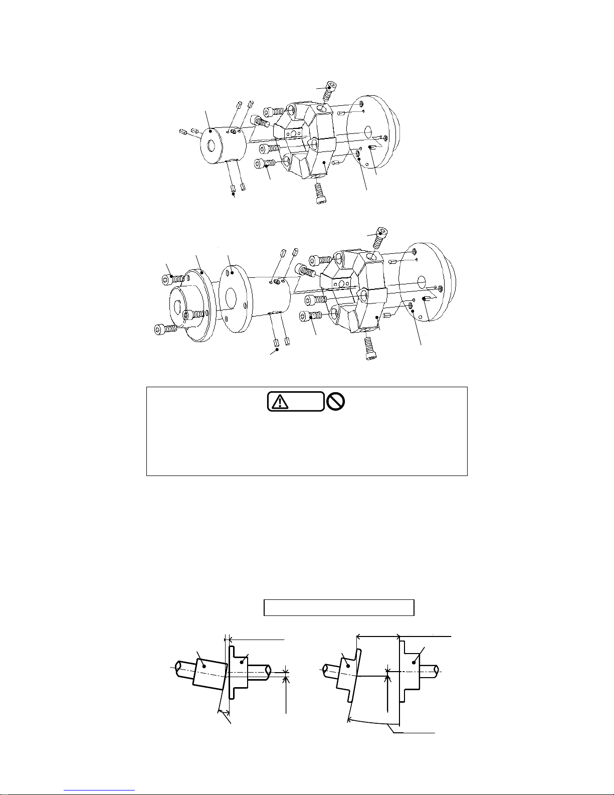
Remove the bolt B (radial
direction) and then remove the bolt A (axial direction).
(2) If a rubber body is mounted on a cylindrical hub, it would make difficult to check the alignment.
Keep the rubber body inserted in the pump shaft and slide it to the pump side.
For CF-A (spacer hub type), remove the bolt C and then remove the rubber b ody.
(3) Perform the alignment work as accurately as possible adjust so that the difference between
coupling centers is within the allowable value.
Use a dial gauge, a taper gauge, and a parallel ruler for precise measurement s.
Caution
The dimensions to push the cylindrical hub (spacer hu b) and the flange
hub against the shaft end change depending on the pump model. Whe n
removing the cylindrical hub (spacer hub) and the flange hub, m ake sure to
check the dimensions to push them before disassembly.
Also make sure to adjust the proper dimensions to push the hub.
円筒ハブ
電
動
機
側
ポ
ン
プ
側
スプリングピン
ボル
ボルトB
トA
方向)(軸
(ラジアル方向)
Bolt B
(Radial direction)
Cylindrical hub
スプリングピン
フランジハブ
ゴム体
Spring pin
Bolt A
(Axial direction)
Rubber
body
Flange hub
Spring pin
Motor Pump
side side
Fig. 3.4.1-1 CF-A (Cylindrical hub type)
ボルトB
ラジアル方向)
ボルトA
軸方向)(
(
Bolt B
(Radial direction)
ゴム体
電
動
機
側
スプリングピン
フランジハブ
ポ
ン
プ
側
スプリングピン
スペーサハブフランジハブ
ボルトC
Bolt C
Flange hub Spacer hub
Pump
Motor
side
side
Spring pin
Rubber
body
Bolt A
(Axial direction)
Flange hub
Spring pin
Fig. 3.4.1-2 CF-A (Spacer hub type)
CF-A型芯出し基準値
120±5mm以下
4±4mm以下
フランジハブ
(軸方向変位)
(軸方向変位)
フランジハブ フランジハブ
0.
(
5mm以
偏芯
下
)
0.5
(偏芯)
1°以下
(偏角)
CF-Aスペーサハブタイプ
mm以下
1°以下
(偏角)
円筒ハブ
CF-A円筒ハブタイプ
Flange hub
Flange hub
CF-A cylindrical hub type
4±4 mm or less
0.5 mm or less
0.5 mm
or less
(Parallel)
1°or less
(Angular)
(Parallel)
CF-A spacer hub type
(Axial)
Cylindrical hub
120±5 mm or less
(Axial)
Flange hub
CF-A type allowable amount of misalignment
1°or less
(Angular)
Page 15
3-6
Allowable amount of misalignment Bolt / Nut Coupling
model
Parallel
ε (mm)
Angular
θ°
Axial
L(mm)
Size Tightening torque
(N・m)
CF-A-008 0.5 1 4±4 M10 49 – 54 (bolt A/B)
CF-A-012 0.5 1 4±4 M10 49 – 54 (bolt A/B)
CF-A-022 0.5 1 120±5
M12
M10
85 – 94 (bolt A/B)
49 – 54 (bolt C)
CF-A-028 0.5 1 120±5
M14
M12
130 - 150 (bolt A/B)
85 – 94 (bolt C)
(4) After confirming that mounting misalignment is within the allowable amount, return the rubber
body onto the cylindrical hub.
For CF-A (spacer hub type), tighten the bolt C to lock the sp acer hub and insert the rubber body.
Caution
When mounting a rubber body on the cylindrical hub, wipe off the grease
on the mounting surface. The oil composition might have adverse ef fects
on the rubber body.
(5) Chec
k that the spring pin is firmly pushed into the cylindrical hub (spacer hub) and the flange h ub.
Caution
Ensure that the spring pin is firmly pushed into the hub before mounting the
rubber body. Failure to observe this may cause damage to the equipment
or vibration and noise.
(6)
Asse
mble by
first tightening the bolt A (axial direction) to lock the rubber body into the flange hub,
and then tightening the bolt B (radial direction) to lock the rubber body into the cylindrical hub
(spacer hub).
Caution
When mounting the rubber body onto the cylindrical hub (spacer hub),
screw each bolt in by two threads each and then tighten. In case tightening
either one bolt first, it might be unable to assemble them.
(7) Ti
ghten the bolts evenly with a torque wrench to the prescribed tightening torque.
Caution
In case tightening the bolt B (radial direction) to lock the rubber body into
the flange hub first, the rubber body may be deformed due to the friction of
bolt seat face. Make sure to tighten the bolt A (axial direction) first to lock
the rubber body, and then tighten the bolt B (radial direction).
Caution
Bolts for mounting are given a microcapsule coating in blue color. Do not
use any other type of bolts. Moreover , never use an anaerobic liquid
adhesive because it might have adverse effects on the rubber body.
(8)
Install the sh
aft coupling protective cover.
Page 16
3-7
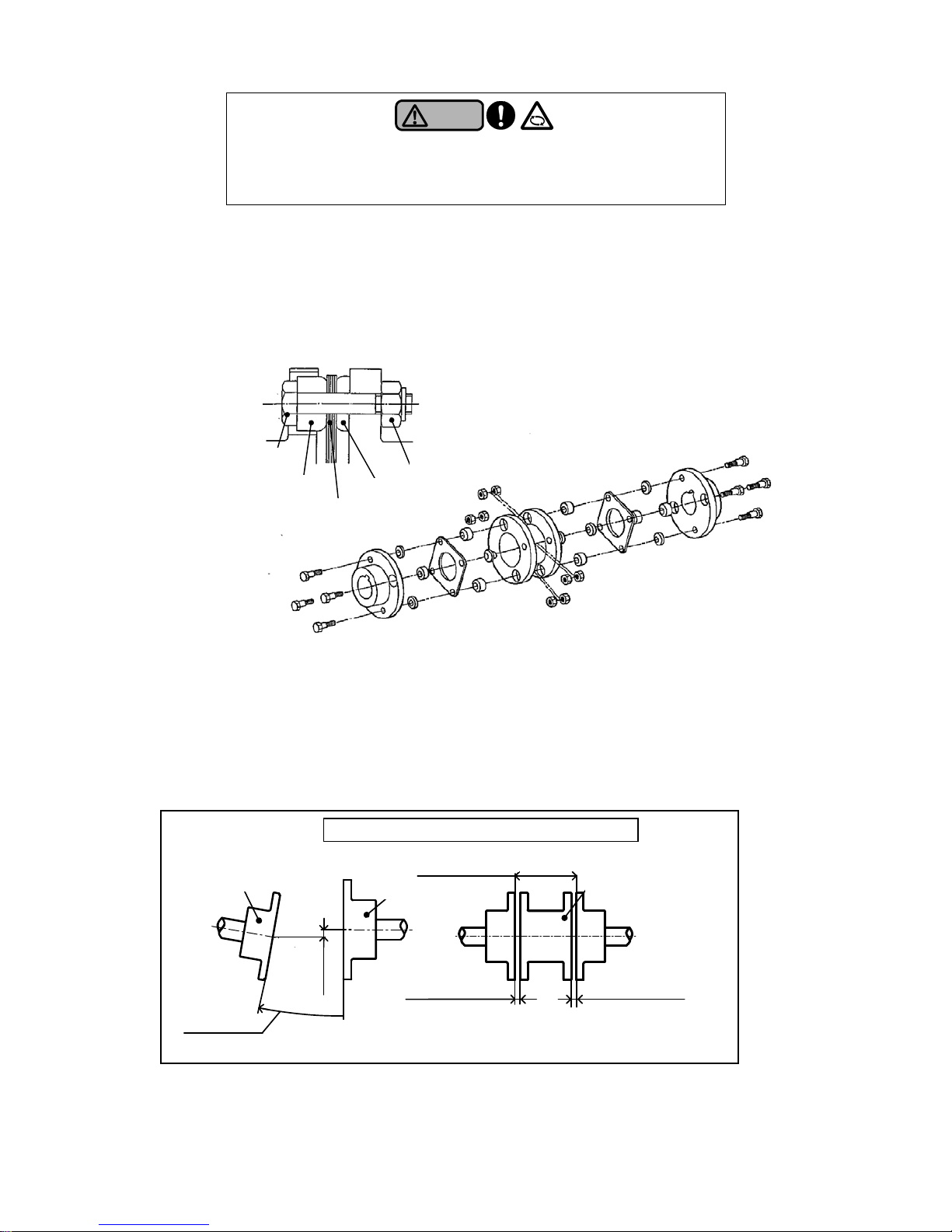
Warning
Remove the shaft coupling cover when carrying out alignment. Before
operating the pump, however, be sure to fit the cover back on. If the pump
is operated without the cover, you may get caught in the machinery and
injured.
(9)
When
alignment is complete, pour mortar into the anchor bolt holes, the gap under the common
bed, and the area around the common base. When the mortar has fully cured, tighten the anchor
bolts.
3.4.2 Alignment (AB type coupling)
(1)
Loosen the n
ut and then remove the spacer hub.
(2) Perform the alignment work as accurately as possible adjust so that the difference between
coupling centers is within the allowable value.
Use a dial gauge, a taper gauge, and a parallel ruler for precise measurements.
ワッシャA
ワッシャB
ナット
エレメント
ボルト
Bolt
Washer A
Element
Washer B
Fig. 3.4.2 AB type coupling
Nut
AB型芯出し基準値
εmm 下以
(偏芯)
L±0.5mm以下
(軸方向変位)
0.25°以下
(偏角)
フランジハブ
フランジハブ
AB型カップリング
AB型カップリング
E±0.25mm以下
スペーサハブ
E±0.25mm以下
A
B type coupling
A
B type coupling
A
B type coupling
0.25°or less
(Angular)
L±0.5 mm or less (Axial)
Spacer hub
Flange hub
A
B type e amount of misalignment coupling allowabl
Flange hub
ԑ
less
ra el)
mm
or
(Pa ll
E±0.25mm or less
E±0.25 mm or less
Page 17
3-8
Allowable amount of misalignment Bolt / Nut
Axial
Rated
output
Coupling
model
Parallel
ε (mm)
Angular
θ°
L(mm)±0.5 E(mm)±0.25
Size
Tightening
torque
(N・m)
37kW,
45kW
AB-25ZN-140 0.5 0.25 140 11.7 M10 41.2
55kW AB-30ZN-140 0.5 0.25 140 11.7 M10 71.5
75kW AB-35ZN-140 0.5 0.25 140 16.8 M12 71.5
90kW –
132kW
AB-35ZN-180 0.7
0.25 180 16.8 M12 71.5
Note) The
AB type coupling model corresponding to each rated output is a typical model. The coupling
model is subject to change according to the pump specification.
(3) After mounting misalignment is within the allowable amount, insert the washer A so that the
curved surface of the washer A fits to the element. Next, insert the element.
(4) Insert the washer A to the other bolts in a similar way. Next, insert the washer B from the spac er
side so that the curved surface washer B fits to the element, and install the nut. Tighten the nuts
alternately on opposite sides to ensure they are tightened evenly.
Caution
When mounting the spacer, the spacer must be supported in parallel so as
not to damage the connected elements..
(5) Ti
ghten the bolts evenly with a torque wrench to the prescribed tightening torque.
Caution
In case tightening torque is not uniform, the variation may occur in the gap
(dimension E) between the spacer hub and the flange hub, which may
damage the connected elements. Make sure to tighten the bolts evenly
with a torque wrench.
(6)
Inst
all the sh
aft coupling protective cover.
Warning
Remove the shaft coupling cover when carrying out alignment. Before
operating the pump, however, be sure to fit the cover back on. If the pump
is operated without the cover, you may get caught in the machinery and
injured.
(7)
When alignment is complete, pour mortar into the anchor bolt holes, the gap under the common
bed, and the area around the common base. When the mortar has fully cured, tighten the anchor
bolts.
3.5 Precautions for piping work
Caution
Before piping work, remove the protective seals attached to the suction
port and the discharge port of the pump. Running the pump with those
seals attached may damage the pump and the piping.
Page 18
3-9
Caution
Be sure to install a strainer at the suction port of the pump. Otherwise, the
piping may be contaminated with foreign objects, thus damaging t he pump
and the piping.
Caution
Do not forcibly screw a pipe into the pump with the companion flange
attached to the pump. The pump may be damaged.
(1) Remove the prote
ction seal attached to the suction side and the discharge side of the pump
casing.
(2) Be sure to provide pipe supports so that the weight of pipes is not applied directly to the pump
main body.
Caution
Be sure to provide pipe supports for the pipes. Otherwise, the main shaft
may be displaced from the center , thus leading to the equipment damage,
vibration, or noise.
(3) The suction p
ipe must be made as short and straight as possible.
(4) Bends must be as far from the suction port of the pump as possible with maximum bend radius.
(5) Carefully attach joints and other parts to the suction pipe to block air suction.
(6) The suction piping should be corresponding to or larger in diameter than the pump port (a size
larger as a guide). In case, for lifting operation, you use a suction pipe with larger diameter than
that of the pump suction port, attach an eccentric reducer to prevent air from being trapped. Also if
you use a suction pipe with smaller diameter than that of the pump, it may cause cavitation.
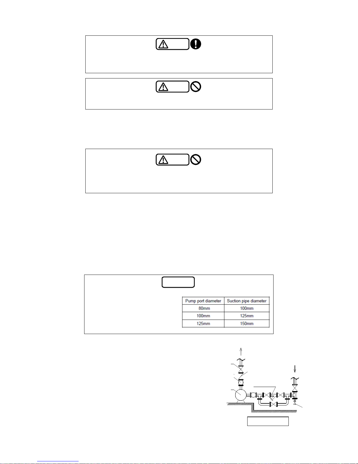
Note
For the models with pump suction
diameter of 80, 100, and 125mm,
the suction piping should be a size
larger in diameter than the pump. If
you use a suction pipe with smaller
diameter than that of the pump, it
may cause cavitation.
Discharge
(7) For boost op
eration
・ Be sure to attach a sluice valve to the suction pipe.
・ Install a strainer at the suction side of the pump to
block the entrance of foreign matter and other
objects (such as cutting chips, sand, rust, and scale)
to the pump. (Recommended mesh size for the
strainer: 40 mesh for normal use, 80 mesh for
cleaning)
Sluice valve
Suction
Check
valve
Vibration
isolation joint
Strainer
Pump
Drain valve
Construction example
Page 19
3-10
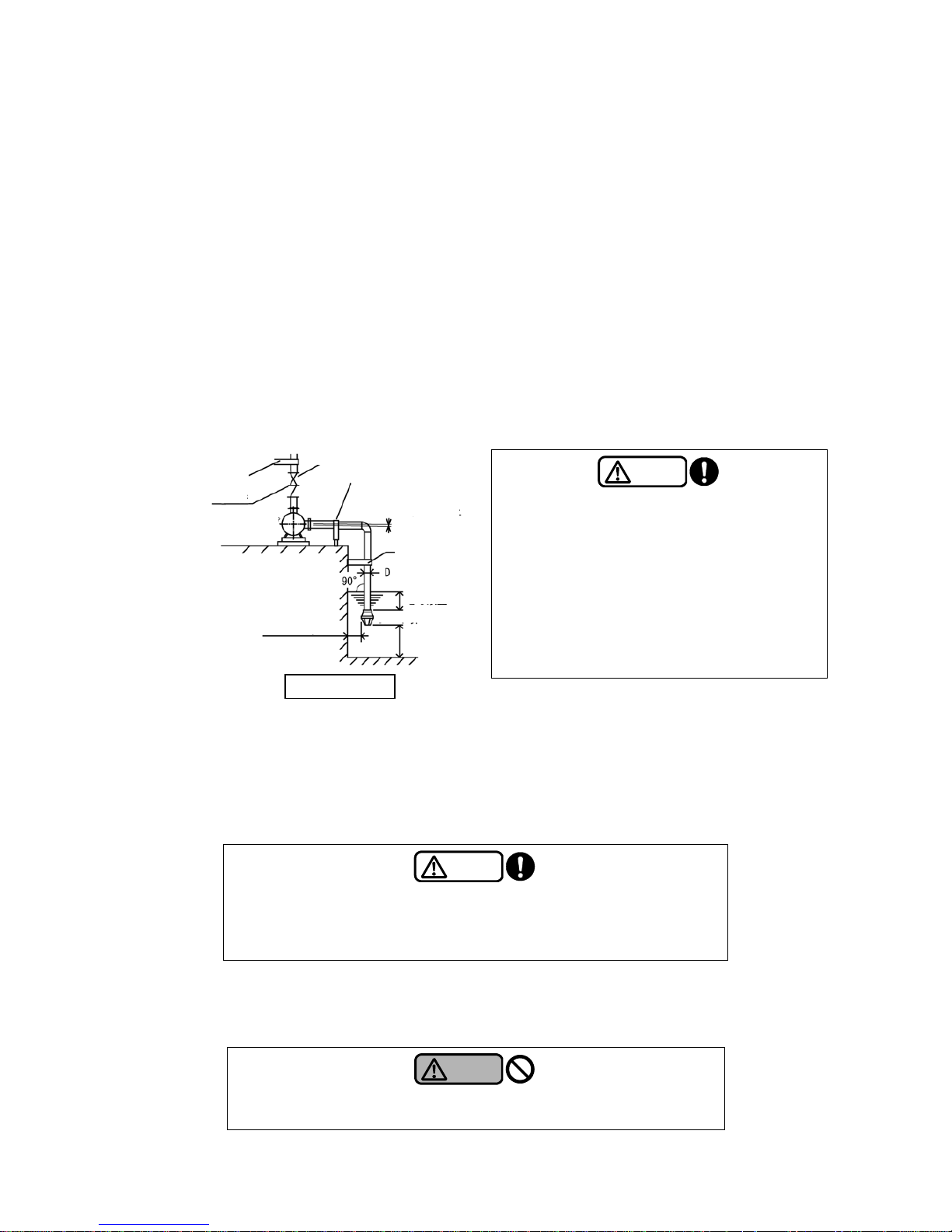
(8) For lifting operation
・ The suction pipes should be as short as possible with minimum ben ds. Do not attach a sluice
valve to the suction pipes. Do not install the piping with a shape of upward bend (i.e. providing
the piping with a rising gradient and then a descending gradient).
・ To prevent air from being trapped inside the suction pipe, provide a rising gradient (at least
1/100 degrees) leading up to the pump.
・ If you use a suction pipe whose bore is larger than that of the suction port of the pump, use an
eccentric reducer to prevent air from being trapped. The diameter of the suction pipe can be up
to 2 sizes larger than that of the pump. (e.g. If the suction port bore of the pump is 40A, the
suction pipe bore must be 50A or 65A.) If the diameter of the suction pipe is too large, the foot
valve might not open or bubbles may easily generate inside the suction pipes due to the
increased amount of the dissolved oxygen.
・ Attach a foot valve with a strainer to the end of the suction pipe to prevent entry of foreign
objects. Immerse the foot valve in water and set it at a depth of at least twice the diameter of the
pipe from the surface of water to prevent the suction of air. In addition, ensure that it is set
above 500 mm or more from the bottom of water.
Sluice valve
Min. 2D
Support
Construction example
Check
valve
Support
Foot valve
Support
Support
Min. 500mm
1 to 1.5D or larger
Gradient
Min. 1/100
Pump
Caution
In case of using a foot valve:
・ Properly install the foot valve vertically. If the
valve is not vertical, it does not open or close
properly, which comprises the function of the
foot valve.
・ Immerse the foot valve in water and set it at a
depth of at least twice the diameter of the pipe
from the surface of water to prevent the suction
of air. In addition, ensure that it is set above
500 mm or more from the bottom of water.
(9)
Atta
ch a sluice valve and a check valve to the discharge pipes. If water hammer may occur, attach
a buffer type check valve.
(10) If there is an upward curve in the discharge pipe, ensure that air can be vented from the section.
(11) If two or more pumps are used for lifting operation, every pump should have its own separate
suction piping.
Caution
If two or more pumps are used for lifting operation, every pump should have
its own separate suction piping. Otherwise, air may be sucked from the
inactive pump during single-pump operation, thus preventing water from
being pumped.
(12) If you t
ake heat insulation measures for the pump, be sure to avoid the motor section. Otherwise,
the motor may heat up and ignite. Furthermore, since the mechanical seal needs to be replaced
periodically, install detachable insulation for it.
Warning
Never install heat insulation to the motor section. Otherwise, the motor
may heat up and ignite.
Page 20
3-11
(13) On completion of the piping work, be sure to clean the inside of the receiver tank. Pay attention
not to contaminate the system with foreign matter.
(14) The shaft could get misaligned during installation due to the piping weight or fastening work of
anchor bolts. Check the alignment and re-align it after the installation is complete, referring to “3.4
Coupling alignment procedure.”
Caution
Improper alignment may lead to machine damage, vibrations, or noise.
Ensure to achieve accurate alignment.
3.6 Precautions for wiring work
Warning
Use high-quality wiring equipment and devices, and carry out wiring work
safely and securely according to the technical standards for electrical
facilities, as well as the indoor wiring regulations.
Only qualified personnel such as licensed electrical engineers are allowed
to carry out electrical wiring work. Unqualified persons are prohibited by
law to carry out wiring work, and it is very dangerous.
Warning
Securely connect the terminals of the power cable. Loose terminals may
cause the motor to run in open-phase condition, thus leading to motor
burnout.
Warning
Be sure to install a ground fault interrupter dedicated to the unit for the
power supply source. Failure to observe this may cause electric shock or
fire.
(1) Be sure to install a ground fault interrupter and an overload protection device on the primary
power side of the pump.
* When switching from an IE1 motor-equipped product, it is necessary to verify the applicability of
its ground fault interrupter and overload protection device. The starting current of Top Runner
efficiency (equivalent to IE3) motor-equipped products tends to become higher than that of
standard efficiency (IE1) motor-equipped products. If you have any questions, contact your
nearest office of Teral.
Note
When switching from an IE1 motor-equipped product, it is necessary to
verify the applicability of its protection device on the primary side of the
pump.
Failure to observe this may cause the protective device to trip on startup.
(2) Be sure to attach a ground wire to prevent an electric shock.
Connect the ground wire to the ground terminal inside the terminal box of the motor.
Page 21
3-12
Warning
Be sure to attach a ground wire to the motor and perform grounding work.
Warning
Connecting a ground wire to gas pipe or water pipe is illegal and extremely
dangerous.
(3) Pass the power cable through a metal tube or a metal conduit for shielding, and connect a ground
wire to the outer surface of the tube.
Caution
Do not install two or more different cabl es or control wires in one pipe or
duct.
(4) Limit the fluctuations of the supply voltage within ±10% of the rated voltage, and also limit the
fluctuations of the frequency between –5% and +3% of the rated value. Although you can run the
pump in these ranges, avoid continuous operation if the voltage is not within ±5% of the rated
value or if the frequency is not within ±2% of the rated value.
Even if the power fluctuations fall within the allowable ranges, the pump characteristics, motor
characteristics, and the temperature rise of the motor may differ from those at the rated voltage
and frequency.
(5) Precautions for using the inverter drive
• Ensure that the electric current during operation does not exceed 90% of the rated value.
• Ensure that the minimum frequency is set to 20Hz.
(Contact us if you need to run the drive at 20Hz or lower.)
• Do not use the inverter to drive a motor equipped with a self-protecting device.
• When driving a 400V-class motor, contact your nearest office of Teral. In some cases it might
be necessary to take measures for inverter surg e.
• An inverter-driven motor generates a magnetic sound which may be annoying compared with
the drives using commercial power supply.
• Although this magnetic sound does not adversely affect the quality of the motor , some
inverters allow the user to adjust the tone by changing the carrier frequency. However,
changing the frequency may reduce the allowable output of the inverter. Pay particular
attention when selecting the inverter.
• If the pump and motor produce resonance during normal operation, do not run them in the
range of the rotation speed.
Caution
Do not run the pump at a frequency exceeding 60 Hz (50 Hz for models dedicated to
50Hz). Failure to observe this may overload the motor, causing it to burnout. If the models
dedicated to 60Hz are run at 50Hz, the performance will deteriorate.
Page 22
4-1
4. Operation
4.1 Check items before test operation
4.1.1
Check items related to the electrical system
Warning
Before changing the wiring, be sure to turn off the main power supply.
Otherwise, you may receive an electric shock.
Warning
Do not use the product at any voltage other than the rated value.
A fire or electric shock may occur.
(1) Check that the equipment is correctly wired.
(2) Check that the terminals are securely connected.
(3) Check that the equipment is securely grounded.
(4) Check that the setup value of the overload protection device is consistent with the rated current
value of the motor.
4.1.2 Check items related to the pump
Caution
Do not put a cover or a filter over the motor. The temperature may rise
inside the motor, thus leading to failures.
Caution
Do not allow a large amount of foreign matter to enter the pump. Failure to
observe this may cause damage to the sliding parts (e.g. bearings) inside
the pump, leakage or unusual noise.
Caution
Ensure that a strainer is installed at the suction side of the pump
(Recommended strainer mesh: 40 mesh for normal use, 80 mesh for
cleaning). Foreign matters may enter the pump and cause damage to the
sliding parts (such as bearings, mechanical seal) in the pump, leakage or
unusual noise.
(1) Check that the gland packing is correctly installed.
(2) Be sure to close the sluice valve on the suction and discharge sides of the pump to drain the water
inside the pipes by natural drainage or other methods.
(3) Rotate the pump shaft by hand to check smooth rotation. Grip the coupling or the shaft by hand to
rotate the shaft. If the rotation is stiff or not uniform, there may be some rust or foreign matter
inside the pump. Inspect the pump in such a case.
Page 23
4-2
Warning
Before rotating the main shaft by hand to check it, be sure to turn off the main
power. An unexpected start of the pump may cause an accident.
(4) If the sluice valve is installed on the suction side, fully open the valve.
(5) Prime the pump until water overflows from the priming funnel or the priming port. At that time,
loosen the air vent cock to release air from the pump.
Warning
When priming the pump (air venting), prevent the damage of the motor and
parts from the spouting water. When you pump hot water, be careful not to get
burns.
Warning
For pumps circulating heated water, do not carry out the above procedure with
bare hands because hot water may spout out of the air vent cock, thus leading
to burns.
Caution
Never run the pump dry (operation without priming). Failure to observe this
may cause the sliding parts inside the pump to seize up.
(6) Check that the alignment of the shaft. Re-align it, if necessary, referring to “3.4 Coupling
alignment procedure.”
4.2 Running the pump (test operation)
Warning
Do not operate the pump if any abnormal condition is observed or if there is
anything wrong with the parts, component s, and others during the check
before test operation. Failure to observe this may cause an injury, failure,
accident, or other problems.
Warning
Be sure to put a shaft coupling protective cover during operation. Failure to
observe this you may cause an injury.
Warning
Be sure to attach the cover of the terminal box of the motor. Failure to observe
this may cause an electric shock.
Warning
If the liquid used exceeds 40°C, do not touch the pump. Failure to observe this
may cause an electric shock.
Page 24
4-3
Caution
Do not run the pump dry, and do not allow a large amount of air or foreign
matter to enter the pump. Failure to observe this may cause damage to the
sliding parts (bearings, etc.) insi de the pump, disabilit y of pumping, leaka ge o r
unusual noise. It may also heat the pump, thus leading to burns.
(1) Check the rotation direction of the pump by turning ON and OFF the power switch once or twice.
Normal rotation is clockwise when viewed from the motor side.
If the pump shaft rotates in reverse, swap two of the three wires of the power cable.
Caution
Never check the rotation direction by running the pump dry. Running the
pump dry even for a short time may cause damage to the sliding parts (e.g.
bearings, mechanical seal) inside the pump, leakage or unusual noise.
Caution
Do not run the motor in reverse because it may cause a failure.
(2) Turn on the power to start the pump.
(3) During the initial period of pump operation and circulation, gradually open the sluice valve on the
discharge side to circulate liquid at a flow rate (flow velocity) higher than the normal operation.
After this circulation cleaning is complete, clean the strainer.
(4) Adjust the sluice valve on the discharge side so that the specified pressure is achieved.
Warning
Do not perform long hours of no-discharge operation continuously.
Failure to observe this may increase the temperature in the pump, resulting
in an unexpected failure.
(5) As a guide, limit the frequency of the startups and shutdowns to about five times an hour.
Caution
Minimize the frequency of startups and shutdo wns of the pump because
frequent startups and shutdowns may damage the p ump sooner than
usual. Do not start the pump more than five times an hour or so.
(6) In the event of a power failure during operation, be sure to turn off the power.
Warning
In the event of a power failure, be sure to turn off the main power.
The pump may suddenly start up on restoration of the power, thus leading
to an injury.
(7) Before restarting the pump, confirm that the pump has completely stopped.
Caution
Before restarting the pump, be sure to check that the pump has completely
stopped. Turning on the power while the pump is still rotating causes an
excessive torque on the pump and may cause a failure.
Page 25
4-4
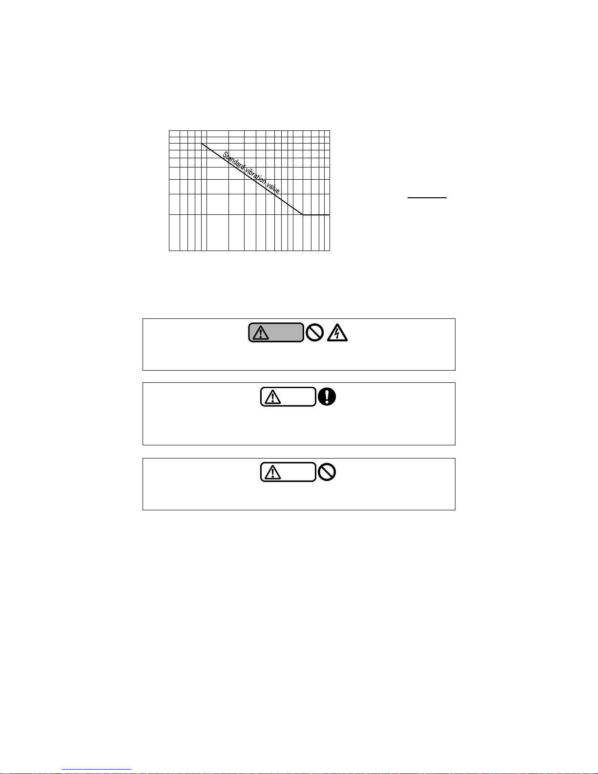
(8) Check for any abnormal pressure, electric current, vibration, noise, and other conditions.
Refer to the following chart for the “vibration vs. rotation speed.” (If you install the pump on a
vibration isolator, the st andard vibration values are different from those in the following chart.
Contact us in such a case.)
Rotation speed (min-1)
Standard vibration value at the bearing section
[For reference only]
Relation between the total amplitude (a)
and the vibration velocity (V)
a =
V×4×10
4
π×n
a: Total amplitude (μm)
V: Vibration velocity (mm/s)
n: Equipment rotation speed (min
-1
)
(9) Stop the pump.
Warning
Do not put your fingers or other objects into the opening of the motor.
Otherwise, it may lead to an electrical shock or injury.
Caution
Keep the cocks of the pressure gauges, compound pressure gages, and
other parts closed all the time except when they are used for
measurement. Otherwise, they become more susceptible to failure.
Caution
Do not run the pump using the power beyond the allowable current value.
Otherwise, the motor may burn out.
100
80
60
40
20
10
600 800 1000
1500 2000 3000 4000 6000 8000
Total amplitude
(1/1000 mm)
Page 26
5-1
5. Maintenance and inspection
Warning
Before checking the pump, be sure to turn off the main power. The pump
may suddenly start up in automatic mode or on other occasions and lead to a
great danger.
Warning
Before starting the unit or carrying out maintenance/inspection work, ensure
that all the relevant workers are informed of the operation and that there are
no workers in the dangerous zone.
Caution
For overhaul, replacement of parts, or repairs, ask the vendor, the servicing
company specified by Teral, or your nearest Teral sales office. Incorrect
work may cause a failure or accident.
5.1 Precautions for maintenance and inspection
(1) Observe the following instructions, in particular, during daily inspection.
A large deviation in the pump's discharge pressure, electric current, vibration, noise, or other
conditions from the normal status is a sign of an imminent failure. Therefore, immediately take
measures, referring to the Maintenance checklist in Section “5.4 Maintenance checklist.”
For this purpose, it is recommended to keep an operation log.
If the bearing temperature gets abnormally high, immediately stop the pump and check the
bearing. The temperature is normal if the temperature difference between the bearing case
surface near the bearing and the atmosphere does not exceed 40°C.
Replace the bearings if they generate unusual noise or vibration.
An oil seal is installed to block the water entry into the bearing section. Replace it at the same
timing to replace the bearing.
If gland packing is used as a shaft seal, check that the gland packing housing does not
generate heat abnormally. If the drip rate is too small, it might generate heat abnormally.
Even after tightening the nut of the packing retainer, the drip rate cannot be adjusted, replace
the gland packing or both the gland packing and the main shaft. Refer to “5.2.1 Gland p acking”
for details.
If mechanical seal is used as a shaft seal, high-frequency sound (mechanical squeak) may be
generated occasionally, but it is not a pump failure. You can continu e to use the pump with th e
same good quality.
Normally, if mechanical seal is used as a shaft seal, liquid leakage hardly occurs. If liquid
leakage becomes frequent, replace the seal. (At the time of initial period of operation, a small
amount of leak may occur, but it is not a pump failure. The leak should stop in several
overheat of operation.) For details, refer to “5.2.2 Mechanical seal.”
Check the piping for any water leakage or damage.
Check that all mounting bolts and the power terminal block are securely connected.
Except when inspection is required, keep the cocks of the pressure gauges and compound
gauge closed all the time with the pressure being released.
○
11
In the event of a power failure, be sure to turn off the power. The pump suddenly starts up on
restoration of the power, and it is dangerous.
Warning
In the event of a power failure, be sure to turn off the power switch. The
pump may suddenly start up on restoration of the power, which leads to a
danger.
Page 27
5-2
○
12
Check the strainer fitted on the pump suction side, for any clogging. Clean it if it is clogged.
Caution
Periodically clean the strainer located on the pump suction side. A clogged
strainer may cause pressure fluctuations, a lower discharge rate, abnormal
noise, and other problems, thus leading to a pump failure.
(2) If you do not use the pump for a long time, observe the following points.
① To prevent possible freezing inside the pump in winter, be sure to take antifreeze measures
such as heat insulation or the installation of a heater to the pump or completely drain the
pump.
② If gland packing is used for shaft sealing, the shaft seal part may be rusty when the pump is
not used for a long period of time. Remove the gland packing, dry away all moisture from the
shaft, apply grease for rust prevention and install a n ew gland packing.
③ If mechani cal seal is used for the shaft, its sliding surface may become sticking in place, thus
making it difficult to rotate the shaft smoothly. Therefore, periodically run the pump to maintain
its smooth rotation. Moreover, before running the pump, turn the pump shaft by hand to check
its smooth rotation.
Warning
Before turning the pump shaft by hand to check its smooth rotatio n, be
sure to turn off the main power. Otherwise, the pump may start
unexpectedly, thus leading to an accident.
④ If you have a backup pump, run it from time to time to make it available for operation at any
time.
5.2 Shaft seal parts
5.2.1
Gland packing
Caution
Be careful not to tighten the gland packing excessively or unevenly.
Otherwise, it may cause excessive heating of the shaft seal part, or
damage to the gland packing and the main shaft.
Nut
Shaft seal part
Main
shaft
Gland packing
Gland packing
retainer
Stud bolt
(1)
Adjust the drip rate from
the gland packing as shown the table below. Do not carry out this
adjustment during the initial period of pump operation. If the gland packing is excessively heated,
or drip rate is too small, loosen the gland nut.
Page 28
5-3
A drop of water that drips out of the gland is
about 0.05cc.
20cc/min: The drip amount of the water of the
degree that falls as droplets or like thread
The drip rate is subject to change according to
the operating conditions.
Pump suction inlet
diamete
r
S
tandard drip rate from the
gland packing (as a guide)
65 mm or less 10 to 20 [cc/min]
80 mm or over 15 to 30 [cc/min]
(2) If the drip rate is not reduced suf
ficiently after 30 minutes of the initial operation, tighten the gland
nut gradually and evenly, while paying attention to heating of the packing.
(3) The drip rate increases gradually over time. When it reaches roughly twice the value in the table,
retighten the gland nut.
(4) Eventually,it will not be possible to tighten the packing retainer any further. When this happens,
replace the packing.
(5) Insert the gland packing rings carefully one by one, as far as it will go. In addition, the rings should
be oriented so that each of their adjacent cut slits will be 90 to 120 degrees apart.
(6) Gland packing is a consumable part. Its life depends on the quality of liquid, having
foreign objects or no, pressure, etc.
5.2.2 Mechanical seal
(1) The mechanical seal is a precision part for preventing water leakage from the clearance of the
pump shaft. Carefully handle the seal to ensure the proper operation of the pump.
(2) The mechanical seal is a consumable. It wears at a different rate depending on the properties of
circulating liquid, the presence of foreign matter, operating pressure, and other factors; and the
service life changes accordingly
(3) If there is any water leakage at the mechanical seal, replace it.
During the initial period of running a new pump, a small amount of leak may occur until the sliding
surfaces on the mechanical seal completely settle (or fit) into place, and the leak should stop in
several hours of operation. Since this initial leak does not mean a defect of the mechanical seal,
you can normally use the pump.
5.3 Bearings
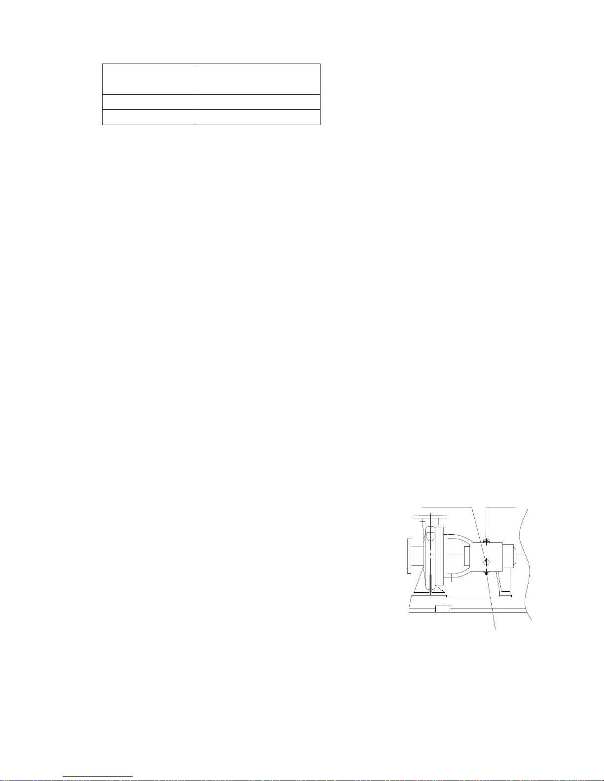
(1) The bearing used for the pump is oil bath type. Pour in oil until the
oil level reaches the center of red-circle of the oil gauge. Do not
run the pump when the oil level goes above the red-circle. If the oil
level is too low, the bearing may be seized up. Also if the oil level
is too high, oil may leak from the bearing.
(2) Use Turbine oil #32.
(3) Oil should be replaced with new oil every 10,000 hours operation.
Oil should be replaced at least every two years even if the pump
has operated for less than 10,000 hours.
Oil gauge Oil feeding plug
Drain
(4) An oil seal is
installed for the purpose of sealing oil. The oil seal is a consumable part. When oil
leakage is increasing and when exchanging a bearing, replace it with a new one. The service life
of oil seal will greatly depend on a surrounding environment and influence of heating liquid
temperature.
(5) Make sure to prevent water from directly entering into the air vent hole in an oil feeding plug.
Page 29
5-4
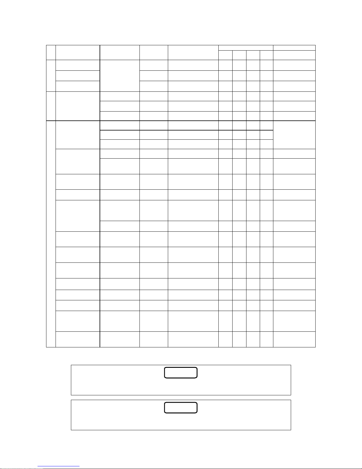
5.4 Maintenance checklist
Inspection interval Consumables
Item
Inspection point Inspection item
Inspection
method
Criterion
(Reference page)
Daily Monthly
Half-
yearly
Yearly
Timing of replacement
(as a guide)*
Temperature Measure
Between 0 and 40°C
(2-2)
-
Humidity Measure
Less than 85% RH (2-2)
(no condensing)
-
Ambient
conditions
Dust and other
contaminants
Check against the
specified range.
Visual check
No dust or other
contaminants
-
Voltage Measure Specified voltage (2-2)
-
Voltage fluctuation Measure
Within the allowable
fluctuation range (2-2)
-
Power
Power terminal block
Loose screws Retighten Securely tightened
-
Performance Visual check As per the specifications
Current value Measure As per the specifications
Operation condition
Noise, vibration Listen, Touch No abnormal vibration
When abnormality is
recognized,
disassemble and
inspect the pump.
Clogging
Disassemble and
inspect
No clogging
Impeller
Wear
Disassemble and
inspect
No abnormal condition
When worn out and
performance is
deteriorated
Liner ring Wear
Disassemble and
inspect
No abnormal condition
When worn out and
performance is
deteriorated
Main shaft and its
surrounding area
Smooth rotation
Rotate by
hand
Rotation is smooth and
uniform
-
Heat-generation,
noise, vibration
Touch,
Listen, Visual
check
No abnormal
condition(5-1)
Every three years
(or after
15000-hours
operation)
Bearing
Oil supply (pump)
Visual check,
Listen
No abnormal vibration or
noise. No leakage
Refer to 5.3 for oil
supply
Oil seal
Leakage
Visual check
No leakage
Every 2-3 years (at
the timing to replace
bearing)
Gland packing
Leakage
Retighten
Proper drip rate (5-2)
Every 6 months (or
after 2000-hours
operation)
Mechanical seal
Leakage
Visual check
No leakage (5-3)
Once a year (or af t er
8000-hours
operation)
Coupling rubber Deterioration, wear Visual check
Abnormal abrasion
No deterioration
Rubber body:
Every 3-5 years
O-ring, packing
-
- -
Whenever
disassembled
Appearance
Unusual noise,
vibration
Visual check,
Listen
No abnormal condition
-
Winding resistance
Resistance value
between each
winding (U-V, V-W,
W-U)
Measure
Resistance value is
uniform between the
windings
-
Pump and motor
Insulation resistance
Between the
ground and each
lead wire
Measure
1 MΩ or more (by
DC500V Megger tester)
-
* The timing of replacing consumables (as a guide) does not mean their guaranteed service life. The service life of parts
varies depending on the ambient conditions and the conditions for use.
Note
The timing of replacement for the consumables is the reference values when normally
used and checked regularly. It may become short according to the use condition.
Note
Dispose of the waste components generated by the repair or the replacement
according to the local regulations, by asking the specialized waste disposal contractor.
Page 30
6-1
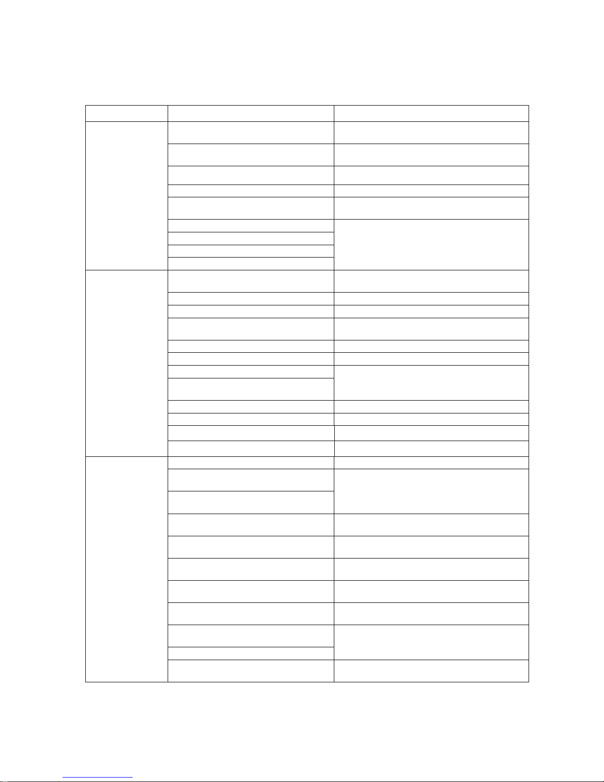
6. Troubleshooting
If you find any abnormal conditions of the pump, carefully investigate the problem. For overhaul,
replacement of the parts or rep airs, ask the vendor or contact Teral or our servicing companies.
Problem Cause (Reference page) Action (Reference page)
Wiring is disconnected or broken.
Check the wires and connections to repair or
replace.
Poor connection or contact of power wires
(3-11)
Check by a tester and replace the defects with a
good one if any.
The power fuse is blown. Replace it with an appropriate fuse.
Tripping of the thermal relay Check the thermal relay.
The power voltage is too low. (2-2)
Check the power voltage and contact the power
company.
The motor has failed.
Foreign matter is caught in the impeller.
The shaft seal is bound.
The pump does not
start.
The bearing is rusty.
Contact Teral or our servicing companies because
disassembly and inspection are required.
The priming in the casing is not enough.
(4-1)
Fully prime the water.
The pumping liquid contains many bubbles. Prevent the formation and suction of bubbles.
The air intrudes from the suction piping. Check the joint of each suction piping.
The rotation direction is reverse. (4-3)
Correct the wiring so that the motor rotates in
normal direction. (4-3)
The piping loss is high. Check the diameter, route and length of the pipes.
The piping is clogged with foreign matter. Check and clean the piping.
The impeller and the liner ring are worn.
Foreign matter is accumulated in the
impeller and in the casing.
Contact Teral or our servicing companies because
disassembly and inspection are required.
The rotation speed is low. Check with the tachometer.
The sluice valve is closed. (4-3) Open the sluice valve.
There is a leak in the discharge pipe. Check and repair the pipe.
The pump starts, but
cannot achieve the
specified discharge
rate and the
specified head.
The total suction head is too high. (3-1) Consult us or our servicing companies.
The rotation speed is too high. Check with the tachometer.
The stator winding is broken, shorted, or
grounded.
The stator and rotor are in contact due to
wear of the bearing.
Contact Teral or our servicing companies becaus e
disassembly and inspection are required.
The motor is running in open-phase
condition.
Check the wiring.
The setting of overload protection device is
too low.
Correctly set the motor overload protection device.
The power supply voltage is out of the
allowable fluctuation range.(2-2)
Check the voltage and contact the power company.
A 50Hz pump is run in the 60Hz power
zone.
Check the nameplate.
The discharge rate is high.
Throttle the sluice valve to adjust the rate as per the
specifications.
A rotating part is in contact with another
part.
Foreign objects enter into the pump.
Contact Teral or our servicing companies becaus e
disassembly and inspection are required.
Overload and
overcurrent of the
motor
The gland packing is excessively tightened.
(5-2)
Properly adjust the drip rate from the gland
packing. (5-2)
Page 31
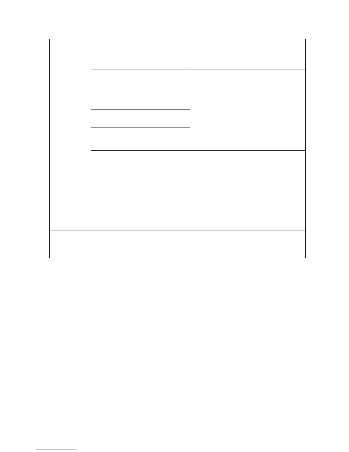
6-2
Problem Cause (Reference page) Action (Reference page)
The bearing is worn or damaged. (5-1)
The oil is leaking.
Contact Teral or our servicing companies because
disassembly and inspection are required.
The oil level is low or the oil is deteriorated. Replenish the oil. (5-3)
Overheat of
bearing
Incorrect installation of the pump and the
piping, misalignment of the shaft (3-1)
Check and correctly install or realign them.
The bearing is worn or damaged. (5-1)
The impeller is clogged with foreign matter,
thus leading to imbalanced load.
The main shaft is winding.
Abnormal noise from the shaft seal
(mechanical seal).(5-1)
Contact Teral or our servicing companies because
disassembly and inspection are required.
The motor is running in open-phase
condition.
Check the wiring.
Cavitation has occurred. (3-10) Consult Teral or our servicing companies.
Incorrect installation of the pump and the
piping, misalignment of the shaft (3-1)
Check and correctly install or realign them.
Unusual noise
and unusual
vibration of the
pump
Inverter is used.(3-12) Change the operating frequency or carrier frequency.
An abnormal
amount of water
is leaking from
the shaft seal.
Damage to the mechanical seal (5-1)
If the leakage becomes large, replace the seal. (5-1)
Contact Teral or our servicing companies because
disassembly and inspection are required.
Foot valve or check valve is damaged. Inspect and replace the foot valve and check valve.
When the power
is turned off, the
pump rotates
backward.
The suction pipe leaks the liquid. Inspect and repair the pipes.
Page 32
TP-346-01
Head Office
230, Moriwake, Miyuyki-cho, Fukuyama-city, Hiroshima, 720-0003, Japan
Tel.084-955-1111 Fax.084-955-5777
Overseas Div.
TERAL Koraku Bldg., 2-3-27, Koraku, Bunkyo-ku, Tokyo, 112-0004, Japan
Tel.03-3819-6890 Fax.03-3818-6790
TP-472-00
 Loading...