

Page 1
Model : LHW-e/LPW-e/LPW-7W/ LKW-e
LFE/LFE-e
Coolant Pump
Coolant Pump
Instruction Manual
Page 2

I
Limited warranties
1. In the event of a failure or breakage under proper use of the product during the warranty period,
equipment supplied by Teral Inc. shall be repaired or replaced free of charge within the scope of the
relevant part, provided that such failure or breakage is attributable to inadequacy of the design or
workmanship of the equipment.
The warranty period of this product shall be one year after the date of delivery.
2. The warranty mentioned in the above clause shall be only the mechanical warranty of the defective part,
and shall not cover any expenses or other damage arising from the failure or breakage.
3. In the event of the following failures and breakage, the costs of the repairs shall be borne by the user.
(1) Failures and breakage attributable to equipment that was not delivered by Teral Inc.
(2) Failures a nd breakage after the expiration of the warranty period
(3) Failures a nd breakage caused by disasters or force majeure, such as fire, acts of God, or
earthquakes
(4) Failures and breakage resulting from repairs or modifications made without the consent of Teral
Inc.
(5) Failures and breakage when parts other than those d esignated by Teral Inc. are used
(6) Failures and breakage caused by use or storage outside the specification range
4. Teral Inc. shall not be liable for the damage caused by incorrect or reckless use of the pump. Cost and
expenses incurred for sending engineer(s) in such a case shall be borne by the use r.
5. If the cause of the failure is unclear, necessary actions sh all be determined through mutual
consultation.
<Chargeable repair>
Investigation and repair work after the warranty period shall become chargeable. For any failures that have
occurred within the warranty period but that fall outside the above-mentioned warranty coverage, Teral Inc.
shall carry out repairs and investigation for a fee.
Page 3

II
Purpose of this manual
The purpose of this manual is to provide the user with detailed information necessary to properly operate,
maintain and inspect the pump. Incorrect operation of this product may lead to an unexpected acci dent.
Please use the product correctly according to this instruction manual.
This manual contains the following information and is intended for persons experienced in the operation of
pumps, or for those who have been trained by such experienced operators. Only qualified personnel such
as licensed electrical engineers are allowed to carry out the electrical wiring work.
Contents
(Page)
Limited warranties .................................................................................................................................... I
Purpose of this manual........................................................................................................................... II
Contents.................................................................................................................................................... II
1. Safety precautions............................................................................................................................... 1-1
1.1 Types and meanings of safety signs and graphic symbols.........................................................1-1
1.2 Safety precautions....................................................................................................................... 1-1
1.3 Location of warning labels and caution labels.............................................................................1-4
2. Configuration and overview of the pump.............................................................................................2-1
2.1 Part names and functions............................................................................................................2-1
2.2 Standard specifications...............................................................................................................2-2
3. Installation ........................................................................................................................................... 3-1
3.1 Before using the pump ................................................................................................................3-1
3.2 Precautions for installation..........................................................................................................3-1
3.3 Precautions for piping work.........................................................................................................3-4
3.4 Precautions for wiring work.........................................................................................................3-5
4. Operation............................................................................................................................................. 4-1
4.1 Check items before test operation...............................................................................................4-1
4.1.1 Check items related to the electrical system.......................................................................4-1
4.1.2 Check items related to the pump.........................................................................................4-1
4.2 Running the pump (test operation).............................................................................................. 4-2
5. Maintenance and inspection................................................................................................................5-1
5.1 Precautions for maintenance and inspection..............................................................................5-1
5.2 Replacement of the V-ring (for LPW65-e)...................................................................................5-2
5.3 Maintenance checklist.................................................................................................................5-4
6. Troubleshooting................................................................................................................................... 6-1
Page 4
1-1
1. Safety precautions
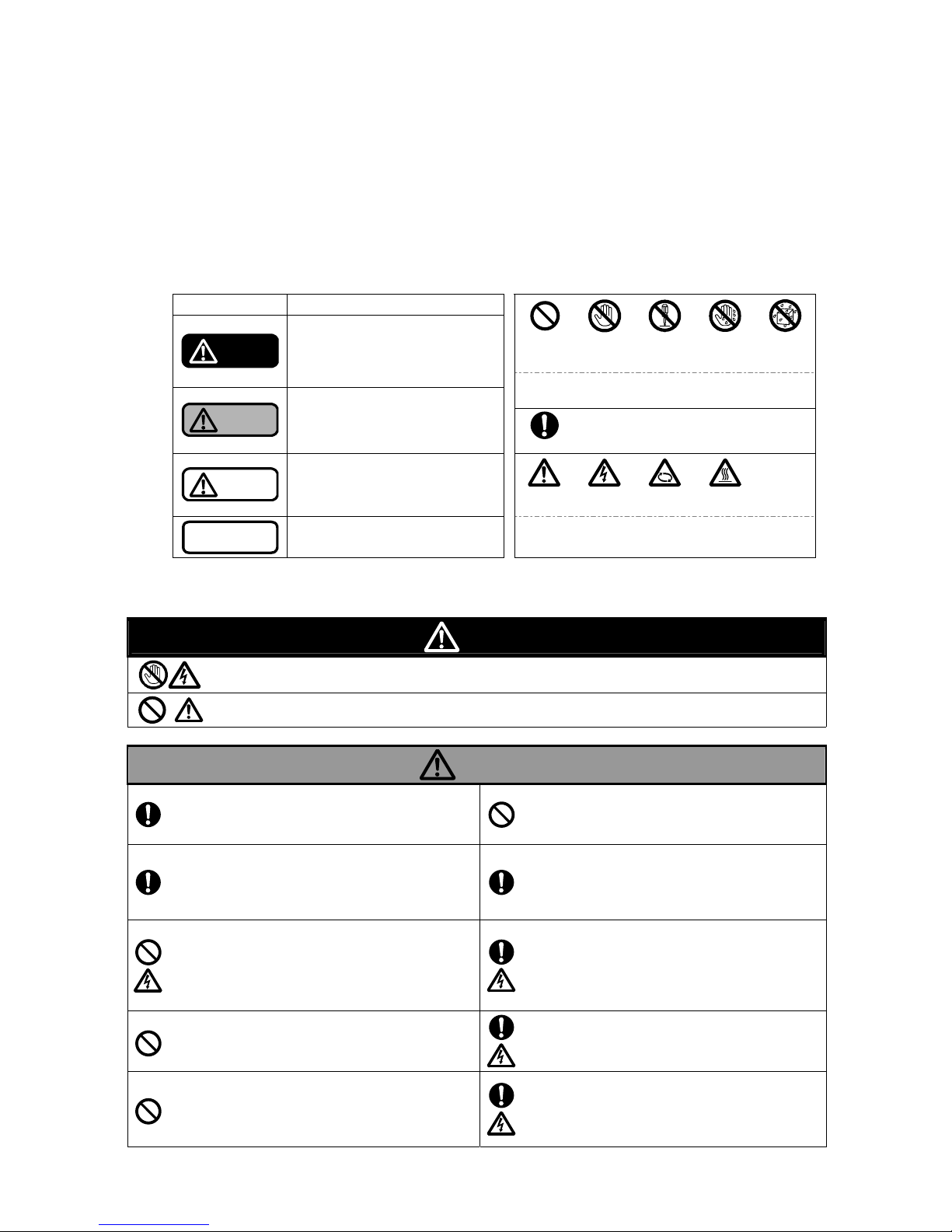
1.1 Types and meanings of safety signs and graphic symbols
This instruction manual divides precautions into the following four categories according to the level
of hazards (or the severity of the accident). In addition, prohibited or mandatory actions as well as
cautions are indicated with a graphic symbol.
Be sure to understand the meanings of the following terms and comply with the content
(instructions) of the instruction manual.
Explanation of warnings Explanation of the graphic symbols
Safety sign Meaning
Don’ts Do not touch Do not
disassemble
Do not touch
with wet
hand
Do not
expose to
water
Danger
Indicates an imminently hazardous
situation. Failure to observe this will
result in death or serious injury.
These graphic symbols indicate prohibited actions (that
must NOT be done).
Warning
Indicates a potentially hazardous
situation. Failure to observe this will
result in death or serious injury.
Do’s
This graphic symbol indicates mandatory
actions (that must be done).
Caution
Indicates a potentially hazardous
situation. Failure to observe this will
result in minor or moderate injury or
property damage.
Caution Electric
shock hazard
Rotation
hazard
Hot surface
Note
Indicates information that is in
particular to be noted or emphasized.
These graphic symbols indicate existing hazards to
beware of.
1.2 Safety precautions
Danger
Once the main power is turned on, do not touch any live parts.
A high voltage applied to live parts may cause a serious electric shock, thus leading to death.
Do not use the product in any explosive atmosphere.
Otherwise, it may lead to an injury or fire.
Warning
Properly move the unit according to lifting
instructions.
Otherwise, the unit may fall, thus leading to an injury or
damage.
Do not carry out any work with/on the pump that is
being lifted.
Otherwise, the unit may fall, thus leading to an injury or
damage.
Only those who are authorized by the site manager
are allowed to operate the pump.
Operation by unskilled personnel may lead to an unforeseen
accident.
Installation, maintenance, and inspection must
only be carried out by personnel who have been
trained to handle the pump.
Operation by unskilled personnel may lead to an unforeseen
accident.
Only qualified personnel, such as licensed electrical
engineers, are allowed to carry out electric work.
Otherwise, it may lead to an electric shock, fire, failu re, or
other problems.
Use high-quality wiring equipment and devices,
and carry out wiring work safely and securely
according to the technical standards for electrical
facilities, as well as the indoor wiring regulations.
Otherwise, it may lead to an electric shock, fire, or other
problems.
Do not connect the ground wire to a gas pipe or
water pipe.
Such a connection is illegal and leads to an electri c shoc k,
explosion, or fire.
Securely install the ground wire and ensure to
carry out grounding work.
Otherwise, it may lead to an electric leak or electric shock.
Do not run the unit if abnormal condition is observed
in any operation, movement, parts, etc.
Otherwise, it may lead to an injury, failure, or various
accidents.
Correctly and securely connect the wires
according to the wiring diagram within the terminal
box and the instruction manual.
Incorrect wiring may cause a fire, electric shock, failure, or
other problems.
Page 5
1-2
Warning
Be sure to keep the terminal box cover attached
during the operation of the pump.
Otherwise, it may lead to an electric shock.
Be sure to install the coupling cover during the
operation of the pump.
Otherwise, it may lead to an injury or damage.
After detaching the companion flange from the
pump, screw a pipe into it.
Otherwise, it may lead to damage or leakage.
Do not forcibly bend, pull, or pinch the power cable
or any lead wires of the product.
Otherwise, it may lead to an electric shock or fire.
Check the wiring sections and wires for any
looseness.
A loose connection may cause a fire or electric shock.
Before starting the maintenance or inspection
work, be sure to stop the pump and turn off the
main power of the panel board.
Otherwise, it may lead to an electric shock, injury, damage,
or leakage.
Before starting the unit or carrying out
maintenance/inspection work, ensure that all the
relevant workers are informed of the operation and
that there are no workers in the dangerous zone.
Otherwise, it may lead to an unforeseen accident.
Before rotating the main shaft by hand to check its
smooth rotation, be sure to turn off the main power.
Otherwise, it may lead to an injury or damage.
After turning on the power, do not touch any parts of
the pump other than those required for operation.
Otherwise, it may lead to an electric shock or injury.
Do not perform long hours of zero-discharge
operation continuously.
Otherwise, the temperature and pressure may increase
inside the pump, thus damaging the pump or causing steam
to blow off.
Do not put your fingers or foreign objects into any
openings or rotating part of the motor during
operation.
Otherwise, it may lead to an injury or damage.
For overhaul, replacement of parts, or repairs, ask
the vendor or the service center specified by Teral.
If unskilled personnel carry out work that requires special
knowledge, it may lead to an accident or failure.
In the event of a power failure, be sure to turn off the
power switch.
Otherwise, the pump may suddenl y start up on restoration of
the power, thus leading to an injury.
Caution
Do not use the unit outside the range of the product
specifications.
Otherwise, it may lead to an electric shock, fire, leakage,
failure, or other problems.
Do not use the unit at an incorrect power voltage.
An incorrect voltage may damage the motor.
Do not use a single pump unit as the only means of
directly operating key facilities or sustaining life.
In the event of a failure, the water supply may stop. Ensure to
make a backup unit available for operation.
Before unpacking the delivered container, check
that the container is placed in the correct
orientation (not upside down). Carefully unpack the
container, while paying special attention to nails.
Otherwise, it may lead to an injury or damage.
Ensure that the floor at the unit’s installation place is
waterproofed and fitted with drainage.
Otherwise, it may lead to serious damage in the event of
leakage.
Do not install two or more different cables or
control wires in one pipe or duct.
Otherwise, it may lead to ma lfunction o f the product or other
equipment.
Do not step on the pump or motor.
Otherwise, it may lead to an injury, damage, or other problems.
Do not expose the motor to water.
Otherwise, it may lead to an electric shock, electric leak,
failure, or other problems.
Operate the controls carefully.
Otherwise, it may lead to an injury or damage.
Never run the pump dry.
Otherwise, it may lead to damage or a fire.
Before operation, thoroughly clean (flush) the inside
of the piping to remove foreign matter.
Otherwise, the piping system may be contaminated with
foreign matter, thus leading to an accident or a pump failure.
Page 6
1-3
Caution
Do not put a cloth or other covering on the motor.
Otherwise, it may lead to overheating or ignition.
Do not touch the motor body while the pump is
running or immediately after the pump has stopped.
Otherwise, you may get burns from the hot surface.
In the event of an alarm or abnormal condition that
cannot be resolved, immediately stop the
operation, turn off the power, and then contact Teral
or its service provider.
Otherwise, it may lead to an accident.
Do not run the pump with tools or other objects
placed on the unit.
Otherwise, it may lead to an injury or damage.
Check that the delivered items are exactly what you
ordered.
The use of a wrong product may cause an injury or failure.
Do not hold the strainer located on the tip of the
pump.
Otherwise, the strainer may come of f, th us leadi ng to an injury
or damage.
Do not place any obstacles around the product that
may hinder ventilation.
Otherwise, it may lead to a fire.
Do not place any combustibles around the product.
Otherwise, it may lead to a fire.
Do not run the pump at a frequency exceeding 60
Hz (50 Hz for models dedicated to 50Hz).
Otherwise, it may lead to motor burnout or a fire.
Do not touch the impeller, tie bolt, strainer, or other
parts of the pump with bare hands.
Otherwise, it may lead to an injury or damage.
Ensure to install an overcurrent protective device.
The user is required by the technical standards for electrical
facilities to install one. Otherwise, it may damage the product,
thus leading to a fire or failure. It is also recommended to
install protective devices such as a groun d fau l t interrupter.
Do not use the unit for pumping any fluids beyond
the specified viscosity limit.
Otherwise, it may lead to motor burnout or a fire.
Do not run the pump with its strainer removed.
Otherwise, it may lead to an injury or damage.
Do not touch any terminals or wires when
measuring the insulation resistance.
Otherwise, it may lead to an electric shock.
Do not touch the Impeller after removing the
strainer.
Otherwise, it may lead to an injury.
Once you turn off the power, wait until the pump
stops completely. Do not restart the pump until it
does.
Otherwise, the main shaft may be subjected to an excessive
load, which makes the service life of the pump shorter.
Do not use thinner or benzine for cleaning the
product.
Otherwise, the product may be discolored or its coating may
be peeled off.
If you use a solvent for cleaning the product, pay
attention to handling of the solvent as well as the
environment of use.
Otherwise, it may lead to poisoning.
When you lift the product, pay attention to its center
of gravity.
Otherwise, the product may topple over or fall, thus leading to
an injury.
Dispose of the product as industrial waste.
Be sure to conduct inspection according to the
Maintenance checklist.
Otherwise, you cannot prevent potential failures, thus leading
to a higher risk of accidents.
When you lift the product by hand, pay attention to
its weight. Do not allow a single person to lift a
product heavier than 15 kg.
Otherwise, it may put strain on the body, thus leading to an
injury.
Do not put your fingers or foreign objects into the
immersion detecting hole.
Failure to observe this may lead to an injury or
damage.
Page 7
1-4
Motor name plate
1.3 Location of warning labels and caution labels
The figure shows the locations of warning labels and caution labels. If these labels become dirty and
illegible or if they are peeled off, replace them with a new one.
Warning
Caution
Observe all the warnings and cautions affixed to
the machine as well as those described in this
instruction manual.
Page 8
2-1
2. Configuration and overview of the pump
This chapter describes the standard specifications of the pump. If you have purchased a customized
product, some information in this chapter may not be applicable to your unit. Refer to the delivery
specifications for the details separately.
Caution
Do not use this product under any conditions other than those
provided in the specifications. Otherwise, it may lead to an electric
shock, fire, leakage, or failure.
2.1 Part names and functions
Motor
Discharge port
Suction port (with strainer)
Air vent valve
If air cannot be released from the pump to the
atmosphere on the discharge piping, you can
discharge air using this valve to prevent dry
running.
Immersion detecting hole (LHW-e, LKW-e,
LPW40/50-e,LPW40/50-7W)
If liquid leakage occurred from the immersion
detecting hole, check the shaft sealing part.
Coupling (LPW65-e)
Coupling cover (LPW65-e)
Warning
Caution
Be sure to keep the coupling cover and the strainer attached du ring
the operation of the pump. Failure to observe this may lead to an
injury.
Caution
Do not put your fingers or foreign objects into the immersion
detecting hole. Failure to observe this may lead to an injury or
damage.
※
The appearance is different according to the model.
Representing model
(The drawing shows LPW40-e)
LPW65-e
Page 9
2-2
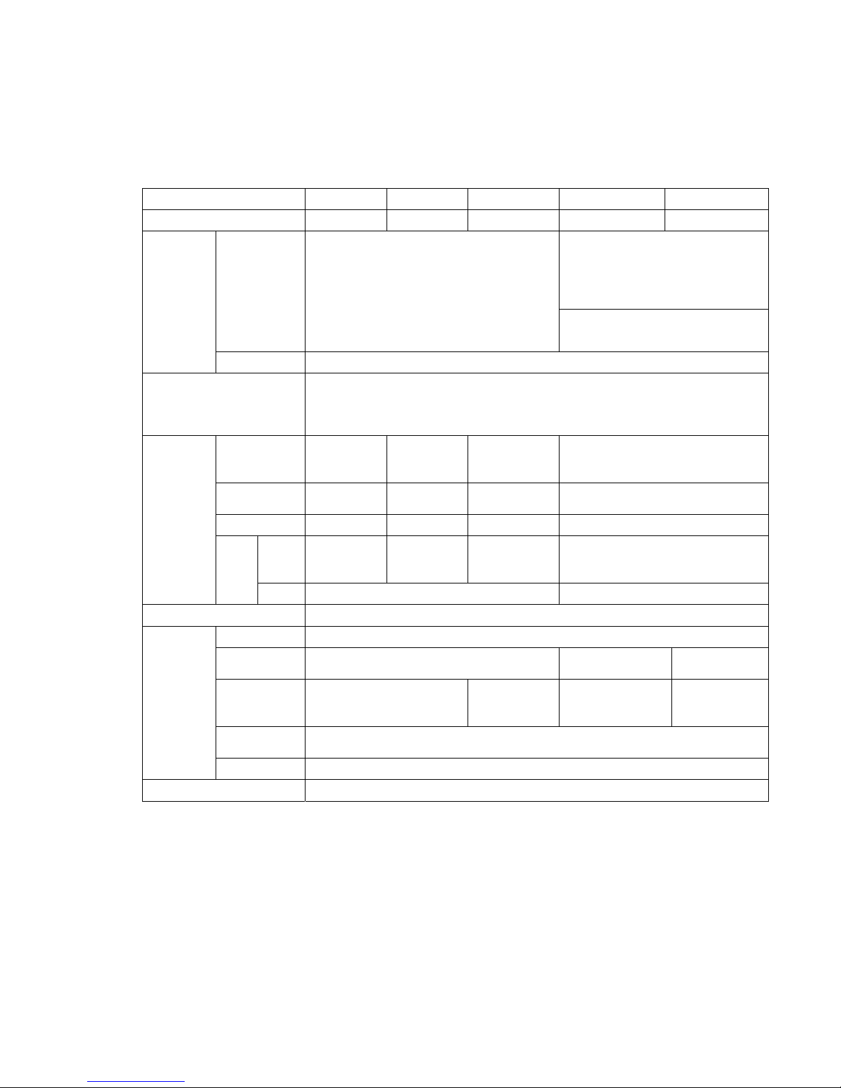
2.2 Standard specifications
If you have purchased our standard product, refer to the “Standard specifications” table. If you have also
purchased a customized product with special specifications, refer to the delivery specifications.
・Standa rd specification s
Model
※1
LHW-e LKW-e LFE/LFE-e LPW-e LPW-7W
Nominal diameter(mm) 20 20 32/50/65 40/50/65 40/50
LPW40:W ater-soluble coolant, liquids
of similar viscosity to water containing
additives (anti-rust agents) and the
like (up to 32 mm
2
/s for LPW40C, up
to 150 mm
2
/s for LPW40D※2)
Quality
Water-soluble coolant
(dynamic viscosity 1mm
2
/s)
LPW50/65:Water-soluble coolant
Applicable
liquid
Temperature 0 to 60 °C (No frozen liquid is allowed.)
Installation location
Indoors; height above sea level: 1,000 m or less; ambient temperature: 0 to
40°C; humidity: less than RH85% (no condensing); place not exposed to direct
sunlight; place without any corrosive gas, explosive gas, or vapor in the
atmosphere
Suction casing
(Suction cover)
Discharge casing
FC200 FC200 FC200 FC200
Intermediate
casing
ARLS
ARLS
+(SUS304)
- FC200
Impeller ARLS ARLS FCD450 FCD450
Motor
Equivalent
to
SUS420J2
S35C S35C LPW40/50:S45C
Material
Main
shaft
Pump -
LPW65:S45C
Shaft sealing structure
Sealless structure(without mechanical seal)
Type Totally-enclosed fan-cooled indoor type
IP protection IP44
LPW40/50:IP44
LPW65:IP55
IP54
Power※3
3-phase
50/60Hz
200/200-220V
3-phase
60Hz
200-220V
3-phase
50/60Hz
200/200-220V
3-phase
60Hz
208-230/460V
Insulation
class
Class F
Motor
Number of poles
2P
Coating color Munsell N1.5
* 1 All the models that the suffix “-e” is appended to the model name are the products with a built-in
premium efficiency (IE3-equivalent) motor. All the models that the suffix “-7W” is appended to the
model name are the products with a built-in UL standard motor.
* 2 Note that the product can be used for the water containing additives (anti-rust agents) such as
water-soluble or non water-soluble coolant, but cannot be used for water.
* 3 Limit the fluctuations of the power voltage within ±10% of the rated voltage, and also limit the
fluctuations of the frequency between –5% and +3% of the rated value. Avoid continuous
operation if the voltage is not within ±5% of the rated value or if the frequency is not within ±2% of
the rated value.
*
Page 10
3-1
3. Installation
3.1 Before using the pump
Upon receiving the pump, check the following points first.
The container may greatly incline depending on its center of gravity.
Caution
Before unpacking the delivered container, ensure that the container is
placed in the correct orientation (not upside down). Pay special attention to
nails especially when opening a wooden crate. Otherwise, you may get
injured.
(1) Check the nameplate to verify that the delivered product is exactly what you ordered.
(2) No part of the product is damaged during transportation.
(3) All fastening parts including bolts and nuts are securely tightened.
(4) All the accessories that you ordered have been delivered. (Note that the direct operation type
contains the pump and the accessories such as bed in separate packages.)
Warning
Do not hold the strainer on tip of the pump during handling. Failure to
observe this may cause the strainer to come off, resulting in an injury or
damage.
Caution
When lifting the product by hand, pay attention to its center of gravity and
weight. Do not allow a single person to lift a product heavier than 15 kg.
Failure to observe this may cause the burden on the body, resulting in an
injury.
Caution
Do not run the pump at a frequency exceeding 60 Hz (50 Hz for models
dedicated to 50Hz). Failure to observe this may cause an overload and
burnout of the motor.
3.2 Precautions for installation
(1) Install the product in a well-ventilated place with minimum exposure to dust and moisture. In
particular , avoid inst alling t he product in a place where the pumpin g liquid may be splashed o n the
motor section.
Warning
Do not install the product in a place exposed to high temperature and
moisture.
Failure to observe this may cause heating, ignition or electric leakage.
(2) Install the product so that the motor can take air in.
(3) Securely install the product on a flat place without any wobbles.
Page 11
3-2
(4) Select a convenient place to conduct maintenance and inspection. Secure space for
maintenance.
(5) It is necessary to make a mounting hole larger than the outside diameter of the pump section so
that the pump section can fit into the tank (oil tank). See the dimensional outline drawing.
(6) Install the pump so that the main shaft becomes vertical.
(7) Use the product with the pump section immersed under the oil level. The suction port should be at
least t mm away from the bottom surface of the tank (oil tank) to prevent the strainer from getting
clogged with cutting powder , dirt, or other materials. If cutting powder, dirt, or other materials are
predicted to accumulate on the bottom of the tank, ensure as large a distance as possible from the
bottom at the design stage.
Model h t
LHW-e 45 5
LPW40-e(-7W) 65 25
LPW50Z-e 51 25
LPW50ZL-e(-7W) 36 20
LPW65-e 100 50
LKW-e 45 5
LFE32/LFE32-e 60 20
LFE50/LFE50-e 75 20
LFE65-e 100 20
(8) For model LKW-D-e, refer to the drawing below
and assemble the pump main body and
accessories such as bed.
Note
Always keep the liquid level in the tank (oil
tank) above the Minimum liquid level.
Keep the suction port of the pump at least t
mm away from the bottom of the tank (oil
tank), and at least 5 mm away for LKW-D-e
(series operation).
All
models
In case that pipes and a strainer
are installed (except for LHW-e)
LKW-D-e
Discharge
Bed
Bush 11/4x3/4B
Street elbow 3/4B
Flexible hose 20Ax500L
Tank
bottom
Min. liquid
level
Suction
No.1
pump
No.2
pump
At least
5mm
Page 12
3-3
(9) Install the product at a place where a secondary hazard does not occur in the event of any liquid
leak.
(10) If the system could be exposed to the freezing temperature in winter, be sure to apply antifreeze
measures such as heat insulation and heater installation to the pump, valves, piping, etc.
(11) Securely install the pump.
Note
Securely fix the pump in place with the bolts. Otherwise, it may lead to
abnormal vibration or other problems.
(12) To lif t the pump, pa ss a rope or th e like through the h anging hole of a casing for the model LHW -e,
LPW40/50-e, LPW40/50-7W and pass a rope or the like through the eyebolt of motor for LPW65-e,
LKW-e, LFE/LFE-e. Do not lift he equipment with the pump attached. Failure to observe this may
cause the equipment to break and fall down.
(13) Use extreme care so as not to give an impact or offset load to the pump section during pump
lifting or conveyance. The pump may greatly tilt depending on its center of gravity.
Warning
Before lifting the pump, refer to the catalog, dimensional outline drawing,
and other documents to check the weight of the units. Do not lift any unit s if
its weight exceeds the rated load of the hoisting equipment/devices.
Caution
When lifting the pump by hand, pay attention to its center of gravity and
weight. Do not allow a single person to lift a product heavier than 15kg.
Otherwise, the pump may topple over or fall, thus leading to an injury.
(14) If the pumping liquid is cold, condensation may occur inside the motor while the pump is stopped.
Take measures to prevent condensation, for example, by installing the pump in a sufficiently dry
room or by heating and insulating the motor even when the pump is stopped.
(15) Carry out touchup painting at a time interval suitable for the environment of use. Depending on the
humidity, condensation, and other conditions, rust may form on areas such as threaded parts,
worked areas, anticorrosive-coated sections.
(16) Do not put a cover or filter over the motor. Otherwise, the temperature may increase inside the
motor, thus leading to product damage, fire, or other problems.
Page 13
3-4
3.3 Precautions for piping work
(1) The pipes must be as short and straight as possible with minimal joints and valves. Use pipes
whose bore size is equal to or larger than the discharge port of the pump. If the piping size is small
or there are many bends, the discharge rate may become low.
(2) Ensure to provide adequate pipe supports so that the weight of the piping system will not be
applied directly to the pump body.
Caution
Do not allow the weight of the pipes to rest on the pump.
Failure to observe this may cause the main shaft from coming off center,
resulting in equipment damage, vibration, and noise.
(3) Do not forcibly screw a pipe into the pump. Otherwise, it may break the joint.
(4) Securely connect the pipes so that the connections are kept completely airtight without leakage.
Prevent leaks of liquid and air with seal tape, liquid packing, or other means. Firmly wind the seal
tape while paying attention not to block the piping.
(5) Use a tank (oil tank) with as large a capacity as possible.
* It is recommended to use a capacity of at least three times the discharge volume per minute.
Too small a capacity may cause problems such as the rise of liquid temperature, premature
strainer clogging with cutting powder, and lower discharge rate caused by bubbles.
When pouring a pumping liquid into a tank (oil tank), gently pour it so as not to trap air in.
(6) Do not allow a large amount of cutting powder, dirt, or other contaminants from entering the pump
section. Failure to observe this may clog the pump strainer, damage the pump, or significantly
deteriorate the performance. Before using the coolant pumps, implement the treatment of liquid
through a net cage, a chip conveyor, a magnetic separator, etc as per the table below.
Pumps that can be used after primary treatment LPW-e,LPW-7W
Pumps that can be used after secondary treatment All models
(7) If water hammer may occur, attach a pressure damper (e.g. accumulator).
(8) The pump is packaged with a companion flange for the discharge port. Use it as needed. When
using the flange, be sure to install the supplied O-ring.
(9) If there is an upward curve on the discharge pipe, ensure that air can be vented from the section.
(10) If you provide a relief pipe on the discharge side of the pump, also provide a sluice valve in the
middle of the relief pipe to adjust the relief volume.
Note
If the amount of liquid released from the relief pipe is too much, the liquid
temperature easily rises in the tank (oil tank).
(11) On completion of the piping work, be sure to clean the tank (oil tank) to prevent the suction of
foreign matter.
Page 14
3-5
3.4 Precautions for wiring work
Danger
Use high-quality wiring equipment and devices, and carry out wiring work
safely and securely according to the technical standards for electrical
facilities, as well as the indoor wiring regulations.
Only qualified personnel such as licensed electrical engineers are allowed
to carry out electrical wiring work. Unqualified persons are prohibited by
law to carry out wiring work, and it is very dangerous.
Danger
Securely connect the terminals of the power cable. Loose terminals may
cause the motor to run in open-phase condition, thus leading to motor
burnout.
(1) Be sure to install a ground fault interrupter and an overload protection device on the primary
power side of the pump.
* The starting current of Top Runner efficiency (equivalent to IE3) motor and UL standard
motor-equipped products tends to become higher than that of standard efficiency (IE1)
motor-equipped products. Therefore, when switching from an IE1 motor-equipped produ ct, it is
necessary to verify the applicability of its ground fault interrupter and overload protection device. If
you have any questions, contact your nearest office of Teral.
Note
When switching from an IE1 motor-equipped product, it is necessary to
verify the applicability of its protection device on the primary side of the
pump.
Failure to observe this may cause the protective device to trip on startup.
(2) When connecting to terminals, securely connect to the power according to the below figure.
Page 15
3-6
(3) Be sure to attach a ground wire to prevent an electric shock.
Connect the ground wire to the ground terminal inside the terminal box of the motor.
Warning
Connecting a ground wire to gas or water pipes is illegal and extremely
dangerous.
(4) To prevent the terminal block and power cable of the motor from being pulled, fasten the power
cable to the terminal box with the cable lock.
Warning
Do not change the orientation of the terminal box.
Failure to observe this may cause the liquid to entering the terminal box,
thus leading to an electric shock.
(5) To prevent overload and burnout of the motor, it is recommended to use a thermal relay for motor
protection.
(6) Carry out adequate dust-proofing and drip-proofing using a connector or gland so that cutting
powder and liquid coolant do not enter the terminal box through the external wiring hole.
(7) Pass the power cable through a metal tube or a metal conduit for shielding, and connect a ground
wire to the outer surface of the tube.
(8) Limit the fluctuations of the supply voltage within ±10% of the rated voltage, and also limit the
fluctuations of the frequency between –5% and +3% of the rated value. Although you can run the
pump in these ranges, avoid continuous operation if the voltage is not within ±5% of the rated
value or if the frequency is not within ±2% of the rated value. Otherwise, it may overload the pump,
thus leading to motor damage or a fire.
Even if the power fluctuations fall within the allowable ranges, the pump characteristics, motor
characteristics, and the temperature rise of the motor may differ from those at the rated voltage
and frequency.
(9) For direct operation type, set the circuit so that the pumps starts from No.1 then No.2 (or together)
and stops from No.2 then No.1 (or together).
Page 16
3-7
Warning
Never start the operation with No. 2 pump nor operate No.2 pump only; it
will cause idle operation, leading to the product damage.
(10) Precautions for using the inverter drive
• Ensure that the electric current during operation does not exceed 90% of the rated value.
• Ensure that the minimum frequency is set to 20Hz.
(Contact us if you need to run the drive at 20Hz or lower.)
• When driving a 400V-class motor, contact Teral. In some cases it might be necessary to take
measures for inverter surge.
• An inverter-driven motor generates a magnetic sound which may be annoying compared with
the drives using commercial power supply. Although this magnetic sound does not cause an
adverse effect on the quality of the motor , some invert ers allow the user to adjust the tone by
changing the carrier frequency. However, changing the frequency may reduce the allowable
output of the inverter. Pay particular attention when selectin g the inverter.
• If the pump and motor produce resonance during normal operation, do not run them in the
range of the rotation speed.
Caution
Do not run the pump at a frequency exceeding 60 Hz (50 Hz for models
dedicated to 50Hz). Failure to observe this may overload the motor,
causing it to burnout. If the models dedicated to 60Hz are run at 50Hz, the
performance will deteriorate.
(11) For LPW65-e, be sure to connect the terminals of power cables in a reversed-phase (by
exchanging R with T of the power cables). If the terminals are connected in a positive phase, the
pump rotates in the reverse direction, which may cause damage. For the other models, connect
the terminals of power cables in a positive phase.
Caution
For LPW65-e, be sure to connect the terminals of power cables in a
reversed-phase (by exchanging R with T of the power cables). If the
terminals are connected in a positive phase, the pump rotates in the
reverse direction, which may cause damage.
Page 17
4-1
4. Operation
4.1 Check items before test operation
4.1.1
Check items related to the electrical system
(1) Check that the equipment is correctly wired.
(2) Check that the terminals are securely connected.
(3) Check that the equipment is securely grounded.
(4) Check that the setup value of the overload protection device is consistent with the rated current
value of the motor.
(The rated current of pump should be included in the setting range of the device around the
middle.)
Warning
Do not use the product at any voltage other than the rated value.
Excessive voltage may cause a fire or electric shock.
4.1.2 Check items related to the pump
Caution
Do not allow a large amount of foreign matter from entering the pump.
Failure to observe this may cause damage to the sliding parts (e.g.
bearings) inside the pump, leakage or unusual noise.
(1) Ensure that the liquid level in the tank (oil tank) is above the “Minimum liquid level.”
Caution
Never run the pump dry (running the pump when the liquid level
is below the Minimum liquid level). Failure to observe this cause
the sliding parts inside the pump to seize up.
(2) Check the rotation direction. Normal rotation is clockwise when viewed from the
motor side. (See the right figure.)
(3) To rotate the shaft by hand, insert a flat-blade screwdriver through the fan cover of
the motor and turn its shaft (Remove the end cap from the motor shaft). If the
rotation is stiff or not uniform, there may be some rust or foreign matter inside the
pump. Inspect the pump in such a case.
(4) After rotating the shaft by hand, install the end cap again.
Warning
Before rotating the main shaft by hand to check it, be sure to turn off the
main power. An unexpected start of the pump may cause an accident.
(5) Open the air vent valve to release air. After the air release, close the air vent valve. If no air vent
valve is provided, open the valve on the discharge piping to release air.
Rotation direction
Page 18
4-2
(6) If you run the motor at variable speed with the inverter, be sure to check the following points
through test operations.
· The pump may produce resonance depending on installation conditions. If the pump
produces resonance, avoid that frequency.
· If the operation frequency is low or the dynamic viscosity of the pumping liquid is high, the
pump may not discharge any liquid.
· Do not run the pump at a frequency exceeding 60 Hz (50 Hz for models dedicated to 50Hz).
Failure to observe this may cause burnout of the motor .
Caution
Do not run the pump at a frequency exceeding 60 Hz (50 Hz for models
dedicated to 50Hz). Failure to observe this may cause an overload and
burnout of the motor. If the models dedi cated to 60Hz are run at 50Hz, the
performance will deteriorate.
4.2 Running the pump (test operation)
Warning
Be sure to attach the cover of the terminal box of the motor.
Failure to observe this may cause an electric shock.
Warning
Be sure to keep the coupling cover and the strainer attached du ring the
operation of the pump. Failure to observe this may cause an injury.
Warning
Do not operate the pump if any abnormal condition is observed or if there
is anything wrong with the parts, components, etc. during the check before
test operation. Failure to observe this may cause an injury, failure,
accident, or other problems.
Warning
If the liquid used exceeds 40°C, do not touch the pump.
Failure to observe this may cause burn on the skin due to high temperature
of the pump.
Warning
Do not touch the motor during operation or immediately after the stop of
operation.
Failure to observe this may cause burn on the skin due to high temperature
of the pump.
Page 19
4-3
(1) Check the rotation direction of the pump by turning ON and OFF the power switch once or twice.
For LKW-D-e (series operation), turn ON in the orde r of No.1 pump and No.2 pump or both pum ps
simultaneously, and turn OFF in the order of No.2 and No.1 or both simultaneously. Normal
rotation is clockwise when viewed from the motor side. (For LPW65-e, be sure to connect the
terminals of power cables in a reversed-phase (by exchanging R with T of the power cables). If
the terminals are connected in a positive phase, the pump rotates in the reverse direction, which
may cause damage.)
If the pump rotates in reverse, swap two of the three wires of the power cables.
Caution
Do not check the rotation direction by running the pump dry. Running the
pump dry even for a short time may cause damage to the sliding parts (e.g.
bearings) in the pump, leakage or unusual noise.
Caution
Avoid reverse rotation because it may cause a failure.
For the model LPW65-e, be sure to connect the terminals of power cables
in a reversed-phase to prevent the reverse rotation.
Caution
Do not run the pump dry, and do not allow a large amount of air or foreign
matter from entering the pump. Failure to observe this may cause damage
to the sliding parts (e.g. bearings) in the pump, disability of pumping,
leakage or unusual noise. It may also heat the pump, thus leading to burns.
(2) If an air vent valve is installed on the pump, slightly open the valve upon startup, and confirm that
liquid is discharged. After confirming the discharge, ensure to close the air vent valve.
(3) Turn on the power to start the pum p. For LKW -D-e (se ries operation ), run the pump in the order of
No.1 pump and No.2 pump or both pumps simultaneously
Warning
Never start the operation with No. 2 pump nor operate with No.2 pump
only; it may cause the pump dry running, leading to the product damage.
(4) During the initial period of pump operation and circulation, gradually open the sluice valve on the
discharge side to circulate liquid at a flow rate (flow velocity) higher than the normal operation.
(5) Adjust the sluice valve on the discharge side so that the specified pressure is achieved. Do not
continue no-discharge operation for a long time. Long hours of continuous no-discharge o peration
will increase the liquid temperature in the pump. Therefore, allow a small amount of liquid to flow
as per table below , or if you no longer use the liquid, stop the pump. Too hot liquid may reduce the
service life of the motor or damage the shaft seal.
Model Minimum flow of liquid (L/min)
LHW-e, LFE/LFE-e 2
LKW-e, LPW-e,LPW-7W 6
Page 20
4-4
Warning
Do not perform long hours of no-discharge operation continuously.
Failure to observe this may increase the temperature in the pump, resulting
in an unexpected failure.
(6) When the liquid level is too low, the pump may take air in and decrease the discharge rate, thus
making it impossible to pump the liquid. Keep the liquid level above the “Minimum liquid level”
indicated in the Dimensional outline drawing. Note that, however, this liquid level changes
depending on the viscosity and liquid surface condition. For safety, set the liquid level high
enough, but at a level below the “Maximum liquid level” indicated in the outline drawing.
(7) For the frequency of the startups and shutdo wns, refer to the table below.
Model Allowable frequency of the startups
and shutdowns (times / hour)
LHW-e, LPW40/50-e, LPW40/50-7W,
LKW-e, LFE/LFE-e
60
LPW65-e 20
Caution
Minimize the frequency of startups and shutdo wns of the pump because
their high frequency may quickly damage the pump.
(8) In the event of a power failure during operation, be sure to turn off the power.
(9) Before restarting the pump, confirm that the pump has completely stopped.
Caution
Before restarting the pump, be sure to check that the pump has completely
stopped. Turning on the power while the pump is still rotating causes an
excessive torque on the pump and may cause a failure.
(10) Avoid sudden pressure fluctuations during the operation of the pump.
(11) Check for any abnormal pressure, electric current, vibration, noise, and other conditions. If you
find any abnormal conditions, take appropriate actions after consulting the Section “6.
Troubleshooting (page 5-4).”
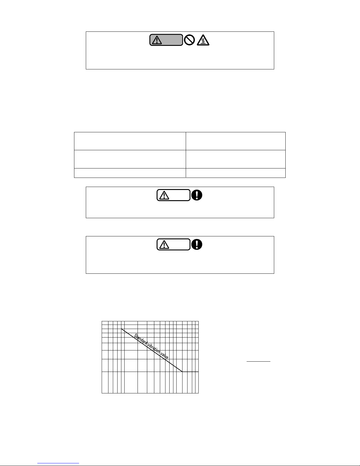
Refer to the following chart for vibration vs. rotation speed.
Rotation speed (min-1)
Standard vibration value at the bearing section
[For reference only]
Relation between the total amplitude (a)
and the vibration velocity (V)
a =
V×6×10
4
π×n
a: Total amplitude (μm)
V: Vibration velocity (mm/s)
n: Equipment rotation speed (min
-1
)
80
60
40
20
10
600 800 1000 1500 2000 3000 4000 6000 8000
100
Total amplitude
(1/1000 mm)
Page 21
4-5
(12) Do not allow a large amount of cutting powder from entering the pump. Failure to observe this
may clog the pump strainer, damage the pump, or significantly deteriorate the performance. If the
pump is used in processes such as grinding, milling, or end milling in which a large amount of
cutting powder is discharged, select the pump carefully.
(13) Stop the pump.
Caution
Keep the cocks of the pressure gauges, compound pressure gages, and
other parts closed all the time except when they are used for
measurement. Otherwise, they become more susceptible to failure.
Caution
Do not run the pump using the power beyond the allowable current value.
Otherwise, the motor may burn out.
Warning
Do not put your fingers or other objects into the opening of the motor.
Otherwise, it may lead to an electrical shock or injury.
Page 22
5-1
5. Maintenance and inspection
Warning
Before checking the pump, be sure to turn off the main power. The pump
may suddenly start up in automatic mode or on other occasions and lead t o
a great danger.
Warning
Before starting the unit or carrying out maintenance/inspection work,
ensure that all the relevant workers are informed of the operation and that
there are no workers in the dangerous zone.
Caution
For overhaul, replacement of parts, or repairs, ask the vendor, the service
center specified by Teral, or your nearest office of Teral. Incorrect work may
cause a failure or accident.
5.1 Precautions for maintenance and inspection
(1) Observe the following points, in particular, during daily inspection.
A large deviation in the pump's discharge pressure, electric current, vibration, noise, or other
conditions from the normal status is a sign of a failure. Therefore, im mediately take measures,
referring to the Maintenance checklist in Section “5.3 Maintenance Checklist”.
For this purpose, it is recommended to keep an operation log.
If the bearing temperature gets abnormally high, immediately stop the pump and check the
bearing. The temperature is normal if the temperature difference between the motor surface
and the atmosphere does not exceed 40°C.
Since shielded grease filled bearings are used, there is hardly any need for maintenance of
the bearings such as refilling of grease. Replace the bearings if they generate unusual noise
or vibration.
* Lithium grease or Urea grease is used as lubricating grease in bearings as below. Use
bearings into which the same type of grease is filled. When you replace the parts, it is
recommended to use a grease equivalent to the following.
・LHW-e: Bearings by NTN (MP-1 grease)
・LPW40/50-e, LKW-e, LFE/LFE-e: Bearing by NSK (EA2 grease), Bearings by NACHI(FNS3D
grease)
・LPW65-e:Urea grease
・LPW-7W 0.75kW:Lithium grease ・1.5kW or more:Urea grease
An oil seal is attached to the bearing section to prevent the entry of liquid. When you replace
a bearing, also replace its oil seal with a new one.
If an oil seal or V-ring is used, high-frequency sound (rubber squeak) may occasionally be
generated, but it is not a pump failure. You can continue to use the pump with the same good
quality.
Keep the cocks of the pressure gauges and compound gauge closed all the time except when
inspection is required.
Page 23
5-2
In the event of a power failure, be sure to turn off the power. The p ump may su d denly start up
on restoration of the power, which lead s to a danger.
Warning
In the event of a power failure, be sure to turn off the power switch.
The pump may suddenly start up on restoration of the power, which leads
to a danger.
(2) Periodically perform cleaning operation as follows:
① Clean any dirt, oil, and other deposits off the outer surface of the coolant pump.
② Cutting powd er deposited in the tank (oil tank) may cause a pump failure. Periodi cally clean
the tank (oil tank).
③ Check the strainer of the pump for any clogging. Clean it if it is clogged.
(3) If you do not use the pump for a long time, observe the following points:
① To prevent possible freezing inside the pump in winter, make sure to take antifreeze measures
such as heat insulation or the installation of a heater to the pump or completely drain the
pump.
② If you have a backup pump, run it from time to time to make it available for operati on at any
time.
5.2 Replacement of the V-ring (for LPW65-e)
Caution
Periodically clean the strainer located on the pump suction side. A cl ogged
strainer may cause pressure fluctuations, a lower discharge rate, unusual
noise, and other problems, thus leading to a pump failure.
Caution
If you do not use the pump for a long time, turn off the power for safety.
Otherwise, accumulated dust may cause heat-generation or ignition.
Caution
The V-ring is an all rub be r seal to prevent, and rotates with friction against
the steel plate in a high speed, which provides a sealing function. When
the pumped liquid contains a large amount of cutting power or the like, the
service life of the V-ring can be shortened . Exchange the V-ring periodically
in the following procedure.
Page 24
5-3
(1) Disassembly procedure
① Remove the coupling cover.
② Remove the coupling bolts (hexagon socket screw) and dismount the coupling.
When dismounting the coupling, remove the knock pin together.
③ Remove the motor mounting bolts connecting the discharge casin g and the motor, and dismount
the motor.
④ Remove the cross-recessed head screws and remove the baffle plate.
⑤ Remove the O-rings and V-ring.
(2) Assembly procedure
① Exchange both the O-ring and the V-ring with new ones.
② After the replacement is completed,. Reassemble the baffle plate (new one), cross-recessed
head screws in the reverse order of disassembly procedure. Apply grease on the sliding part of
the baffle plate when installing it (for lubrication of the V-ring).
③ Mount the motor onto the discharge casing and fasten it with the bolts.
④ Mount the coupling. When mounting the coupling, insert the knock-pin into the main shaft and
holding with the coupling. The coupling bolts and nuts should be temporarily fastened at this
point.
⑤ Lift up the main shaft and insert the fitting plate between the bottom of the coupling and the baffle
plate.
Note
Securely push the V-rin g into the deflector.
Note
Turn the coupling by hand and check if it turns freely without partial
contact. If it does not turn smoothly, repeat the disassembly and
reassembly procedures.
Keep clearance on both sides equal.
① Coupling
② Coupling bolt( hexagon socket screw)
③ Kno ck pin
④ B olt for motor
⑤ Cross-recessed head screw
⑥ Ba ff le pl ate
⑦ O-ring
⑧ V-ring
⑨ Deflector
⑩ Moto r main shaft
⑪ Pum
p
main shaft
Page 25
5-4
⑥ Tighten the coupling bolts in such a manner that clearance on both sides of the coupling will be
nearly equal. Fasten the bolts using a torque wrench with a tightening torque of 40 to 45 Nm. Be
careful as insufficient tightening torque may lead to damage of the pump.
⑦ Remove the fitting plate.
⑧ Turn the coupling by hand and check if it turns freely without partial conta ct. If it does not, rep eat
the disassembly and reassembly procedures.
⑨ Install the coupling cover.
5.3 Maintenance checklist
Inspection interval Consumables
Item
Inspection point Inspection item
Inspection
method
Criterion
(Reference page)
Daily Monthly
Half-
yearly
Yearly
Timing of replacement
(as a guide)*
1
Temperature Measure Between 0 and 40°C (2-2)
-
Humidity Measure Less than 85% RH (2-2)
-
Ambient
conditions
Dust and other
contaminants
Check against the
specified range.
Visual check
No dust or other
contaminants
-
Voltage Measure Specified voltage (2-2)
-
Voltage fluctuation Measure
Within the allowable
fluctuation range (2-2)
-
Power
Power terminal block
Loose screws Retighten
Securely tight ened
-
Clogging
Disassemble and
inspect
No clogging
-
Impeller
Wear
Disassemble and
inspect
No abnormal condition
When worn out
Siphon prevention hole
Clogging
Disassemble and
inspect
No clogging
Main shaft and its
surrounding area
Smooth rotation
Rotate by hand
Rotation is smooth and
uniform (4-1)
-
Bearing
Heat-generation,
abnormal noise,
vibration-
Touch, Listen,
visual check
No abnormal condition(5-1)
3 years
Motor
Oil seals Leakage Visual check- No leakage(5-1)
3 years (when
replacing bearing)
Baffle plate part
(LPW65-e)
Leakage Visual check- No leakage
V-ring/baffle plate:
1 year
O-ring: Whenever
disassembled
O-ring
-
- -
Whenever
disassembled
Others (screws etc.) - - Appearance
Unusual noise,
vibration
Listen
Visual check
No abnormal condition
-
Pump and motor
Insulation resistance
Between the ground
and each lead wire
Megger tester 1 MΩ or more
-
*1 The timing of replacing consumables (as a guide) does not mean their guaranteed service life. The service life of
parts varies depending on the ambient conditions and the conditions for use.
*2 lithium greas e or Urea grease is used as lubricating grease in bearings as below. Use bearings into which the
same type of grease is filled. When you replace the parts, it is recommended to use a grease equivalent to the
following.
LHW-e: Bearings by NTN (MP-1 grease)
LPW40/50-e, LKW-e, LFE/LFE-e: Bearing by NSK (EA2 grease), Bearings by NACHI(FNS3D grease)
LPW65-e:Urea grease
LPW-7W 0.75kW:Lithium grease ・1.5kW or more:Urea grease
Page 26
6-1
6. Troubleshooting
If you find any abnormal conditions of the pump, carefully investigate the problem. For overhaul,
replacement of the parts or rep airs, ask the vendor or contact Teral or our servicing companies.
Problem Cause (Reference page) Action (Reference page)
Wiring is disconnected or broken.
Poor connection or contact of power wires
(3-4)
Check the wires and connections.
Repair or replace.
The power fuse is blown. Replace it with an appropriate fuse.
Tripping of the thermal relay Check the thermal relay.
Contact failure of switching part Check the contact part to repair.
The power voltage is too low. (2-2)
Check the power voltage.
Contact the power company.
The motor has failed. (e.g. broken wire of the
stator winding)
Contact Teral or our servicing companies because
inspection and replacement of the motor are
required.
Foreign matter is caught in the impeller.
The sliding part (liner ring, bearing metal
part) is burning.
The pump does
not start
The bearing is rusty. (5-1)
Contact Teral or our servicing companies because
disassembly and inspection are required.
The pumping liquid contains many bubbles. Prevent the formation and suction of bubbles.
The rotation direction is reverse. (4-2)
Correct the wiring so that the motor rotates in normal
direction. (4-2)
The piping loss is high. Check the diameter, route and length of the pipes.
The piping is clogged with foreign matter. Check and clean the piping.
The impeller is worn.
Foreign matter is accumulated in the impeller
and in the casing.
Contact Teral or our servicing companies because
disassembly and inspection are required.
The rotation speed is low. Check with the tachometer.
The sluice valve is closed. Open the sluice valve.
There is a leak in the discharge pipe. Check and repair the pipe.
The strainer on the suction port is clogged. Check a nd clean the strainer.
The pump starts,
but cannot
achieve the
specified
discharge rate
and the specified
head
The suction port is exposed above the liquid
level.
Adjust the liquid level, for example, by refilling the
tank with the liquid or by lowering the installation
position of the pump.
The rotation speed is too high. Check with the tachometer.
The voltage is too high or too low. (2-2)
Fluctuation of the voltage
Check the power voltage.
Contact the power company.
A 50Hz pump is run in the 60Hz power zone. Check the n ameplate.
The stator winding is broken, shorted, or
grounded.
The stator and rotor are in contact due to
wear of the bearing. (5-1)
A rotating part is in contact with another part.
Contact Teral or our servicing companies because
disassembly and inspection are required.
The motor is running in open-phase
condition.
Check the wiring.
The specific gravity or the dynamic viscosity
of the pumping liquid is too high. (2-2)
Use a liquid with low specific gravity and low
dynamic viscosity.
Overload and
overcurrent of the
motor
The discharge rate is high.
Throttle the sluice valve to adjust the rate as per the
specifications.
Page 27
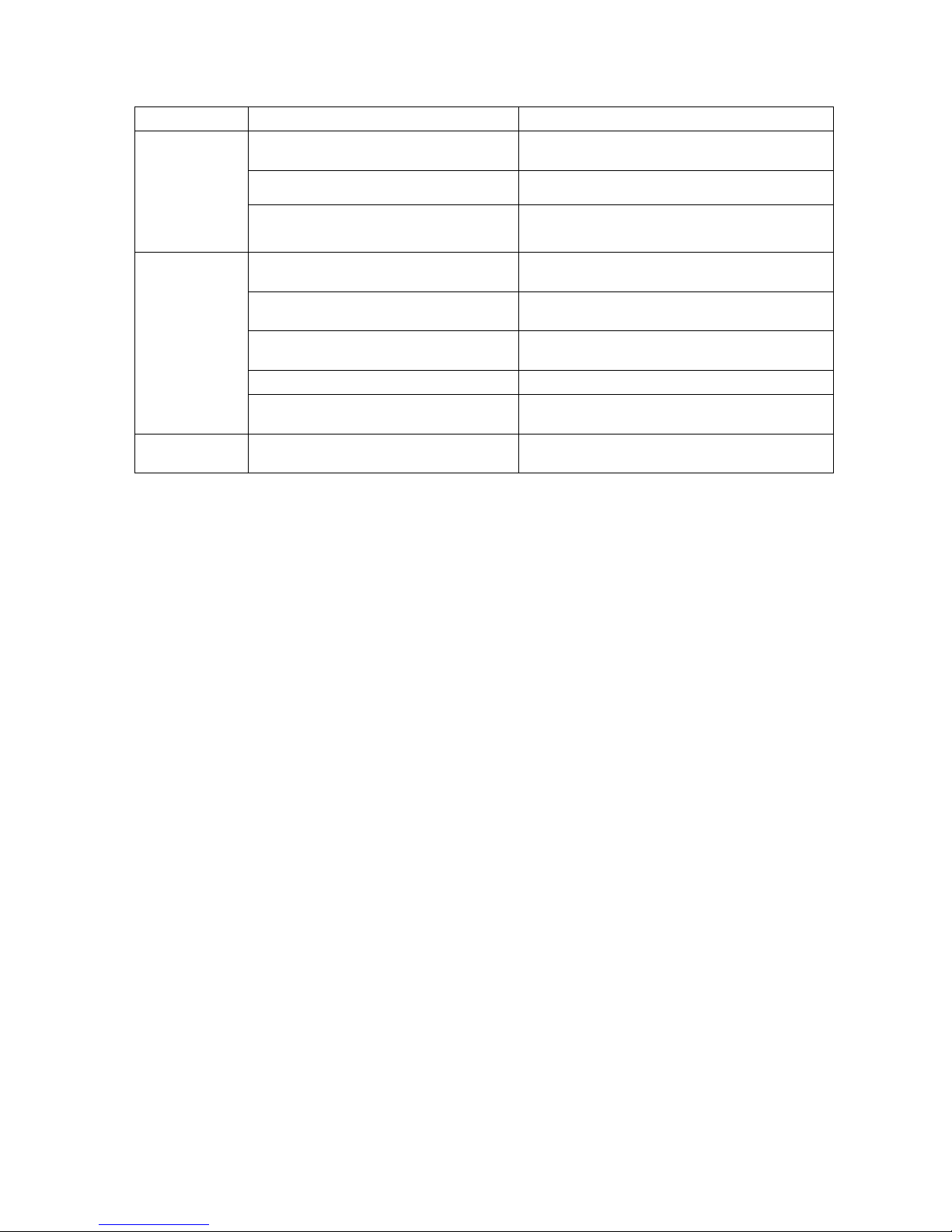
6-2
Problem Cause (Reference page) Action (Reference page)
The bearing is worn or damaged. (5-1)
Contact Teral or our servicing companies because
disassembly and inspection are required.
The grease is deteriorated. (5-1) Replace the bearing. (5-1)
Overheat of
bearing
Incorrect installation of the pump and the
piping (3-1)
Check and correctly install them.
The bearing is worn or damaged. (5-1)
Contact Teral or our servicing companies because
disassembly and inspection are required.
The motor is running in open-phase
condition.
Check the wiring.
The impeller is clogged with foreign matter,
thus leading to imbalanced load.
Contact Teral or our servicing companies because
disassembly and inspection are required.
Cavitation has occurred. Consult Teral or our servicing companies.
Unusual noise
and unusual
vibration of the
pump
Incorrect installation of the pump and the
piping (3-1)
Check and correctly install them.
Water hammer
occurs
Hammering has occurred when the valve is
rapidly opened and closed.
Provide a pressure damper (e.g. accumulator).
Page 28
TP-462-01
Head Office
230, Moriwake, Miyuyki-cho, Fukuyama-city, Hiroshima, 720-0003, Japan
Tel.084-955-1111 Fax.084-955-5777
Overseas Div.
TERAL Koraku Bldg., 2-3-27, Koraku, Bunkyo-ku, Tokyo, 112-0004, Japan
Tel.03-3819-6890 Fax.03-3818-6790
 Loading...