

Page 1
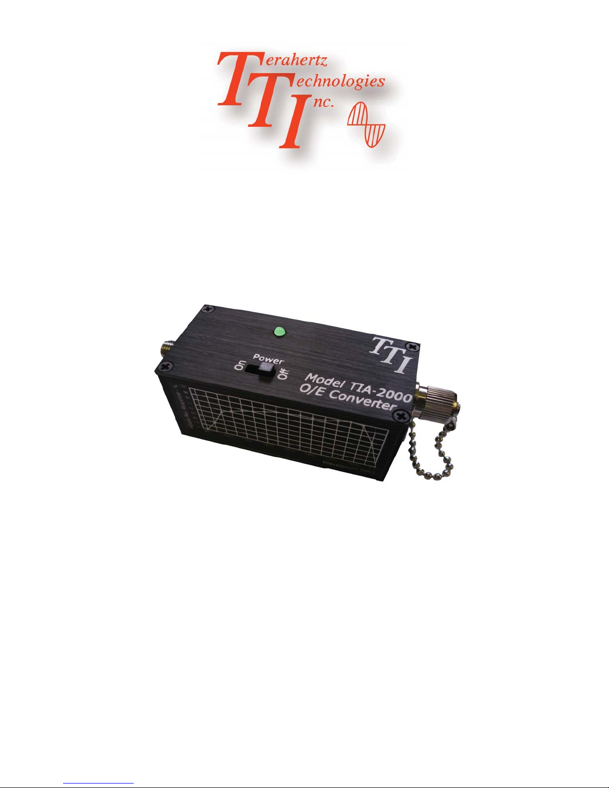
TIA-2000
Optical/Electrical Converter
Terahertz Technologies Inc.169 Clear Road Oriskany NY 13424 (315) 736-3642 FAX (315) 736-4078
Operating Instructions
E-mail [email protected]
6/2011
Page 2

Contents
Introduction.............................................................................................................................................1
Unpackaging and Inspection..................................................................................................................1
Power Supply.........................................................................................................................................1
Typical Setup..........................................................................................................................................2
Operating Considerations.......................................................................................................................2
Typical Frequency Response..................................................................................................................3
Typical Spectral Response ....................................................................................................................3
Specifi cations.........................................................................................................................................2
Service/Warranty Information.................................................................................................................5
Page 3

Introduction
The TIA-2000 Optical to Electrical Converter is a wide-band detection system for fi ber optic applica-
tions. With a typical bandwidth of DC to 20 GHz, it accurately provides an electrical replica of the
optical signal presented to it. It is intended to drive a 50 ohm cable terminated in its characteristic
impedance.
The unit is equipped with an InGaAs/InP detector that is responsive in the wavelength range of 1250-
1625 nm. The TIA-2000 is provided with an FC/UPC fi ber optic receptacle. Other fi ber optic connec-
tors can be provided on request. The output signal is presented to a type K SMA female connector.
Unpacking and Inspection
Prior to shipment this instrument was inspected and found to be free of mechanical and electrical
defects. Upon acceptance by the carrier he assumes responsibility for its safe arrival. After unpack-
ing, examine the unit for any evidence of shipping damage. Should you receive this instrument in a
damaged condition, apparent or concealed, it must be noted on the freight bill or express receipt and
signed by the carrier’s agent. Failure to do so could result in the carrier refusing to honor the claim.
Upon fi ling a claim TTI should be notifi ed.
Power Supply
Each unit comes equipped with a 9 V regulated power supply that provides power to the unit. Simply
plug the power supply output cable into the receptacle located beneath the FC fi ber optic connector.
It is recommended that the user never attempt substitution of this unit with any other power supply.
Reverse polarity or voltages other than 9 Volts may irreparably damage the unit. The power supply
can be used with mains of either 120 or 240 VAC, 50-60 Hz. Several replaceable power plug adaptors
are supplied for use in various countries.
Page 1
Page 4
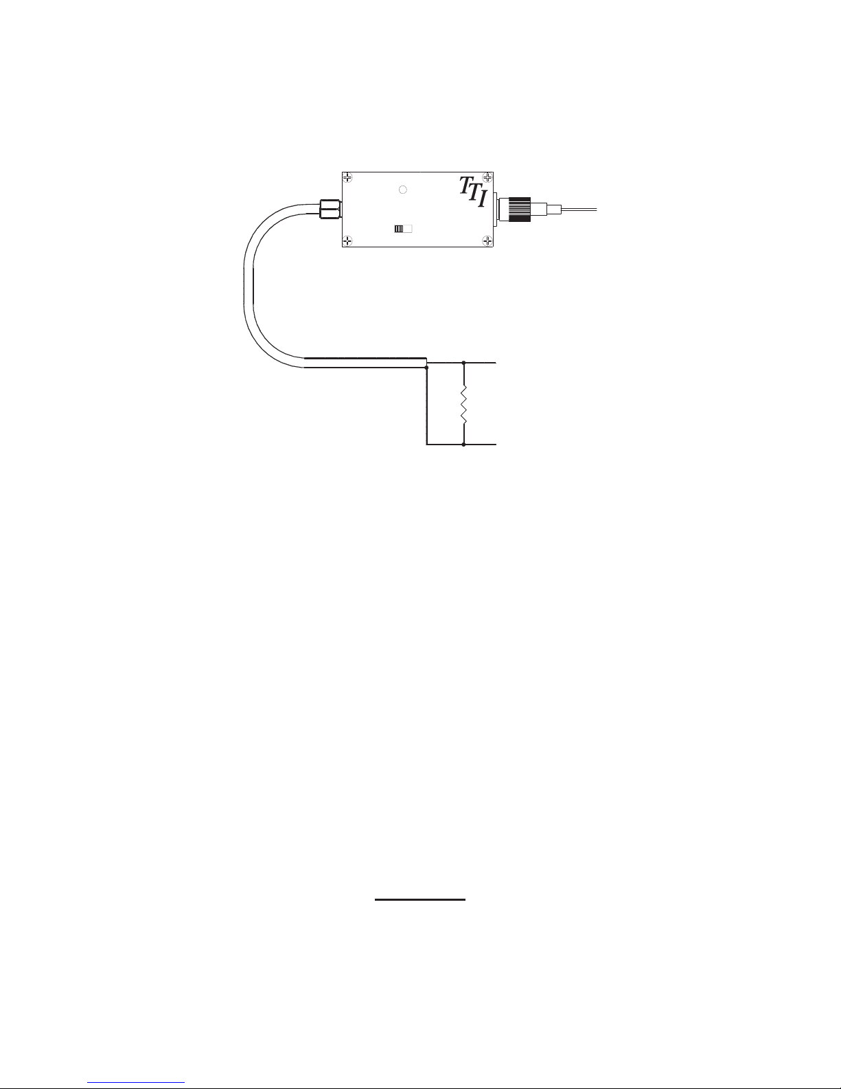
Typical Setup of the TIA-2000
“K” Connector
Power
Model TIA-2000
On
Off
O/E Converter
User Supplied RF
Output Cable - 50 Ohm
Signal
FC Connector
Ω
Operating Considerations
The TIA-2000 is comprised of a fi ber coupled InGaAs detector coupled with a reverse bias voltage network.
The ouput of the diode is brought out to a type K female SMA connector. Light falling on the detector generates
a positive-going proportional current. This current, multiplied by the load impedance produces a voltage that is
proportional to the light incident on the detector surface.
Normally the unit is used to drive a coaxial cable, this cable should have a 50 ohm characteristic impedance and
be terminated with a 50 ohm load at the oscilloscope or other measuring device to be used.
Typical optical return loss is 35 dB and is caused primarily by the FC/PC connector employed. If higher return
loss is needed, The unit may be optionally equipped with singlemode angled PC connectors for ORLs of around
52 dB.
Warning!
No voltage should be present at user interface or damage to the unit may occur.
Page 2
Page 5
Typical Frequency Response
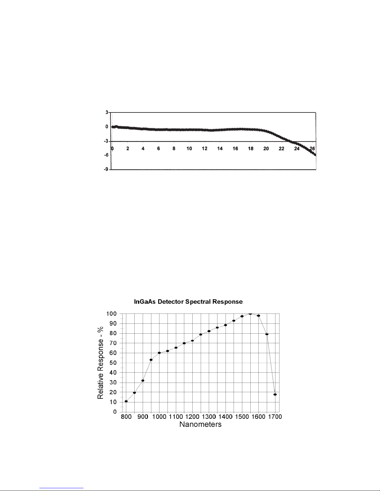
The bandwidth of the TIA-2000 is from DC to typically 20 GHz (-3 dB ). Refer to the following Bode plot
{dB}
Response
Relative Power
Frequency {GHz}
Spectral Response
The approximate relative response curves of the detectors employed is as shown below. Note that these are re-
esentative curves and do not necessarily correspond to the exact response on the particular detector in use.
Page 3
Page 6

TIA-2000 Specific ations
Detector Type InGaAs/InP (900 - 1700nm)
Current Responsivity
Maximum Linear Input Power 3mw
Maximum Input Power without Damage
Bandwith-(3dB) DC to 20 GHz Typ, 18 GHz min.
Output Impedance 50 Ohms
Output Connector Type K SMA Female
Fiber Optic Input Connector FC/UPC or FC/APC
Input Numerical Aperture 0.11 (9/125μ Singlemode Optical Fiber)
Optical Return Loss >35dB, >52dB with APC Connection
Electrical Return Loss 10 dB
Power Universal Power Supply
0.8 A/ W @ 1550nm Typical
10mw
Dimensions 1.2”W x 2.5”L x 1.3”H ( 30.5mm x 63mm x 33mm)
Weight 5.6 oz (0.16Kg)
LED Annunciators Provided Power On
Operating Temperature Range 0 - 40 C
Standard Warranty Two Years, Component and Workmanship, 30 Day Satisfaction Guarantee
Accessories Supplied Transit /Storage Case, Operating Manual, Universal Power Su pply
TTI reserves the right to change specifi cations without notice.
Page 4
Page 7

LIMITED WARRANTY
TERAHERTZ TECHNOLOGIES INC. (“TTI”) WARRANTS THAT TO THE FIRST PURCHASER, FOR A PERIOD
OF TWO YEARS FROM THE DATE OF RECEIPT, THAT THIS PRODUCT (“THE PRODUCT”) WILL BE FREE
FROM DEFECTS IN MATERIALS AND MANUFACTURING. THE FOREGOING WARRANTY IS THE ONLY
WARRANTY, EXPRESS OR IMPLIED, GIVEN BY TTI, I.E., THERE IS NO WARRANTY OF FITNESS FOR A
PARTICULAR PURPOSE. TTI HEREBY DISCLAIMS ANY EXPRESS OR IMPLIED WARRANTY OTHER THAN
THE WARRANTY IN THE FIRST SENTENCE TO THE FULLEST EXTENT PERMITTED BY LAW.THE SOLE AND
EXCLUSIVE REMEDY UNDER THIS WARRANTY IS REPAIR OR REPLACEMENT AT TTI’S OPTION OF ANY
PRODUCT THAT PROVES TO BE DEFECTIVE IN MATERIALS OR MANUFACTURING WITHIN TWO YEARS
OF RECEIPT OF THE PRODUCT. NOTE: THIS WARRANTY DOES NOT APPLY TO ANY PRODUCT WHICH HAS
BEEN SUBJECT TO MISHANDLING, MISUSE, OR SERVICE BY UNAUTHORIZED PERSONNEL OR TO ANY
PRODUCT WHICH HAS BEEN DAMAGED, MODIFIED, ALTERED OR TAMPERED WITH. TO THE FULLEST
EXTENT OF THE LAW, TTI DISCLAIMS ALL LIABILITY FOR ANY OTHER DIRECT, INCIDENTAL OR CONSEQUENTIAL DAMAGES ALLEGED TO BE CAUSED BY A DEFECTIVE PRODUCT, I.E., TTI WILL NOT BE
RESPONSIBLE FOR ANY PERSONAL INJURY, PROPERTY DAMAGE OTHER THAN THE COST OF REPLACING THE PRODUCT OR ANY OTHER MONETARY DAMAGE SUCH AS LOST WAGES OR PROFITS CAUSED
BY ANY USE, ATTEMPTED USE OR INABILITY TO USE THE PRODUCT. NOTE: BY USING THE PRODUCT,
YOU AGREE THAT REPAIR OR REPLACEMENT AT TTI’S OPTION WILL FULLY SATISFY TTI’S WARRANTY
OBLIGATION TO YOU, WHETHER IN CONTRACT, TORT, NEGLIGENCE, STRICT
Repair Information
Products manufactured by Terahertz Technologies Inc. are designed and fabricated to provide reliable
performance. However, in the event that service is required, both telephone technical assistance and
factory repair services are available. Call (315) 736-3642 for information.
For IN-WARRANTY REPAIRS, call us to obtain a Returned Material Authorization number, (RMA
Number). All products are to be returned to TTI with freight charges pre-paid. Those products sent
under warranty will be returned to our customers pre-paid. We cannot be responsible for returned
products that do not reference the TTI RMA number.
For OUT-OF-WARRANTY repairs, services are billable for both time and materials.
Calibration - This is a qualitative measurement device. No calibration is required or necessary.
Page 5
 Loading...