

Terahertz Technologies TIA-1200 Operating Instructions Manual
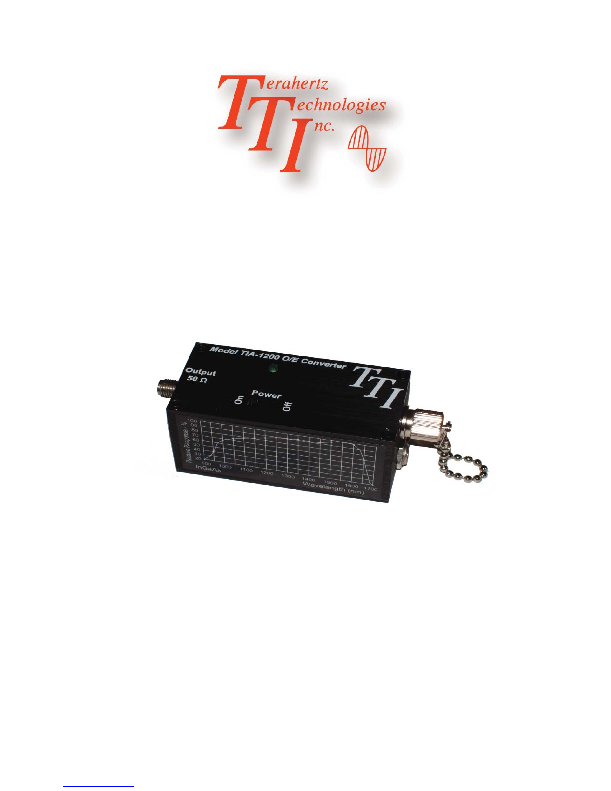
TIA-1200
Optical/Electrical Converter
Terahertz Technologies Inc.169 Clear Road Oriskany NY 13424 (315) 736-3642 FAX (315) 736-4078
Operating Instructions
E-mail sales@terahertztechnologies.com
5/2013

Contents
Introduction...................................................................................................................................1
Unpackaging and Inspection........................................................................................................1
Power Supply...............................................................................................................................1
Typical Setup................................................................................................................................2
Operating Considerations.............................................................................................................2
Typical Frequency Response.......................................................................................................3
Spectral Response.......................................................................................................................3
Specifi cations...............................................................................................................................4
Service/Warranty Information.......................................................................................................5

Introduction
The TIA-1200 Optical to Electrical Converter is a wide-band detection system for fi ber optic applica-
tions. With a typical bandwidth of DC to 12 GHz, it accurately provides an electrical replica of the
optical signal presented to it. It is intended to drive a 50 Ohm cable terminated in its characteristic
impedance. The unit is equipped with an InGaAs/InP detector that is responsive in the wavelength
range of 900 - 1700 nm. The TIA-1200 is provided with an FC fi ber optic receptacle. Other fi ber optic
connectors can be provided on request. The output signal is presented to a type K SMA female con-
nector.
Calibration - This is a qualitative measurement device. No calibration is required or necessary.
Unpacking and Inspection
Prior to shipment this instrument was inspected and found to be free of mechanical and electrical
defects. Upon acceptance by the carrier he assumes responsibility for its safe arrival. After unpack-
ing, examine the unit for any evidence of shipping damage. Should you receive this instrument in a
damaged condition, apparent or concealed, it must be noted on the freight bill or express receipt and
signed by the carrier’s agent. Failure to do so could result in the carrier refusing to honor the claim.
Upon fi ling a claim TTI should be notifi ed.
Power Supply
Each unit comes equipped with a 9 V regulated power supply that provides power to the unit. Simply
plug the power supply output cable into the receptacle located beneath the FC fi ber optic connector.
It is recommended that the user never attempt substitution of this unit with any other power supply.
Reverse polarity or voltages other than 9 Volts may irreparably damage the unit. The power supply
can be used with mains of either 120 or 240 VAC, 50-60 Hz. Several replaceable power plug adaptors
are supplied for use in various countries.
Page 1
 Loading...