

Teradyne Z1880-2, Z1880-1, Z1866, Z1860-NB, Z1888 Site Preparation Manual
...
Z1800-Series
Site Preparation Guide
Teradyne, Inc.
Assembly Test/Walnut Creek
2625 Shadelands Drive
Publication Number 1800M123 Copyright Teradyne, Inc.
●
Walnut Creek, CA 94598-2597

Product Warranty
Trademarks
THE STANDARD TERADYNE WARRANTY CONSTITUTES THE ONLY REPRESENTATION OR
WARRANTY MADE BY TERADYNE WITH RESPECT TO ANY EQUIPMENT, GOODS OR
SERVICES SUPPLIED BY TERADYNE. TERADYNE MAKES NO OTHER WARRANTIES OR
REPRESENTATIONS, EXPRESSED OR IMPLIED, IN FACT OR IN LAW, INCLUDING THE
IMPLIED WARRANTIES OF MERCHANTABILITY AND FITNESS FOR A PARTICULAR
PURPOSE. IN NO EVENT WILL TERADYNE BE LIABLE FOR INCIDENTAL, SPECIAL OR
CONSEQUENTIAL PENALTIES OR DAMAGES, INCLUDING LOST PROFITS, OR PENALTIES
AND/OR DAMAGES FOR DELAY IN DELIVERY OR FAILURE TO GIVE NOTICE OF DELAY,
EVEN IF TERADYNE HAS BEEN ADVISED OF THE POSSIBILITY OF SUCH DAMAGES.
Due to an ongoing policy of constantly updating equipment and procedures, the contents of this
document are subject to change without notice.
Teradyne assumes no responsibility for errors or for any damages that result from the
implementation of the procedures described in this publication. Teradyne also reserves the right to
make changes in its products without incurring any obligation to incorporate such changes in units
previously sold or shipped. Teradyne makes no commitment to update nor to keep current the
information contained in this document.
Teradyne assumes no responsibility for the use of any circuitry other than the circuitry embodied as
a Teradyne product. No other circuit patent licenses are implied.
This software system consists of computer software and documentation. It contains trade secrets
and confidential information which are proprietary to Teradyne, Inc. Its use or disclosure in whole or
in part without the express written permission of Teradyne, Inc. is prohibited.
This software system is also an unpublished work protected under the copyright laws of the United
States of America. If this work becomes published, the following notice shall apply:
Copyright © 1998 Teradyne, Inc. All Rights Reserved.
The following are trademarks or registered trademarks of Teradyne and may be used to describe
only Teradyne, Inc., Assembly Test/Walnut Creek products:
APC
AutoLoad
AutoLocate
BoardWatch
Boundary Scan Intelligent
Diagnostics (BSID)
CapScan
Component Designer (CDES)
DeltaScan
FrameScan
FrameScan Plus
HostLink
Inline Device Programmer
(ILDP)
InterScan
MultiScan II
PentaVision
PRISM
ProcessWatch
Programmer Efficiency
Package (PEP)
Quick-Check
Safecracker
Spectrum 8800-Series
T est Toolbox
Tester-Aided Instruction
TestQA
VICTORY
VP/VXI
WaveScan
Z1800-Series
Borland and Paradox are trademarks of Borland International, Inc.
C++ and UNIX are registered trademarks of AT&T Bell Laboratory.
Codewright is a trademark of Premia Corporation.
ETHERNET is a trademark of Xerox Corporation.
FABmaster is a registered trademark of FABMASTER S.A.
HP-UX is a registered trademark of Hewlett-Packard Company.
IBM, MicroChannel, and PS/2 are registered trademarks of International Business Machines, Inc.
LabWindows, LabWindows/CVI, NI-488.2, and NI-VXI are trademarks of National Instruments
Corporation.
Microsoft, MS-DOS, QuickC, Windows 95, and WindowsNT are either registered trademarks or
trademarks of Microsoft Corporation in the United States and/or other countries.
Okidata and Microline are registered trademarks of Oki Electric Industry Company, Ltd.
OS-9 and Microware are registered trademarks of Microware Systems Corporation.
SunOS and Solaris are registered trademarks of Sun Microsystems, Inc.
VAX and VMS are registered trademarks of Digital Corporation.

Z1800-S
Manual History
ERIES
S
P
ITE
REPARATION
Fourth Edition, September 1998
Z1888 and Z1803 information added
Third Edition, January 1997
Change to vacuum requirement
Second Edition, May 1996
Changes to tester power requirements in the "Plan the Tester Site" and "Z1800-Series
Site Preparation Checklist" sections
First Edition, April 1996
G
UIDE
Additional copies of this manual may be obtained from Teradyne.
Publications No. 1800M123
© 1996, 1997, 1998 Teradyne Inc., Assembly Test/Walnut Creek
2625 Shadelands Drive . Walnut Creek, CA 94598 . (925) 932.6900
Customer Service Hotline (800) 457-8326

C
ONTENTS
Z1800-Series Site Preparation Guide
Planning the Tester Site......................................................................... 1
General Specifications ..................................................................... 2
Z1890............................................................................................... 3
Z1888............................................................................................... 4
Z1884............................................................................................... 5
Z1880 Plus: Z1880-1 and Z1880-2 .................................................. 6
Z1866............................................................................................... 7
Z1860-NB......................................................................................... 8
Z1860 LCT ....................................................................................... 9
Z1860............................................................................................. 10
Z1850............................................................................................. 11
Z1840............................................................................................. 12
Z1820............................................................................................. 13
Z1805 and Z1808........................................................................... 14
Z1803 Plus: Z1803-1 and Z1803-2 ................................................ 15
Z1800............................................................................................. 16
PRISM-Z Option............................................................................. 17
Uncrating and Positioning the Tester................................................... 18
Z1890, Z1888, Z1880, Z1808, Z1805 and Z1803 Plus with the
PRISM-Z Option............................................................................. 18
Z1890, Z1880, Z1808, and Z1805 ................................................. 20
Z1884............................................................................................. 20
Z1860, Z1860-NB, Z1850, Z1840, Z1820, and Z1800................... 21
Vacuum System Design....................................................................... 23
Environmental Requirements......................................................... 23
Vacuum System Installation Types................................................ 23
Pipe Selection ................................................................................ 27
Valve Selection and Placement ..................................................... 28
Gauge Placement .......................................................................... 28
Vacuum System Installation........................................................... 29
Leak Testing................................................................................... 30
Computer Requirements...................................................................... 30
Board Assignment Recommendations................................................. 31
Z1800-Series Site Preparation Checklist

•
•
•
•
•
•
•
•
•
Z1800-S
Planning the T ester Site
ERIES
Note: Systems Currently in Production
S
P
ITE
REPARATION
The Z1800-Series Site Preparation Guide contains site requirements and system
specifications for the Z1800-Series test systems and vacuum pump options. It also provides
details for the installation of vacuum systems for one or many test systems.
The last page is a checklist for Teradyne customers and field personnel to help determine if
the location is ready for a new tester installation.
In a busy production environment, place the tester near the main flow of boards in the
assembly line. The board repair and fixture storage areas should be located nearby. In lowto-medium production rate areas, provide ample room for carts containing board boxes and
movement of product to and from the tester.
AC power cords for all testers are 15 feet long with an NEMA L5–30P connector. Locate
your tester within 10 feet of a source of 47–63 Hz, single-phase AC power. In locations
outside of the United States, adjust the line conditioner transformer to the local AC line
voltage. The transformer has taps to accommodate incoming voltages between 100 and 240
VAC. Refer to your tester-specific system reference for information on adjusting the line
conditioner taps.
Position your printer and computer close to the tester. The following is a list of Bosch
Frame accessories/options for mounting the printer, the computer, the mouse or track ball,
and other items. Dimensions shown will add to the overall system footprint. All options
will fit within the specified Service Access boundary.
Bosch Frame Tilt Option, PN 046-932-01
Tabletop Extension (9 in. x 48 in., non-tilted), PN 046-937-01
Tabletop Extension (9 in. x 48 in., 15-degree tilt), PN 046-937-02
Tabletop Extension for Optional Bays (9 in. x 38 in.), PN 046-940-00
Tabletop Extension for Mouse or Track Ball (9 in. x 15 in., non-tilted),
PN 046-943-01
Tabletop Extension for Mouse or Track Ball (9 in. x 15 in., tilted),
PN 046-943-01
Printer Shelf (8 in. x 14 in., tilted)
Computer Mounting Frame
Rear Shelf (9 in. x 48 in.)
G
UIDE
Z1888, Z1884, Z1860-NB, and Z1803 Plus.
If your plant has a central vacuum supply, locate your tester within 10 feet of a vacuum
outlet. If your plant does not have a central vacuum supply, Teradyne’s 41 CFM vacuum
pump is available as an option.
2
General Specifications
Testers Item Specified
Teradyne
Provides
AC MAINS Z1860-NB, Z1880, Z1884,
Z1888, Z1890
Z1800, Z1803, Z1805, Z1808,
Z1820, Z1840, Z1850, Z1860,
Z1860 LCT, Z1866
AC MAINS Circuit Breaker Z1860-NB, Z1880, Z1884,
Z1888, Z1890
Z1800, Z1803, Z1805, Z1808,
Z1820, Z1840, Z1850, Z1860,
Z1860 LCT, Z1866
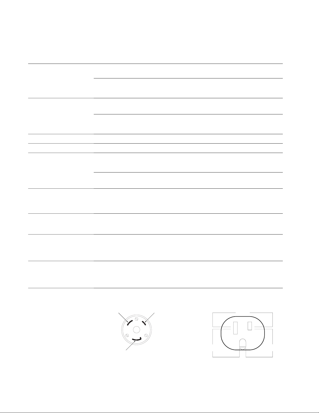
AC MAINS Receptacle All models
AC MAINS Cord Connector All models
Main AC Input Breaker Z1803, Z1805, Z1808,
Z1860-NB, Z1880, Z1884,
Z1888, Z1890
Z1800, Z1820, Z1840, Z1850,
Z1860, Z1866, Z1860 LCT
Vacuum Supply All models
Vacuum Pump Power All models using Teradyne’s
41 CFM vacuum pump
100–240VAC, 3.0kVA, 3-wire, 50–60Hz (range of 47–
63Hz), single-phase
100–240VAC, 1.8kVA, 3-wire, 50–60Hz (range of 47–
63Hz), single-phase
• 100–130VAC requires minimum of 25A breaker
• 200–240VAC requires minimum of 13A breaker
• 100–130VAC requires minimum of 15A breaker
• 200–240VAC requires minimum of 7.5A breaker
NEMA L5-30R
NEMA L5-30P
• 100–130 VAC requires 25A breaker PN 090-156-00
• 200–240 VAC requires 13A breaker PN 090-186-00
• 100–130 VAC requires 15A breaker PN 087-11X-00
• 200–240 VAC requires 7.5A breaker PN 087-12X-00
41 CFM pump capacity recommended.
1 in. NPT male thread within 10 ft. of system.
Minimum vacuum lev el of 20 in. of mercury available to
the system at all times.
Line voltage of 190–460 VAC, 2.2 kVA, 30 Amp , 4-wire,
50 or 60Hz, 3-phase.
X
X
X
X
X
Vacuum Power Connectors All models
Environmental Requirements All models
AC MAINS Wiring Color Codes AC Outlets on Tester
Brown (HOT) Blue (NEUTRAL)
Green (GROUND)
• Low Voltage 190–230 VAC uses 250 VAC, 20 Amp,
4-wire, NEMA L15-20P
• High Voltage 380–460 VAC uses 480 VAC, 20 Amp,
4-wire, NEMA L16-20P
Ambient temperature: 64˚–89˚F (18˚–32˚C)
Relative humidity: 20–70% non-condensing
Vacuum pump operating temperature range: 32˚–
122˚F (0˚–50˚C)
120 Volts
NEUTRAL HOT
Less than
1 Volt
GND
X
120
Volts
3
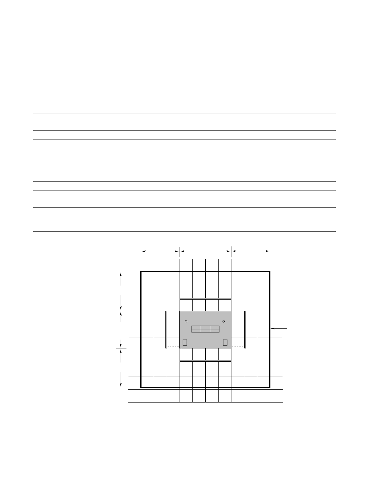
Z1890
Uncrated Dimensions
Crate Dimensions
Weight Crated (approximate) 1225 lb (556 kg)
Weight (approximate)
AC MAINS
AC MAINS Circuit Breaker
AC MAINS Receptacle
AC MAINS Cord Connector
Main AC Input Breaker
Vacuum Supply
Vacuum Pump Power
Vacuum Power Connectors
Environmental Requirements Ambient temperature: 64˚–89˚F (18˚–32˚C)
Note:
Also see “PRISM-Z Option” on page 17 if applicable.
32.5 in. (83 cm) H x 34.5 in. (88 cm) D x 48 in. (122 cm) L
62 in. (158 cm) H x 45 in. (114 cm) D x 59 in. (150 cm) L
1000 lb (454 kg)
100–240VAC, 3.0kVA, 3-wire, 50–60Hz (range of 47–63Hz), single-phase
• 100–130VAC requires minimum of 25A breaker
• 200–240VAC requires minimum of 13A breaker
NEMA L5-30R
NEMA L5-30P
• 100–130 VAC requires 25A breaker PN 090-156-00
• 200–240 VAC requires 13A breaker PN 090-186-00
41 CFM pump capacity recommended. 1 in. NPT male thread within 10 ft. of system.
Minimum vacuum level of 20 in. of mercury available to the system at all times.
Line voltage of 190–460 VAC, 2.2 kVA, 30 Amp, 4-wire, 50 or 60Hz, 3-phase.
• Low Voltage 190–230 VAC uses 250 VAC, 20 Amp, 4-wire, NEMA L15-20P
• High Voltage 380–460 VAC uses 480 VAC, 20 Amp, 4-wire, NEMA L16-20P
Relative humidity: 20–70% non-condensing
Vacuum pump operating temperature range: 32˚–122˚F (0˚–50˚C)
Teradyne Provides
X
X
X
X
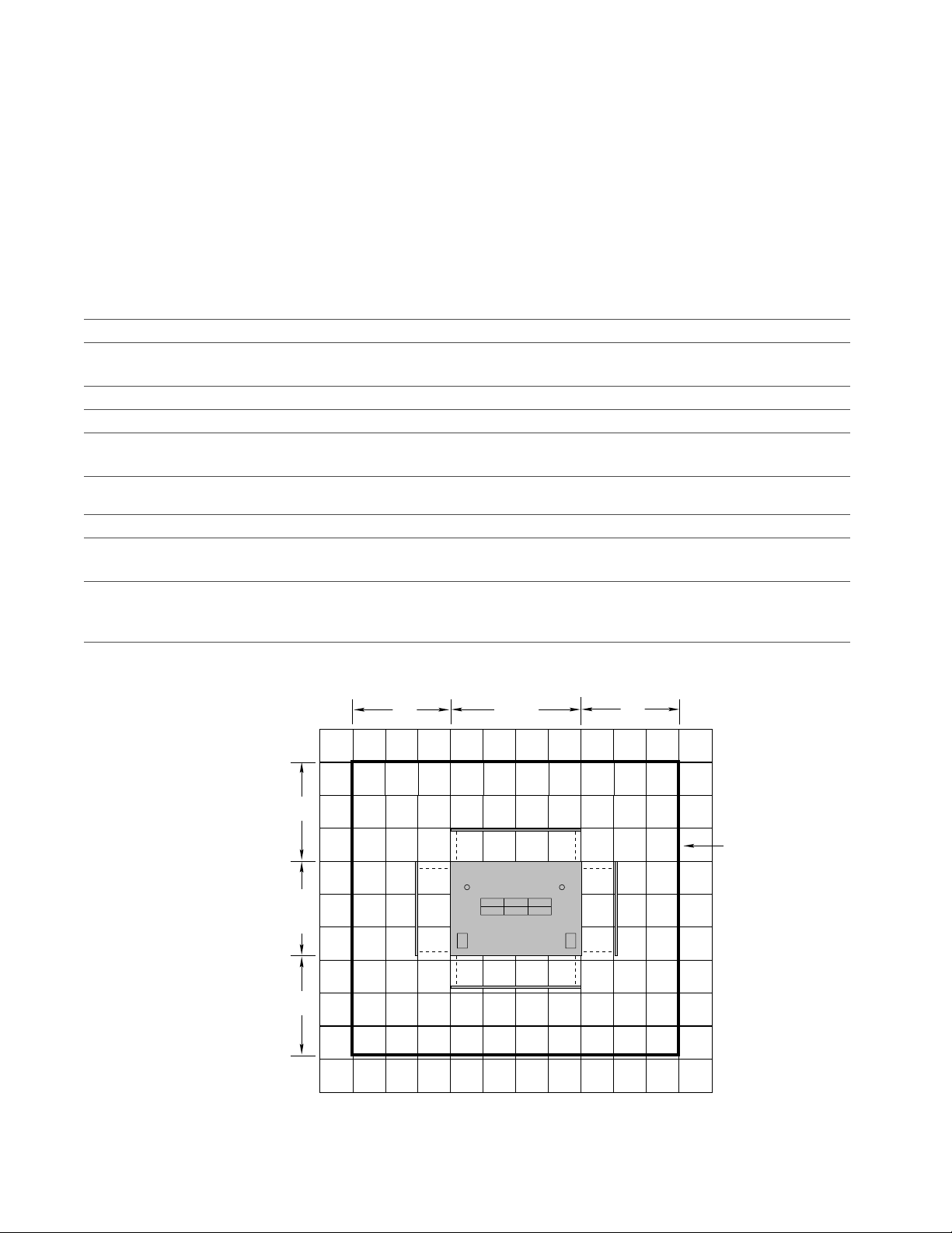
Floor Space Required
36"36"
34.5"
88 cm
36"
48"
122 cm
36"
36” service
36" service
access
boundary
access
Z1800-Series Site Preparation Guide
4
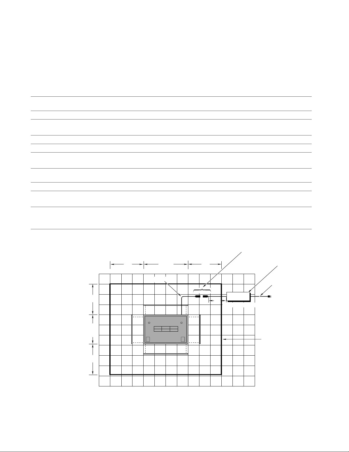
Z1888
Uncrated Dimensions
Crate Dimensions
32.5 in. (83 cm) H x 34.5 in. (88 cm) D x 48 in. (122 cm) L
62 in. (158 cm) H x 45 in. (114 cm) D x 59 in. (150 cm) L
Weight Crated (approximate) 1225 lb (556 kg)
Weight (approximate)
External AC Power
1000 lb (454 kg)
8.5 in. (21cm) H x 22.5 in. (57cm) D x 8.5 in. (21cm) L
Line Conditioner
AC MAINS
AC MAINS Circuit Breaker
100–240VAC, 3.0kVA, 3-wire, 50–60Hz (range of 47–63Hz), single-phase
• 100–130VAC requires minimum of 25A breaker
• 200–240VAC requires minimum of 13A breaker
AC MAINS Receptacle
AC MAINS Cord Connector
Main AC Input Breaker
NEMA L5-30R
NEMA L5-30P
• 100–130 VAC requires 25A breaker PN 090-156-00
• 200–240 VAC requires 13A breaker PN 090-186-00
Vacuum Supply
41 CFM pump capacity recommended. 1 in. NPT male thread within 10 ft. of system.
Minimum vacuum level of 20 in. of mercury available to the system at all times.
Vacuum Pump Power
Vacuum Power Connectors
Line voltage of 190–460 VAC, 2.2 kVA, 30 Amp, 4-wire, 50 or 60Hz, 3-phase.
• Low Voltage 190–230 VAC uses 250 VAC, 20 Amp, 4-wire, NEMA L15-20P
• High Voltage 380–460 VAC uses 480 VAC, 20 Amp, 4-wire, NEMA L16-20P
Environmental Requirements Ambient temperature: 64˚–89˚F (18˚–32˚C)
Relative humidity: 20–70% non-condensing
Vacuum pump operating temperature range: 32˚–122˚F (0˚–50˚C)
Teradyne Provides
X
X
X
X
X
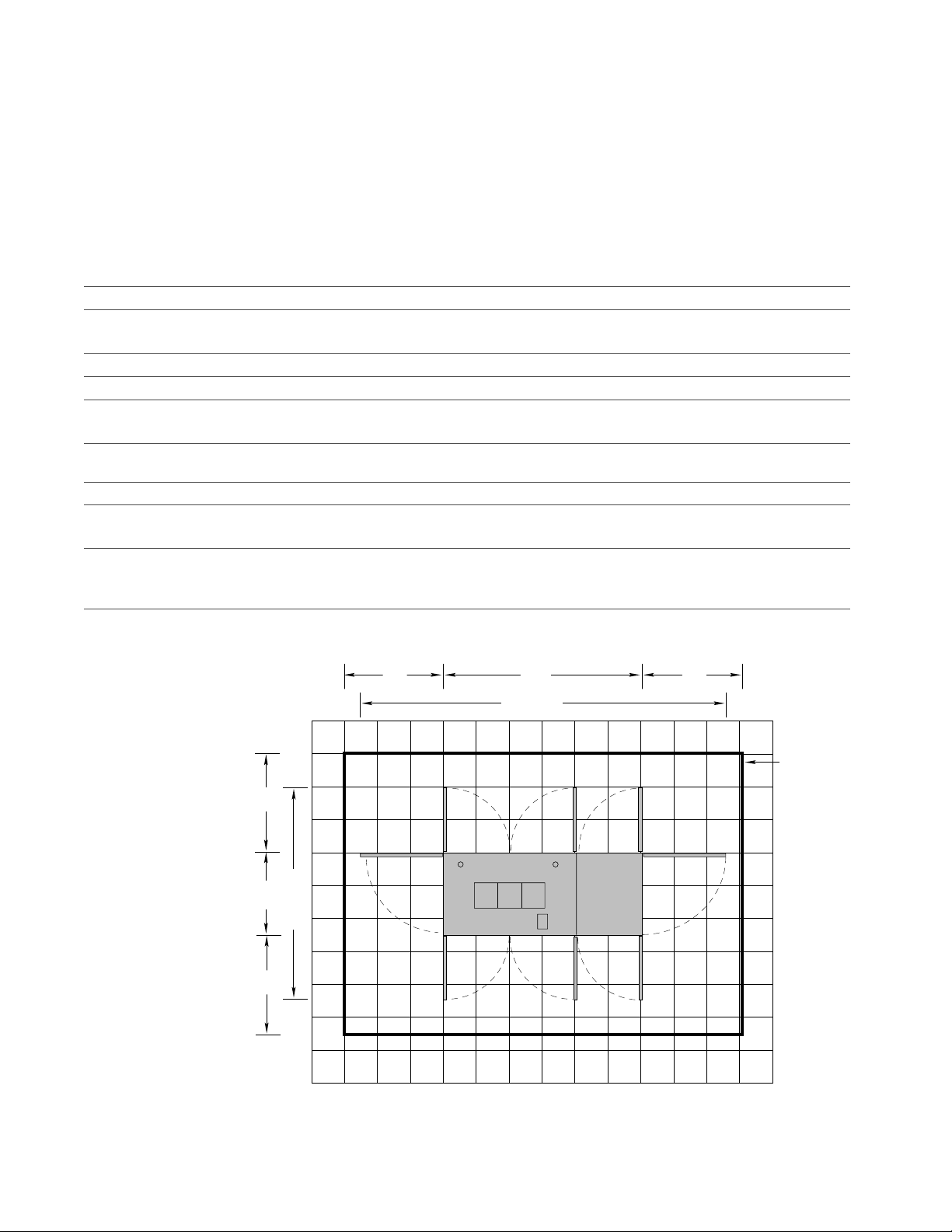
Floor Space Required
Important:
Note: Bosch-Frame systems use connector which is approximately
36"
34.5"
36"
88 cm
36"
3-4 inches in diameter and 10-12 inches in lenth when connected.
This connector is not used on Z1840 and Z1860 PRIZM-Z installations.
48"
122 cm
15' Cord
Connector is approximately 3.5“ in diameter
and 11“ in length when connected.
36"
Conditioner
12''
See EMF Caution
AC Line
8.5"H × 22.5"D × 8.5"L
15' Cord
To AC Mains
36" service
access and
EMF
perimeter
The AC line conditioner must be a minimum of 36“ from the system console. If it is within the 36“ EMF
service perimeter, degradation of analog (PRISM-Z) measurements may occur.
5
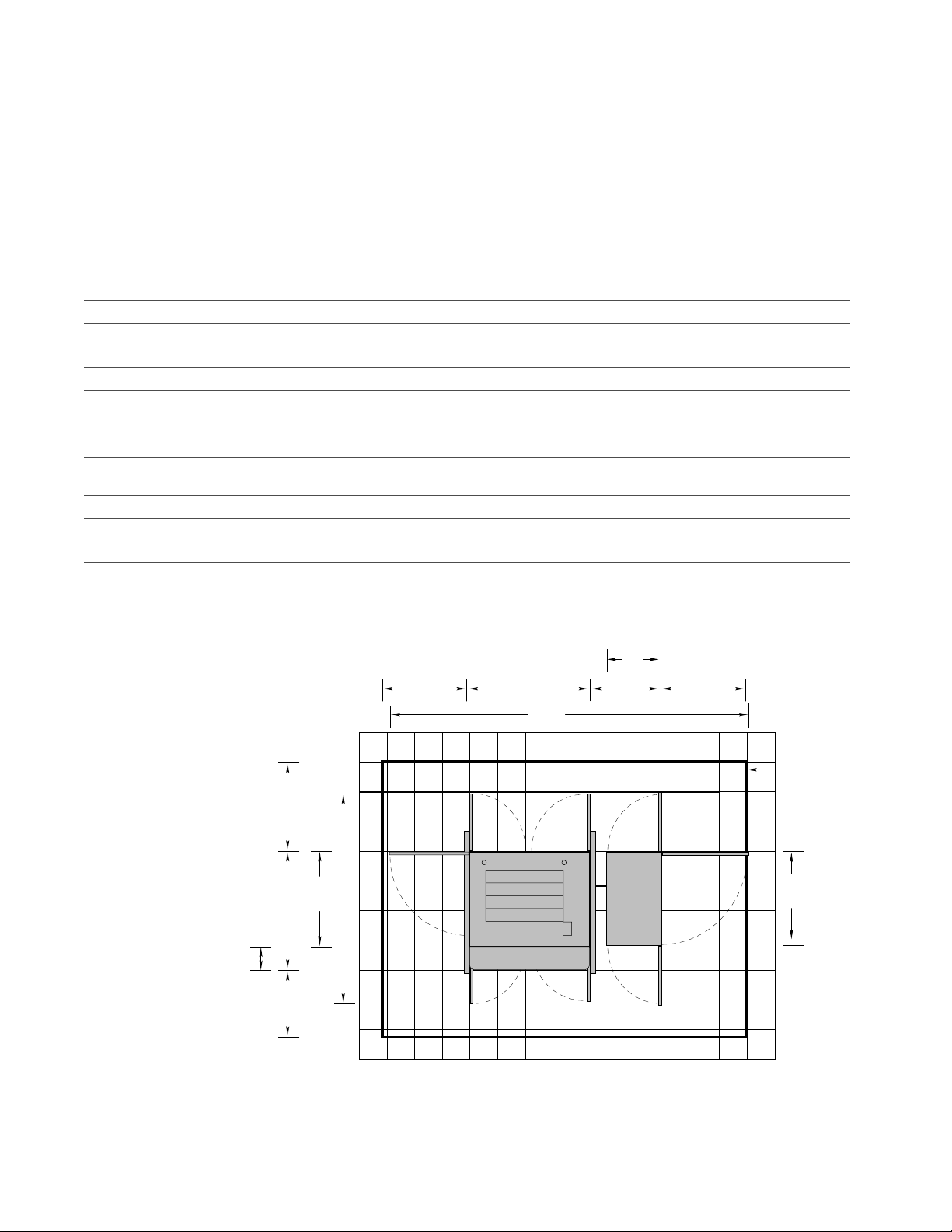
Z1884
Important:
The Z1884 requires a forklift to remove it from the crate.
Uncrated Dimensions Test Head Bay: 46.5 in. (118 cm) H x 49.5 in. (125 cm) D x 54.25 in. (138 cm) L
Power Bay: 35 in. (89 cm) H x 39.25 in. (99 cm) D x 24 in. (61 cm) L
Crate Dimensions Test Head Bay: 60 in. (152 cm) H x 64 in. (163 cm) D x 68 in. (173 cm) L
Power Bay: 46 in. (117 cm) H x 31 in. (79 cm) D x 46 in. (117 cm) L
Weight Crated (approximate) 1800 lb (817 kg)
Weight (approximate)
AC MAINS
AC MAINS Circuit Breaker
1400 lb (635 kg)
100–240VAC, 3.0kVA, 3-wire, 50–60Hz (range of 47–63Hz), single-phase
• 100–130VAC requires minimum of 25A breaker
• 200–240VAC requires minimum of 13A breaker
AC MAINS Receptacle
AC MAINS Cord Connector
Main AC Input Breaker
NEMA L5-30R
NEMA L5-30P
• 100–130 VAC requires 25A breaker PN 090-156-00
• 200–240 VAC requires 13A breaker PN 090-186-00
Vacuum Supply
41 CFM pump capacity recommended. 1 in. NPT male thread within 10 ft. of system.
Minimum vacuum level of 20 in. of mercury available to the system at all times.
Vacuum Pump Power
Vacuum Power Connectors
Line voltage of 190–460 VAC, 2.2 kVA, 30 Amp, 4-wire, 50 or 60Hz, 3-phase.
• Low Voltage 190–230 VAC uses 250 VAC, 20 Amp, 4-wire, NEMA L15-20P
• High Voltage 380–460 VAC uses 480 VAC, 20 Amp, 4-wire, NEMA L16-20P
Environmental Requirements Ambient temperature: 64˚–89˚F (18˚–32˚C)
Relative humidity: 20–70% non-condensing
Vacuum pump operating temperature range: 32˚–122˚F (0˚–50˚C)
Teradyne Provides
X
X
X
X
Floor Space Required
36"
49.5"
10.25
36"
(Table top extension)
93"
39.25"
236 cm
24"
40" 40"
54.25"
164.25"
442 cm
30"
36” service
36" service
access
access
boundary
39.25"
Z1800-Series Site Preparation Guide
6
Z1880 Plus: Z1880-1
Also see “PRISM-Z Option” on page 17 if applicable.
and Z1880-2
Uncrated Dimensions 32.5 in. (83 cm) H x 34.5 in. (88 cm) D x 48 in. (122 cm) L
Crate Dimensions 62 in. (158 cm) H x 45 in. (114 cm) D x 59 in. (150 cm) L
Weight Crated (approximate) Z1880-1: 800 lb (364 kg)
Weight (approximate) Z1880-1: 600 lb (273 kg)
AC MAINS 100–240VAC, 3.0kVA, 3-wire, 50–60Hz (range of 47–63Hz), single-phase X
AC MAINS Circuit Breaker • 100–130VAC requires minimum of 25A breaker
AC MAINS Receptacle NEMA L5-30R
AC MAINS Cord Connector NEMA L5-30P X
Main AC Input Breaker • 100–130 VAC requires 25A breaker PN 090-156-00
Vacuum Supply 41 CFM pump capacity recommended. 1 in. NPT male thread within 10 ft. of system.
Vacuum Pump Power Line voltage of 190–460 VAC, 2.2 kVA, 30 Amp, 4-wire, 50 or 60Hz, 3-phase.
Vacuum Power Connectors • Low Voltage 190–230 VAC uses 250 VAC, 20 Amp, 4-wire, NEMA L15-20P
Environmental Requirements Ambient temperature: 64˚–89˚F (18˚–32˚C)
Note:
Z1880-2: 1225 lb (556 kg
Z1880-2: 1000 lb (454 kg)
Teradyne Provides
• 200–240VAC requires minimum of 13A breaker
• 200–240 VAC requires 13A breaker PN 090-186-00
Minimum vacuum level of 20 in. of mercury available to the system at all times.
• High Voltage 380–460 VAC uses 480 VAC, 20 Amp, 4-wire, NEMA L16-20P
Relative humidity: 20–70% non-condensing
Vacuum pump operating temperature range: 32˚–122˚F (0˚–50˚C)
X
X
Floor Space Required
36"36"
34.5"
88 cm
36"
48"
122 cm
36"
36” service
36" service
access
access
boundary
Z1866
Uncrated Dimensions 28 in. (71 cm) H x 33.5 in. (85 cm) D x 73 in. (186 cm) L
Crate Dimensions 50 in. (127 cm) H x 43 in. (110 cm) D x 83 in. (211 cm) L
Weight Crated (approximate) 1250 lb (567 kg)
Weight (approximate) 1000 lb (454 kg)
Power Requirements Two AC service supply outlets
Teradyne Provides
AC MAINS 100–240VAC, 1.8kVA, 3-wire, 50–60Hz (range of 47–63Hz), single-phase X
AC MAINS Circuit Breaker • 100–130VAC requires minimum of 15A breaker
• 200–240VAC requires minimum of 7.5A breaker
AC MAINS Receptacle NEMA L5-30R
AC MAINS Cord Connector NEMA L5-30P X
Main AC Input Breaker • 100–130 VAC requires 15A breaker PN 087-11x-00
• 200–240 VAC requires 7.5A breaker PN 087-12x-00
Vacuum Supply 41 CFM pump capacity recommended. 1 in. NPT male thread within 10 ft. of system.
Minimum vacuum level of 20 in. of mercury available to the system at all times.
Vacuum Pump Power Line voltage of 190–460 VAC, 2.2 kVA, 30 Amp, 4-wire, 50 or 60Hz, 3-phase.
Vacuum Power Connectors • Low Voltage 190–230 VAC uses 250 VAC, 20 Amp, 4-wire, NEMA L15-20P
• High Voltage 380–460 VAC uses 480 VAC, 20 Amp, 4-wire, NEMA L16-20P
Environmental Requirements Ambient temperature: 64˚–89˚F (18˚–32˚C)
Relative humidity: 20–70% non-condensing
Vacuum pump operating temperature range: 32˚–122˚F (0˚–50˚C)
7
X
X
Floor Space Required
36"33.5"
36"
79.5"
199.38 cm
36" 73" 36"
130"
331.25 cm
36” service
36" service
access
access
boundary
Z1800-Series Site Preparation Guide
 Loading...