

Teradici PCoIP TER812002, PCoIP Management Console User Manual

PCoIP® Management Console
User Manual
TER0812002
Issue 5
2

PCoIP Management Console User Manual
Teradici Corporation
#101-4621 Canada Way, Burnaby, BC V5G 4X8 Canada
p +1 604 451 5800 f +1 604 451 5818
www.teradici.com
The information contained in this docum ent re presents the c urrent vie w of T eradici Cor poration a s of th e date of public ation.
Because Teradici must respond to ch anging m arket condi tions, i t should n ot be inte rpreted to be a commitm ent on the part of
Teradici, and Teradici cannot gu arantee t he accurac y of any informati on pres ented afte r the date of publicati on.
This document is for informational purposes only. TERADICI M AKES NO WARRANTIES , EXPRESS , IMPLIE D OR
STATUTORY, AS TO THE INFO RMATION IN T HIS DOC UMENT.
Complying with all applicable copyright la ws is the responsibili ty of the use r. Without li miting the rights under co pyright, no
part of this document may be re produce d, store d in or int roduce d into a retriev al syste m, or t ransmitted i n any form o r by an y
means (electronic, mechanical, photocopying, recording, or otherwise), or for any purpose, without the express written
permission of Teradici Corporation.
Teradici may have patents, patent applications, trade marks, copyrig hts, or other intell ectual propert y rights covering subj ect
matter in this document. Except as expressly provided in any written license agreement from Teradici, the furnishing of this
document does not give you any lic ense to these p atents, tradema rks, copyrig hts, or o ther intell ectual pr operty.
© 2011 Teradici Corporation. All rights reserved .
Teradici, PC-over-IP and PCoIP are registered trademarks of Teradici Corporation.
The names of actual companies and products mention ed herein may be the trademarks of thei r respective owner s.
TER0812002 Issue 5 2

Revision History
Version Date Description
1 April 3, 2009 Initial release
2 August 31, 2009 Updated for release 1.1 of the Management Console
3 March 01, 2010 Updated for release 1.2 of the Management Console
4 September 17, 2010 Updated for release 1.3.30 of the Management
PCoIP Management Console User Manual
Updated Management Console Limitations
(see Section 1.2)
Added Migrating to a New Version of the
Management Console (see Section 2.6)
Replaced PCoIPMC with MC
Added support for Internet Explorer
Console
Added Device Log Monitoring
Added support for Firmware Release 3.2
5 June 01, 2011 Updated for release 1.5 of the Management Console
Added AutoConfig
Added support for Firmware Release 3.3 and
3.4
Added OSD Logos to profiles
Added Firmware to profiles
Added Profile Application Status page
Changed term Portal to Zero Client
USB device bridging support
Added support for profile scheduling
Configurable DHCP Timeout options
TER0812002 Issue 5 3

PCoIP Management Console User Manual
Contents
REVISION HISTORY......................................................................................................3
CONTENTS ....................................................................................................................4
TABLE OF FIGURES .....................................................................................................7
TABLES..........................................................................................................................9
DEFINITIONS ...............................................................................................................10
INTRODUCTION........................................................................................................... 11
1 OVERVIEW.............................................................................................................12
1.1 PCoIP Deployment Components.....................................................................................................12
1.1.1 Managing PCoIP Devices.........................................................................................................12
1.1.2 DNS Server...............................................................................................................................13
1.2 Management Console Limitations....................................................................................................14
1.3 Management Console Concepts......................................................................................................14
1.3.1 Groups and Profiles..................................................................................................................14
1.3.2 Fixed Seating............................................................................................................................16
1.3.3 Device Discovery ......................................................................................................................16
1.3.4 AutoConfig ................................................................................................................................21
1.4 Management Console and Firmware Version Compatibility............................................................22
2 INSTALLATION AND SETUP ................................................................................ 24
2.1 Management Console Host System Requirements.........................................................................24
2.2 Contents of the Management Console package..............................................................................24
2.3 Installing the Management Console using VMware Player..............................................................25
2.4 Installing the Management Console into your existing VMware ESX™ server...............................25
2.5 Running the Management Console..................................................................................................25
2.6 Migrating to a New Version of the Management Console................................................................26
2.6.1 Potential Problems and Workarounds......................................................................................26
2.6.2 What Information is Imported....................................................................................................27
2.6.3 Database Migration Procedure.................................................................................................27
3 VIRTUAL MACHINE FEATURES...........................................................................29
TER0812002 Issue 5 4

PCoIP Management Console User Manual
3.1 Refresh Status..................................................................................................................................29
3.2 Set Web Interface Password............................................................................................................29
3.3 Change Hostname...........................................................................................................................29
3.4 Manage Networking.........................................................................................................................30
3.4.1 View Network Configuration......................................................................................................30
3.4.2 Configure IP Address................................................................................................................30
3.4.3 Configure DNS..........................................................................................................................31
3.5 Database Management....................................................................................................................31
3.5.1 Backup Database......................................................................................................................32
3.5.2 Restore Database.....................................................................................................................32
3.5.3 Delete Database.......................................................................................................................32
3.6 Change Time Zone...........................................................................................................................32
3.7 Restart Management Console Daemon...........................................................................................32
3.8 Halt Virtual Machine.........................................................................................................................33
4 WEB INTERFACE ..................................................................................................34
4.1 Accessing the Management Console Web User Interface..............................................................34
4.2 Device Management........................................................................................................................37
4.2.1 Device Discovery (optional) ......................................................................................................38
4.2.2 Legend......................................................................................................................................38
4.2.3 Query Devices and Update Database......................................................................................40
4.2.4 Filtering Devices........................................................................................................................40
4.2.5 Configure Device Group ...........................................................................................................41
4.2.6 Linking Devices.........................................................................................................................42
4.2.7 Access Device Web Page.........................................................................................................43
4.2.8 Summary Device Information....................................................................................................44
4.2.9 Device Details...........................................................................................................................45
4.3 Group Management.........................................................................................................................48
4.3.1 Manage Groups ........................................................................................................................49
4.3.2 View Profile Application Status.................................................................................................52
4.3.3 Manage AutoConfig..................................................................................................................53
4.3.4 View AutoConfig Status............................................................................................................55
4.4 Profile Management.........................................................................................................................56
4.4.1 Create a Profile.........................................................................................................................56
4.4.2 Duplicate a Profile.....................................................................................................................57
4.4.3 Delete a Profile..........................................................................................................................57
4.4.4 Modify Profile Name & Description...........................................................................................57
4.4.5 Modify Profile Properties...........................................................................................................57
4.5 Power Management.........................................................................................................................60
4.5.1 Sending Reset and Power off Commands................................................................................61
4.5.2 Power Management Status.......................................................................................................62
4.6 Update Firmware..............................................................................................................................63
4.6.1 Import Firmware........................................................................................................................64
TER0812002 Issue 5 5

PCoIP Management Console User Manual
4.6.2 Update Device Firmware ..........................................................................................................64
4.6.3 View Status...............................................................................................................................66
4.7 Device Log Monitoring......................................................................................................................67
4.7.1 Device Tree...............................................................................................................................67
4.7.2 Logging Controls.......................................................................................................................68
4.7.3 Status........................................................................................................................................68
4.8 Manage Settings ..............................................................................................................................68
4.8.1 Database Management.............................................................................................................69
4.8.2 Environment Settings................................................................................................................70
4.9 Site Status........................................................................................................................................70
4.10 Online Help...................................................................................................................................72
5 GETTING STARTED ..............................................................................................73
5.1 Start the Management Console .......................................................................................................73
5.2 Discover Devices..............................................................................................................................73
5.3 Adding Devices to a Group..............................................................................................................73
5.4 Peering Devices...............................................................................................................................74
5.5 Next Steps........................................................................................................................................75
TER0812002 Issue 5 6

Table of Figures
Figure 1-1: PCoIP Deployment Components ...................................................................12
Figure 1-2: Management Console Groups and Profiles...................................................15
Figure 1-3: DNS Service Configuration Menu ..................................................................17
Figure 1-4: DNS Service Location (SRV) Dialog Box.......................................................18
Figure 1-5: Management Console Manual Device Discovery Feature.............................21
Figure 2-1: MC VM Console in VMware Player................................................................26
Figure 3-1: Management Console VM Console................................................................29
Figure 3-2: Manage MC VM Console Network Settings...................................................30
Figure 3-3: Manage MC VM Console Database...............................................................31
Figure 4-1: Web Interface Security Warning in Firefox.....................................................35
Figure 4-2: Web Interface Security Warning in Internet Explorer.....................................35
Figure 4-3: Management Console License Agreement....................................................36
Figure 4-4: Web Interface Login .......................................................................................36
PCoIP Management Console User Manual
Figure 4-5: Home Web Page............................................................................................37
Figure 4-6: Device Management Web Page.....................................................................38
Figure 4-7: Device Management Legend Box..................................................................39
Figure 4-8: Adding Devices to a Group.............................................................................42
Figure 4-9: Peering a Pair of Devices...............................................................................43
Figure 4-10: Summary Device Information Dialog Box.....................................................44
Figure 4-11: Edit Device Name Using Summary Device Information Dialog Box............44
Figure 4-12: Zero Client Device Details Web Page..........................................................46
Figure 4-13: Device Event Log Web Page .......................................................................48
Figure 4-14: Group Management Web Page....................................................................49
Figure 4-15: Apply Profile reboot behavior options...........................................................51
Figure 4-16: Apply Profile date/time picker.......................................................................52
Figure 4-17: View Profile Application Status Web Page...................................................53
Figure 4-18: Manage AutoConfig Web Page....................................................................55
Figure 4-19: View AutoConfig Status Web Page..............................................................56
Figure 4-20: Profile Management Web Page ...................................................................56
Figure 4-21: Profile Management – Set Properties Web Page ........................................58
Figure 4-22: Bandwidth Configuration Settings Dialog Box..............................................59
Figure 4-23: Add OSD Logo property...............................................................................59
Figure 4-24: Link to Imported Firmware property .............................................................60
Figure 4-25: Power Management Web Page ...................................................................60
Figure 4-26: Send Device State Change Command Web Page ......................................61
TER0812002 Issue 5 7

PCoIP Management Console User Manual
Figure 4-27: Schedule Device State Change Command Web Page................................62
Figure 4-28: Power Management Status Web Page........................................................63
Figure 4-29: Update Firmware Web Page........................................................................64
Figure 4-30: Initial Update Devices Web Page.................................................................65
Figure 4-31: Second Update Devices Web Page.............................................................66
Figure 4-32: Firmware Update Status Web Page.............................................................66
Figure 4-33: Device Log Monitoring Web Page................................................................67
Figure 4-34: Settings Web Page.......................................................................................69
Figure 4-35: Database Management Web Page..............................................................69
Figure 4-36: Home Web Page..........................................................................................71
Figure 4-37: Help Web Page ............................................................................................72
Figure 5-1: Adding Devices to a Group.............................................................................74
Figure 5-2: Peering a Pair of Devices...............................................................................75
TER0812002 Issue 5 8

Tables
PCoIP Management Console User Manual
Table 2-1: Potential Problems Associated with Upgrading the MC 26
Table 4-1: Example AutoConfig rules 54
Table 4-2: Example AutoConfig rule application 54
TER0812002 Issue 5 9

PCoIP Management Console User Manual
Definitions
DHCP Dynamic Host Configuration Protocol
DNS Domain Name System
DNS SRV Domain Name System Service Record
FQDN Fully Qualified Domain Name
MC PCoIP Management Console
OS Operating System
OSD On Screen Display
®
PC-over-IP
PCoIP
PCoIP Host Host side of PCoIP system
PCoIP Zero Client Desktop or client side of PC-over-IP® system. For example, PCoIP Portal or
SLP Service Location Protocol
URL Uniform Resource Locator, Web site address
Personal Computer over Internet Protocol
®
Personal Computer over Internet Protocol (PC-over-IP®)
PCoIP Integrated Display.
VM VMware Virtual Machine
Zero Client See PCoIP Zero Client
TER0812002 Issue 5 10

Introduction
The Teradici PCoIP Management Console (MC) enables administrators to centrally
manage a PCoIP deployment. The MC is packaged as a VMware® virtual machine (VM)
and runs on VMware Player. A web browser is used to access and control the MC.
Administrators can use the MC to do the following:
• Access and update the configuration of all PCoIP devices
• Apply the same configuration data to groups of devices
• Update device firmware
• Reset devices
• Control the power state of host devices
• View status information
• Manage the monitoring of device event logs
• Automatically configure newly discovered devices with a profile (optionally with
This document describes how to install and set up the PCoIP Management Console. It
also describes the features of the tool. More detailed information describing the individual
PCoIP device configuration fields is available in the PCoIP Administrative Interface User
Manual (TER0606004).
PCoIP Management Console User Manual
firmware and OSD logo) based on device password and IP address values.
This document is broken into the following sections:
• Section 1 provides a description of the components found in a PCoIP deployment
along with some important concepts associated with the MC
• Section 2 describes how to install and set up the MC and migrate from an old
version of the tool to a new version
• Section 3 details the features of the MC virtual machine
• Section 4 discusses the web interface of the MC, this is the primary mechanism
used by administrators to manage the PCoIP devices
• Section 5 describes how to use the MC to perform some basic tasks
Note: First time users of the MC that want to begin using the tool right away should
review section 5. This section provides information on how to start the MC, log into the
web interface, discover some devices and link a pair of Host and Zero Client devices.
After this is done the user will be able to establish a PCoIP session between the linked
Host and Zero Client devices. This section also includes recommendations the user
should follow to become familiar with the major capabilities of the MC.
TER0812002 Issue 5 11
PCoIP Management Console User Manual
1 Overview
This section describes the components found in a typical PCoIP deployment. It describes
some important concepts that help the user understand how to use the MC to manage
the PCoIP devices in a deployment.
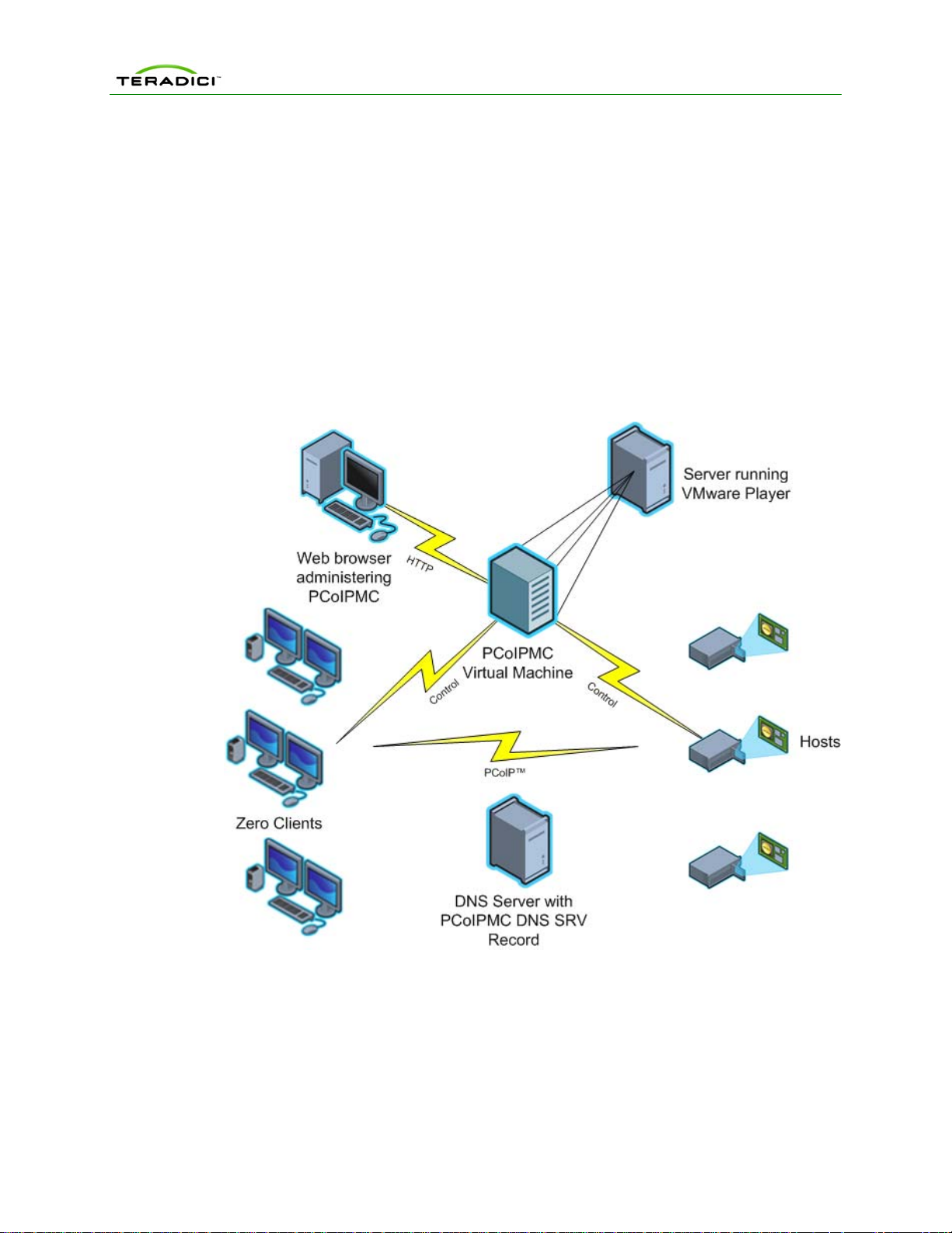
1.1 PCoIP Deployment Components
Figure 1-1 shows the recommended components found in a PCoIP deployment where
individual Host and Zero Client devices are statically grouped together (peered). The
PCoIP Management Console, used for peering and configuration, is shown. The figure
does not show a connection broker, which is required when Hosts are dynamically
assigned to Zero Clients as users log in.
Figure 1-1: PCoIP Deployment Components
1.1.1 Managing PCoIP Devices
A PCoIP deployment is made up of one or more PCoIP Host and Zero Client devices.
Each device has multiple configuration settings that can be accessed and controlled
using the following mechanisms:
Device Web Interface
Each device can be configured individually via web-based administration interface.
TER0812002 Issue 5 12

PCoIP Management Console User Manual
However, users should avoid changing the configuration settings th rough the device web
interface, especially as the deployment grows. Instead, users are encouraged to use the
MC; this ensures that all PCoIP devices are configured uniformly and that the MC
database accurately reflects the device configuration settings. Refer to the PCoIP
Administrative Interface User Manual (TER0606004) for information on the web interface.
PCoIP Management Console
The Teradici PCoIP Management Console (MC) enables administrators to centrally
manage a PCoIP deployment. Administrators can use the MC to do the following:
• Access and update the configuration of all PCoIP devices
• Apply the same configuration settings to groups of devices
• Update device firmware
• Reset devices
• Control the power state of Host devices that support power management
• View status information
• Manage the monitoring of device event logs
• Automatically configure newly discovered Zero Clients with a profile (optionally
with firmware and OSD logo) based on device password and IP address values.
The MC is packaged as a VMware virtual machine (VM) and runs on VMware Player.
This allows users to install and run the MC on any host machine that can run VMware
Player.
A web browser is used to access and control the MC.
The MC must be connected to the same network the PCoIP devices are connected to.
This is required to allow the tool to communicate with the PCoIP devices.
Connection Broker
A Connection Broker is an optional component that allows an administrator to manage
user access to computing resources. This component is not shown in Figure 1-1. In a
PCoIP deployment, a connection broker is used to assign connections between PCoIP
Host and Zero Client devices and/or RDP sessions between terminal servers and PCoIP
Zero Clients. Deployments having one or more of the following requirements must install
a connection broker:
• Hosts are dynamically assigned to Zero Clients based on the login credentials of
the person using the Zero Client.
• Zero Clients establish RDP sessions with terminal servers.
1.1.2 DNS Server
Figure 1-1 shows a DNS Server with the MC DNS SRV record. This component is
optional, but highly recommended. The MC must discover the PCoIP Host and Zero
Client devices, and the MC DNS SRV record facilitates automatic device discovery. A
Connection Broker DNS SRV record can also be installed on the DNS Server. PCoIP
devices use this record to notify the connection broker of their existence.
When a PCoIP device boots it reads these records, which contain the addresses of the
MC and/or connection broker. After reading the records, the device sends messages to
the MC and/or connection broker notifying them of the devices existence. This ensures
the MC and/or connection broker is aware of all the devices in the deployment as they
are powered on.
The MC DNS SRV record is not required when one of the following conditions is true:
TER0812002 Issue 5 13

PCoIP Management Console User Manual
• All PCoIP devices in a deployment reside on the same network subnet as the
MC. In this situation the MC can find the devices using SLP discovery. All
devices must set the Enable SLP Discovery configuration setting equal to True.
• The PCoIP MC DNS-Based Discovery Prefix setting of all devices is configured
to equal the hostname prefix of the MC. This setting can only be accessed using
the MC. It is not accessible through the device web interface or Zero Client OSD
interface. Section 1.3.3.2 describes how PCoIP devices use the PCoIP MC DNSBased Discovery Prefix to contact the MC along with the system requirements
that must be met to use this option.
If none of the previous conditions are true users should include a DNS Server in their
system and install the MC DNS SRV record. Section 1.3.3.1 describes how to install this
record.
1.2 Management Console Limitations
This section describes some limitations of the MC.
• All PCoIP devices managed by the MC must be loaded with firmware release
0.19 or greater. The MC cannot discover devices loaded with older firmware
releases. New firmware must be uploaded and activated on devices running
firmware releases less than or equal to 0.18. This is done through the device web
interface. Refer to the PCoIP Administrative Interface User Manual
(TER0606004) for information on how to do this.
• The current release of the MC is only compatible with versions 3.0 and higher of
the Firefox web browser and versions 7 and 8 of the Internet Explorer web
browser. Support for additional browsers will be included in future releases of the
MC.
• The current release of the MC only supports configuring Zero Clients to establish
PCoIP sessions. It does not support configuring RDP sessions. If this is required
a connection broker should be installed in the deployment.
• The MC supports linking PCoIP Host and Zero Client devices in fixed seating
mode where the same Zero Client always connects to the same Host. If
dynamically assigning Zero Clients to Hosts is required, the deployment must
include a connection broker.
• The MC supports managing up to 2000 PCoIP devices. The tool may be capable
of supporting more than 2000 devices, but the current version has been tested
with a maximum of 2000 devices. Support for more than 2000 devices will be
included in a future release of the tool. Deployments with more than 2000
devices should contact their PCoIP equipment supplier for guidance on how to
manage more than 2000 devices.
1.3 Management Console Concepts
This section describes some key concepts users should be aware of before using the
MC.
1.3.1 Groups and Profiles
The MC manages the PCoIP devices using two important concepts (groups and profiles).
A profile is a set of device configuration settings and a group is a set of one or more
devices with a single profile. Figure 1-2 shows one way in which groups of Host devices
TER0812002 Issue 5 14
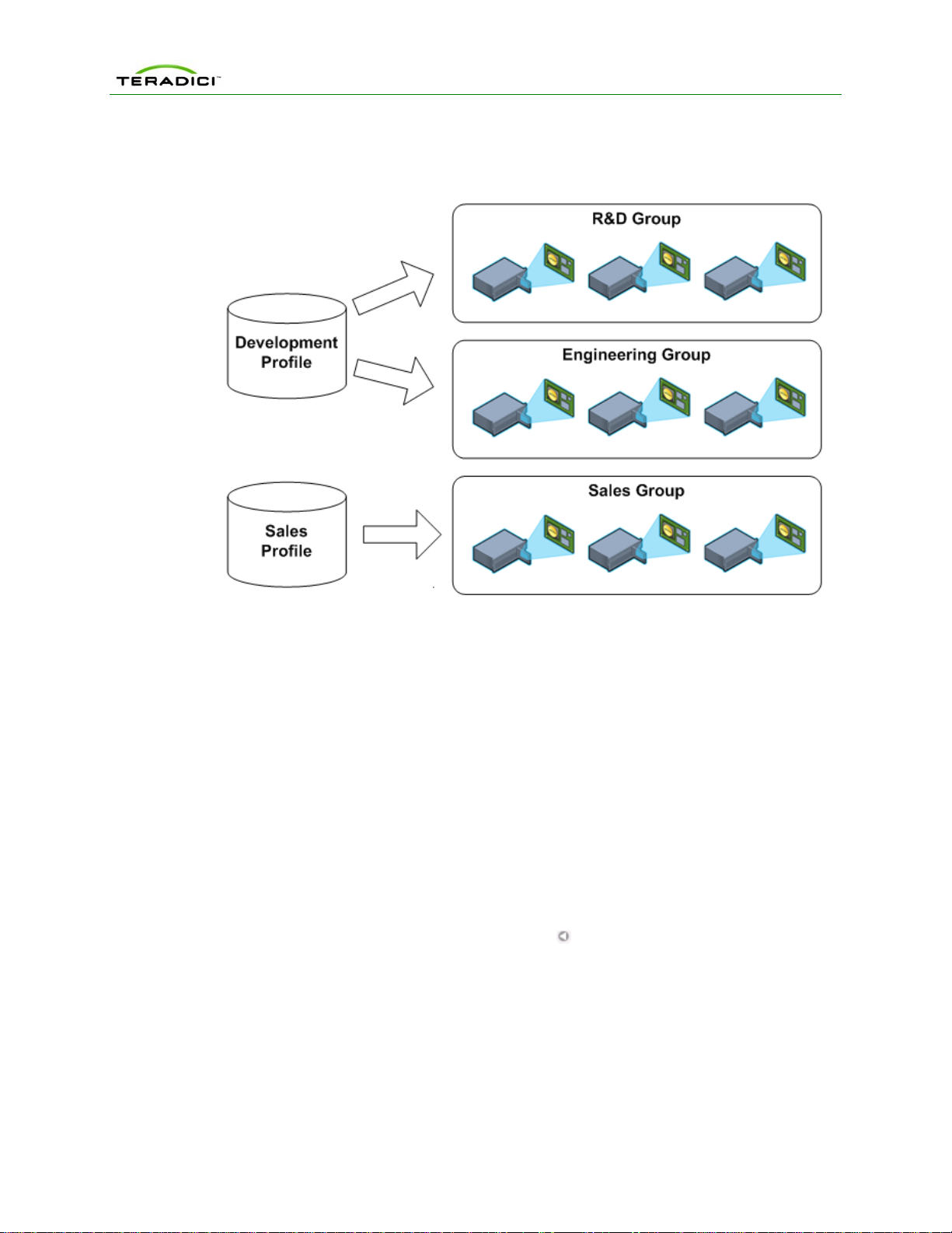
PCoIP Management Console User Manual
could be related to profiles. The figure shows three groups of devices. Two of the groups
share the same profile. In this situation all configuration settings defined in the
Development Profile will be written to the devices in the R&D and Engineering groups.
Figure 1-2: Management Console Groups and Profiles
Below are some important rules regarding groups and profiles.
• Each group has one and only one profile associated with it.
• The same profile can be associated with multiple groups.
• All configuration settings in a profile are written to all devices in a group when the
profile is applied to the group.
• A profile can contain values for every configuration parameter but this is not
required. A profile can be defined that contains a subset of the configuration
parameters.
• If the firmware on a device is updated when a profile is applied the profile
settings will be written to the device after the new firmware is activated.
• Profiles contain settings that allow users to specify whether a device’s firmware is
updated based on the version of the firmware running on the device.
• When profile settings are written to devices the settings might not take effect
immediately. Some settings are activated after a device is reset. Profile settings
that require a reset are preceded by the
symbol within the MC Profile Set
Properties and Device Details web pages. Users should consider resetting all
devices in the deployment after updating device configuration settings.
• When devices are added to a group and the group profile has not changed, the
profile should be applied to the newly added devices and not the entire group.
This will minimize the number of device resets.
TER0812002 Issue 5 15

PCoIP Management Console User Manual
1.3.2 Fixed Seating
The MC allows an administrator to link individual Host and Zero Client devices so that
each Zero Client always establishes a connection to the same Host. This relationship is
called fixed seating. If a PCoIP deployment requires the ability to dynamically assign
Hosts to Zero Clients when users login the administrator must install a connection bro ke r.
The MC does not support dynamically assigning Hosts to Zero Clients.
1.3.3 Device Discovery
All PCoIP devices managed by the MC must be discovered by the MC. The MC supports
discovering devices in a deployment using one or more discovery mechanisms.
1. It is recommended to install a MC DNS SRV record. Section 1.3.3.1 describes how to
install a DNS SRV record.
Note it may not be possible to install a DNS SRV record because the network does
not include a DNS server or multiple instances of the MC will be installed on the same
network managing subsets of the PCoIP devices.
2. If a DNS SRV record cannot be installed users may be able to configure the d evices
to automatically notify the MC of their existence. PCoIP devices support a
configuration setting called the PCoIP MC DNS-Based Discovery Prefix. Section
1.3.3.2 describes how this feature works and the deployment requirements associated
with using this discovery method.
Note: The PCoIP MC DNS-Based Discovery Prefix setting can only be accessed
using the MC. It is not accessible through the device web interface or Zero Client OSD
interface.
3. If a DNS SRV record cannot be installed and the deployment cannot use the PCoIP
MC DNS-Based Discovery Prefix configuration setting then the final automated device
discovery option available is SLP discovery. This device discovery method imposes a
restriction that limits its usefulness. To use this feature all PCoIP devices and the MC
must reside on the same network subnet.
4. If a deployment cannot support any of the previous device discovery options then the
administrator can use the MC to configure devices. The MC supports a Manual
Discovery feature that allows the MC to find devices. This feature is described in
section 1.3.3.3. Below are some shortcomings associated with this approach:
• If a device has enabled DHCP, the MC will lose contact with a device if its IP
address changes. The administrator would need to perform another manual
discovery search to find devices that were assigned new IP addresses.
1.3.3.1 DNS Servi ce Record Discover y
When DNS SRV record discovery is used, the PCoIP devices advertise themselves to
the MC. All devices that use the DNS server will be able to find the MC. If DNS-SRV
discovery is not enabled, the MC must seek out and find devices using methods that are
often subject to limitations, such as being unable to search more than its local subnet.
The system requirements for DNS SRV discovery are as follows:
• The deployment must have a DNS Server in the network
• Two DNS records must be installed on the DNS server
o An A record (name record) for the MC
o A SRV record (service record) created following the steps below
TER0812002 Issue 5 16
PCoIP Management Console User Manual
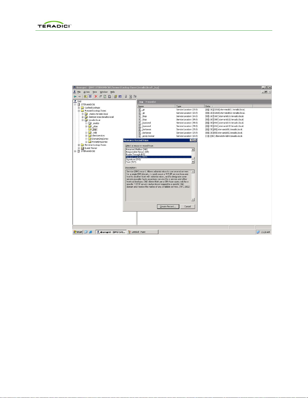
Add the MC DNS SRV Record to the DNS Server
To add the MC DNS SRV record to DNS Server in Windows 2003 Server, perform the
following steps:
1. Enter DNS service configuration on domain controller.
2. Navigate to local domain and _tcp entry.
Figure 1-3: DNS Service Configuration Menu
3. Right click and select “Other New Records …”
4. Select “Service Location (SRV )”.
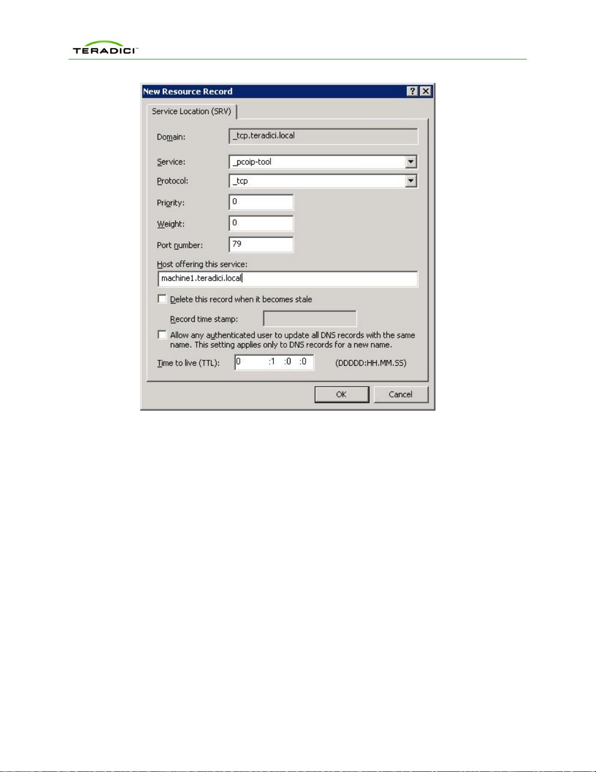
5. Fill in the entries as shown in Figure 1-4 and enter the hostname where the MC is
installed under “Host offering this service”. The “Port Number” in the configuration is
not used by the PCoIP devices. However, it may be set to 50000 to reflect the
listening port of the CMI server.
TER0812002 Issue 5 17
PCoIP Management Console User Manual
Figure 1-4: DNS Service Location (SRV) Dialog Box
1.3.3.2 PCoIP Management Console DNS-Based Discover y Prefix
Each PCoIP device reads the PCoIP MC DNS-Based Discovery Prefix setting when it
boots. If this setting is non-blank then the device attempts to contact the MC by
combining the string stored in this setting with variations of the domain name hierarchy.
System Requirements
The system requirements for MC DNS-Based Discovery are as follows:
• The PCoIP devices and MC must be located within the same domain name
hierarchy tree (e.g. if a PCoIP device is located in the domain
sales.europe.companyname.com, then the MC’s domain name can be any one
of: sales.europe.companyname.com, europe.companyname.com, or
companyname.com)
• The PCoIP devices must enable DHCP in order to get the domain name and
hostname (to get DHCP options 15 and 12 respectively)
• The DHCP server must support either DHCP options 12 (hostname), 15 (domain
name), or both. Refer to RFC2132. If the DHCP server only supports DHCP
options 12, the hostname string must contain the domain name.
• All PCoIP devices managed by a specific MC must have the PCoIP MC DNS-
Based Discovery Prefix setting equal to the MC’s hostname prefix (e.g. if the
MC’s FQDN is pcoip_mc1.europe.companyname.com, then the field must equal
pcoip_mc1).
TER0812002 Issue 5 18

PCoIP Management Console User Manual
Algorithm
Each time a PCoIP device boots it executes the MC DNS-Based Discovery algorithm if
the PCoIP MC DNS-Based Discovery Prefix setting is non-blank. The algorithm uses the
setting and the domain name hierarchy to search for a MC.
The PCoIP device obtains the domain name string from the DHCP server using DHCP
options 15. Since some DHCP servers may not have DHCP options 15 implemented, the
device also obtains the host name using DHCP options 12 (assumed to include the
domain name).
Since the device and MC may not be on the same domain (but must be within the same
hierarchy), the device composes many FQDN variations using the results from DHCP
options 12 and 15. With each FQDN variation, the hostname prefix remains constant
however the domain hierarchy level changes.
The device sequentially attempts each FQDN possibility until a hit is found, at which point
the device completes DNS-based discovery. The algorithm may take several minutes in
order to find the correct FQDN address of the MC (depends on the number of levels in
the domain name hierarchy and the MC load).
In detail, the algorithm works as follows. The device uses domain name variations based
on the DHCP options 15 string. For each FQDN possibility, the device attempts to
transmit a status message to the MC at the FQDN. Upon transmission timeout, the
device composes the next FQDN variation by proceeding one level up the domain
hierarchy. The last domain name attempted has a single dot in the string. After
exhausting the FQDN possibilities (based on the DHCP options 15 string), the device
delays for 5 minutes and then uses hostname variations based on the DHCP options 12
string. After failing to contact a MC using the DHCP options 12 string, the device delays 5
minutes and then cycles back to using DHCP options 15. The device continues this
process until a MC is contacted.
Example
In the example below, the DHCP options 15 returns sales.europe.companyname.com.
DHCP options 12 returns hostmachine1.sales.europe.companyname.com. Note that the
DHCP server may return no value for either option. The MC configured the PCoIP MC
DNS-Based Discovery Prefix in the device to equal pcoip_mc1.
The device creates the following FQDNs and sequentially attempts contact with the MC:
(attempt #1) pcoip_mc1.sales.europe.companyname.com
(attempt #2) pcoip_mc1.europe.companyname.com
(attempt #3) pcoip_mc1.companyname.com
<device delays for 5 minutes>
(attempt #4) pcoip_mc1.hostmachine1.sales.europe.comp anyname.com
(attempt #5) pcoip_mc1.sales.europe.companyname.com
(attempt #6) pcoip_mc1.europe.companyname.com
(attempt #7) pcoip_mc1.companyname.com
<device delays for 5 minutes>
(attempt #8) pcoip_mc1.sales.europe.companyname.com (repeat 1-7)
TER0812002 Issue 5 19

PCoIP Management Console User Manual
...
Attempts 1 to 3 use the domain name from DHCP options 15 string. Failing to contact
the MC, the device uses the DHCP options 12 string for attempts 4 to 7. Failing
transmissions for attempt 4 to 7, the device cycles back to using DHCP options 15.
1.3.3.3 Manual Device Discover y
Manual device discovery is not an automated discovery mechanism. This mechanism
supports discovering devices that are powered on and connected to the network when
the MC is commanded to discover devices.
MC supports manually discovering devices at a specific IP address, in a range of IP
addresses or at an FQDN. This option is useful for users that want to quickly begin using
the MC. It is also useful when a deployment uses the PCoIP MC DNS-Based Discovery
Prefix configuration setting described in section 1.3.3.2. In this situation the administrator
can discover devices using this feature and configure the PCoIP MC DNS-Based
Discovery Prefix setting of each device so the devices contact the MC each time they
boot.
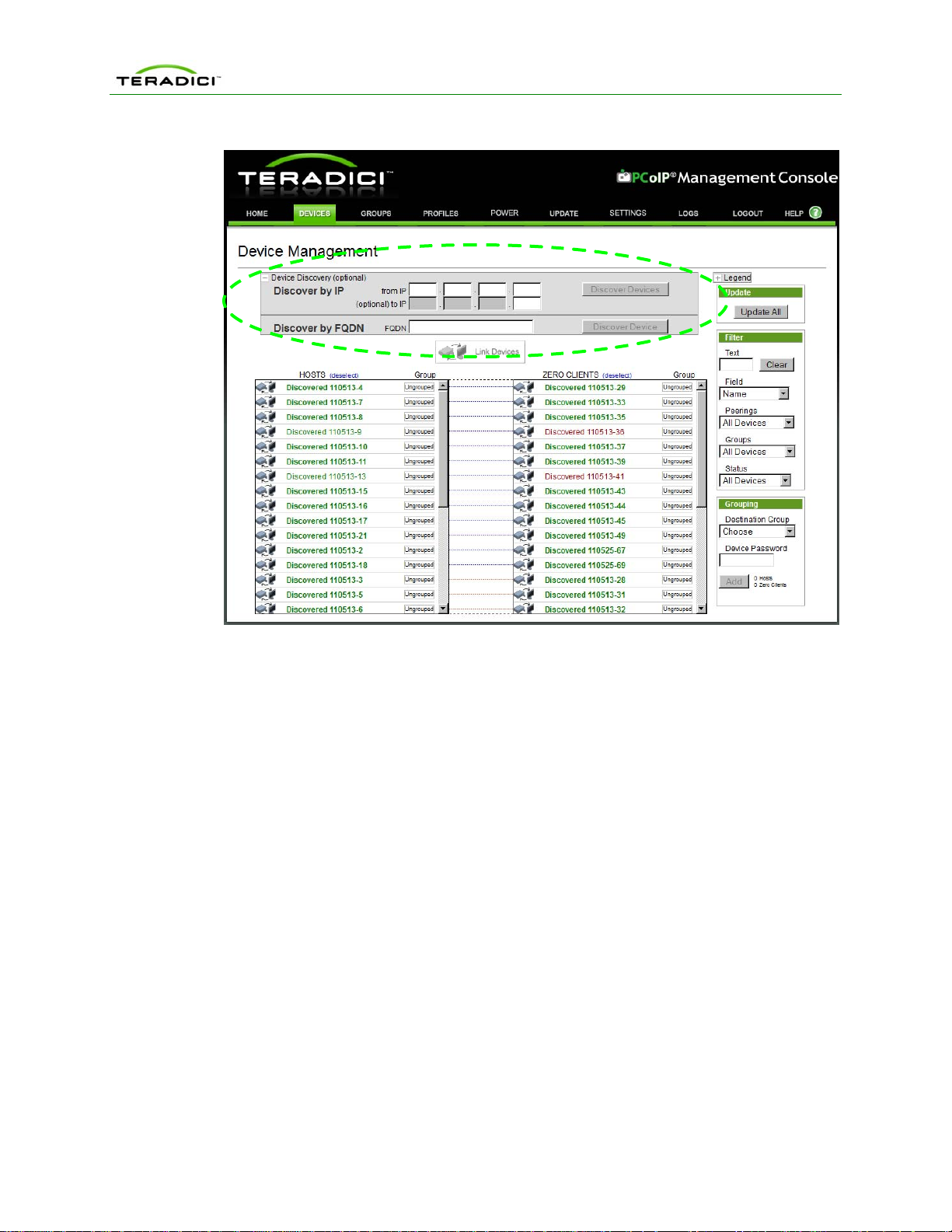
Figure 1-5 shows the Management Console Device Management web page with the
Device Discovery feature highlighted.
• When the IP address of a device is known and the device has not been
discovered enter the address in the from IP field and select Discover Devices.
• When a device is on a specific subnet but its IP address is not known the MC can
be commanded to discover all devices in a range of IP addresses using both the
from IP and (optional) to IP fields. After the address range has been specified
select Discover Devices. Note that this process can take a few minutes to
complete depending on the number of addresses searched. A status bar is
displayed while the tool discovers devices.
• When the FQDN of a device is known and the device has not been discovered
enter the FQDN in the FQDN field and select Discover Devices.
TER0812002 Issue 5 20
PCoIP Management Console User Manual
Figure 1-5: Management Console Manual Device Discovery Feature
1.3.4 AutoConfig
Any PCoIP Zero Clients newly discovered by the MC may be automatically added to a
group and have that group’s profile applied without user interaction. One or more
AutoConfig rules can be created that allow one group to have one or more criteria
defined. The MC supports the following criteria to decide how Zero Clients are
automatically assigned to groups using AutoConfig:
• Each group can have an optional AutoConfig rule associated with it
• Rules are sets of optional password settings and optional IP address ranges as
described here:
The order of events that occurs when a Zero Client has been discovered is:
o No Password: Add discovered Zero Clients to this group if they have no
password configured.
o Password: Add discovered Zero Clients to this group if they have the
identical password configured for the criteria.
o IP address range: Add discovered Zero Clients to this group if the IP
address falls within the range configured by this criteria. Not specifying
an IP address range will add all Zero Clients that match the password
criteria.
1. Device is listed in the AutoConfig status table with a status of Not Started
2. Zero Client IP address and password are compared against all AutoConfig rules.
3. If a match is found then the Zero Client is added to that group
TER0812002 Issue 5 21

PCoIP Management Console User Manual
4. If the group‘s profile contains a firmware rule then the firmware is applied if it
passes the criteria and the device is rebooted.
5. The remainder of the profile‘s properties are now applied to the device.
6. After applying the profile‘s OSD logo and properties the Zero Client will be
rebooted.
1.4 Management Console and Firmware Version Compatibility
MC Version Supports FW Versions Fully Configures FW Versions
1.0.26, 1.0.28 0.19-current 0.19-1.10
1.1.20 0.19-current 0.19-2.2
Added the ability to:
• ConfigureViewConnection
Serveraddress
• ConfigureViewConnection
Serverport
• Enable/disableViewConnection
ServerSSL
• Enable/disableViewConnection
ServerAutoConnect
• Configuredevicebandwidth
floor
1.2.20 0.19-current 0.19-3.1.0
Added the ability to:
• Enable/disableSNMPserver
• Enable/disablehostdriver
function
• Configuresessionencryption
modes
• ChoosetheKoreankeyboard
layout
1.3.30 0.19-current 0.19-3.2.0
Added the ability to:
• Danish,Finnish,Norwegian,
Swedish,Turkish,Dutch,Polish,
Belgian,RussianandLithuanian
KeyboardLayouts
• AdvancedVMwareViewSettings
• VMwareViewKioskMode
• Enable/disablePeerLossOverlay
TER0812002 Issue 5 22

PCoIP Management Console User Manual
1.4.30, 1.4.40 0.19-current 0.19-3.3.0
Added the ability to:
• ConfigureViewdesktopnameto
select
• Enable/disableZeroClientweb
interface
• SelectivedisplayofZeroClient
On‐ScreenDisplaymenuentries
• VMwareViewConnectionServer
addresscachebehaviourand
content
• ChoosetheEstonian,Hungarian,
LatvianandSerbiankeyboard
layouts
• ConfigureVMwareViewauto‐
logon
1.5.20 0.19-current 0.19-3.4.0
Added the ability to:
• Configuresyslog
• ConfigurestaticIPaddress
fallback
• ChoosetheCzech,Romanianand
Sloveniankeyboardlayouts
• ConfiguretheUSBbridging
overridetable
TER0812002 Issue 5 23
 Loading...