

Teradici t310, PCoIP Management Console User Manual

PCoIP® Management Console
User Manual
TER0812002
Issue 9

PCoIP Management Console User Manual
Teradici C o rp or at i on
#101-4621 Canada Way, Burnaby, BC V5G 4X8 Canada
p +1 604 451 5800 f +1 604 451 5818
www.teradici.com
The information contained in this document represents the current view of Teradici Corporation as of the date
of publication. Bec a us e T e rad ic i m ust res po n d t o c h an gi ng m a rk et c o ndi t i ons, i t sh o ul d n ot b e i nt er pr et e d t o be
a commitm ent on the pa rt of Te rad ici , and Te ra dic i cann ot gu aran tee the acc ur ac y of any inf o rmat ion
present e d af t er t he d at e of p ublication.
This doc um e nt is f or i nf o rm at i ona l p ur pos es onl y. TE RA DICI MAKES NO W ARR AN TI ES, EXPRESS, I MP LI E D
OR STATUTORY, AS TO THE INFORMATION IN THIS DOCUMENT.
Complying with all applicable copyright laws is the responsibility of the user. Without limiting the rights un der
copyri ght, no part of thi s doc umen t may b e repr oduc ed, sto red i n or int ro duce d into a r etri ev al s ystem , or
transmitted in any form or by any means (electronic, mechanical, photocopying, recording, or otherwise), or for
any purpose, without the express written permission of Teradici Corporation.
Teradici may have patents, patent applications, trademarks, copyrights, or other intellectual property rights
covering subject matter in this document. Except as expressly provided in any written license ag re em ent from
Teradici , t he fu rnish ing of this doc umen t do es not give y ou any lice ns e to thes e pat en ts, t radem ark s,
copyrights, or other intellectual property. Visit http://www.teradici.com/teradici/pat.php
for more information.
© 2012 Teradici Corporation. All rights reserved.
Teradici, PC-over-IP, and PCoIP are registered trademarks of Teradici Corporation in the United St at es and /o r
other countries. The names of actu al com pa nies an d pr oducts mentioned herein may be the trademarks of
their res pec tiv e own ers.
TER0812002 Issue 9 3

PCoIP Management Console User Manual
Revision History
Version Date Description
9 August 13, 2012 Updated for release 1.8 of the Management Console
• Added support for Firmware Release 4.0.0
• Added support for Firmware Release 4.0.1
• Added support for Tera2 devices
• Added DHCP Option Matching in AutoConfig
• Added Persistent AutoConfig
• Added Display Topology Configuration to profiles
• Enhanced Login process
8 January 20, 2012 Updated for release 1.7.1 of the Management Console
• Added support for Firmware Release 3.5.1
7 December 02, 2011 Updated for release 1.7 of the Management Console
• Added support for Firmware Release 3.5
• Added Certificates to profiles
• Added Session Connection Type
6 October 01, 2011 Updated for release 1.6 of the Management Console
• Added Remote Power Down
• Added Import and Export to profiles
• Added Retry and Apply AutoConfig
• Added Manage Device Naming
• Added Delete button to Device Management
5 June 01, 2011 Updated for release 1.5 of the Management Console
• Added AutoConfig
• Added support for Firmware Release 3.3 and 3.4
• Added OSD Logos to profiles
• Added Firmware to profiles
• Added Profile Application Status page
• Changed term Portal to zero client
• USB device bridging support
• Added support for profile scheduling
• Configurable DHCP Timeout options
4 September 17, 2010 Updated for release 1.3.30 of the Management Console
• Added Device Log Monitoring
• Added support for Firmware Release 3.2
3 March 01, 2010 Updated for release 1.2 of the Management Console
• Replaced PCoIPMC with MC
• Added support for Internet Explorer
2 August 31, 2009 Updated for release 1.1 of the Management Console
• Updated Management Console Limitations (see Section
1.2)
• Added Migrating to a New Version of the Management
Console (see Section 2.6)
TER0812002 Issue 9 4

PCoIP Management Console User Manual
1 April 3, 2009 Initial release
TER0812002 Issue 9 5

PCoIP Management Console User Manual
Contents
Table of Figures .............................................................................................. 9
About this Document ............................................................................................................... 13
1 Overview ................................................................................................ 14
1.1 PCoIP Deployment Components ................................................................................... 14
1.1.1 Managing PCoIP Devices ................................................................................. 14
1.1.2 DNS Server ....................................................................................................... 15
1.1.3 DHCP Server .................................................................................................... 16
1.2 Management Console Limitations ................................................................................. 16
1.3 Management Console Concepts ................................................................................... 17
1.3.1 Groups and Profiles .......................................................................................... 17
1.3.2 Fixed Seating .................................................................................................... 18
1.3.3 Device Discovery .............................................................................................. 19
1.3.4 AutoConfig ........................................................................................................ 26
1.4 Management Console and Firmware Version Compatibility ......................................... 28
2 Installation and Setup ............................................................................. 31
2.1 Management Console host System Requirements ....................................................... 31
2.2 Contents of the Management Console Package ........................................................... 31
2.3 Installing the Management Console using VMware Player ........................................... 32
2.4 Installing the Management Console into your Existing VMware ESX™ server ........... 32
2.5 Running the Management Console ............................................................................... 32
2.6 Migrating to a New Version of the Management Console ............................................. 33
2.6.1 Potential Problems and Workarounds .............................................................. 33
2.6.2 What Information is Imported............................................................................ 34
2.6.3 Database Migration Procedure ......................................................................... 34
3 Virtual Machine Features ........................................................................ 36
3.1 Refresh Status ............................................................................................................... 36
3.2 Set Web Interface Password ......................................................................................... 36
3.3 Change hostname ......................................................................................................... 36
3.4 Manage Networking ....................................................................................................... 37
3.4.1 View Network Configuration ............................................................................. 37
3.4.2 Configure IP Address ........................................................................................ 37
3.4.3 Configure DNS .................................................................................................. 38
3.5 Database Management ................................................................................................. 38
3.5.1 Back Up Database ............................................................................................ 39
3.5.2 Restore Database ............................................................................................. 39
3.5.3 Delete Database ............................................................................................... 39
TER0812002 Issue 9 6

PCoIP Management Console User Manual
3.6 Change Time Zone ........................................................................................................ 40
3.7 Restart Management Console Daemon ........................................................................ 40
3.8 Halt Virtual Machine ....................................................................................................... 40
4 Web Interface ......................................................................................... 41
4.1 Accessing the Management Console Web User Interface ............................................ 41
4.1.1 Installing the MC Certificate in Internet Explorer .............................................. 42
4.1.2 Installing the MC Certificate in Firefox .............................................................. 42
4.1.3 Logging into the MC Web User Interface ......................................................... 43
4.1.4 Accepting the MC License Agreement ............................................................. 43
4.1.5 Using the MC Home Page ................................................................................ 44
4.2 Device Management ...................................................................................................... 45
4.2.1 Device Discovery (optional) .............................................................................. 46
4.2.2 Legend .............................................................................................................. 46
4.2.3 Querying Devices and Update Database ......................................................... 48
4.2.4 Filtering Devices ............................................................................................... 48
4.2.5 Configuring a Device Group ............................................................................. 49
4.2.6 Linking Devices ................................................................................................. 50
4.2.7 Access Device Webpage .................................................................................. 51
4.2.8 Deleting Devices ............................................................................................... 52
4.2.9 Summary Device Information ........................................................................... 52
4.2.10 Configure Device Name .................................................................................... 52
4.2.11 Device Details ................................................................................................... 53
4.3 Group Management ....................................................................................................... 56
4.3.1 Manage Groups ................................................................................................ 57
4.3.2 View Profile Application Status ......................................................................... 59
4.3.3 Manage AutoConfig .......................................................................................... 60
4.3.4 Persistent AutoConfig ....................................................................................... 62
4.3.5 View AutoConfig Status .................................................................................... 64
4.4 Profile Management ....................................................................................................... 65
4.4.1 Create a Profile ................................................................................................. 66
4.4.2 Duplicate a Profile ............................................................................................. 66
4.4.3 Delete a Profile ................................................................................................. 66
4.4.4 Modify Profile Name & Description ................................................................... 66
4.4.5 Modify Profile Properties ................................................................................... 67
4.4.6 Import a Profile ................................................................................................. 69
4.4.7 Export a Profile ................................................................................................. 70
4.5 Power Management ....................................................................................................... 70
4.5.1 Sending Reset and Power off Commands ....................................................... 70
4.5.2 Power Management Status .............................................................................. 72
4.5.3 Schedule Remote Power Down ........................................................................ 73
4.5.4 View Remote Power Down Status .................................................................... 75
4.6 Update Firmware ........................................................................................................... 75
4.6.1 Import Firmware ................................................................................................ 76
TER0812002 Issue 9 7

PCoIP Management Console User Manual
4.6.2 Update Device Firmware .................................................................................. 76
4.6.3 View Status ....................................................................................................... 78
4.7 Device Log Monitoring ................................................................................................... 79
4.7.1 Device Tree....................................................................................................... 79
4.7.2 Logging Controls ............................................................................................... 79
4.7.3 Status ................................................................................................................ 80
4.8 Manage Settings ............................................................................................................ 80
4.8.1 Database Management .................................................................................... 80
4.8.2 Environment Settings ........................................................................................ 81
4.8.3 Manage Device Naming ................................................................................... 82
4.9 Site Status ...................................................................................................................... 82
4.10 Online Help .................................................................................................................... 84
5 Getting Started ....................................................................................... 85
5.1 Start the Management Console ..................................................................................... 85
5.2 Discover Devices ........................................................................................................... 85
5.3 Adding Devices to a Group ............................................................................................ 85
5.4 Peering Devices ............................................................................................................. 86
5.5 Configuring Zero Clients for VMware View .................................................................... 87
5.6 Familiarizing Yourself with the MC ................................................................................ 88
TER0812002 Issue 9 8

PCoIP Management Console User Manual
Tabl e of Figures
Figure 1-1: PCoIP Deployment Components .......................................................................... 14
Figure 1-2: Management Console Groups and Profiles .......................................................... 18
Figure 1-3: DNS Service Configuration Menu ......................................................................... 20
Figure 1-4: DNS Service Location (SRV) Dialo g Box ............................................................. 21
Figure 1-5: Add a new DHCP Vendor Class Configuration ..................................................... 22
Figure 1-6: Add a DHCP Option Type Dialog Box .................................................................. 22
Figure 1-7: DHCP Scope Options Dialog Box ......................................................................... 23
Figure 1-8: Management Console Manual Device Discovery Feature.................................... 26
Figure 2-1: MC VM Console in VMware Player ....................................................................... 33
Figure 3-1: Management Console VM Console ...................................................................... 36
Figure 3-2: Manage MC VM Console Network Settings ......................................................... 37
Figure 3-3: Manage MC VM Console Databas e ..................................................................... 39
Figure 4-1: Web Interface Security Warning in Internet Explorer ............................................ 41
Figure 4-2: Web Interface Security Warning in Firefox ........................................................... 42
Figure 4-3: Web Interface Login .............................................................................................. 43
Figure 4-4: Management Console License Agreement ........................................................... 44
Figure 4-6: Device Management Webpage ............................................................................. 46
Figure 4-7: Device Management Legend Box ......................................................................... 47
Figure 4-8: Adding Devices to a Group ................................................................................... 50
Figure 4-9: Peering a Pair of Devices ..................................................................................... 51
Figure 4-10: Summary Device Information Dialog Box ........................................................... 52
Figure 4-11: Edit Device Name Using Summary Device Information Dialog Box ................... 53
Figure 4-12: Device Details Webpage for a Zero Client .......................................................... 54
Figure 4-13: Device Event Log W ebpage ............................................................................... 56
Figure 4-14: Group Management Webpage ............................................................................ 57
Figure 4-15: Apply Profile Reboot Beh avior Optio ns ............................................................... 58
Figure 4-16: Apply Profile Date/Time Picker ........................................................................... 59
Figure 4-17: View Profile Applicati on Sta tus Webpage ........................................................... 60
Figure 4-18: Manage AutoConfig Webpage ............................................................................ 62
Figure 4-19: View AutoConf ig Status Webpage ...................................................................... 64
Figure 4-20: Profile Management Webpage ........................................................................... 66
Figure 4-21: Profile Management – Set Properties Webpage ................................................ 67
Figure 4-22: Encryption Conf igurati on Set tin gs Dial og Box .................................................... 68
Figure 4-23: Add OSD Logo Property ..................................................................................... 68
Figure 4-24: Link to Imported Firmware Property .................................................................... 69
TER0812002 Issue 9 9

PCoIP Management Console User Manual
Figure 4-25: Profile Management – Certificate Store .............................................................. 69
Figure 4-26: Import Profile Dialog ............................................................................................ 70
Figure 4-27: Send Device State Change Command Webpage .............................................. 71
Figure 4-28: Schedule Device State Change Command Webpage ........................................ 72
Figure 4-29: Power Management Status Webpage ................................................................ 73
Figure 4-30: Set Remote Power Down Webpage ................................................................... 74
Figure 4-31: View Remote Power Down Status Webpage ..................................................... 75
Figure 4-32: Update Firmware Webpage ................................................................................ 76
Figure 4-33: Initial Update Devices Webpage ......................................................................... 77
Figure 4-34: Second Update Devices Webpage ..................................................................... 78
Figure 4-35: Firmware Update Status Webpage ..................................................................... 78
Figure 4-36: Device Log Monitorin g Webpage ........................................................................ 79
Figure 4-37: Settings Webpage ............................................................................................... 80
Figure 4-38: Database Management Webpage ...................................................................... 81
Figure 4-39: Manage Device Naming Dialog .......................................................................... 82
Figure 4-40: Home Webpage .................................................................................................. 83
Figure 4-41: Help Webpage .................................................................................................... 84
Figure 5-1: Adding Devices to a Group ................................................................................... 86
Figure 5-2: Peering a Pair of Devices ..................................................................................... 87
TER0812002 Issue 9 10

PCoIP Management Console User Manual
Tables
Table 1-1: Management Console and Firmware Version Compatibility .................................. 28
Table 2-1: Potential Problems Associated with Upgrading the MC......................................... 34
Table 4-1: Example AutoConfig Rules .................................................................................... 61
Table 4-2: Example AutoConfig Rule Application ................................................................... 61
TER0812002 Issue 9 11

PCoIP Management Console User Manual
Definitions
CA Certificate Authorities
CMI Connection Management Interface – interface provided by the client or host,
used to communicate with an external connection management server
CMS Connection Management Server – an external management entity (third
party) that manages and controls the client/host thro ugh the CMI interface
DHCP Dynamic Host Configuration Protocol
DNS Domain Name System
DNS SRV Domain Name System Service Record
FQDN Fully Qualified Domain Name
MC PCoIP Management Console
OS Operating System
OSD On Screen Display
®
PC-over-IP
PCoIP
Personal Computer over Internet Protocol
®
Personal Computer over Internet Protocol (PC-over-IP)
PCoIP host Host side of PC-over-IP system
PCoIP zero client Desktop or client side of PC-over-IP system
SLP Service Location Protocol
SSL Secure Socket Layer (security protocol)
st
TERA1100 Teradici 1
TERA1200 Teradici 1
TERA2140 Teradici 2
generation PCoIP zero client proc es sor
st
generation PCoIP host processor
nd
generation PCoIP zero client proc es sor
TERA2240 Teradici 2nd generation PCoIP host processor
nd
TERA2321 Teradici 2
generation PCoIP zero client proc es sor
VM Virtual Machine
TER0812002 Issue 9 12

PCoIP Management Console User Manual
Introduction
The management console for PCoIP® protocol devices (MC) lets you centrally manage a
PCoIP deployment. The MC is packaged as a VMware virtual machine (VM) and runs on
VMware Player and VMware ESX server. A web browser is used to access and control the
MC.
The MC lets you:
• Access and update the configuration of your PCoIP devices
• Apply the same configuration data to groups of devices
• Update device firmware
• Reset devices
• Control the power state of host devices
• Remotely power down zero clients
• View status information
• Manage the monitoring of device event logs
• Automatically configure newly discovered devices with a profile (optionally with
firmware and OSD logo) based on device password, IP address and DHCP option
values
About this Document
This document describes how to install and set up the management console. It also describes
the features of the tool. For more details about the individual PCoIP device configuration
fields, see the PCoIP Zero Client and Host Administrator Guide (TER1206003).
This document is broken into the following sections:
• Section 1 provides a description of the components found in a PCoIP deployment
along with some important concepts associated with the MC.
• Section 2 describes how to install and set up the MC and migrate from an old version
of the tool to a new version.
• Section 3 details the features of the MC virtual machi n e.
• Section 4 discusses the web interface of the MC. This is the primary mechanism for
managing your PCoIP devices.
• Section 5 describes how to use the MC to perform some basic tasks, such as starting
the MC, logging into the web interface, discovering some devices, and linking a pair
of host and zero client devices. It also includes recommendations for familiarizing
yourself with the major capabilities of the MC.
Note: If you haven’t used the MC before, and want to begin using the tool right away, review
Section 5. The information in this section gets you to a point where you can establish a PCoIP
session between the linked host and zero client devices, as well as a PCoIP session in
VMware View environment.
TER0812002 Issue 9 13
PCoIP Management Console User Manual
Server running
VMware Player
HTTPS
Control
PCoIP™
Control
PCoIP MC
Virtual Machine
Web browser
administering
PCoIP MC
Hosts
DNS Server with
PCoIP MC DNS SRV
Record
DHCP Server with
PCoIP Vendor Class
Options
Zero Clients
1 Overview
This section describes the components found in a typical PCoIP deployment.
1.1 PCoIP Deployment Components
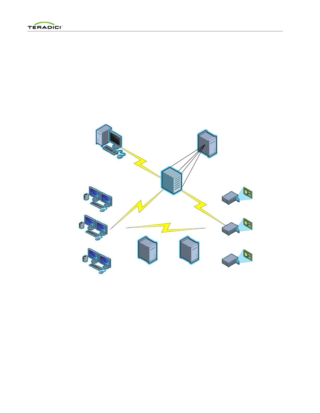
Figure 1-1 shows the recommended components found in a PCoIP deployment where
individual host and zero client devices are statically grouped tog ethe r (peered ). It shows the
MC used for peering and configuration. The figure does not show a connection broker, which
is required when hosts are dynamically assigned to zero clients as users log in.
Figure 1-1: PCoIP Deployment Components
1.1.1 Managing PCoIP Devices
A PCoIP deployment is made up of one or more PCoIP host and zero client devices. Each
device has multiple configuration settings that y ou can access and control using the following
mechanisms:
Device Web Interface
Although you can configure each device individually via a web-based administration
interface, you are encouraged to use the MC (especially as the deployment grows). This
ensures that all PCoIP devices are configured uniformly and that the MC database accurately
reflects the device configurati on settings.
For information about the device w eb inter face , see the PCoIP Zero Client and Host
Administrator Guide (TER1206003).
TER0812002 Issue 9 14

PCoIP Management Console User Manual
PCoIP Management Console
The management console for PCoIP protocol devices (MC) lets you centrally manage a
PCoIP deployment. It lets you:
• Access and update the configuration of your PCoIP devices
• Apply the same configuration settings to groups of devices
• Update device firmware
• Reset devices
• Control the power state of host devices that support power management
• Power off zero client devices
• View status information
• Manage the monitoring of device event logs
• Automatically configure newly discovered zero clients with a profile (op tionally with
firmware and OSD logo) based on device password, IP address and DHCP option
values
The MC is packaged as a VMware virtual machine (VM) and runs on VMware Player. This
lets you install and run the MC on any host machine that can run VMware Player. You can
also install and run the MC on any VMware ESX server. See section 2.4 for details on
installing the MC into your existing VMware ESX server.
A web browser is used to access and control the MC.
The MC must be connected to the same network to which the PCoIP devices are connected.
This lets the tool communicate with the PCoIP devices.
Connection Broker
A connection broker is an optional component that lets you manage user access to computing
resources. Note that this component is not shown in Figure 1-1. In a PCoIP deployment, a
connection broker is used to assign connections between PCoIP host and zero client devices.
Deployments having the following requirement must install a connection broker:
• hosts are dynamically assigned to zero clients based on the login credentials of the
person using the zero client
1.1.2 DNS Server
Figure 1-1 shows a DNS server with the MC DNS SRV record. This component is optional,
but highly recommended. The MC must discover the PCoIP host and zero client devices, and
the MC DNS SRV record facilitates automatic device discovery. You can also install a
connection broker DNS SRV record on the DNS server. PCoIP devices use this record to
notify the connection broker of their existence.
When a PCoIP device boots, it reads these records, which contain the addresses of the MC
and/or connection broker. After reading the records, the device sends messages to the MC
and/or connection broker notifying them of the devices existence. This ensures the MC and/or
connection broker is aware of the devices in the deployment as they are powered on.
The MC DNS SRV record is not required when one of the following conditions is true:
• PCoIP DHCP Vendor Class Options are configured in the DHCP server. See section
1.3.3.2 for details on configuring these options.
TER0812002 Issue 9 15

PCoIP Management Console User Manual
• All PCoIP devices in a deployment reside on the same network subnet as the MC. In
this situation, the MC can find the devices using SLP discovery. All devices have the
Enable SLP Discovery configuration setting set to True.
• The PCoIP MC DNS-Based Discovery Prefix setting for all devices is set to the
hostname prefix of the MC. You can only access this setting through the MC. You
cannot access it through the device web interface or zero client OSD interface.
Section 1.3.3.3 describes how PCoIP devices use the PCoIP MC DNS-Based
Discovery Prefix setting to contact the MC. It also describes the system requirements
to use this option.
If none of the previous conditions are true, include a DNS server in your system and install
the MC DNS SRV record. See section 1.3.3.1 for details on installing this record.
1.1.3 DHCP Server
A DHCP server with the PCoIP DHCP Vendor Class options (shown in Figure 1-1) is also an
optional component that is highly recommended. Like MC DNS SRV records, DHCP options
facilitate automatic device discov ery. You can use these options in place of a DNS SRV
record.
When a PCoIP device boots, it sends DHCP option 60 containing a PCoIP Vendor ID and
requests DHCP option 43, which contains the address of the MC. After receiving the address,
the device sends messages to the MC advertising its existence.
The PCoIP DHCP Vendor Class options are not required when one of the following
conditions is true:
• The MC DNS SRV record is installed in the DNS server. See section 1.3.3.1 for
details on installing this record.
• All PCoIP devices in a deployment are locate d on the same network subnet as the
MC. In this situation, the MC can find the devices using SLP discovery. All devices
have the Enable SLP Discovery configuration setting set to True.
• The PCoIP MC DNS-Based Discovery Prefix setting for all devices is set to the
hostname prefix of the MC. You can only access this setting through the MC. You
cannot access it through the device web interface or zero client OSD. Section 1.3.3.3
describes how PCoIP devices use the PCoIP MC DNS-Based Discovery Prefix
setting to contact the MC. It also describes the system requirements to use this
option.
If none of the previous conditions are true, include a DHCP server in your system and
configure the PCoIP DHCP Vendor Class options. See section 1.3.3.2 for details on
configuring this record.
Note: DHCP Options discovery is only available on PCoIP devices with firmware version
3.5.0 or higher.
1.2 Management Console Limitations
This section describes some limitations of the MC.
TER0812002 Issue 9 16

PCoIP Management Console User Manual
• PCoIP devices managed by the MC must be loaded with firmware release 0.19 or
greater. The MC cannot discover devices loaded with older firmware releases. You
must use the device web interface to load and activate new firmware on each device
running firmware releases less than or equal to 0.18. See the PCoIP Zero Client and
Host Administrator Guide (TER1206003) for more details.
• The current release of the MC is only compatible with versions 3.0 and higher of the
Firefox web browser and versions 7 and 8 of the Internet Explorer web browser.
Support for additional browsers will be included in future releases of the MC.
• The MC supports linking PCoIP host and zero client devices in fixed seating mode
where the same zero client always connects to the same host. If dynamically
assigning zero clients to hosts is required, include a connection broker in the
deployment.
• The MC supports managing up to 2000 PCoIP devices. The tool may be able to
support more than 2000 devices, but the current version was tested with a maximum
of 2000 devices. Support for more than 2000 devices will be included in a future
release of the tool. If your deployment has more than 2000 devices, contact your
PCoIP equipment supplier for help on managing more than 2000 devices.
1.3 Management Console Concepts
This section describes some key concepts to note before using the MC.
1.3.1 Groups and Profiles
The MC manages the PCoIP devices using two important concepts (groups and profiles):
• Profile: a set of device configuration settings
• Group: a set of one or more devices with a single profile
Figure 1-2 shows an example of how groups of host devices could be related to profiles. The
figure shows three groups of devices. Two of the groups share the same profile. In this
example, configuration settings defined in the Development Profile are written to the devices
in the R&D and Engineering groups.
TER0812002 Issue 9 17

PCoIP Management Console User Manual
Figure 1-2: Management Console Groups and Profiles
Note some important rules regarding groups and profiles:
• Each group has only one profile associated with it.
• The same profile can be associated with multiple groups.
• All configuration settings in a profile are written to all devices in a group when the
profile is applied to the group.
• A profile can contain values for every configuration parameter but this is not
required. You can define a profile that contains a subset of the configuration
parameters.
• If the firmware on a device is updated when a profile is applied, the pro file set ting s
are written to the device after the new firm ware is activated.
• Profiles contain settings that let users specify if a device’s firmware is updated based
on the version of the firmware running on the device.
• When profile settings are written to devices the settings might not take effect
immediately. Some settings are activated after a device is reset. Profile settings that
require a reset are preceded by the
symbol within the MC Profile Set Properties
and Device Details webpages. Consider resetting your devices in the deployment
after updating device configuration settings.
• When devices are added to a group and the group profile has not changed, apply the
profile to the newly added devices and not the entire group. This minimizes the
number of device resets.
1.3.2 Fixed Seating
The MC lets you link individual host and zero client devices so that each zero client always
establishes a connection to the same host. This relat ion ship is cal led fixed sea ting . To
dynamically assign hosts to zero clients when your users log in, you must install a connection
broker. The MC does not support dynamically assigning hosts to zero clients.
TER0812002 Issue 9 18

PCoIP Management Console User Manual
1.3.3 Device Discovery
The MC must discover PCoIP devices before it can manage them. The MC supports
discovering devices in a deployment using one or more discovery mechanisms:
Recommended approaches:
• Install a MC DNS SRV record. When DNS SRV record discovery is used, the PCoIP
devices advertise themselves to the MC. Devices that use the DNS server can find the
MC. If DNS-SRV discovery is not enabled, the MC must seek out and find devices
using methods that are often subject to limitations, such as being unable to search
more than its local subnet.
Note: Do not install a DNS SRV record if:
• Your network does not have a DNS server.
• You want to have multiple instances of the MC on your network to manage subsets
of your PCoIP devices. If you install a service record, the devices point to only one
instance of the MC.
See section 1.3.3.1 for details on installing a DNS SRV record.
• Install PCoIP DHCP Vendor Class. When DHCP Options discovery is used, the
PCoIP devices advertise themselves to the MC. Devices that use the DHCP server
can find the MC. If DHCP is not enabled, the MC must locate devices using methods
that are often subject to limitations, such as being unable to search more than its local
subnet.
Note: Do not insta ll DH C P O p tion s if:
• Your network does not have a DHCP server.
• You have PCoIP devices with a firmware version earlier than 3.5.0 in the network.
DHCP Options discovery is only available to PCoIP devices with firmware version
3.5.0 or higher.
See section 1.3.3.2 for details on configuring DHCP Vendor Class Options.
If you cannot install a DNS SRV record or DHCP Vendor Class Options:
• You may be able to configure the devices to automatically notify the MC of their
existence. PCoIP devices support a configuration setting called the PCoIP MC DNS-
Based Discovery Prefix.
Note: You can only access the PCoIP MC DNS-Based Discovery Prefix setting using
the MC. You cannot access it through the device web interface or zero client OSD
interface.
See section 1.3.3.3 for details.
• If you cannot install a DNS SRV record or use the PCoIP MC DNS-Based
Discovery Prefix configura tion setting, the fin al auto mated device discovery option
available is SLP discovery. This device discovery method imposes a restriction that
limits its usefulness. To use this feature, all PCoIP devices and the MC must reside
on the same network subnet.
• If a deployment cannot support any of the previous device discovery options, you can
use the MC to configure devices. The MC suppor ts a manual discovery feature that
lets the MC find devices.
TER0812002 Issue 9 19
PCoIP Management Console User Manual
Note: If you use this approach, note that if a device has DHCP enabled, the MC loses
contact with a device if its IP address changes. Should this occur, you must perform
another manual discovery search to find devices that were assigned new IP addresses.
See section 1.3.3.4 for more details.
1.3.3.1 Installing a DNS Service Record on the DNS Server
Before you can install the DNS service record:
• The deployment must have a DNS server in the network
• Two DNS records must be installed on the DNS server
1. An A record (name record) for the MC
2. A SRV record (service record) created
Note: The following steps are an example of how to install a DNS SRV record to a DNS
server in Windows Server 2003. If you use a different type of server, modify the steps
accordingly.
To add the MC DNS SRV record to DNS server in Windows Server 2003:
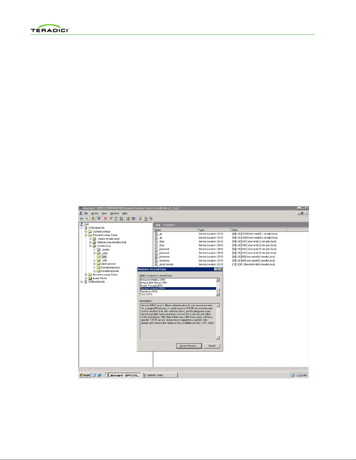
1. Enter DNS service configuration on domain controller.
2. Navigate to the local domain, and then selec t the _ tcp entry folder.
Figure 1-3: DNS Service Configuration Menu
3. Right-click, and then select Other New Records …
4. Select Service Location (SRV).
TER0812002 Issue 9 20
PCoIP Management Console User Manual
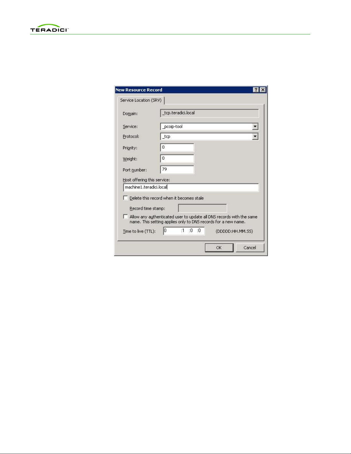
5. Fill in the entries as shown in Figure 1-4. (Enter the hostname where th e MC is instal led
under the heading Host offering this service.)
Note: The PCoIP devices do not use the Port Number setting. You can choose to set it to
50000 to reflect the listening port of the CMI server.
Figure 1-4: DNS Service Location (SRV) Dialog Box
1.3.3.2 Configuring DHCP Vendor Class Options on the DHCP server
Before you can install the DHCP options:
• The deployment must have a DHCP server in the network.
• The PCoIP devices must enable DHCP to send a request and receive the address of
the MC in response.
• The DHCP server must support both DHCP Options 60 (Vendor class identifier) and
43 (Vendor specific information). See RFC2132 for details on the DHCP options.
Note: The following steps are an example of how to configure DHCP Vendor Class Options
in a DHCP server in Windows Server 2003. If you use a different type of server, modify the
steps accordingly.
To add the PCoIP DHCP vender class options to the DHCP server in Windows Server 2003:
1. Enter the DHCP service configuration on the DHCP Server console.
2. Right-click the DHCP server in the tree, and then choose Define Vendor Classes…
3. Click Add to add a new DHCP Vendor Class.
4. Enter PCoIP Endpoint in the Display name field.
5. Enter PCoIP Endpoint in the ASCII column as the Vendor ID.
TER0812002 Issue 9 21
PCoIP Management Console User Manual
Note: For Cisco VXC 2111 and VXC 2211 PCoIP devices with firmware version 4.0.0 or
higher use VXC2111 and VXC2211 respectively as the Vendor ID.
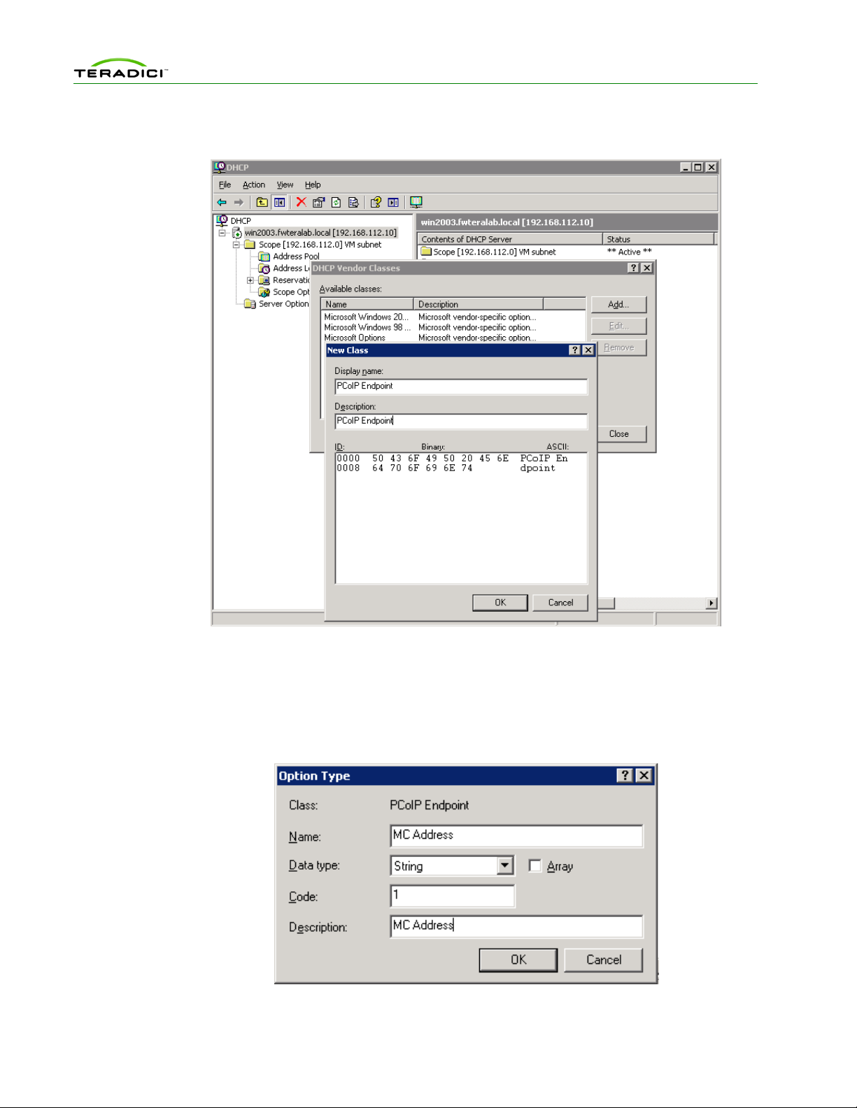
Figure 1-5: Add a new DHCP Vendor Class Configuration
6. Click OK to save and close the dialog.
7. Right-click the DHCP server in the tree, and then choose Set Predefined Options…
8. Select PCoIP Endpoint as the Option class, and then click Add…
9. Enter the name MC Address, data type String, code 1, and description MC Address,
and then click OK.
Figure 1-6: Add a DHCP Option Type Dialog Box
TER0812002 Issue 9 22
PCoIP Management Console User Manual
10. Click OK to save and close the dialog.
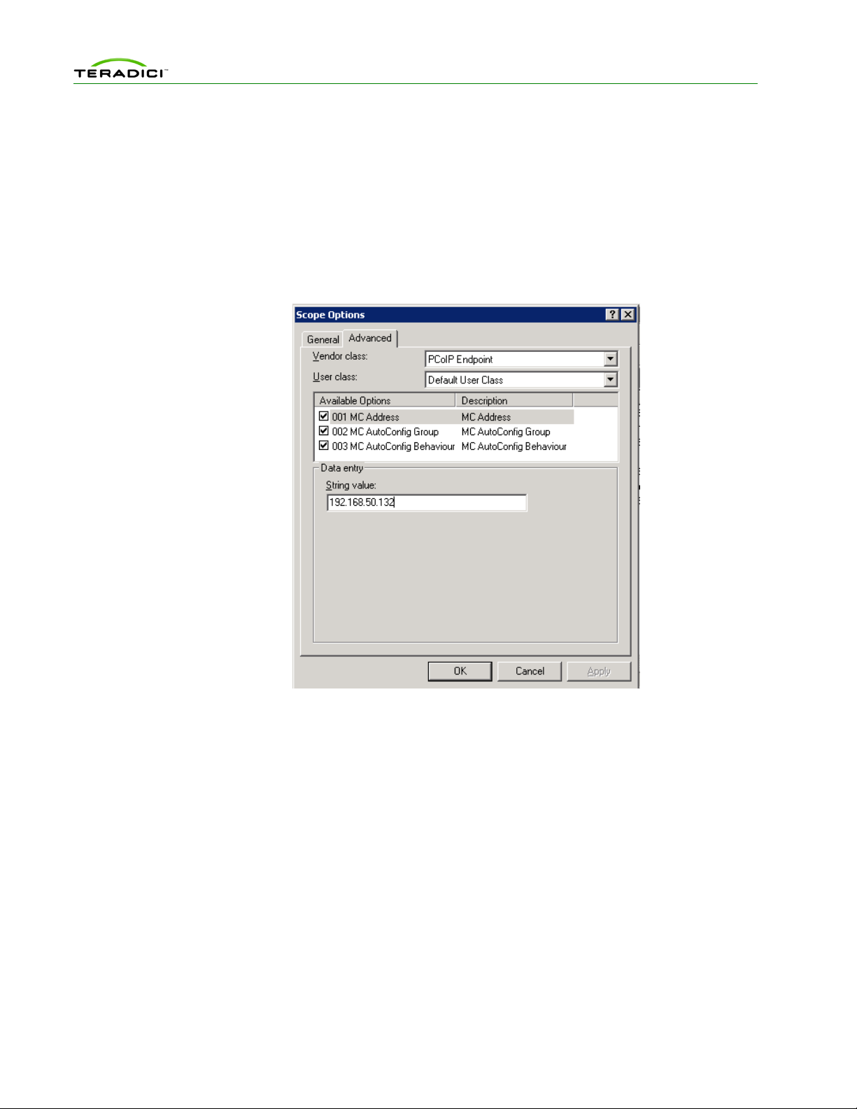
11. Expand the tree for the DHCP server, and expand the tree for the Scope to which you
want to add options.
12. Right-click Scope Options, and then choose Configure Options…
13. Click the Advanced tab, and then select the PCoIP Endpoint Vendor class.
14. Enable the checkbox for the MC Address, and then enter a valid MC IP address in the
Data entry field.
15. Click OK to save.
Figure 1-7: DHCP Scope Options Dialog Box
Optionally, you can add MC AutoConfig Group and MC AutoConfig Behavior options in
the PCoIP Endpoint vendor class. Add the options in the Predefined Options and Values
dialog using the following values.
• MC AutoConfig Group: Enter the name MC AutoConfig Group, data type String,
code 2, and description MC AutoConfig Group.
• MC AutoConfig Behavior: Enter the name MC AutoConfig Behavior, data type
Byte, code 3, and description MC AutoConfig Behavior.
Then enter the data entry in the Scope Options dialog.
1. MC AutoConfig Group: String value of a group name
2. MC AutoConfig Behavior: Byte value representing one of the following options
0. AutoConfig: All new devices
Persistent AutoConfig: Only when device is in MC AutoConfig Group
1. AutoConfig: All new devices
Persistent AutoConfig: All grouped devices
TER0812002 Issue 9 23

PCoIP Management Console User Manual
2. AutoConfig: None
Persistent AutoConfig: None
MC AutoConfig Behavior option is only used when MC AutoConfig Group option is
configured. It is recommended to configure both options together.
See section 1.3.4 for details on using the DHCP options for AutoConfig.
1.3.3.3 PCoIP Management Console DNS-Based Discovery Prefix
Each PCoIP device reads the PCoIP MC DNS-Based Discovery Prefix setting when it
boots. If this setting is not blank during startup, the device tries to contact the MC by
combining the string stored in this setting with variations of the domain name hierarchy.
System Requirements
The system requirements for MC DNS-Based Discovery are as follows:
• The PCoIP devices and MC must be located within the same domain name hierarchy
tree (for example, if a PCoIP device is located in the domain
sales.europe.companyname.com, then the MC’s domain name can be any one of:
sales.europe.companyname.com, europe.companyname.com, or companyname.com).
• The PCoIP devices must enable DHCP to get the domain name and hostname (to get
DHCP options 15 and 12 respectively).
• The DHCP server must support either DHCP options 12 (hostname), 15 (domain
name), or both. See RFC2132 for details on the DHCP options. If the DHCP server
only supports DHCP options 12, the hostname string must contain the domain name.
• PCoIP devices managed by a specific MC must have the PCoIP MC DNS-Based
Discovery Prefix setting equal to the MC’s hostname prefix (for example, if the
MC’s FQDN is pcoip_mc1.europe.companyname.com, then the field must equal
pcoip_mc1).
Algorithm
Each time a PCoIP device boots it executes the MC DNS-based discovery algorithm if the
PCoIP MC DNS-Based Discovery Prefix setting is non-blank. The algorithm uses the
setting and the domain name hierarchy to search for a MC.
The PCoIP device gets the domain name string from the DHCP server using DHCP options
15. Since some DHCP servers may not have DHCP options 15 implemented, the device also
gets the hostname using DHCP options 12 (assumed to include the domain name).
Since the device and MC may not be on the same domain (but must be within the same
hierarchy), the device creates many FQDN variations using the results from DHCP options
12 and 15. With each FQDN variation, the hostname prefix remains constant while the
domain hierarchy level changes.
The device sequentially attempts each FQDN possibility until a hit is found, at which point
the device completes the DNS-based discovery. The algorithm may take several minutes to
find the correct FQDN address of the MC (this depends on the number of levels in the
domain name hierarchy and the MC load).
In detail, the algorithm works as follows:
1. The device uses domain name variations based on the DHCP options 15 string. For each
FQDN possibility, the device attempts to transmit a status message to the MC at the
FQDN.
TER0812002 Issue 9 24

PCoIP Management Console User Manual
2. If the transmission times out, the device creates the next FQDN variation by proceeding
one level up the domain hierarchy. The last domain name attempted has a single dot in
the string.
3. After exhausting the FQDN possibilities (based on the DHCP options 15 string), the
device waits for five minutes and then uses hostname variations based on the DHCP
options 12 string.
4. After failing to contact a MC using the DHCP options 12 string, the device waits for five
minutes and then cycles back to using DHCP options 15.
5. The device repeats this process until a MC is contact e d.
Example
In the following example, the DHCP options 15 returns sales.europe.companyname.com.
DHCP options 12 returns hostmachine1.sales.europe.companyname.com. Note that the
DHCP server may return no value for either option. The MC configured the PCoIP MC
DNS-Based Discovery Prefix setting in the device to equal pcoip_mc1.
The device creates the following FQDNs and sequentially attempts contact with the MC:
(attempt #1) pcoip_mc1.sales.europe.companyname.com
(attempt #2) pcoip_mc1.europe.companyname.com
(attempt #3) pcoip_mc1.companyname.com
<device delays for 5 minutes>
(attempt #4) pcoip_mc1.hostmachine1.sales.europe.companyname.com
(attempt #5) pcoip_mc1.sales.europe.companyname.com
(attempt #6) pcoip_mc1.europe.companyname.com
(attempt #7) pcoip_mc1.companyname.com
<device delays for 5 minutes>
(attempt #8) pcoip_mc1.sales.europe.companyname.com (repeat 1-7)
...
Attempts 1 to 3 use the domain name from DHCP options 15 string. Failing to contact the
MC, the device uses the DHCP options 12 string for attempts 4 to 7. Failing transmissions for
attempt 4 to 7, the device cycles back to using DHCP options 15.
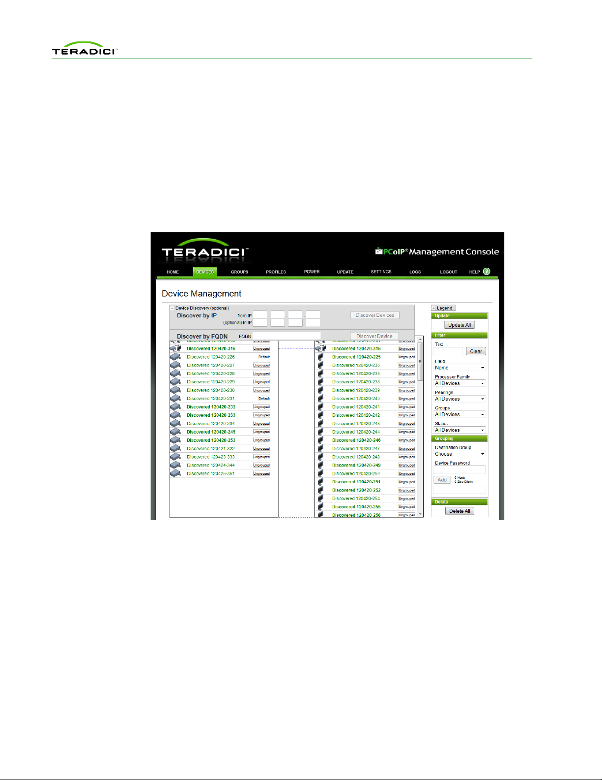
1.3.3.4 Manual Device Discovery
Manual device discovery is not an automated discovery mechanism. This mechanism
supports discovering devices that are powered on and connected to the network when the MC
is commanded to discover devices.
The MC supports manually discovering devices at a specific IP address, in a range of IP
addresses or at an FQDN. This option is useful to quickly begin using the MC or when a
deployment uses the PCoIP MC DNS-Based Discovery Prefix configuration setting
described in section 1.3.3.2. In this situation, you can discover devices using this feature and
configure the PCoIP MC DNS-Based Discovery Prefix setting of each device so the devices
contact the MC each time they boot.
Figure 1-5 shows the Management Console Device Management webpage with the Device
Discovery feature highlighted.
TER0812002 Issue 9 25
PCoIP Management Console User Manual
• When the IP address of a device is known and the device has not been discovered
enter the address in the from IP field, and then select Discover Devices.
• When a device is on a specific subnet but its IP address is not known, you can
command the MC to discover the devices in a range of IP addresses using both the
from IP and (optional) to IP fields. After you specify the address range, select
Discover Devices.
Note that this process can take a few minutes to complete depending on the number of
addresses searched. A status bar appears w hi le the tool discov ers dev ices.
• When the FQDN of a device is known and the device is not discovered, enter the
FQDN in the FQDN field and select Discover Devices.
Figure 1-8: Management Console Manual Device Discovery Feature
1.3.4 AutoConfig
When the MC discovers new PCoIP zero clients, it automatically adds them to a group and
applies the group’s profile. You can create AutoConfig rules to let one group have one or
more criteria defined.
The MC supports the following criteria to decide how zero clients are autom atically assig ned
to groups using AutoConfig:
• Each group can have an optional AutoConfig rule associated with it.
• Rules are sets of optional password settings and optional IP address ranges:
o No Password: Add discovered zero clients to this group if they have no
password configured.
TER0812002 Issue 9 26

PCoIP Management Console User Manual
o Password: Add discovered zero clients to this group if they have the identical
password configured for the criteria.
o IP address range: Add discovered z ero clien ts to this group if the IP address
falls within the range configured by the criteria. Not specifying an IP address
range adds zero clients that match the password criteria.
o DHCP Option Mat ch in g : Add discovered zero clients to this group if their
PCoIP DHCP option values are configured so that the group name is set in the
MC AutoConfig Group option and the MC AutoConfig Behavior option is not
set to 2.
See section 1.3.3.2 for details on configuring DHCP Vendor Class Options.
When a zero client is discovered:
1. The device is listed in the AutoConfig status table with a status of Not Started.
2. The zero client IP address and password are compared against all AutoConfig rules.
3. If a match is found, the zero client is added to that group.
4. If the group‘s profile contains a firmware rule, the firmware is applied if it passes the
criteria and the device is rebooted.
5. The rest of the profile‘s properties are now applied to the device.
6. After applying the profile‘s OSD logo and properties, the zero client is rebooted.
See section 4.3.3 for more details on configuring AutoConfig.
TER0812002 Issue 9 27

PCoIP Management Console User Manual
1.7.1
1.4 Management Console and Firmware Version Compatibility
Table 1-1: Management Console and Firmware Version Compatibility
MC Version Supports FW Version Fully Configures FW Versions
1.8.0 0.19-current 0.19-4.0.1
Added the ability to:
• Configure certification check mode in View
Connection Server mode
• Enable certification check mode lockout in
View Connection Server mode
• Clear trusted View Connection Server
address cache
• Configure session negotiation security level
• Configure SNMP community name
• Configure Imprivata OneSign applian ce
verification
• Configure Imprivata OneSign des ktop na me
mode
• Enable proximity reader beep
• Configure session lost timeout
• Enable session disconnect hotkey
• Configure display topology
• Enable monitor emulation on video port 3 and
4
• Enable Wake-on-USB
• Enable Wake-on-LAN
• Enable power on after power loss
• Enable AES-256
0.19-current 0.19-3.5.1
Added the ability to:
• Enable session login overlay: “Preparing
Desktop…”
• Choose the Turkish F keyboard layout
TER0812002 Issue 9 28
 Loading...