

Teradici t310, PCoIP Administrator's Manual

PCoIP Administrator's Guide
TER0606004
Issue 16

PCoIP Administrator's Guide
TeradiciCorporation
#101-4621 Canada Way, Burnaby, BC V5G 4X8 Canada
p +1 604 451 5800 f +1 604 451 5818
www.teradici.com
The information contained in this document r epresents the current view of Ter adici Corporation as of the date of
publication. Because Teradici must respond to changing market conditions, it should not be interpreted to be a
commitment on the part of Teradici,and Teradici cannot guarantee the accuracy of any information presented after the
date of publication.
This document is for informational pur poses only.TERADICI MAKES NO WARRANTIES, EXPRESS, IMPLIED OR
STATUTORY, AS TO THE INFORMATION IN THIS DOCUMENT.
Complying with all applicable copyright laws is the responsibility of the user. Without limiting the rights under copyright,
no part of this document may be reproduced, stored in or introduced into a retrieval system, or transmitted in any form or
by any means (electronic, mechanical, photocopying, recording, or otherwise), or for any purpose, without the express
written permission of Teradici Corporation.
Teradicimay have patents, patent applications, tr ademarks, copyrights, or other intellectual property r ights covering
subjectmatter in this document. Except as expressly provided in any written license agreement from Teradici, the
furnishing of this document does not give you any license to these patents, trademarks, copyrights, or other intellectual
property. Visit http:\\Teradici.com\pat for more information.
© 2012 Teradici Cor poration. All r ights reserved.
Teradici, PC-over-IP, and PCoIP are registered trademarks of T eradiciCorporation.
The names of actual companies and products mentioned herein may be the trademarks of their respective owners.
TER0606004 Issue 16 2

Revision History
Version Date Description
Updated for Firmware Release 4.0.0
l Security enhancement when connecting to VMware View
Connection server: New VCS Certificate Check Mode
options allow users to configure the client to reject, warn, or
allow an unverifiable connection. This feature is available
from both the Administrator Web Interface (AWI) and the
Online Screen Display (OSD). You can also enable the VCS
Certificate Check Mode Lockout option on the AWI to
prevent users from changing the VCS Certificate Check
Mode options from the OSD.
l Security enhancement: TLS 1.2 and Suite-B TLS ciphers are
now supported for zero clients and host cards.
l New "Preparing desktop..." overlay can be enabled for all
connection types.
l When configuring a View Connection Server + Imprivata
OneSign connection from the AWI, you can now configure
the client to connect to any appliance or only to appliances
with verified certificates.
l When configuring a Direct to Host session, the Wake host
from low power state setting in the advanced options now
lets you configure the host's IP address as well as its MAC
address. In addition, the Peer MAC Address field has been
16 May 18, 2012
removed from the OSD Direct to Host advanced settings
options. The wake host feature is now configured from the
AWI only.
l OSD advanced View Connection Server options now
contain a new Desktop Name to Select setting. Previously,
this setting was only available from the AWI.
l The OSD now lets you configure a View Connection Server
+ Auto-Logon connection. Previously, this connection could
only be configured using the AWI and PCoIP Management
Console (MC).
l The default OSD screen-saver timeout value has been
changed to 300 seconds. Previously, this setting was
disabled by default (i.e., set to 0 seconds).
l New OSD Display options let you configure the native
resolution of a display when the display cannot be detected
and default EDID information is sent.
l OSD Display Topology enhancements make the topology
easier to configure. In addition, you no longer have to reboot
the zero client after changing the Rotation setting for a
display.
l The OSD interface has a revised color scheme and logo
placement.
PCoIP Administrator's Guide
TER0606004 Issue 16 3

Version Date Description
Updated for Firmware Release 3.5.0
l Proximity card based SSO with Imprivata OneSign server
support
l IEEE 802.1X network authentication
l IPv6 support
l DHCPv6 support
l Self-help link added: Lets you configure an end-user link for
access to self-help information
l Limited USB 2.0 support for View 4.6 or later deployments
(bulk only for devices directly connected to root ports)
l Enhanced imaging controls
l View Connection Server cache increased up to 25 entries
l Audio Line-in Mode
l Enhanced logging modes
15
December 2,
2011
l Revamped User Interface: Improved the layout of the pages
and screens:
o
Home and Statistics pages: Added statistics,
consolidated information
o
Session page: consolidated information/pages for
improved user experience
o
Attached Devices page: expose the resolution, new
onscreen legend to explain statistics
l Certificate management (at this time, limited to 802.1X client
certificate)
l Monitor alignment support
l Disconnect Message Filter field added: Lets you control
the message that appears when a session disconnects
l New hotkey to reset zero client to factory default
configuration
l New Session Connection Type field
l New Pipeline Processing Rate field
PCoIP Administrator's Guide
14
September
16, 2011
13 June 8, 2011
TER0606004 Issue 16 4
Updated for Firmware Release 3.4.1
l Support for .Net cards
Updated for Firmware Release 3.4.0
l New banner at the top of the Administrative Web Interface
page
l RDP is no longer supported
l Diagnostic enhancements:
o
Syslog support
o
Additional log reporting for specific categories of
messages (such as Audio, USB, video)
l Reset Host CPU button from Host CPUpage removed
l New OSD page in the User Settings window called Touch
Screen. Lets users configure and calibrate Elo
TouchSystems touch screen displays with IntelliTouch

Version Date Description
surface acoustic wave and AccuTouch five-wire resistive
touch screen technologies.
PCoIP Administrator's Guide
12
11
April 18,
2011
February
2011
10 Apr 06, 2010
9 Dec 08, 2009
Updated for Firmware Release 3.3.1.
l Updated for Firmware Release 3.3.
l Incorporated information from Administrative notes (which
documented features for Firmware Release 3.2.0).
l Updated for Firmware Release 3.1.0.
l Updated On Screen Display (OSD) section with appropriate
references to the Administrative Web Interface section.
l Updated Appendix B: Client Language and Keyboard
Support to include Belgian, Danish, Finnish, Norwegian,
Polish, Swedish and Turkish keyboards.
l Updated for Firmware Release 3.0
l Simplified to endpoint terms “client” and “host card”
l Updated description for Home webpage
l Added description for Enable AES-128-GCM and Enable
SALSA20-256-Round12
l Updated description to use kbps for Bandwidth
l Updated description for OSD configuration
l Updated description for USB permission
l Updated description for Enable Microsoft Windows Vista /
Windows 7 64-bit Mode for Windows 7 64-bit
l Updated Session Statistics description for improved session
stats
l Added USB Over Current Notice Overlay description
l Updated Appendix B: Client Language and Keyboard
Support to include the Korean dubeolsik keyboard
8 Oct 22, 2009
7 Jun 15, 2009
6 May 14, 2009
TER0606004 Issue 16 5
l Updated for Firmware Release 2.3
l Added notes about Host and Portal webpage banners
l Added description for SNMP enable feature
l Updated for Firmware Release 2.2
l Added description for enable display override
l Clarified Network Connection Lost overlay description (2
seconds of network inactivity)
l Updated for Firmware Release 2.1
l Modified to note some PCoIP devices have password
webpage and password protection disabled by default
l Updated to note some webpages are only available for Host
or Portal
l Added Domain Name and FQDN parameter details

Version Date Description
l Added description for Label webpage
l Added description for VMware View webpage
l Updated description (Device Bandwidth Floor) for
Bandwidth webpage
l Updated figure for Image webpage
l Added description for Host Driver Function webpage
l Updated description (removed Enable Audio Compression)
for Audio webpage
l Improved document wording and fixed errors
5 Nov 25, 2008
4 Sep 12, 2008
l Updated for Firmware Release 1.8
l Adjusted formatting; replaced bitmap graphics w/ GIFs to
reduce file size
l Updated for Firmware Release 1.4
l Added menu navigation overview (Figure 1 2:
Administrative Web Interface Overview)
l Added Initial Setup/Home webpage information
l Added Initial Setup webpage details
l Updated Enable Auto-Reconnect detail
l Updated Ethernet Mode for Host
l Added Enable Vista64 Mode
l Added Half-Duplex Overlay
l Added Video Source Overlays)
PCoIP Administrator's Guide
3 May 26, 2008
2 April 7, 2008
l Updated for Firmware Release 1.00
l Updated text and figure references to Portal
l Added warning to Ethernet Mode section concerning PC-
over-IP Half-Duplex in compatibility
l Clarified when Device Bandwidth Limit and Device
Bandwidth Target are applied
l Updated USB Permissions documentation for USB
authorization/unauthorization functionality
l Added USB devices status descriptions in Table 1 13: VPD
Information
l Attached Devices - USB Devices
l Augmented definitions (see Definitions Section)
l Updated for Firmware Release 0.19
l Updated PCoIP Processor Information description
l Removed VLAN place holder from Network Configuration
Webpage
l Added Maximum MTU Size in Network web configuration
l Added DNS SRV in Discovery web configuration
l Updated Session web configuration ordering
l Added Device Bandwidth Target to Bandwidth web
configuration
TER0606004 Issue 16 6

Version Date Description
l Updated RDP web configuration
l Added Maximum Initial Image Quality to Image web
configuration
l Added Time web configuration
l Added Firmware Part Number in Version web information
l Updated Firmware Upload build filename web information
l Updated RDP OSD configuration
l Added Firmware Part Number in Version OSD information
l Clarified Bandwidth and Image Configuration Example
l Removed TERA1x00 Firmware Defaults appendix to
enhance in separate Application Note
l Updated for Firmware Release 0.20
l Added Bandwidth Statistics
l Updated RDP compatibility information
PCoIP Administrator's Guide
1
January 15,
2008
Initial release
TER0606004 Issue 16 7

PCoIP Administrator's Guide
Contents
Revision History 3
Table of Figures 12
Table of Tables 16
Definitions 18
1 Introduction 20
1.1 About this Document 20
1.2 Menu and Page Overview 21
2 Administrative Web Interface Overview 25
2.1 About the Page Layout 25
2.2 Supported Web Browsers 26
2.3 Administrative Web Interface IP Address 27
2.4 Administrative Interface Security 27
2.4.1 Installing the CA Root Certificate 27
2.5 Logging In 27
2.6 Viewing the Home Page 28
2.7 About the Administrative Interface Menus 32
2.7.1 Viewing the Configuration Menu 33
2.7.2 Viewing the Permissions Menu 34
2.7.3 Viewing the Diagnostics Menu 34
2.7.4 Viewing the Information Menu 34
2.7.5 Viewing the Upload Menu 34
3 Working with the On Screen Display (OSD) 35
3.1 About the Connect Window 35
3.1.1 Connect Button 36
3.2 About the OSD Options Menu 36
4 Configuring the Device 37
4.1 Initial Setup Page 37
4.2 Configuring the Network Settings 41
4.3 Configuring the IPv6 Settings for a Device 44
4.4 Adding Custom Information for the Device 47
4.5 Configuring the Discovery Mechanism 49
4.6 Configuring the SNMP Agent 51
4.7 Configuring the Session 51
TER0606004 Issue 16 8

PCoIP Administrator's Guide
4.7.1 Configuring a Direct Session 53
4.7.2 Configuring a Direct Session with SLP Host Discovery 58
4.7.3 Configuring a VMware View Connection 62
4.7.4 Configuring Kiosk Mode 70
4.7.5 Configuring a View Connection Server + Imprivata OneSign Connection 76
4.7.6 Enabling or Disabling Connection Management 80
4.8 Controlling the Bandwidth for PCoIP Sessions 85
4.9 Setting the User Interface Language 86
4.10 Configuring the OSD Screen-saver Timeout 88
4.11 Adjusting the Image Quality 89
4.12 Enabling the Host Driver Function 94
4.13 Configuring the NTP Parameters 95
4.14 Updating the Password for a Device 96
4.15 Resetting the Parameters to Factory Default Values 97
4.16 Configuring the EDID Override Mode 99
4.17 Enabling Monitor Emulation 101
4.18 Enabling or Disabling the OSD Configuration Menus 102
4.19 Enabling or Disabling the Web Server 102
5 Setting up the User Permissions 104
5.1 Specifying USB Devices 104
5.2 Configuring the Audio Parameters 106
5.3 Setting up the Client's Power-off Permissions 107
6 Using the Diagnostic Tools 109
6.1 Viewing and Clearing Event Log Messages 109
6.1.1 Syslog Features 109
6.2 Controlling the Device Session 112
6.3 Viewing PCoIP Protocol Statistics 113
6.4 Working with the Host Information and Power State 117
6.5 Generating an Audio Test Tone from the Client 118
6.6 Viewing a Test Pattern on the Client's Display 119
6.7 Resetting the Device Processor 120
6.8 Determining if a Device is Reachable 121
7 Viewing Device Information 123
7.1 Viewing the Version Information 123
7.2 Viewing the Attached Devices 125
8 Uploading to the Device 128
8.1 Uploading Firmware to the Device 128
TER0606004 Issue 16 9

PCoIP Administrator's Guide
8.1.1 Firmware Upload Process Example: 128
8.2 Uploading a Logo to the Device 129
8.2.1 OSD Logo Upload Process Example 130
8.3 Uploading the Certificate 130
8.3.1 Uploading Certificates for 802.1X Authentication 131
9 Configuring the User Settings 132
9.1 Configuring VMware View Certificate Checking 132
9.2 Configuring the Mouse Settings 133
9.3 Changing the Keyboard Repeat Settings 134
9.4 Adjusting the Image Quality from the OSD 135
9.5 Configuring the Display Topology 135
9.6 Configuring the Touch Screen 138
9.6.1 Installing the Touch Screen to the Zero Client 139
9.6.2 Setting up the Touch Screen as a Bridged Device 139
9.6.3 Configuring the Zero Client to Automatically Log into a VMware View Host 140
10 About the Overlay Windows 142
10.1 Network Connection Lost Overlay 142
10.2 Preparing Desktop Overlay 142
10.3 USB Device Not Authorized Overlay 143
10.4 USB Over Current Notice Overlay 143
10.5 USB Device Not Supported Behind a High-speed Hub Overlay 143
10.6 Resolution Not Supported Overlay 143
10.7 Half Duplex Overlay 144
10.8 Video Source Overlays 144
11 Using Smart Cards with PCoIP Zero Clients 146
11.1 Smart Card Requirements 146
11.1.1 Virtual Desktop Environment 146
11.1.2 Supported USBCard Readers 146
11.1.3 CAC Smart Card Properties 147
11.1.4 .Net Smart Card Properties 147
11.1.5 Communication Protocol 147
11.1.6 Card Certificate Requirements 147
11.1.7 Tested Smart Card Models 147
11.2 Using a Smart Card to Connect to a VMware View Brokered Session 148
Appendix A: Usage Examples Overview 151
A.1 Peer-to-Peer Direct Connection Example 151
A.1.1 Configuring the Client Peer-to-Peer Operation 151
A.1.2 Configuring the Host Peer-to-Peer Operation 152
A.1.3 Initiating the Peer-to-Peer Session 153
TER0606004 Issue 16 10

PCoIP Administrator's Guide
A.2 DHCP and Enable Host Discovery Example 154
A.2.1 Configuring the Client for DHCP and SLP Discovery 154
A.2.2 Configuring the Host for Host DHCP and SLP Discovery 156
A.2.3 Initiating an SLP Discovery Session 158
A.3 USB Permissions Example 158
A.3.1 Authorizing USB Device By Class 158
A.3.2 Authorizing USB Device By Vendor/Product ID 159
Appendix B: Client Language and Keyboard Support 161
B.1 Languages Supported by the Client 161
B.2 Keyboard Layouts Supported by the Client 161
TER0606004 Issue 16 11

PCoIP Administrator's Guide
Table of Figures
Figure 2-1: Administrative Web Interface Home Page (Host) 26
Figure 2-2: Administrative Web Interface Log In Page 28
Figure 2-3: Administrative Web Interface Home Page (Host) 29
Figure 2-4: Administrative Web Interface Home Page (Client) 30
Figure 2-5: Administrative Web Interface Menu Overview 33
Figure 3-1: OSD Connect Window 35
Figure 3-2: Network Not Ready (detail) 35
Figure 3-3: Network Ready (detail) 35
Figure 3-4: OSD Connect Screen (Connecting) 36
Figure 3-5: OSDOptions Menu 36
Figure 4-1: Initial Setup Page (Host) 38
Figure 4-2: Initial Setup Page (Client) 39
Figure 4-3: Administrator Web Interface Network Page 41
Figure 4-4: OSD Network Page 42
Figure 4-5: Administrative Web Interface IPv6 Page 45
Figure 4-6: OSD IPv6 Page 46
Figure 4-7: Administrative Web Interface Label Page 47
Figure 4-8: OSD Label Page 48
Figure 4-9: Administrative Web Interface Discovery Page 49
Figure 4-10: OSD Discovery Page 50
Figure 4-11: Administrative Web Interface SNMP Agent Page 51
Figure 4-12: AWI Session Connection Type Options (Host) 52
Figure 4-13: AWI Session Connection Type Options (Client) 52
Figure 4-14: AWI Session Connection Type – Direct from Client (Host) 53
Figure 4-15: AWI Session Connection Type – Direct to Host (Client) 53
Figure 4-16: OSD Session Connection Type – Direct to Host 54
Figure 4-17: OSD Session Connection Type – Direct to Host (Advanced Settings) 54
Figure 4-18: AWI Session Connection Type – Direct from Host with SLPHost Discovery 58
Figure 4-19: OSD Session Connection Type – Direct to Host with SLP Host Discovery 59
Figure 4-20: OSD Session Connection Type – Direct to Host with SLP Host Discovery
(Advanced Settings) 59
Figure 4-21: AWI Session Connection Type – View Connection Server 62
Figure 4-22: OSD Session Connection Type – View Connection Server 63
TER0606004 Issue 16 12

PCoIP Administrator's Guide
Figure 4-23: OSD Session Connection Type – View Connection Server (Advanced Settings) 63
Figure 4-24: Enable Self Help Link Options 67
Figure 4-25: AWI View Connection Server with Auto-Logon 69
Figure 4-26: OSD View Connection Server with Auto-Logon 70
Figure 4-27: AWI Session Connection Type View Connection Server + Kiosk 71
Figure 4-28: OSD View Connection Server + Kiosk Advanced Options 72
Figure 4-29: OSDView Connection Server + Kiosk (Advanced Settings) 72
Figure 4-30: AWI Session Connection Type – View Connection Server + Imprivata OneSign 76
Figure 4-31: OSD Session Connection Type – View Connection Server + Imprivata OneSign 77
Figure 4-32: OSD View Connection Server + Imprivata OneSign (Advanced Settings) 77
Figure 4-33: AWI Connection Type – Connection Management Interface 81
Figure 4-34: OSDSession Page – Connection Management Interface 82
Figure 4-35: OSD Session Page – Connection Management Interface (Advanced Settings) 82
Figure 4-36: Administrative Web Interface Bandwidth Page 85
Figure 4-37: Administrative Web Interface Language Page 87
Figure 4-38: OSD Language Page 87
Figure 4-39: Administrative Web Interface OSD Page 88
Figure 4-40: OSD-OSD Page 89
Figure 4-41: Administrative Web Interface Image Page (Host) 90
Figure 4-42: Administrative Web Interface Image Page (Host) 90
Figure 4-43: Administrative Web Interface Image Page (Client) 91
Figure 4-44: OSD Image Page 92
Figure 4-45: Administrative Web Interface Host Driver Function Page 94
Figure 4-46: Administrative Web Interface Time Page 95
Figure 4-47: Administrative Web Interface Change Password Page 96
Figure 4-48: OSD Change Password Page 97
Figure 4-49: Administrative Web Interface Reset Page (Client) 98
Figure 4-50: OSD Reset Page 98
Figure 4-51: OSD Display Page 100
Figure 4-52: Administrative Web Interface Monitor Emulation Page 101
Figure 4-53: OSD Configuration – Hidden Menu Entries Option 102
Figure 4-54: Security Configuration – Enable Web Interface Option 103
Figure 5-1: Administrative Web Interface USBPage 105
Figure 5-2: Administrative Web Interface Audio Page (Host) 107
Figure 5-3: Administrative Web Interface Power Page (Client) 108
TER0606004 Issue 16 13

PCoIP Administrator's Guide
Figure 6-1: Administrative Web Interface Event Log Page 110
Figure 6-2: OSD Event Log Page 111
Figure 6-3: Administrative Web Interface Session Control Page 113
Figure 6-4: Administrative Web Interface Session Statistics Page (Host) 114
Figure 6-5: Administrative Web Interface Session Statistics Page (Client) 115
Figure 6-6: OSD Session Statistics Page 115
Figure 6-7: Administrative Web Interface Host CPU Page 118
Figure 6-8: Administrative Web Interface Audio Diagnostics Page 119
Figure 6-9: Administrative Web Interface Display Page 119
Figure 6-10: Administrative Web Interface PCoIP Processor Page 120
Figure 6-11: OSD PCoIP Processor Page 121
Figure 6-12: OSD Ping Page 122
Figure 7-1: Administrative Web Interface Version Page 123
Figure 7-2: OSD Version Page 124
Figure 7-3: Administrative Web Interface Attached Devices Page (Host) 125
Figure 7-4: Administrative Web Interface Attached Devices Page (Client) 126
Figure 8-1: Administrative Web Interface Firmware Page 128
Figure 8-2: Administrative Web Interface OSDLogo Upload Page (Client) 129
Figure 8-3: Administrative Web Interface Certificate Upload Page 130
Figure 9-1: VMware View Page 132
Figure 9-2: OSD Mouse Page 133
Figure 9-3: OSD Keyboard Page 134
Figure 9-4: OSDImage Page 135
Figure 9-5: Display Topology Page 136
Figure 9-6: OSD Touch Screen Page 138
Figure 10-1: Network Connection Lost Overlay 142
Figure 10-2: Preparing Desktop Overlay 142
Figure 10-3: USB Device Not Authorized Overlay 143
Figure 10-4: USB Over Current Notice Overlay 143
Figure 10-5: USB Device Not Supported Behind a High-speed Hub Overlay 143
Figure 10-6: Resolution Not Supported Overlay 144
Figure 10-7: Half Duplex Overlay 144
Figure 10-8: No Source Signal Overlay 144
Figure 10-9: Source Signal on Other Port Overlay 145
Figure 11-1: Accessing the Smart Card Message 148
TER0606004 Issue 16 14

PCoIP Administrator's Guide
Figure 11-2: Select Certificate Prompt 149
Figure 11-3: Certificate Details Window 149
Figure 11-4: Smart Card Holder Verification Window 150
Figure 12-1: Peer-to-Peer Connect Screen 153
Figure 12-2: Client Network Page DHCP Configuration 156
Figure 12-3: Host Network Page DHCP Configuration 157
Figure 12-4: USB Permissions Example: Class Authorization 159
Figure 12-5: USB Permissions Example: Entering Vendor ID and Product ID 160
Figure 12-6: USB Permissions Example: Vendor ID and Product ID Authorization 160
TER0606004 Issue 16 15

PCoIP Administrator's Guide
Table of Tables
Table 1-1: Configuration Menu 22
Table 1-2: Permissions Menu 22
Table 1-3: Diagnostics Menu 23
Table 1-4: Info Menu 23
Table 1-5: Upload Menu 23
Table 1-6: User Settings Menu 24
Table 2-1: Home Page Statistics 30
Table 4-1: Audio Parameters 39
Table 4-2: Network Parameters 40
Table 4-3: Session Parameters (Host) 40
Table 4-4: Session Parameters (Client) 40
Table 4-5: Network Page Parameters 42
Table 4-6: IPv6 Page Parameters 46
Table 4-7: Label Page Parameters 48
Table 4-8: Discovery Page Parameters 50
Table 4-9: SNMPAgent Page Parameters 51
Table 4-10: Session Page Parameters 55
Table 4-11: Session Page Parameters 60
Table 4-12: VMware View Page Parameters 64
Table 4-13: View Connection Server + Auto-Logon Parameters 70
Table 4-14: View Connection Server + Kiosk Parameters 73
Table 4-15: VMware View Page Parameters 78
Table 4-16: Connection Management Page Parameters 83
Table 4-17: Bandwidth Page Parameters 85
Table 4-18: Language Page Parameters 87
Table 4-19: OSDPage Parameters 89
Table 4-20: Image Page Parameters 92
Table 4-21: Time Page Parameters 95
Table 4-22: Change Password Page Parameters 97
Table 4-23: Reset Parameters 98
Table 5-1: USB Page Parameters 105
Table 5-2: USB Device Authorized/Unauthorized Entry Types 106
TER0606004 Issue 16 16

PCoIP Administrator's Guide
Table 5-3: Audio Page Parameters 107
Table 5-4: Power Page Parameter 108
Table 6-1: Event Log Parameters 111
Table 6-2: Session Control Page Parameters 113
Table 6-3: Session Statistics Page Parameters 116
Table 6-4: Host CPUPage Parameters 118
Table 6-5: Display Page Parameters 119
Table 6-6: PCoIP Processor Page Statistics 121
Table 6-7: Ping Page Parameters 122
Table 7-1: OSDVersion Page Parameters 124
Table 7-2: Attached Devices Page Statistics 126
Table 8-1: Firmware Page Parameters 128
Table 8-2: OSD Logo Page Parameters 129
Table 8-3: Administrative Web Interface Certificate Upload Page Parameters 130
Table 9-1: VMware View Page Parameters 133
Table 9-2: Mouse Page Parameters 134
Table 9-3: Keyboard Page Parameters 135
Table 9-4: Display Topology Page Parameters 136
Table 9-5: OSD Touch Screen Page Parameters 139
TER0606004 Issue 16 17

Definitions
Definition Description
CA Certificate Authorities
Connection Management Interface – interface provided by the host or
CMI
client, used to communicate with an external connection management
server
PCoIP Administrator's Guide
CMS
DDC Display Data Channel
DHCP Dynamic Host Configuration Protocol
DNS Domain Name System
DNS SRV Domain Name System Service Record
EDID Extended Display Identification Data
FQDN Fully Qualified Domain Name
GPU Graphics Processing Unit
GUI
HPDET Hot Plug Detect
MC PC-over-IP Management Console (PCoIPMC)
MIB Management Information Base
Connection Management Server – an external management entity (third
party) that manages and controls the host/client through the CMI interface
Graphical User Interface presented by the client On Screen Display when
not operating in a PC-over-IP session
MTU Maximum Transmission Unit
NTP Network Time Protocol
OS Operating System
OSD On Screen Display
PC-over-IP
PCoIP
PCoIP Zero Client
TER0606004 Issue 16 18
®
®
Personal Computer over Internet Protocol
Personal Computer over Internet Protocol (PC-over-IP)
Desktop side of PC-over-IP system (that is, client). For example, PCoIP
zero client or PCoIP integrated display)

Definition Description
PCoIP Host Host side of PC-over-IP system
PCoIP Administrator's Guide
RDP
Remote Desktop Protocol
Note: RDP is not supported in firmware releases after 3.2.2
SLAAC Stateless Address Auto-configuration
SLP Service Location Protocol
SNMP Simple Network Management Protocol
SSL Secure Socket Layer (security protocol)
TERA1100 Teradici device supporting PC-over-IP client functionality
TERA1200 Teradici device supporting PC-over-IP host functionality
VPD
Vital Product Data – Factory provisioned information to uniquely identify a
host or client
VPN Virtual Private Network
Zero client See PCoIP zero client
TER0606004 Issue 16 19

1 Introduction
As a user or administrator you can interact with your PCoIP®zero clients and host cards (or
"clients" and "hosts") through the embedded HTTPS web interface (i.e., Administrative
Web Interface) and On Screen Display (OSD). To minimize the total learning curve and
maximize the accessibility, the web interface and OSD are organized as similarly as
possible and are structured in a task-oriented fashion.
l Administrative Web Interface: Lets you configure the hosts and clients through an
Internet Web browser.
l OSD: Lets you configure the client through the graphical user interface (GUI).
Messages appear overlaid on the user display as required. The OSD has a subset of
parameters available in the Administrative Web Interface.
Note: This guide describes the interface for PCoIP protocol devices such as PCoIP zero
clients and PCoIP host cards. This document does not describe the Administrative Web
Interface for PCoIP software integrated into products such as VMware View®.
The configuration features are also available through some connection brokers and the
PCoIP Management Console (a web-based tool used to manage multiple PCoIP endpoints).
These features are not described in this guide. For more information on the PCoIP
Management Console, see the PCoIP Management Console User Manual (TER0812002).
PCoIP Administrator's Guide
1.1 About this Document
This document is divided into the following sections:
Title Description Section
Introduction
Administrative Overview This section describes the Administrative Web Inter-
On Screen Display
(OSD) Overview
Configuring the Device
Setting up User
Permissions
This section describes the document structure and
introduces you to the Administrative Web Interface and
OSD.
face (AWI), login details, and onscreen menus.
This section describes the OSD, how to log in, and its
menus.
This section describes the options available from the
Configuration menu. It covers the available
configuration parameters.
This section describes how to configure the options
from the Permissions menu (such as configuring the
USB devices, audio settings, and power-off
permissions).
1
2
3
4
5
Using the Diagnostic
TER0606004 Issue 16 20
This section describes how to use the options
6

PCoIP Administrator's Guide
Title Description Section
available from the Diagnostic menu. These options
Tools
Viewing Device
Information
Uploading to the Device
Configuring the User
Settings
help you troubleshoot the device by letting you view
device statistics, generate test tones and patterns,
reset the device, ping the device, and so on.
This section describes the options available in the
Information menu. These options let you see which
firmware version is currently installed on the device
and view the attached devices.
This section describes the options available in the
Upload menu. It describes the steps to upload firmware
to the device and steps to upload a logo that will
appear on the OSD Connect page. It also describes
how to upload the certificate.
This section describes the options available from the
User Settings menu in the OSD. These options
include configuring VMware View certificate checking,
changing the mouse cursor speed settings, changing
the keyboard repeat settings, changing the image
settings, and configuring the display topology.
7
8
9
About the Overlay
Pages
Using CAC Smart Cards
with PCoIP Zero Clients
Usage Examples
Client Language and
Keyboard Support
This section describes the overlay messages that can
appear during a PCoIP session.
This section describes which CAC Smart Cards are
supported and the steps you must take to connect the
CAC Smart Card to the device.
This section lets you see examples of things like
setting up a peer-to-peer direct connection, configuring
the device for DHCP, and enabling host discovery.I
This section lists the language and keyboards
supported by the PCoIP client.
1.2 Menu and Page Overview
The Administrative Web Interface (AWI) and On Screen Display (OSD) have various
menus and pages. The following table lists the pages according to their menus and if they
are available in the AWI, OSD, or both.
Note: Many of the pages available from the OSD include a subset of parameters that are
available in the AWI.
10
11
Appendix
A
Appendix
B
TER0606004 Issue 16 21

Table 1-1: Configuration Menu
PCoIP Administrator's Guide
Page Name Administrative Web
Interface (AWI), OSD,
or Both
Initial Setup AWI Both 4.1
Network Both Both 4.2
IPv6 Both Both 4.3
Label Both Both 4.4
Discovery Both Both 4.5
SNMP AWI Both 4.6
Session Both Both 4.7
Bandwidth AWI Both 4.8
Language Both Client 4.9
OSD Both Client 4.18
Image
Note: In the OSD, this page is available
from the Options->User Settings menu
AWI Both 4.11
Client,
Host, or
Both
Section
Host Driver Function AWI Host 4.12
Time AWI Both 4.13
Display OSD Client 4.16
Password AWI Both 4.14
Reset Parameters Both Both 4.15
Monitor Emulation
Note: This page only appears for older
host cards still using monitor emulation.
AWI Host 4.17
Table 1-2: Permissions Menu
Page Name Administrative Web
Interface (AWI), OSD,
or Both
USB AWI Both 5.1
TER0606004 Issue 16 22
Client,
Host, or
Both
Section

PCoIP Administrator's Guide
Page Name Administrative Web
Interface (AWI), OSD,
or Both
Audio AWI Both 5.2
Power AWI Client 5.3
Client,
Host, or
Both
Table 1-3: Diagnostics Menu
Page Name Administrative Web
Interface (AWI), OSD,
or Both
Event Log Both Both 6.1
Session Control AWI Both 6.2
Session Statistics Both Both 6.3
Host CPU AWI Host 6.4
Audio AWI Client 6.5
Client,
Host, or
Both
Section
Section
Display AWI Client 6.6
PCoIP Processor Both Both 6.7
Ping OSD Client 6.8
Table 1-4: Info Menu
Page Name Administrative Web
Interface (AWI), OSD,
or Both
Version Both Both 7.1
Attached Devices AWI Both 7.2
Client,
Host, or
Both
Table 1-5: Upload Menu
Page Name Administrative Web
Interface (AWI), OSD,
or Both
Firmware AWI Both 8.1
Client,
Host, or
Both
Section
Section
OSD Logo AWI Client 8.2
Certificate AWI Both 8.3
TER0606004 Issue 16 23

Table 1-6: User Settings Menu
PCoIP Administrator's Guide
Page Name Administrative Web
Interface (AWI), OSD,
or Both
VMware View OSD Client 9.1
Mouse OSD Client 9.2
Keyboard OSD Client 9.3
Image OSD Client 4.11
Display Topology OSD Client 9.5
Touch Screen OSD Client 9.6
Client,
Host, or
Both
Section
TER0606004 Issue 16 24

2 Administrative Web Interface Overview
The PCoIP Administrative Web Interface (AWI) lets you interact remotely with the device
through an Internet browser. The host and client webpages have unique banners to easily
identify each.
2.1 About the Page Layout
The following screenshot is an example of an Administrative Web Interface page from a
host. Each page (usually) has seven basic regions:
Log Out: Log out and end your Administrative Web Interface.
PCoIP endpoint: Displays PCoIP endpoint information:
l PCoIP
l PCoIP
®
host card
®
zero client
PCoIP Administrator's Guide
Home button: Click to navigate to the Home page.
Drop-down menus: The toolbar at the top part of the page lets you easily find pages
through its menus: Configuration, Permissions, Diagnostics, Info, and Upload.
Webpage information: Displays the title and summary of the current page.
Data field: A configurable or read-only parameter (inline help appears when appropriate).
Apply/Cancel buttons: Each page that includes editable parameters has two buttons:
l Apply: Store the edited parameters in flash.
l Cancel: Reset the edited parameters to the values currently stored in flash.
TER0606004 Issue 16 25

PCoIP Administrator's Guide
Figure 2-1: Administrative Web Interface Home Page (Host)
2.2 Supported Web Browsers
The webpage servers on the host and client are compatible with the following web
browsers:
l Firefox 8.0 or earlier
l Internet Explorer 6.0, 7.0, 8.0
Note: Other browsers may also be compatible.
We strongly recommend you install the CA root certificate in your browser to avoid warning
messages from appearing when you log into the Administrative Web Interface. See section
2.4.1 details.
TER0606004 Issue 16 26

2.3 Administrative Web Interface IP Address
To access the Administrative Web Interface:
1. From an Internet browser, enter the IP address of the host or client you want to
configure. The IP address used depends on how the IP addresses are determined within
your IP network.
l Static IP Address: The IP address is hard-coded and must be known.
l Dynamic IP Address: The IP address is dynamically assigned by the Dynamic Host
Configuration Protocol (DHCP) server. You can get it from the DHCP server.
2. Enter the IP address into the browser. (For example, https://192.168.1.123)
Note: Some networks using DHCP may be able to access the Administrative Web Interface
using the PCoIP device name. For more information about configuring the IP address details,
see section 4.2.
2.4 Administrative Interface Security
PCoIP Administrator's Guide
The Administrative Web Interface uses HTTP over an SSL socket (HTTPS). Access is
controlled using the administrative password. The HTTPS connection is secured using a
Teradici self-signed certificate.
Note: Some PCoIP devices have password protection disabled and do not require a
password to log in. You can enable or disable the password protection through the PCoIP
Management Console.
2.4.1 Installing the CA Root Certificate
You can install a Certificate Authority (CA) root certificate in your Internet Explorer or
Mozilla Firefox browser to avoid browser security warnings. The certificate file
("cacert.pem") is part of the firmware release. You can also download this file directly from
the Teradici support site.
For detailed instructions on how to install the CA root certificate, see Knowledge Base
support topic 15134-529 on the Teradici support site.
Note: You can also enter "certificate" in the Knowledge Base Search box to see all support
topics relating to certificates.
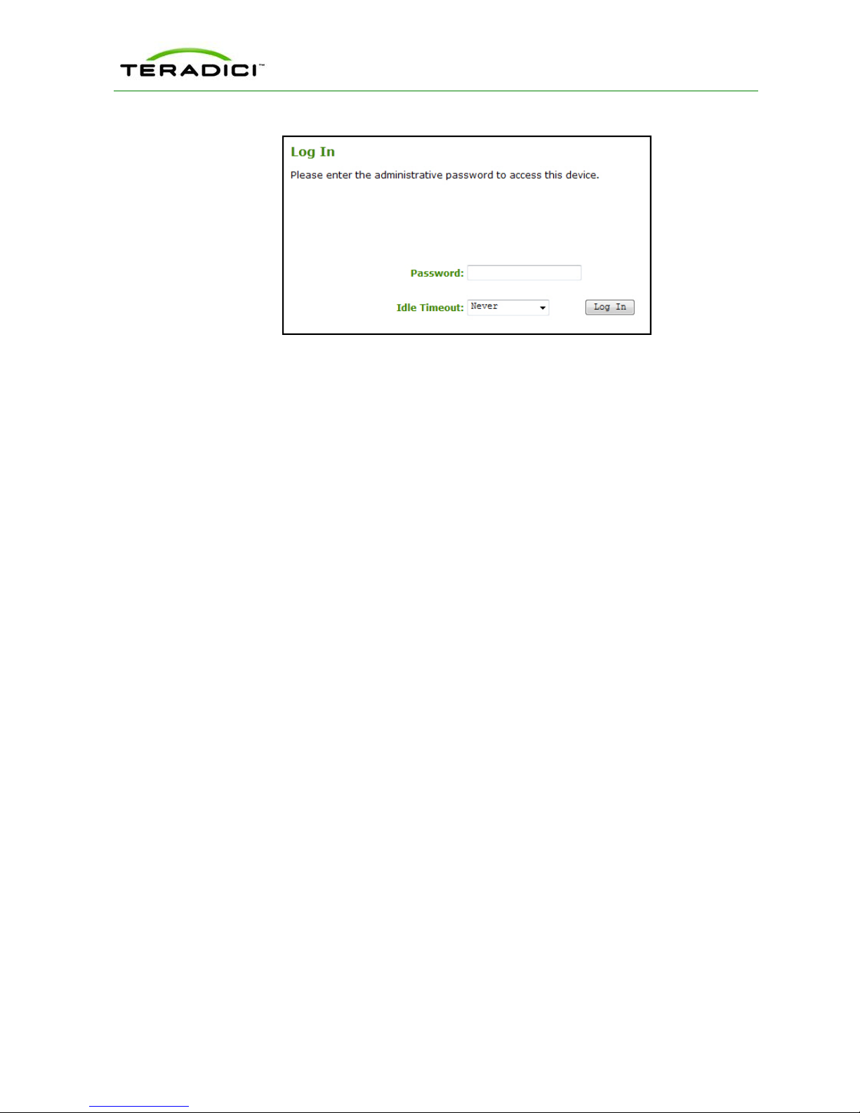
2.5 Logging In
To log into the Administrative Web Interface:
1. From the Log In page, enter your password. The default value is blank (i.e., "").
TER0606004 Issue 16 27
PCoIP Administrator's Guide
Figure 2-2: Administrative Web Interface Log In Page
2. To change the time after which the device is automatically logged off, set the Idle
Timeout field to:
l 1 minute
l 5 minutes
l 15 minutes
l 30 minutes
l Never
3. Click Log In. When you first login to a device, the Home Page appears. It provides an
overview of the device status. If configured in the firmware defaults, the Initial Setup
page appears the first time you log in.
Note: Some PCoIP devices have password protection disabled by default. You do not need a
password to login. You can enable or disable password protection for the Log In page using
the PCoIP Management Console. For details, see the PCoIP Management Console User
Manual (TER0812002).
If a warning message appears when you try to log in, then a session is already in progress
on that device. Only one user can log into a device at one time. When a new session logs in,
the current session is ended and the previous user is returned to the Log In page.
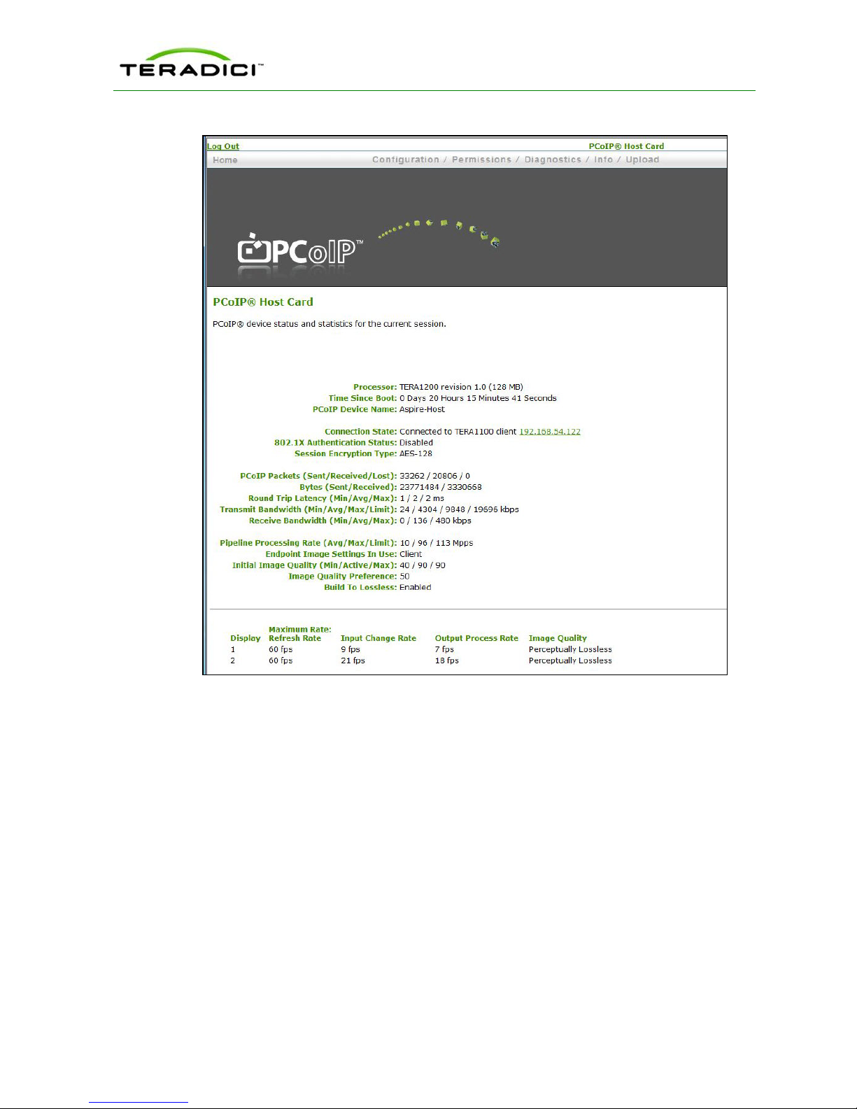
2.6 Viewing the Home Page
The Home page displays a summary of the host or client. The first time you log into the
Administrative Web Interface, the Initial Setup page appears. After you click Apply, the
Home page appears for each subsequent session. To display the Home page, click the
Home link at the top left section of the menu bar.
Note: When you click the Reset Statistics button, the statistics reported in the Home page
are also reset. For details about resetting the statistics, see section 6.3.
TER0606004 Issue 16 28
PCoIP Administrator's Guide
Figure 2-3: Administrative Web Interface Home Page (Host)
TER0606004 Issue 16 29
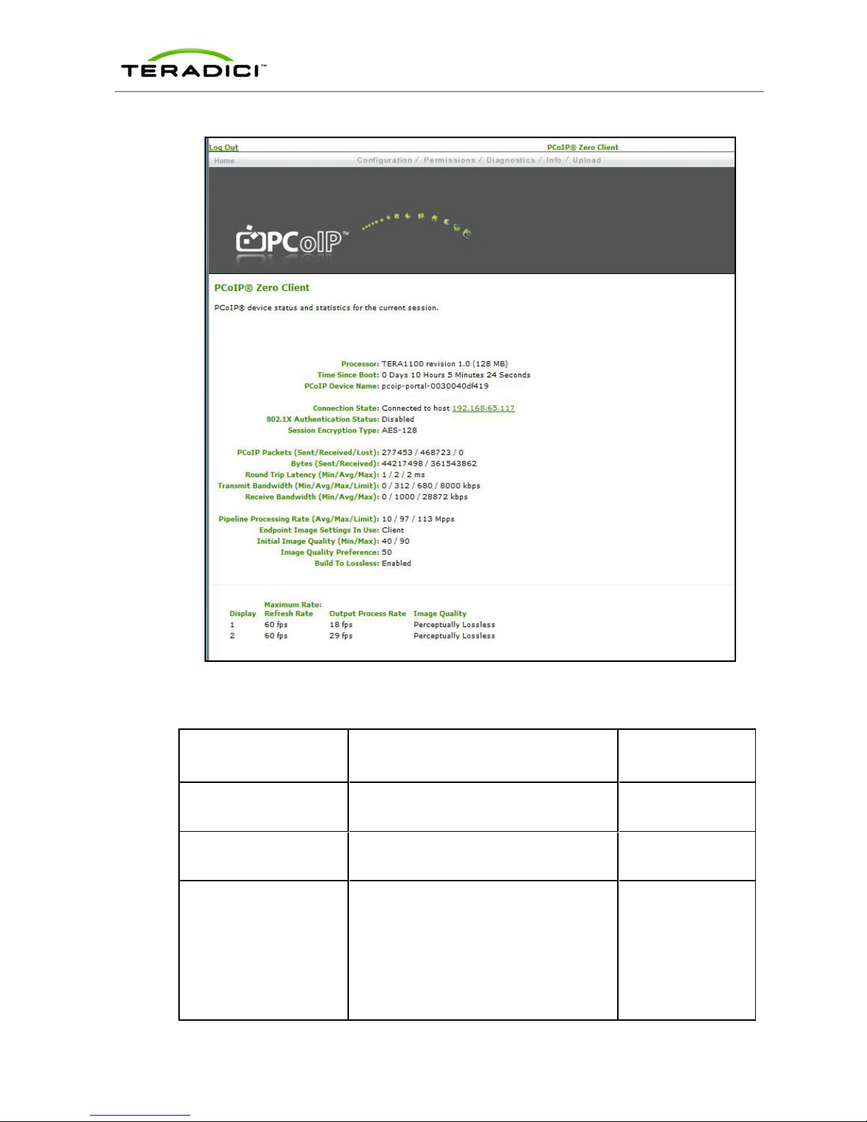
PCoIP Administrator's Guide
Figure 2-4: Administrative Web Interface Home Page (Client)
Table 2-1: Home Page Statistics
Statistics Description For Further
Details
Processor
Time Since Boot
PCoIP Device Name
TER0606004 Issue 16 30
PCoIP processor type, version, and RAM
size
Length of time that the PCoIP processor
has been running.
The logical name for the device.
This field is the name the host or client
registers with the DNS server if:
l DHCP is enabled
l the system is configured to support
registering the hostname with the DNS
server
N/A
See section 6.3
See section 4.4
 Loading...