

Page 1

ENC-200™ H.264 Encoder
User Guide V1.8
1
EENNCC--220000™
™
HH..22664
4
E
E
NNCCOODDEER
R
User Guide V1.8
Teracue GmbH
Schlossstr. 18
85235 Odelzhausen
Germany
Tel: +49 (0)8134-555-10
Fax: +49 (0)8134-555-199
[email protected]
www.teracue.com
Document Version 1.8/120327
Page 2

ENC-200™ H.264 Encoder
User Guide V1.8
2
C
OPYRIGHT
This document may not be reproduced in any form, in whole or in part, without
the prior permission of Teracue GmbH.
Copyright © 2014 by Teracue GmbH, all rights reserved.
D
ISCLAIMER
This publication supersedes all previous publications.
Information and specification in this documentation is subject to change
without notice. Please make sure you have the latest document version. User
guides are located at: www.teracue.com/support
If you find some points in this document unclear then please let us know, so
we can improve this documentation.
Thank you! Mail to: [email protected]
All information within this document is confidential to Teracue GmbH
costumers and should not be copied or distributed to non Teracue GmbH
customers.
T
RADEMARKS
ENC-200™ and all of its components are registered trademarks licensed to
Teracue GmbH.
All other logos and trademarks both marked and not, may be trademarks or
registered trademarks and therefore property of their respective owners.
Page 3

ENC-200™ H.264 Encoder
User Guide V1.8
3
I. Information about the manual
This document is designed to help users setup, configure and work with the H.264
encoders.
If you received this publication as a PDF, then it's a good idea to print it out for future reference.
It is best to use this user guide directly in front of your computer, by doing so you try out everything at
once.
.!. Important features are marked by this sign.
Page 4

ENC-200™ H.264 Encoder
User Guide V1.8
4
II. Release Notes
Following are the Features listed which are supported from the firmware versions:
Version 0.9.13 – 10/15/2009 10:54
Unicast and Multicast streaming is supported.
Support of PAL and NTSC.
CVBS Video Input is supported by using the breakout cable.
CVBS Video Input is supported by using the BNC interface on the front panel.
YC Video Input is supported.
SDI Video Input is supported by using the BNC interface on the front panel.
SDI embedded Audio is supported.
Analogue Audio Input with microphone level is supported.
Analogue Audio Input with line level is supported.
AES input is supported.
Transmission of H.264 SD (MPEG-4 part 10) streams is possible.
Deinterlacing is supported.
Simple firmware updating via web interface.
Real Time Clock (RTC) support.
DHCP Support.
Network settings are adjustable.
Overview of the ENC’s system environments displayed under ‘System’ menu, i.e. encoder
uptime, firmware version.
Support of the Factory-Reset feature via jumper.
Version 0.9.15 – 11/03/2009 08:51
Page refresh of the ENC web pages are supported
New default settings e.g.: IP 172.16.20.100, Destination IP 239.252.20.100.
XPlayer-Link added. For viewing and monitoring of the ENC-200 Stream. If the Standalone
XPlayer is installed on the client PC, running the web-config pages, the XPlayer can directly
be launched by a mouse click from the user interface.
Version 0.9.16 – 11/18/2009 12:36
Improvement of the NTSC support
Version 0.9.21 – 04/30/2010 11:06
COM server added.
GPIO function is added; GPIO Modes: Manual, Passthrough/A, Passthrough/B.
Added support for Status LED.
‘VideoLoss’ mode is added. Users can enable the ‘VideoLoss’ mode to stream a frame, when
the encoder loses the input video. (Only for analogue input)
Comport for RS-232 operation is supported and settings are adjustable via GUI.
New Comport Mode ‘Packet’ is added for a tunnelled data transmission with the compliance of
the temporal sequence.
New setting options in the encoder/audio settings menu: ‘Talkback Port’ and ‘Output Mute’.
Audio gain values are now set in dB values instead of percent values. (‘MicIn Gain’, ‘LineIn
Gain’, ‘Output Gain’)
Selectable network link mode.
New system status parameter added: ‘Mac Address’ and ‘Link Mode’.
Aspect ratio encoding option (4:3, 16:9, auto) is added.
New video codec from ingenient is used.
Version 0.9.22 – 06/16/2010 11:55
Adjustable resolution (Full D1, Half D1 and SIF/CIF) is added.
Improved talkback delay.
Page 5

ENC-200™ H.264 Encoder
User Guide V1.8
5
Version 0.9.25 – 08/05/2010 11:03
Full SNMP remote control added and MIB files. All settings can be remotely configured by 3rd
party SNMP manager.
SNMP status traps added
Support for AAC and MPEG1 audio.
Version 0.9.26 – 0.9.27 – Internal Versions
Version 0.9.28 – 01/28/2011 18:05
CBR Support; VBR and CBR are selectable on webpage.
Changeable source port number for MPEG transmission possible.
Video loss screen: support for SDI and new images BLACK and COLORBAR
Version 0.9.29 – 0.9.31 – Internal Versions
Version 0.9.32 – 04/04/2011 12:55
Support for TCP transmissions in connection with the DEC-200™
Restart encoding after errors, e.g. network problems
Add VBR low delay streamer
Add selectable sample rate for Talkback (48 kHz, 22.05 kHz)
Version 0.9.33 – 0.9.37 – Internal Versions
Version 0.9.38 – 01/12/2012 16:01
Added support for audio only streaming
Talkback: added support for upsampling
Enable Highpass filter for analog audio (AIC)
New session announcement attributes for SAP
Rename ts_mode to padding
Add config option for enabling/disabling config port 2323
Add new config option for transport rate
Add new config option for Video Encode-Mode (auto/progressive)
Add Factory Reset to web interface
Add interlaced to config option for Video Encode-Mode now (auto/progressive/interlaced)
Adjustable H.264 Profiles (Main / Baseline)
Version 0.9.39 – 02/17/2012 13:23
TS with padding: split H.264 packets on access unit boundaries
Bigger retry-interval to create a new connection via TCP
Change default setting (Encode Mode from Interlace > Auto, Padding = Off; TS-Rate = 0,
Video-Bitrate = 2000, Video-Deblocking = Auto)
Aspect ratio handling identical to ENC-300 (PAL D1 4:3 = 16:15, PAL D1 16:9 = 64:45, PAL
Half-D1 4:3 = 24:11, PAL Half-D1 16:9 = 32:11, PAL CIF 4:3 = 12:11, PAL CIF 16:9 = 16:11,
NTSC D1 4:3 = 8:9, NTSC D1 16:9 = 32:27, NTSC Half-D1 4:3 = 20:11, NTSC Half-D1 16:9 =
80:33, NTSC CIF 4:3 = 10:11, NTSC CIF 16:9 = 40:33)
Version 0.9.41 – 03/05/2012
snmp support for padding_overhead and 24 hour reset
add padding_overhead to web interface
support for 24 hour reset
Version 1.01 – 23/11/2012
Optimized TCP buffer/RTT settings
DHCP client sends hostname to server
KNOWN ISSUES:
Factory reset is not working when USB stick is plugged in
CBR Mode is not CBR again. Last good Version for CBR 0.9.41
Page 6

ENC-200™ H.264 Encoder
User Guide V1.8
6
III. Content
1. OVERVIEW ...................................................................................................................................... 7
2. GENERAL INFORMATION ............................................................................................................. 8
2.1 U
NPACKING THE ENCODER
......................................................................................................... 8
2.2 S
ETTING UP THE ENCODER AND SAFETY INSTRUCTIONS
.............................................................. 8
2.3 C
ONNECTING THE ENCODER
(FR-110
CHASSIS
) .......................................................................... 9
2.4 A
SSIGNMENT OF THE SUB-D
26-
PIN CONNECTOR
...................................................................... 10
2.5 B
REAKOUT CABLE
‘S’ ............................................................................................................... 11
2.6 B
REAKOUT CABLE
‘P’ ............................................................................................................... 12
3. ENC-200™ USER GUIDE ............................................................................................................. 13
3.1 A
CCESSING AND CONFIGURING ENCODERS
............................................................................... 13
3.2 L
OGIN
..................................................................................................................................... 14
3.3 G
RAPHICAL USER INTERFACE OF THE
ENC-200™ .................................................................... 15
3.3.1 Navigational Menus ........................................................................................................... 15
3.3.2 ‘APPLY’ and ‘SAVE’ Buttons ............................................................................................. 16
3.4 E
NCODER CONFIGURATION
...................................................................................................... 17
3.4.1 Menu: Encoder / Settings .................................................................................................. 17
3.4.2 Menu: Encoder / Video ...................................................................................................... 19
3.4.3 Menu: Encoder / Audio ...................................................................................................... 21
3.4.4 Menu: Encoder / SAP ........................................................................................................ 22
3.4.5 Menu: Encoder / Destination ............................................................................................. 23
3.4.1 Menu: Encoder / GPIO ...................................................................................................... 25
3.4.2 Menu: Encoder / XPlayer ................................................................................................... 27
3.4.3 Menu: Network / Settings .................................................................................................. 28
3.4.4 Menu: Network / SNMP (Simple Network Management Protocol) .................................... 29
3.4.4.1 Setting up the SNMP Manager ‘MIB Browser’ .......................................................... 31
3.4.5 Menu: Comport / Settings .................................................................................................. 34
3.4.6 Menu: System / Settings .................................................................................................... 36
3.4.7 Menu: System / Date/Time ................................................................................................ 37
3.4.8 Menu: System / Update (Upgrading firmware version) ..................................................... 38
3.4.9 Menu: System / Password ................................................................................................. 39
3.4.10 Menu: System / Remote ................................................................................................ 40
3.5 H
ELP
....................................................................................................................................... 41
3.6 L
OGOUT
.................................................................................................................................. 42
4. EXTENDED FUNCTION ................................................................................................................ 43
4.1 R
EMOTE CONTROL
.................................................................................................................. 43
4.2 A
UDIO TALKBACK
..................................................................................................................... 47
4.3 TCP S
TREAMING
..................................................................................................................... 49
4.3.1 TCP configuration when ENC-200™ is the Server ........................................................... 49
4.3.2 TCP configuration when DEC-200™ is the Server ........................................................... 50
4.4 R
ESETTING TO FACTORY DEFAULT
........................................................................................... 51
4.5 I
NPUT SIGNAL SWITCHING OF THE
BNC C
ONNECTOR ON THE FRONT PANEL
.............................. 52
4.6 R
ESTARTING THE
ENC-200™ .................................................................................................. 54
5. TECHNICAL SPECIFICATION ...................................................................................................... 55
6. KNOWN ISSUES ........................................................................................................................... 57
Page 7

ENC-200™ H.264 Encoder
User Guide V1.8
7
1. Overview
The ENC-200™ real-time encoder is designed for LIVE streaming applications such as LIVE TV or
video transmission, video trunking, IPTV encoding, remote monitoring feeds, video collaboration and
is also used as the ingest for LIVE and VOD video publishing systems.
Real-time LIVE streams from ENC-200™ encoders can be viewed on PC’s by using Teracue’s
XPlayer™ software player. TV’s, LCD’s, plasmas, monitors, can join the transmission streams with the
robust DEC-200™ decoder. Consumer and PC-based displays can cost-effectively receive ENC200™ streams with set top boxes.
To record and preserve LIVE feeds for later viewing, analysis or simply archiving the iCue™
Streaming Server has been designed.
ENC-200™ encoders incorporate low-latency compression technology and professional signal
processing, creating full resolution and smooth motion DVD-quality video streams.
Connect LAN Ethernet and a video/audio input signal and the ENC-200™ encoder will turn into a true
video networking ‘port’, transmitting your video in digital form over IP networks.
To access the intuitive graphical user interface use your standard web browser from any PC on the
network, no special or additional tools are required. Remote network configuration is also supported
over Telnet, as well as serial control over the local Comport.
All ENC-200™ process input streams in up to full DVD-quality for professional MPEG-4 AVC H.264
SD streaming to any kind of device. ENC-200™ encoders are built for robust 24/7 LIVE encoding
operations and can be used in tough environmental conditions. They are designed without any moving
parts, making them disk-, fan- and noiseless.
ENC-200™ combines high-performance with unparalleled simplicity in a compact Ethernet video
encoding appliance designed for commercial, institutional, and industrial applications such as:
Broadcast/TV Distribution over IP
IPTV/Confidence Monitoring
Security/Surveillance/Monitoring/Public Safety
Medical/Corporate/Military/Industrial-Training
Education/Distance Learning/Tele-Teaching
Finance/Brokerage Television
Legal/Legislative Communications
News/Sports/Advertising Agencies – Air/Rail station advertising
Manufacturing/Process Monitoring
Hospitals/Clinics/Telemedicine
The ENC-200™ blades are operated inside the FR chassis series. Blades can be used in the FR-110
single channel chassis or in the FR-210 dual channel chassis. High density requirements are solved
by operating the ENC blades in the FR-2000 multi-channel rack, which can hold up to max. 21
Teracue blades. Different types of ENC encoder blades, DEC decoder blades and DVB/IP video
gateways can be ‘mixed and matched’ inside the FR-2000 chassis.
Page 8

ENC-200™ H.264 Encoder
User Guide V1.8
8
2. General Information
You can operate the ENC-200™ blades in the FR-110 single blade chassis, in the FR-210 dual blade
chassis or in the FR-2000 multi-channel rack chassis. For example when only a small amount of
encoders is required, or if single channel encoders need to be set up at dispersed network locations.
All equipment (like the chassis) and ENC-200™ accessories are handled as model options and need
to be purchased separately.
2.1 Unpacking the Encoder
When you unpack the ordered equipment, please make sure that all the equipment is complete.
Normally the ENC-200™ blades are pre-fit into the according chassis that the encoders have been
ordered with.
If ENC-200™ blades are ordered and shipped separately, please be careful when handling the blades.
Be sure to avoid electrostatic influence when touching the blades.
After unpacking, your ENC-200™ should include the following:
1 x Teracue DVD which includes this user guide
1 x ENC-200™ H.264 Encoder blade
1 x Breakout cable ‘S’
2.2 Setting up the Encoder and Safety Instructions
Always read the instructions carefully and keep this user guide for future reference.
Please choose a suitable location for operating the encoder(s).
The ENC-200™ should not be exposed to the following:
Moist and dusty environments.
Air humidity above 80%.
Avoid extreme vibrations or shocks.
Direct sunlight and extreme heat.
Temperatures below 0°C and above +65°C.
Avoid quick and dramatic temperature changes.
.!. Please set up the encoder on a reliable and flat surface when using the FR-110/FR-210
chassis or mount in a rack, when using the FR-2000 chassis.
Page 9

ENC-200™ H.264 Encoder
User Guide V1.8
9
2.3 Connecting the Encoder (FR-110 chassis)
Please pay attention about the cabling order between the power supply and the FR-chassis. Connect
at first always the connector of the power supply to the FR-chassis.
The cable connector can be locked to the socket of the encoder, so the cable cannot accidentally be
pulled out [Bayonet Socket]. To do so the connector has to be placed on the socket and lightly turned
90° in a clockwise motion.
After you have connected the connector of the power supply to the chassis, please connect the power
cable to the power supply.
As next, please connect the network cable to the network interface and connect your video source unit
to the video input of the ENC-200™. Concerning of the video input you have the choice between
different video signal types. The ENC-200™ supports SDI (with embedded audio), Composite, SVideo, YPbPr signals. If you have a Composite (CVBS), S-Video (YC) or a YPbPr signal, please use the
Sub-D 26-pin connector via the breakout cable. If you have a SDI or Composite signal, please use the
BNC connector.
Furthermore, if you have analogue audio, please use the Sub-D 26-pin connector via breakout cable.
Figure 1: ENC-200™ front side
Front panel connection: Description:
Network: Standard 10/100Mbit/s Ethernet via RJ-45
USB: USB-interface.
Video Audio Comport GPIO:
Audio-, Video- and Data Output/Input for Composite, S-Video,
YPbPr, Audio-In, Audio-Out, GPIO, AES-In, RS-232, Genlock-In,
via Sub-D 26 pin interface.
Video:
Video Input for Composite or SDI (with embedded Audio) via
BNC interface.
LED:
LED status indicator. The LED indicates the status (operational
state) of the ENC-200 encoder. The status is indicated by the
LED colour and LED flashing (blinking) speed.
LED status: Description:
Constant green: OK, encoder in operation, encoding video.
Flashing green: OK, but video input signal is missing.
Flashing red: Network error. Encoder can not send data
packets.
Constant red: General error.
No LED light: Check power and power supply.
Power supply connector: Cable connector for the power supply.
Table 1: Description of the connectors on the ENC-200™ front side
CVBS = FBAS = Composite Signal
YC = S-Video Signal
Page 10

ENC-200™ H.264 Encoder
User Guide V1.8
10
2.4 Assignment of the Sub-D 26-pin Connector
Table 2 describes the Assignment of the Sub-D 26-pin connector which is on the front side of the
ENC-200™.
Pin: Sub-D 26-pin Connector Assignment:
1 AES 1 In
2 TxD
3 GPO
4 Audio In R
5 Audio Out R
6 Composite Sync Out**
7 Video In
Y
8 Video In
CVBS / Pr
9 Video In
C / P
b
10 GND
11 GND
12 GND
13 GND
14 GND
15 GND
16 GND
17 GND
18 GND
19 AES 2* In
20 RxD
21 GPI
22 Audio In L
23 Audio Out L
24 3V3 (See also chapter 6, page 57)
25 GND
26 Gen Lock In**
Table 2: Assignment of the Sub-D 26-pin Connector
CVBS = FBAS = Composite Signal
YC = S-Video Signal
* = Is not supported at the moment
** = Is not supported by the ENC-200
Page 11

ENC-200™ H.264 Encoder
User Guide V1.8
11
2.5 Breakout Cable ‘S’
For the ENC-200™ it exists two different breakout cables which are called Breakout cable ‘S’ and
Breakout cable ‘P’. The Breakout cable ‘S’ is the standard breakout cable and Table 3 describes the
provided signals.
Signal: Connector Type:
Audio In R + L 2 x Cinch (RCA)
Audio Out R + L 2 x Cinch (RCA)
Video CVBS Cinch (RCA)
Video YC Mini-DIN 4-pin (Hosiden)
Table 3: Breakout cable 'S'
Figure 2: Breakout cable 'S'
CVBS = FBAS = Composite Signal
YC = S-Video Signal
Page 12

ENC-200™ H.264 Encoder
User Guide V1.8
12
2.6 Breakout Cable ‘P’
For the ENC-200™ it exists two different breakout cables which are called Breakout cable ‘S’ and
Breakout cable ‘P’. The Breakout cable ‘P’ is the professional breakout cable and Table 4 describes
the provided signals.
Signal: Connector Type:
AES 1 BNC
AES 2* BNC
RS-232 Sub-D 9-pin
GPIO Sub-D 9-pin
Audio In R + L 2 x Cinch (RCA)
Audio Out R + L 2 x Cinch (RCA)
Video CVBS / YC / YPbP
r
3 x BNC
Table 4: Breakout cable 'P'
Figure 3: Breakout cable 'P'
CVBS = FBAS = Composite Signal
YC = S-Video Signal
* = Is not supported at the moment
** = Is not supported by the ENC-200
Page 13

ENC-200™ H.264 Encoder
User Guide V1.8
13
3. ENC-200™ User Guide
This chapter gives you an overview over ENC-200™ and demonstrates the encoder's main functions.
.!. Before proceeding please be sure that the encoder is setup correctly and all necessary
connections are established.
Working and configuring Teracue's encoders is very easy.
You do not need to install an application or remote configuring software. If you know how to browse
the internet, then you already know how to access and control the encoders, simply via web-browser.
3.1 Accessing and Configuring Encoders
Open your standard web-browser and enter the encoder's IP-address (e.g. ‘172.16.20.100’) in the
address field and press the ‘Enter’ button.
.!. If you haven't changed the factory presets and if not specified elsewhere in the
shipment the encoder's IP-address will by default be set to: 172.16.20.100.
Default IP-address:
172.16.20.100
Login username:
admin
Login password:
admin
.!. The encoder is configured by factory default to automatically start the encoding
process and streaming the video with the multicast address 239.252.20.100, when a
video is connected and a network link is established.
.!. To be able to login to the encoder's user interface, your computer has to be in the same
IP-address range (subnet).
.!. Lower firmware versions than the version 0.9.15 have another default IP-address,
please see therefor also chapter 6 on page 57.
You briefly might have to change your computers IP-address to be in the same subnet as the encoder.
Only then you will be able to access the encoder and change the encoder's IP-address, and of course
afterwards change your computer's IP-address back.
Page 14
ENC-200™ H.264 Encoder
User Guide V1.8
14
3.2 Login
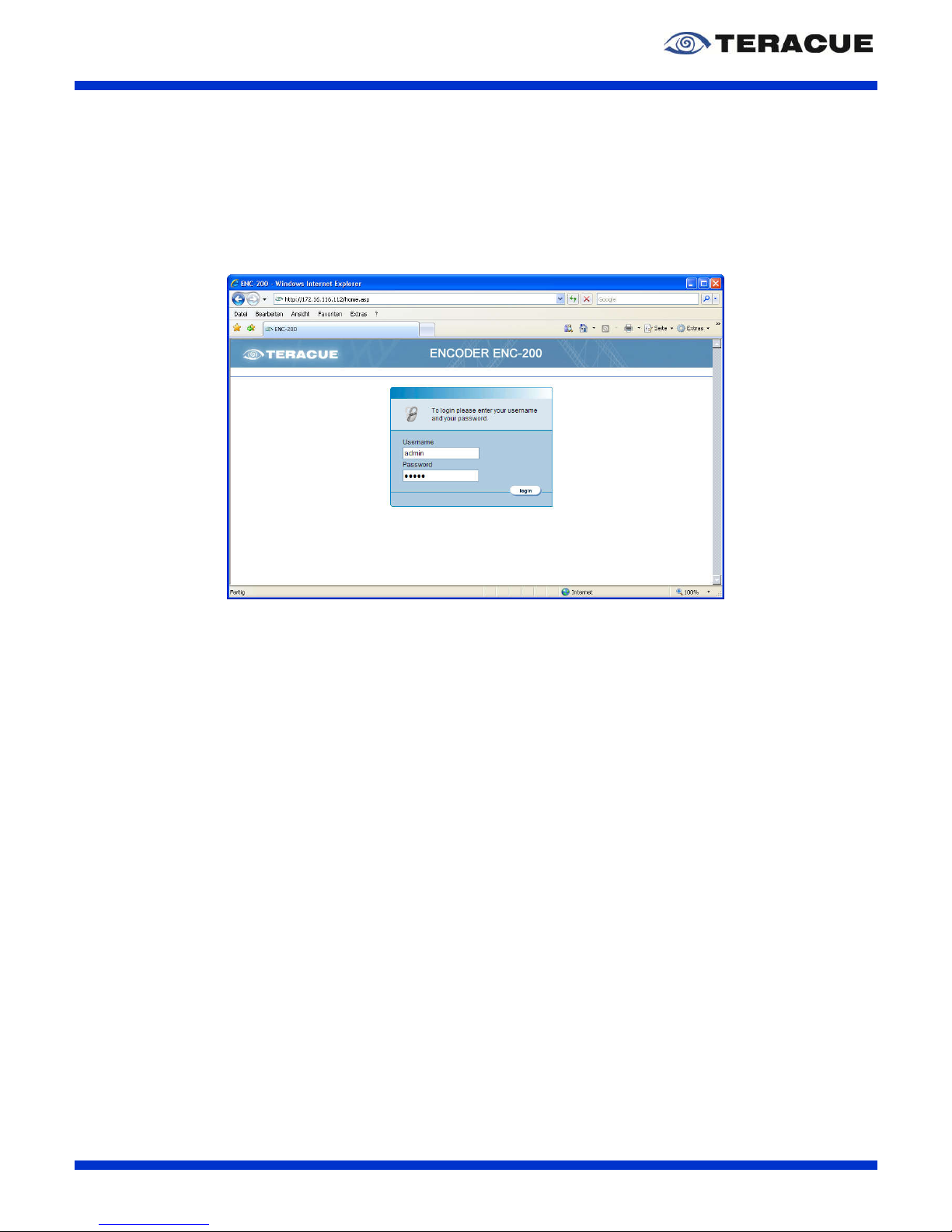
After typing the IP-address of your ENC-200™ into the browser and hitting enter, a login screen
should appear. See Figure 4.
Enter your username and password and click on ‘login’.
Figure 4: ENC-200™ web interface 'Login Page'
Default IP-address:
172.16.20.100
Login username:
admin
Login password:
admin
Page 15

ENC-200™ H.264 Encoder
User Guide V1.8
15
3.3 Graphical User Interface of the ENC-200™
3.3.1 Navigational Menus
After successful login you have access to the encoder's configuration. All of the settings can be
adjusted via web-browser.
Main Menu:
The main menu contains the ‘ENCODER’, ‘NETWORK’, ‘COMPORT’, ‘SYSTEM’, ‘HELP’ and
‘LOGOUT’ links from the top bar. See Figure 5.
Secondary Menu:
After selecting the desired menu item from the main menu, choose an area for configuration from the
secondary menu, which is resides on the left-hand side. See Figure 5.
Figure 5: Settings of the ENC-200™
Page 16

ENC-200™ H.264 Encoder
User Guide V1.8
16
3.3.2 ‘APPLY’ and ‘SAVE’ Buttons
A change or multiple changes of the configuration settings will only take effect
after the ‘> APPLY’ button is pressed.
The encoder will then start working with the new parameters, but the parameters
will not be saved to the encoder. Applied settings are not saved and will be lost
after a reboot.
Good for quickly testing and applying different settings.
Same as the ‘> APPLY’ button, but the configuration parameters will be applied
and saved to the encoders flash memory.
Saved parameters will be used by the encoder even when the encoder is turned
off & on or after a reboot has taken place.
Good for permanently saving the encoder configuration.
Page 17

ENC-200™ H.264 Encoder
User Guide V1.8
17
3.4 Encoder Configuration
3.4.1 Menu: Encoder / Settings
Under the menu option ‘ENCODER/SETTINGS’ you define the main operational state of the encoder.
Here you can set encoding process to ‘On’ or ‘Off’. See Figure 6.
Figure 6: 'Encoder / Settings' page of the ENC-200™ encoder
Settings: Description:
Page Refresh: Enables / Disables the refreshing of webpage every 10 seconds.
Encoder Start: Stops or starts the encoding process.
Stream Mode: Specifies the stream mode of the transmitted stream.
You can
choose between:
TS (Transport Stream)
TS/VIDEO (Transport Stream Video Only)
TS/AUDIO (Transport Stream Audio Only
VES (Video Elementary Stream)
AES (Audio Elementary Stream)
Padding: Specifies the padding mode. You can choose between:
ON (is recommend when a constant data rate is needed)
OFF (the transport stream has a variable data rate
. All
settings in the ‘VBV size’ field of the ‘video’ webpage have
no effects)
LOWDELAY (
the transport stream has a variable data
rate with enabled ‘Low Delay’ mode with the lowest delay.
A
ll settings in the ‘VBV size’ field of the ‘video’ webpage
have no effects.)
.!. ‘LOWDELAY’ will create non-ISO standard
TS
streams, but can reduce the delay.
To support
‘LOWDELAY’, the decoding side of your streaming
chain (i.e. decoder or STB) needs to be able to handle
the PTS and DTS codes as ISO/standard streams.
Page 18

ENC-200™ H.264 Encoder
User Guide V1.8
18
Transport Protocol: Specifies the transport protocol.
You can choose between the
connectionless protocol UDP and the connection-
oriented protocol
TCP. If you use TCP, your destination must also
support TCP.
Furthermore, no multicast is supported when using TCP.
If you
choose ‘TCP/SERVER’, your destination must be the client. If you
choose ‘TCP/CLIENT’, your destination must be the server.
For
more information, please see chapter 4.3 on page 49.
.!.
If network errors occur in your network, we
recommend using TCP protocol.
Transportrate [kbps, 0=auto]: Specifies the transport rate. The value ‘0’ indicates the automati
c
mode for the transport rate. The transport rate consis
ts of the
video bitrate, the audio bitrate and an overhead.
Please see also
Table 6.
.!. We recommend using the
value ‘0’ for the automatic
mode.
.!. Between the transport r
ate, the enabled padding
mode and the VBV buffer exists a closed relation
and their settings have an effect to the video.
Therefore we recommend the following:
Big transport rate value → Small VBV buffer value
Small transport rate value → Big VBV buffer value
VideoLoss: If the video input signal is lost, you can choose here a screen
which should streamed out. Following screens are available:
OFF
BLACK SCREEN
GREY SCREEN
COLORBAR
If ‘OFF’ is chosen, the encoder stops the streaming when the
video input is lost.
The ‘Video loss’ function is supported for SDI
signals and analogue video signals.
Input locked: Displays the status of input video (Read only)
. ‘YES’ indicates that
video input is OK. ‘No’ indicates that video input is missing.
Transportrate: Displays the actual stream transport rate when ‘ON’ as ‘Padding
’
is chosen. I.e. the network bandwidth of the stream.
(Read only
field)
Bytes Transmitted: Displays the number of Bytes that have been transmitted
. (Read
only field)
Table 5: Description of the ‘ENCODER/SETTINGS’ webpage of the ENC-200™
Transport Rate
measured in kbps:
Transport Rate
in kbps:
Video Bitrate
in kbps:
Intra Frame
Interval:
VBV Size
in msec.:
Audio Bitrate
in kbps:
2048 kbps 2067 1765 50 2500 96
1500 kbps 1500 1280 50 2500 64
1000 kbps 995 800 50 2500 64
Table 6: Example for possible transport rates
.!. Occurrence of errors at the ethernet connection: These errors are mostly a combination
of packet losses, permutations, bit errors, dalay / round-trip time, jitter etc. The
performance of the TCP error correction strongly depends on the round-trip time. If you
use TCP with a sendbuffer size of 250.000 and your round-trip time is not bigger than 60
msec., the ENC-200 absorbs packet losses of 3%. If you use TCP with a sendbuffer size
of 250.000 and your round-trip time is not bigger than 300 msec., the ENC-200 absorbs
packet losses of 1%.
Page 19

ENC-200™ H.264 Encoder
User Guide V1.8
19
3.4.2 Menu: Encoder / Video
Figure 7 shows the ‘Encoder / Video’ page of the ENC-200™ encoder and Table 7 describes it.
Figure 7: ‘Encoder / Video’ page of the ENC-200™ encoder
Settings: Description:
Codec: Displays the video codec of the output stream. (Read only)
Profile: Specifies the used H.264 profile. You can choose between:
Baseline
Main
Bitrate: Specifies the video bitrate in kBit/s of the output stream.
Intra Frame Interval: Specifies the interval of the intra frames. Intra frames (= I-Frames)
are total in
dependently coded frames which are used as
references frames.
Additional Information about P-Frames and GOP length:
At the ENC-200™ the data volume of a P-
Frame amounts
between 5% and 20% of an I-Frame.
If is assumed of an average
data volume of 10%, it means that for one I-Frame or ten PFrames the same data volume is needed.
The H.264 standard
allows long GOPs. The ENC-200™
limits the GOP length to 500
frames. More P-Frames at the same
data rate means also a better
quality. But more P-Frames have also tw
o disadvantages: 1) The
decoder can start the decoding process
not till then the decoder
get an I-Frame.
That means at a GOP of 500 frames, the decoder
waits in worst case 20 seconds before a picture can be displayed.
2) The result of this is also, that at occurrence
of network errors
(high packet loss), Frame gaps of up to 20 seconds can occur.
So,
the lower the P-
Frames, the higher are the robustness and the
faster can be switched the streams.
Deinterlacing: Enables / Disables deinterlacing.
Input: Specifies the video input which is available on the Sub-D 26-
pin
connector or on the BNC connector of the front panel.
SDI (via BNC on the front panel; note here chapter 4.5)
CVBS(BNC) (via BNC on the front panel; note chapter 4.5)
CVBS (via breakout cable)
Page 20

ENC-200™ H.264 Encoder
User Guide V1.8
20
YC (via breakout cable)
YPbPr (via breakout cable)
.!. Changes in this field require a reboot.
Format: Specifies the colour encoding system of the video input.
You can
choose between PAL and NTSC.
.!. Changes in this field require a reboot.
Aspect Ratio:
Specifies the aspect ratio. If an analogue input signal includes the
WSS (Wide Screen Signal) the encoder
can detect whether the
input signal is in 16:9 or in 4:3, when menu ‘Aspect Ratio’ is
switched to ‘AUTO’.
In the PAL standard video signal the wide
screen signal is included in the first half of line 23. In the NTSC
standard video signal the wide screen signal is included in the first
half of line 21. If your video source does not include the
WSS in its
analogue output signal, although you have a ’
16:9’ signal, you can
manually switch in this field the encoder to ’16:9’ or ‘4:3’.
Resolution: Specifies the video encoding resolution. You can choose between
full D1, half D1 and SIF/CIF resolution.
Full D1, Half D1 and
SIF/CIF streams can have a min. bandwidth of 500 kBit/s.
VBV size in ms: Specifies the input-
and output buffer of the encoder and decoder
and have an effect directly to the delay.
.!. We recommend a VBV buffer size of 2500 msec. H
ere
you are very safety.
.!.
For a small delay you can set the VBV buffer up to 800
msec.
, but when the video content is complex, it is
possible that a buffer overfl
ow occurs and because of
this the stream is faulty.
.!. Between the VBV buffer, the e
nabled padding
mode and the transport rate
exists a closed
connection and their settings have an effect to the
video. Therefore we recommend the following:
Big VBV buffer value → Small transport rate value
Small VBV buffer value → Big transport rate value
.!. This field have only an effect when padding is ‘ON’.
Deblocking:
Enables / Disables the deblocking function. You can choose
between:
AUTO
OFF
Encode Mode: Specifies the encoding mode. You can choose between:
AUTO (Decision via visual conten)
PROGRESSIVE
INTERLACED
Table 7: Description of the ‘ENCODER/VIDEO’ webpage of the ENC-200™
Page 21

ENC-200™ H.264 Encoder
User Guide V1.8
21
3.4.3 Menu: Encoder / Audio
Figure 8 shows the ‘Encoder / Audio’ page of the ENC-200™ encoder.
Figure 8: ‘Encoder / Audio’ page of the ENC-200™ encoder
Table 8 describes the ‘Encoder / Audio’ page of the ENC-200™.
Settings: Description:
Codec: Specifies the used audio codec of the transmitted stream. You
can choose between ‘AAC’ and ‘MPEG1’.
Bitrate: Specifies the audio bitrate in KBit/s of the transmitted stream.
Input: Specifies the audio input. You can choose between:
LINE (= Analogue audio with line level)
MIC (= Analogue audio with mic (microphone) level)
SDI (= SDI embedded audio)
AES
LineIn Gain: Specifies the line level gain of the analogue audio input.
MicIn Gain: Specifies the microphone level gain of the analogue audio input.
Output Gain: Specifies the output gain (Audio Out, Talkback). If the output
signal is too weak or too powerful, you can set here the output
gain level.
Output Mute: Mutes the audio output (Talkback).
Talkback Port: Specifies the port number of the talkback channel. For a talkback
session the encoder and the decoder must have the same
talkback port number.
Talkback Rate: Specifies the sample rate for the audio talkback function. The
sample rate which you select must be the same sample rate
which your decoder uses.
Table 8: Description of the ‘ENCODER/AUDIO’ webpage of the ENC-200™
Page 22
ENC-200™ H.264 Encoder
User Guide V1.8
22
3.4.4 Menu: Encoder / SAP
The Session Announcement Protocol (SAP) is a protocol for broadcasting multicast session
information. A SAP listening application can listen to the well-known SAP multicast address and
construct a guide of all advertised multicast sessions. SAP was published by the IETF as RFC 2974.
.!. According to this specification and standard SAPs are sent on the multicast address
224.2.127.254 on port 9875.
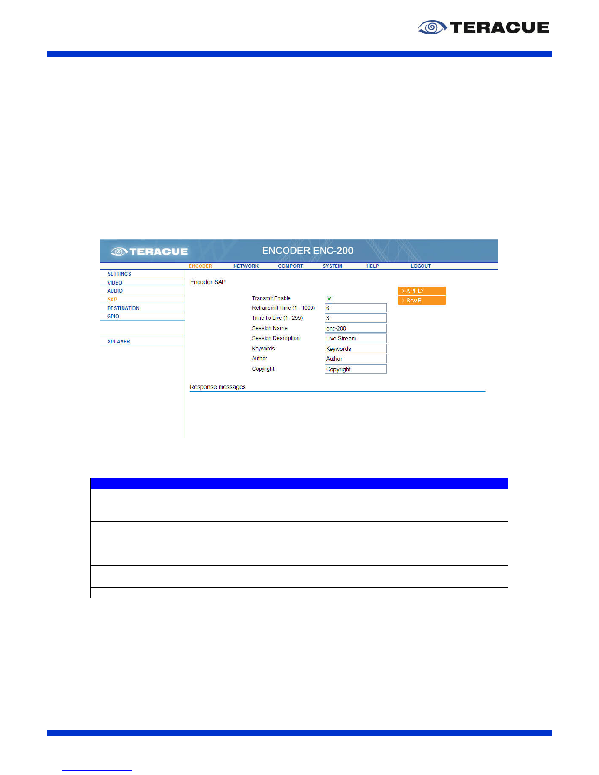
A SAP is used to label a stream to guarantee an effective workflow. Streams with SAPs can easily be
located, selected and viewed – due to their description. Please see the figure below to get an overview
of all the properties that can be defined.
Figure 9: ‘Encoder / SAP’ page of the ENC-200™ encoder
Table 9 describes the ‘Encoder / SAP’ page of the ENC-200™.
Settings: Description:
Transmit Enable: Enables/Disables the transfer of the SAP messages.
Retransmit Time: Specifies the time interval in seconds, how often the SAP
message shall be sent into the network.
Time To Live: Specifies the number of routers/switches how many
routers/switches a SAP message is allowed to travel/pass.
Session Name: Specifies the name for your session.
Session Description: Specifies the description of your session.
Keywords: Specifies your session with Keywords.
Author: Specifies the name of the author of the session.
Copyright: Specifies the description of the copyright of the session.
Table 9: Description of the ‘ENCODER/SAP’ webpage of the ENC-200™
Page 23

ENC-200™ H.264 Encoder
User Guide V1.8
23
3.4.5 Menu: Encoder / Destination
ENC-200™ is capable to encode a video either as a unicast stream or a multicast stream. According
to the entered destination IP-address, the encoder will automatically recognize whether it should be a
unicast or multicast stream.
Figure 10 shows the ‘Encoder / Destination’ page of the ENC-200™ encoder.
Figure 10: ‘Encoder / Destination’ page of the ENC-200™ encoder
Table 10 describes the ‘Encoder / Destination’ page of the ENC-200™.
Settings: Description:
Transport Protocol: Shows the used transport protocol, which can be changed in the
ENCODER > SETTINGS webpage of ENC-200™. (Read only)
IP address: Specifies the destination IP-address which should the ENC-200™
use for the encoded video.
If you want to stream a multicast stream:
Please enter in the ‘IP address’ field your desired multicast IP-
address, e. g. 239.252.20.100.
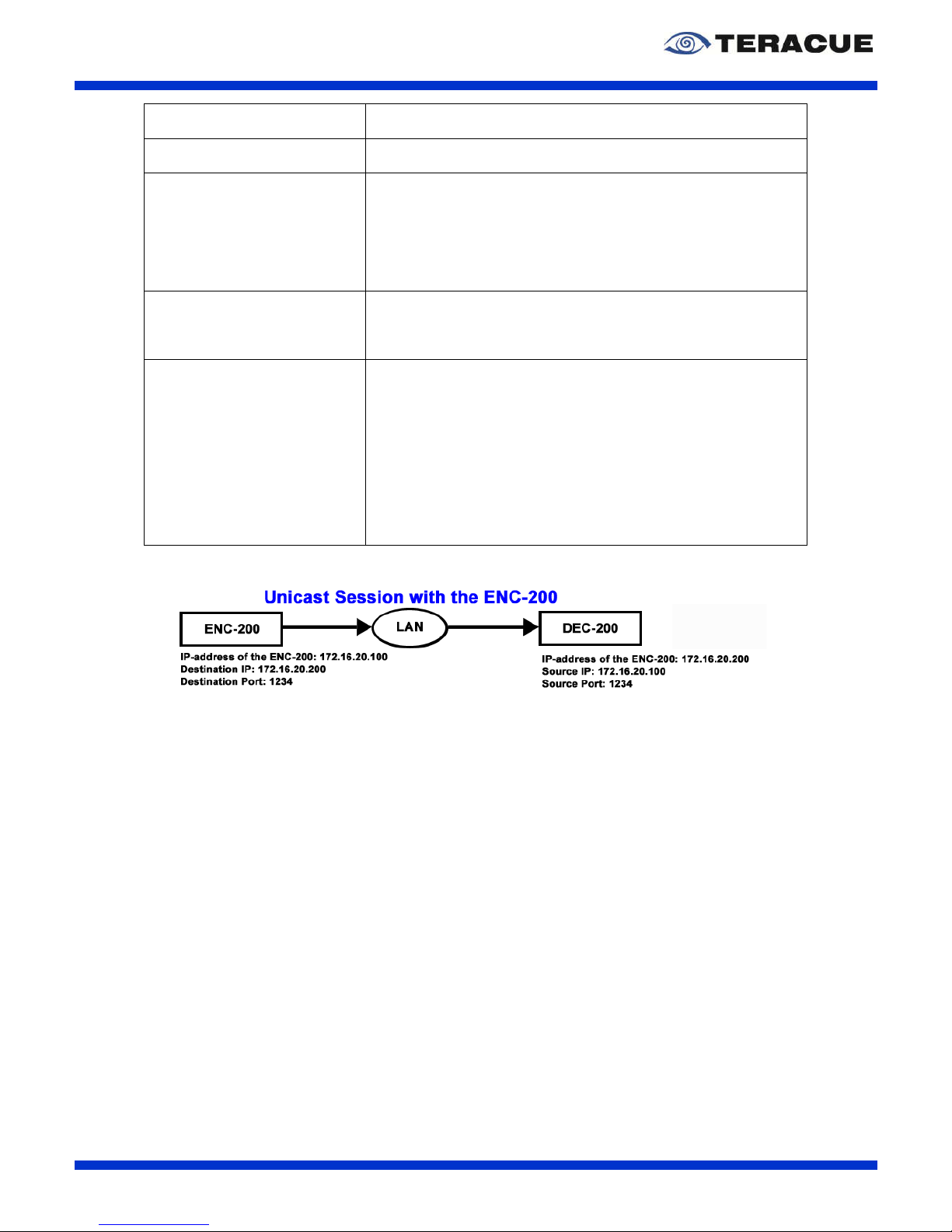
If you want to stream a unicast stream:
Enter in the ‘IP address’ field the IP-address of the destination, e.
g. the IP-address of the DEC-200™, see Figure 11.
Port: Specifies the port on which the encoder shall stream the video.
Enter in this field the port number which shall the stream has.
Source Port: Specifies the port number of the source in the UDP/TCP
datagram. You can set the source port to static port number
which is entered manually. Or you can set the source port to port
number which is set automatically by the encoder. As default the
source port is set to 9200. The automatically mode can be set by
entering the value ‘0’ in the text field and by confirming this entry
with the 'APPLY' button.
.!. If you change the ‘source port’ manually, please be
sure, that your entered port number is smaller than
1024 and higher than 9200, because in the range from
1024 and 9200 there are some reserved and used port
numbers. For example GPIO uses the port number
7778 and the comport 7777. Talkback uses the port
number 9177 and SNMP and SAP uses also reserved
port numbers.
Page 24
ENC-200™ H.264 Encoder
User Guide V1.8
24
Transmit Mode: Automatically set to unicast or multicast, depending on the
entered destination IP-address. (Read only)
TTL: Specifies the number of routers/switches how many
routers/switches the stream is allowed to travel/pass.
Join Own Multicast: If this check-box is enabled, the encoder sends IGMP-2 ‘join-
requests’ to routers/switches in order to keep the multicast port
open. Many network switches and routers (e.g. Cisco) support
IGMP-2 which close the port, when none is receiving the stream,
i.e. none is viewing a stream. By enabling this box the encoder
will act as if it is receiving a stream and keep the port open.
.!. We strongly recommend using this option.
Packet Size: Specifies the packet size in bytes. The packet size can be
changed in 188 byte steps. The range value goes from 1316 till
8836 bytes.
.!. We recommend using a packet size of 1316 Bytes.
Sendbuffer Size: The ‘Sendbuffer Size’ specifies how much TCP data are maximal
stored at the sender side (at the encoder side). The higher the
value, the more network problems can be absorbed, but the
higher is the delay at the decoder in error case. After an error
case, the delay decreases again. The delay increases only, if an
error occurs in the network. That means: If no network problems
occur, the delay does not increase, even though a high value is
set in the ‘Sendbuffer Size’ field. For more information, please
see chapter 4.3 on page 49.
.!. This field is only available when TCP is chosen as
transport protocol.
Table 10: Description of the 'ENCODER/DESTINATION' webpage of the ENC-200™
Figure 11: Unicast connection between ENC-200™ and DEC-200™
Page 25

ENC-200™ H.264 Encoder
User Guide V1.8
25
3.4.1 Menu: Encoder / GPIO
The General Purpose Input/Output (GPIO) supports a GPI function for the pass-through mode to
control devices which are connected with another ENC-200™ encoder or DEC-200™ decoder.
Furthermore it supports a GPO function for the manual mode to send a signal to a device which is
directly connected to the encoder via the GPIO D-Sub connector of the breakout cable ‘P’.
This allows users to connect a special device, e.g. sensor to the GPIO Port and send from the
encoder a signal to control the special device.
Figure 12: 'Encoder / GPIO' page of the ENC-200™ encoder
Settings: Description:
Mode: Specifies the GPIO mode. You can choose between ‘Manual’,
‘Passthrough/A’ and ‘Passthrough/B’.
‘Manual’ switches the local GPO value to the level high (=1) or
low (=0). The high or low level must be entered in the ‘GPO-
Value’ field.
‘Passthrough/A’ and ‘Passthrough/B’ forward the high (=1) or
low (=0) level via UDP to another encoder or decoder at which a
device is connected. Therefor the IP-address of the destination
encoder/decoder must be entered in the ‘Destination’ field. The
difference between ‘Passthrough/A’ and ‘Passthrough/B’ is that
the GPO value of ‘Passthrough/B’ is inverted. ‘Passthrough/A’
and ‘Passthrough/B’ has the following states:
Passthrough
Parameter:
ENC-200
GPI:
DEC-200
GPO:
RS422-200
OUT:
Passthrough/A
1 1 Relay Close
0 0 Relay Open
Passthrough/B
1 0 Relay Open
0 1 Relay Close
GPO-Value: Specifies the GPO high or low level. ‘0’ indicates the low level
and ‘1’ indicates the high level. This field is only in use, when the
mode is set to ‘Manual’.
Destination: Specifies the IP-address of the destination encoder/decoder to
which the high/low level shall be forwarded. This field is only in
use, when the mode is set to ‘Passthrough/A’ or ‘Passthrough/B’.
GPI-Value: Shows the high/low level which the encoder gets. Read only field.
Table 11: Description of the 'ENCODER/GPIO' webpage of the ENC-200™
Page 26

ENC-200™ H.264 Encoder
User Guide V1.8
26
The GPIO D-Sub Connector of the breakout cable ‘P’ has the following pin assignment.
Pin: GPIO Assignment:
1 NC
2 NC
3 NC
4 3.3V
5 GND
6 NC
7 GPO
8 GPI
9 NC
Table 12: Assignment of the GPIO Sub-D Connector of the Breakout Cable 'P'
.!. GPIO are TTL compatible. Furthermore the GPO output can tide maximum 24 mA.
Maximum current is 24 mA. The GPIO is temporary short-circuit-proof.
.!. The GPIO of the ENC-200 has TTL logic.
.!. IMPORTANT INFORMATION about ENC-200 board version ‘ENC200a.P3’:
The 3.3V output has no series resistor inside, but the
3.3V output has a safety fuse. The non-operating state of
GPI is 1. To change the GPI value to 0, you must set GPI to
GND. A series resistor is not needed at the ENC-200. The
non-operating state of GPO is 0 (= 0V, TTL = low). If GPO is
1 (TTL = high), the GPO has an output voltage of 5V. ENC 200 P2 boards which has yellow and green sticker at the board, are modified boards
and has the same GPI specifications like the ENC-200 P3 boards.
.!. IMPORTANT INFORMATION about ENC-200 board version ‘ENC200a.P2’:
The 3.3V output has a series resistor (1 kΩ) inside. The
non- operating state of GPI is 0. To change the GPI value to 1,
you must feed the GPI with 5V. A series resistor is not
needed at the ENC-200. The non-operating state of GPO is 0
(= 0V, TTL = low). If GPO is 1 (TTL = high), the GPO has an
output voltage of 5V. ENC-200 P2 boards which has yellow
and green sticker at the board, are modified boards and has the same GPI
specifications like the ENC-200 P3 boards.
.!. For an error-free GPIO operation in passthrough mode, both, the GPI source and the
GPO destination must be configured correctly. That means, the source and the
destination must be set to the identical passthrough mode, the correct IP-address of
the GPO destination must be entered in the source and the correct IP-address of the
GPI source must be entered in the destination. Furthermore, as long as the GPIO mode
is set to ‘Manual’ the GPI is blocked.
.!. The ENC-200 board version is directly printed at the ENC-200 serial number label.
NC = Not Connected
Page 27
ENC-200™ H.264 Encoder
User Guide V1.8
27
3.4.2 Menu: Encoder / XPlayer
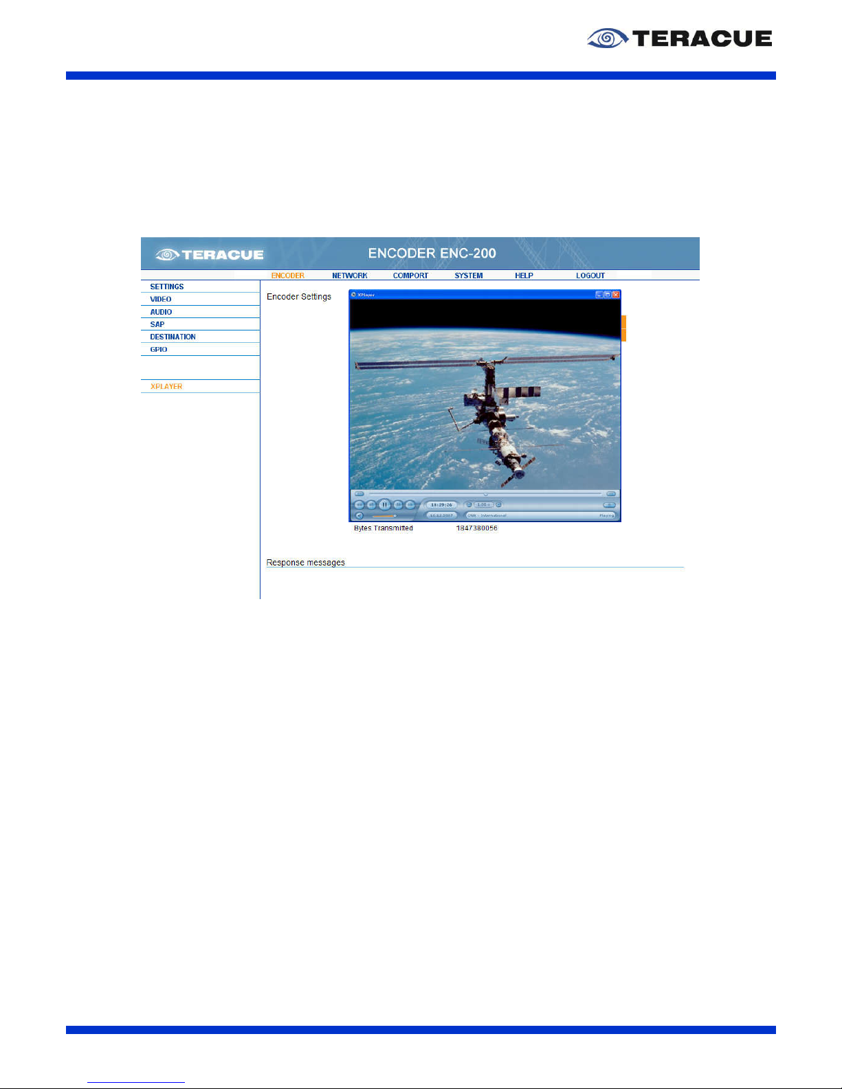
The menu ‘XPlayer’ starts the ‘Standalone XPlayer’, if an ‘XPlayer’ is installed on the client PC. You
can start the ‘XPlayer’ by clicking the XPlayer-Link inside the ‘Encoder’ menu.
Afterwards the ‘XPlayer’ automatically displays the stream of the ENC-200.
Figure 13: 'Encoder / XPlayer' page with opened XPlayer
If the XPlayer is not installed on the client PC, the XPlayer-Link will have no function.
.!. Requirement for this feature: The XPlayer must be installed.
Page 28
ENC-200™ H.264 Encoder
User Guide V1.8
28
3.4.3 Menu: Network / Settings
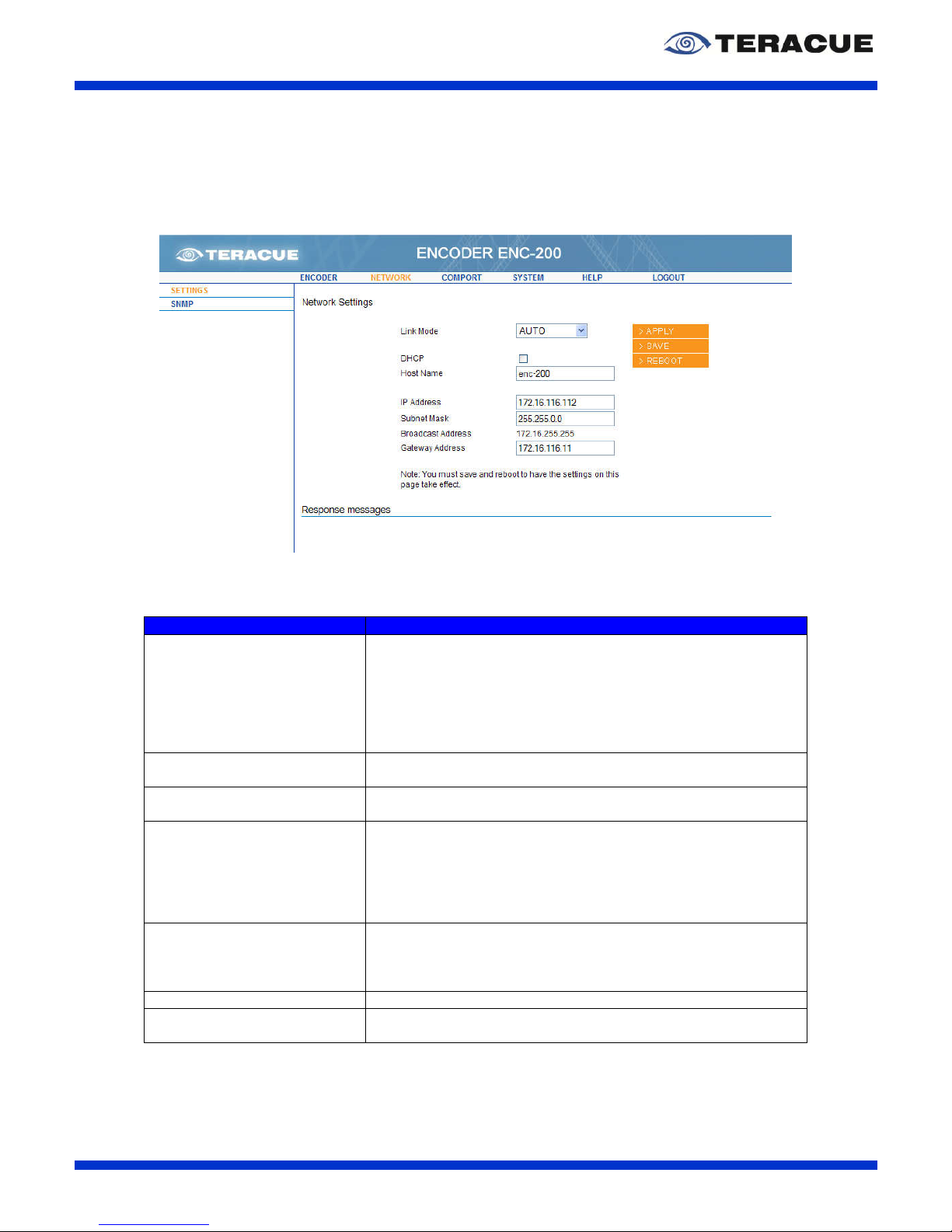
Figure 14 shows the ‘Network / Settings’ page of the ENC-200™ encoder. Here you are able to set the
encoder's own IP-address, subnet mask, gateway address and define the encoder's host name.
Figure 14: 'Network / Settings' page of the ENC-200™ encoder
Table 13 describes the ‘Network / Settings’ page of the ENC-200™.
Settings: Description:
Link Mode: Specifies the network port characteristics of the ENC-200™. This
option has been added especially to address specialized network
and/or administration requirements.
.!. In most cases it is sufficient (and recommended) to
leave this setting on ‘AUTO’, so the ENC-200™ and
the connected switch can deal out the preferred
connection on their own.
DHCP: Enables / Disables DHCP. Only use this option if you are familiar
with DCHP and your network supports DCHP.
Host Name: Specifies the hostname of the ENC-200™. Please enter your
desired hostname of the ENC-200™.
IP Address: Specifies the IP-address of the ENC-200™. The IP-address is an
identifier for your ENC in the TCP/IP network. Networks use the
TCP/IP protocol route messages based on the IP-address of the
destination. The format of an IP-address is a 32-bit numeric
address written as four numbers separated by periods. Each
number can range from 0 to 255. E.g.: 172.16.20.100
Subnet Mask: Specifies the subnet mask of the ENC-200™. A subnet mask is a
32-bitmask used to divide an IP-address into subnet and specify
the networks available hosts. E.g.: 255.255.0.0 is the net mask
for a class-B IP-address like 172.16.20.100.
Broadcast Address: Shows the framerate in fps of the received stream. (Read only)
Gateway Address: Defines IP-address of your gateway. The gateway is commonly
the address of the network device such as a network router.
Table 13: Description of the 'NETWORK/SETTINGS' webpage of the ENC-200™
.!. When the IP-address has been changed, the encoder needs to be reset (reboot), in
order for the new IP-address to take effect. When changing the IP-address please type
in the new IP-address, subnet mask, gateway-address and host name. Then hit the
‘SAVE’ button and then the ‘REBOOT’ button.
Page 29

ENC-200™ H.264 Encoder
User Guide V1.8
29
3.4.4 Menu: Network / SNMP (Simple Network Management
Protocol)
The Simple Network Management Protocol enables you to monitor and/or configure network attached
devices like the ENC-200™, made possible by the installed SNMP agents.
Every ENC-200™ since Firmware Version 0.9.23 is delivered with an SNMP agent. All you need are
the MIB (Management Information Base) files. W ith these MIB files you can use all advantages of
SNMP associated with the ENC-200™.
You can find the appropriate MIB files, ‘TERACUE-ENC200-MIB.txt’ and ‘TERACUE-SNMP-MIB.txt’
on the Teracue website IPTV Support Area. Or contact [email protected].
With these MIBs and a SNMP manager, you have the possibility, to monitor the ENC-200™ status (by
SNMP traps) or remotely configure every function of the ENC-200™ similar to the normal access via
your web browser. There are various SNMP management-tools available to issue SNMP based
commands to the appliance (Software not supplied by Teracue).
.!. Set your SNMP manager to SNMPv2.
Teracue uses the MIB Browser by iReasoning to monitor/set up the ENC-200™. iReasoning offers a
free version of the MIB Browser under www.ireasoning.com, which is useful to read the actual status
or setting up the ENC-200™. See further information about the MIB Browser of iReasoning in chapter
3.4.4.1 on page 31.
SNMP uses the following standard ports: Port 161 and port 162. Port 161 is used by the SNMP
manager and the agent to send the requests and their responses. Port 162 is used by the SNMP
agent to send TRAPs to the SNMP manager. Make sure that these ports are not blocked in your
network.
The following operations are possible with SNMP:
GET: Read out the management information.
GETNEXT: Read out the management information iteratively, this is useful when you want to read
the information down the MIB tree step by step.
GETBULK: Read out the management information of the complete list/tree.
SET: Change/set the management information.
TRAP: Start the Trap receiver in your SNMP manager to get alerts of the managed system.
E.g. the encoder was started / stopped.
To use the ENC-200™ SNMP features, you have to set up the encoder, to establish access with your
SNMP manager.
Page 30

ENC-200™ H.264 Encoder
User Guide V1.8
30
Figure 15: 'Network / SNMP' page of the ENC-200™ encoder
Settings: Description:
Manager IP: Specifies the IP-address of the Client PC on which the SNMP
manager (TRAP Receiver) is installed. This field must be
configured, to receive TRAPs.
GET community: Specifies the password for the GET community, which you must
enter in your SNMP manager in the Read Community field.
.!. We recommend leaving the default value ‘public’.
SET community: Specifies the password for the SET community, which you must
enter in your SNMP manager in the Write Community field.
.!. We recommend leaving the default value ‘private’.
TRAP community: The TRAP community describes a community string similar to the
GET and SET community string, but for Traps. The SNMP TRAP
server can find out whether the received TRAP message was
sent by an authorized client or not.
Location: Specifies the location of the SNMP-node in the network.
Contact: Specifies the name of the contact person/administrator who is
responsible for this device.
Name: Specifies the FQDN (Fully Qualified Domain Name) or the
hostname of the device.
Table 14: Description of the 'NETWORK/SNMP' webpage of the ENC-200™
The fields ‘Location’, ‘Contact’ and ‘Name’ describe the common SNMP-parameters (sysLocation,
sysContact and sysName) supported by every SNMP device. These details help you to find and
identify SNMP devices like the ENC-200™ in a network.
The SNMP elements use traps as SNMP base messages to report changes in status or alarm
conditions to remote SNMP management entities. Normally traps are used to alarm network
administrators of possible equipment problems or other important events. There are two types of
information sent by the trap device: ‘Events’ and ‘Alarms’.
‘Event’ traps will be sent if a monitored event occurs. These traps have only one state.
‘Alarm’ traps are events that have two states: Active and Clear. An ‘Active’ trap will be sent if an alarm
condition will be detected. The alarm will be kept active until the condition cleared and a ‘Clear’ trap
was send.
Page 31

ENC-200™ H.264 Encoder
User Guide V1.8
31
The ENC-200™ has the following trap alerts:
Trap Name: Description:
enc200VideoLockStatus: This trap is sent when the ‘Video locked’ status of the ENC-200™
has changed. The trap contains the new status variable (yes/no).
enc200EncodingStatus: This trap is sent when the ‘Encoding’ status of the ENC-200™
has changed. The trap contains the new status variable (yes/no).
enc200GpioStatus: This trap is sent when the ‘GPIO’ status of the ENC-200™ has
changed. The trap contains the new status value (1/0).
enc200DestIpChanged: This trap is sent when the ‘Destination IP-address’ of the ENC-
200™ has changed. The trap contains the new Destination IP-
address.
Table 15: Description of the ENC-200™ SNMP Traps
3.4.4.1 Setting up the SNMP Manager ‘MIB Browser’
To explain the use of SNMP, the following sites will give you a short overview of the possibilities you
have via SNMP. The SNMP manager will be explained with the SNMP-manager ‘MIB Browser’ by
iReasoning.
Open the ‘MIB Browser’ and load the MIB files. Click in den menu on ‘File’, select ‘Load MIB’ and
choose the folder with the MIB files, see Figure 16.
Figure 16: Load ENC-200™ MIBs
.!. You have to load both files: ‘TERACUE-ENC200-MIB.txt’ and ‘TERACUE-SNMP-MIB.txt’.
As next, go to the menu on ‘Tools’ and select ‘Options’. It opens the ‘Option’ window in which you
choose the ‘Agents’ tab please. See Figure 17.
Figure 17: 'Options' window of the MIB Browser
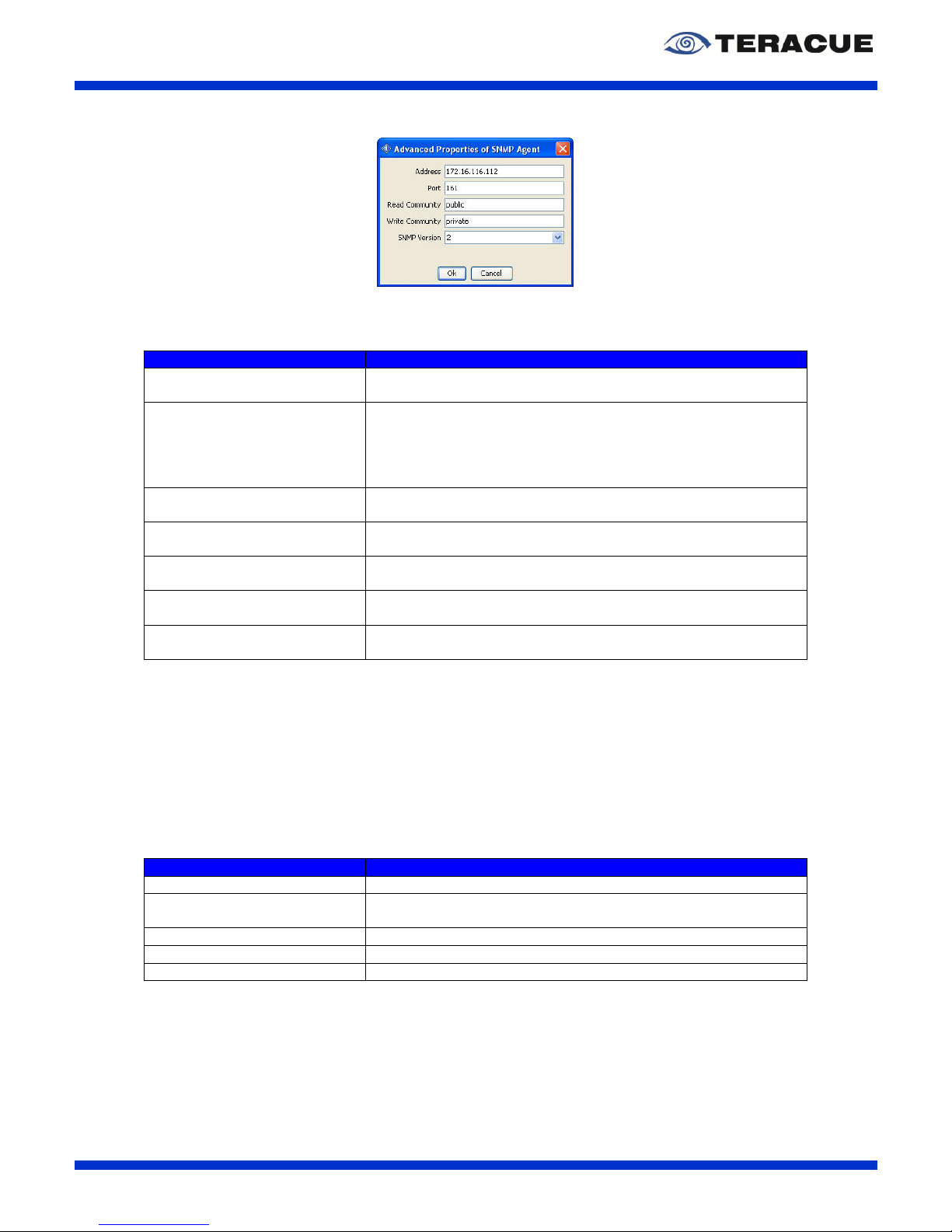
Click in the ‘Options’ window the ‘Add’ button. It opens the ‘Advanced Properties of SNMP Agent’
window to add a new SNMP device. See Figure 18.
Page 32
ENC-200™ H.264 Encoder
User Guide V1.8
32
Figure 18: 'Advanced Properties of SNMP Agent' window of the MIB Browser
Table 16 describes the ‘Advanced Properties of SNMP Agent’ window.
Settings and Buttons: Description:
Address: Specifies the IP-address of the SNMP device which should be
controlled. For example: The IP-address of the ENC-200™.
Port: The ‘Port’ field specifies the port number over which the MIB
Browser and the controlled device send the request and their
responses. The default port number is 161, which is defined by
the SNMP standard.
.!. We recommend not changing this port number.
Read Community: Specifies the ‘Read Community’ password. The default password
of the read community for the ENC-200™ is ‘public’.
Write Community: Specifies the ‘Write Community’ password. The default password
of the write community for the ENC-200™ is ‘private’.
SNMP Version: Specifies the supported SNMP version of the controlled device.
The ENC-200™ supports the SNMP Version 2.
Ok: Confirms your settings and creates an agent entry in the ‘Agent’
tab of the ‘Options’ window.
Cancel: Closes the ‘Advanced Properties of SNMP Agent’ window without
saving your settings.
Table 16: Description of the 'Advanced Properties of SNMP Agent' window
If you have created an agent entry in the ‘Options’ window, you can close the ‘Options’ window.
After you have loaded the ENC-200™ MIBs and have created an agent entry in the ‘Options’ window,
you are ready to control your ENC-200™ via SNMP.
To control your ENC-200™, please go to the data tree and open the loaded Teracue ENC-200™ MIB
which is shown there. The opened sub-tree shows you all the adjustable options, which you also have
with the ENC-200™ web interface. See Figure 19.
If you want to control the ENC-200™ via the MIB Browser, right-click at one data tree item, e. g.
‘videoBitrate’ and select your desired SNMP command (Table 17).
SNMP commands: Description:
Get: Read out the management information.
Get Next: Read out the management information iteratively, which is useful
if you want to read the information down the MIB tree step by step
Get Subtree: Read out the management information of the selected subtree.
Walk (Getbulk): Read out the management information of the complete list/tree.
Set: Change/set the management information
Table 17: Description of the SNMP commands
If you choose the SNMP command ‘Get’, the MIB Browser will show the actual setting of the selected
data tree item. E. g. in case of the selected ‘videoBitrate’ item: 3000 which stands for 3000 kBit/s.
If you choose the SNMP command ‘Set’, the ‘SNMP SET’ window appears in which you must enter
the new value of the selected data tree item. Choose in the ‘Data Type’ field the correct data type and
enter in the ‘Value’ field the new value, e.g. 2500. You find information about the needed data type in
the ‘Syntax’ field of the data tree item details which are shown in the left bottom of the MIB Browser.
See Figure 19.
Page 33

ENC-200™ H.264 Encoder
User Guide V1.8
33
Figure 19: Control the ENC-200™ via MIB Browser
The MIB-Browser shows you also details of your selected data tree item, see Figure 20. This info
section is in the left bottom of the MIB-Browser. Figure 20 shows the details of the data tree item
‘videoBitrate’. The syntax or rather the data type of the ‘videoBitrate’ item is an ‘Integer’ value between
250 and 4000. That means you can choose a video bitrate from 250kBit/s to 4000kBit/s. Furthermore
the info section of the data tree item ‘videoBitrate’ shows you that you have a read-write access. Table
18 describes the information section of the MIB Browser which is shown in Figure 20.
Figure 20: Details of the selected data tree item in the MIB Browser
Information Name: Description:
Name: This shows you the name of the selected data tree item.
OID: The Object Identifier (OID) is the explicit SNMP number of the
selected item/function.
MIB: This shows you the name of the MIB.
Syntax:
Integer:
Only entries of integer values are possible.
Integer32: Only entries of integer values with max 32 bit are
possible.
Octet String: Read-only/read-write numbers and characters (e.g.
Teracue) are allowed.
IPAddress: Read-only/read-write numbers in the IP address
string (e.g. 172.16.20.100) are allowed.
Access: The attribute ‘read-only’ or ‘read-write’ shows you whether you
can change the setting of the selected data tree item or whether
you just able to read out the actual setting or state.
Descr: This field gives you a short description of the selected data tree
item.
Table 18: Description of the information section of the MIB Browser
Page 34

ENC-200™ H.264 Encoder
User Guide V1.8
34
3.4.5 Menu: Comport / Settings
The ‘comport / settings’ webpage defines the parameters for the ENC's integrated comport/serial port.
ENC-200™ encoders are always comport servers and DEC-200 decoders are always comport clients.
Figure 21: 'Comport / Settings' page of the ENC-200™ encoder
Settings: Description:
Mode: Specifies the comport mode.
‘Console’ enables access and control of the ENC-200™
configuration via the com-cable (null modem cable). Use this
cable to set the ENC-200™ configuration when you do not want
to use web access.
‘Passthrough’ enables setting the comport to a serial mode. RS-
232 devices can be connected and controlled via the comport.
This is useful, for example when cameras or other non-IP, non-
network devices need to be remotely controlled. RS-232
commands can be tunnelled and sent via TCP/IP to the comport
server, where they will be returned into native RS-232
commands. When a connection is opened from the client (e.g.
decoder) to the IP-address of the encoder at port 7777, the serial
function in the ENC-200™ is activated and any data (string) is
passed straight to the connected RS-232 device. Once the
connection is established, this also works the other way for
information coming back from the RS-232 device.
‘Packet’ enables the packet mode. The ‘Packet’ mode enables
the tunnelled transmission of data with the compliance of the
temporal sequence. This mode is incompatible to other COM
Servers or Clients. That means the ‘Packet’ mode can only be
used between ENC-200™ encoders and DEC-200™ decoders.
At the ‘Packet’ mode the transmission is transparent and only the
parameters of the bitrate and the databits are set fix to 19200
bit/s, 8 databits. Data, which are sent as a block, shall be
outputted as a data block without gaps on the receiver side. Data
blocks, which are split with a gap, shall not be summarised on the
receiver side. Data blocks are sequenced signs with gaps which
are smaller than 4 Bytes.
Bitrate: Specifies the used bitrate in bits per second.
Databits: Specifies the databits. You can choose between ‘7’ and ‘8’.
Parity: Specifies the parity. You can choose between ‘none’, ‘odd’ and
Page 35

ENC-200™ H.264 Encoder
User Guide V1.8
35
‘even’.
Stopbits: Specifies the value of used stopbits. You can choose between ‘1’
and ‘2’.
Table 19: Description of the 'COMPORT/SETTINGS' webpage of the ENC-200™
Page 36

ENC-200™ H.264 Encoder
User Guide V1.8
36
3.4.6 Menu: System / Settings
The menu ‘System/Settings’ displays information about the firmware version that is installed on your
ENC-200™.
Furthermore the system uptime, the MAC address and the used link mode is shown in the
‘System/Settings’ menu. See Figure 22.
You can also make a factory reset via the ENC-200 webpage. Therefor it exist two possibilities:
Factory reset, without network settings. Therefor please click the ‘FACTORY RESET’ button.
Factory reset, including network settings. Therefor click the ‘FACTORY RESET ALL’ button.
Figure 22: 'System / Settings' page of the ENC-200™ encoder
Page 37

ENC-200™ H.264 Encoder
User Guide V1.8
37
3.4.7 Menu: System / Date/Time
You can set the time and date for the encoder in the menu ‘System/Date/Time’. See Figure 23.
Figure 23: 'System / Date/Time' page of the ENC-200™ encoder
Settings: Description:
Date (MM/DD/YYYY): Specifies the current date. Please enter the date in the following
syntax MM/DD/YYYY.
Time: Specifies the current time. Please enter the time in the following
syntax hh:mm.
Table 20: Description of the 'SYSTEM/DATE/TIME' webpage of the ENC-200™
Page 38

ENC-200™ H.264 Encoder
User Guide V1.8
38
3.4.8 Menu: System / Update (Upgrading firmware version)
Teracue's goal is customer satisfaction and constant product improvement. Please check regularly to
see if the most recent firmware version is installed on your ENC-200™. Please visit the IPTV Support
area on: www.teracue.com.
Firmware versions can be downloaded from the Teracue support website listed above. Firmware
versions have the suffix *.cpio.
Download the correct firmware version that you wish to update your encoders with and save it locally
on your computer.
Open the configuration webpage of the ENC-200™ and select the submenu ‘UPDATE’ within the
menu ‘SYSTEM’, see Figure 24.
Click on the ‘Browse’ button to locate the cpio-file on your local hard drive. Hit ‘OK’ and the path to the
file will be listed in the box in the middle of the screen.
To start the firmware update procedure simply click on the ‘send’ button.
After you have started the firmware update a hint website appears, that you shall not disconnect the
encoder from the network or power down the encoder. During the firmware update the encoding
process stops. Please wait till your web browser shows login screen from your encoder. If the login
screen appears, the update is finished and you can login to your encoder. It is no rebooting necessary.
The encoding process starts automatically after the firmware update is finished.
Figure 24: 'System / Update' page of the ENC-200™ encoder
.!. The update will not change your current settings.
.!. During update time do not disconnect the encoder from the network or the power.
Doing so will harm your encoder!
.!. Trying to connect to the encoder or navigating on the configuration webpages during
the updating process can also harm your encoder.
Page 39
ENC-200™ H.264 Encoder
User Guide V1.8
39
3.4.9 Menu: System / Password
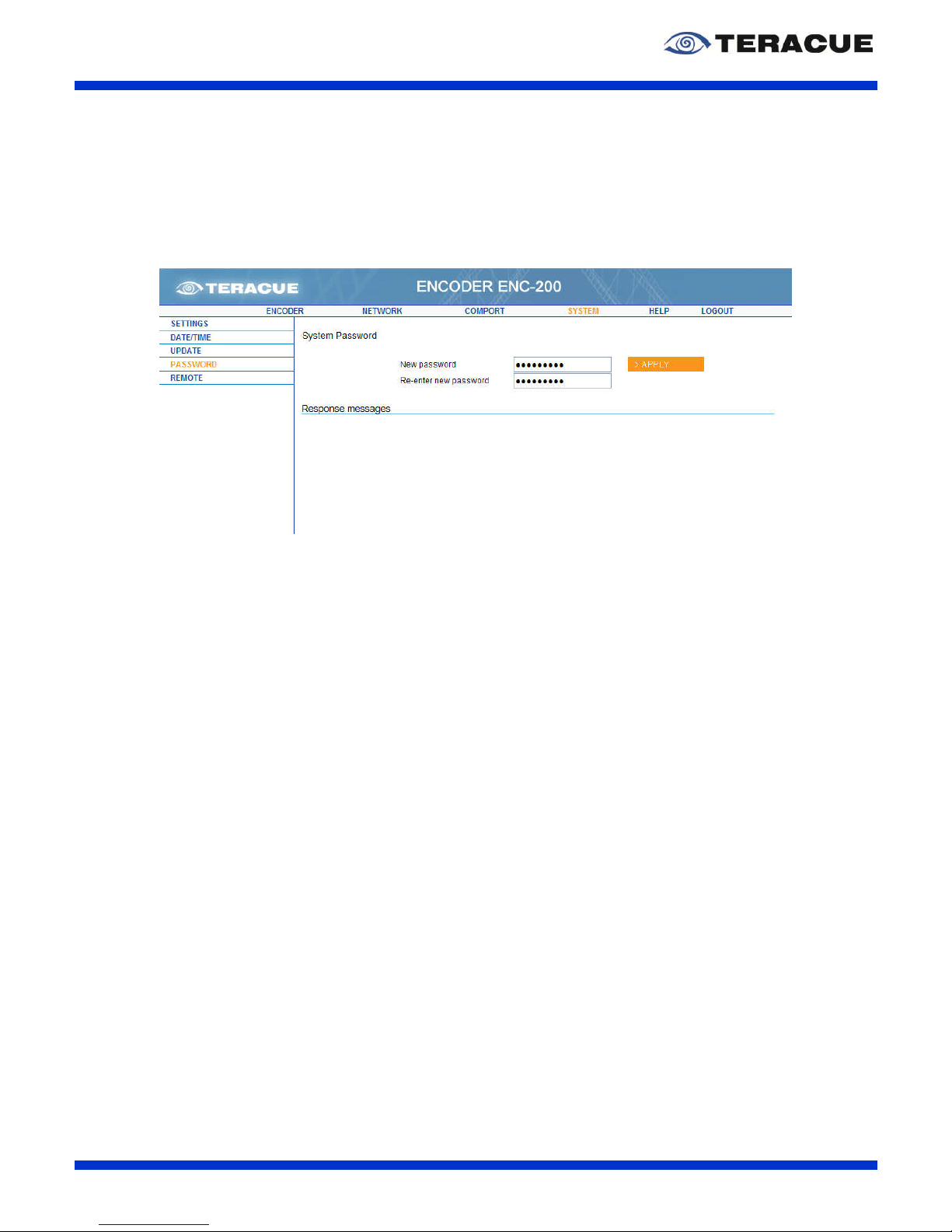
Figure 25 shows the ‘System / Password’ page of the ENC-200™ encoder.
If you do need to change the password due to security issues, then simply click on the submenu
‘PASSWORD’ and enter the new password twice in the provided boxes. Then hit the ‘APPLY’ button.
Figure 25: 'System / Password' page of the ENC-200™ encoder
.!. Unless your encoder is used in very critical scenarios, we recommend to leave the
password set to its default value (‘admin’, ‘admin’).
Page 40
ENC-200™ H.264 Encoder
User Guide V1.8
40
3.4.10 Menu: System / Remote
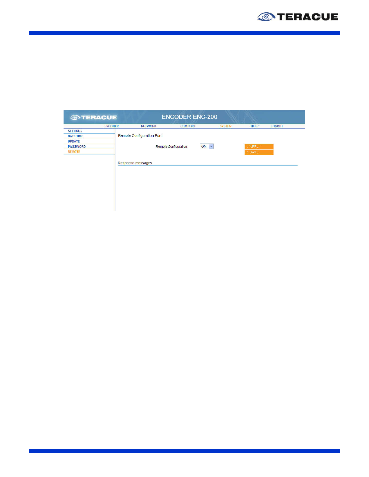
Figure 26 shows the ‘System / Remote’ page of the ENC-200™ encoder.
Enables / Disables the port 2323 for remote controlling. If you want use the remote control function,
you must enable the ‘Remote Configuration’ field. Then hit the ‘APPLY’ and ‘SAVE’ button. For more
information about remote control, please see chapter 4.1 on page 43.
Figure 26: 'System / Remote' page of the ENC-200™ encoder
Page 41

ENC-200™ H.264 Encoder
User Guide V1.8
41
3.5 Help
Clicking on the ‘HELP’ button will open the Teracue website where you can get to the ‘Support’ link.
.!. This will only work if the encoder is situated in a network in which internet access is
provided. Otherwise ‘page not found’ may be displayed.
Page 42

ENC-200™ H.264 Encoder
User Guide V1.8
42
3.6 Logout
After having made adjustments to the encoder, please be sure to logout, see Figure 27.
Figure 27: Logout form the ENC-200™
.!. Logging out prevents misuse and unauthorized access to the ENC-200™.
Page 43

ENC-200™ H.264 Encoder
User Guide V1.8
43
4. Extended Function
4.1 Remote Control
This chapter describes the remote control of the ENC-200™ for media controls like Crestron or AMX.
To control the ENC-200™, the telnet protocol is used at the port number 2323. Furthermore here is no
login necessary.
If you want to block the remote control via the port number 2323, you can disable the remote
configuration port 2323 via the webpage ‘System / Remote’ of the ENC-200™. See chapter 3.4.10.
To test the remote control under windows you can open the command prompt tool. A practical way to
open a command window within Windows Explorer is to write C:\Windows\system32\cmd.exe.
Another way to open a new commando prompt is by choosing the Start menu and selecting ‘Run’.
Then write ‘cmd’ in the text field and press the ‘OK’ button. See Figure 28.
Figure 28: Command to open the command prompt
In both cases the following window opens, see Figure 29.
Figure 29: 'Command Prompt' window to test the remote control of the ENC-200™
Page 44

ENC-200™ H.264 Encoder
User Guide V1.8
44
For starting a telnet session type: telnet <ip-address> <2323>, e.g. ‘telnet 172.16.20.100 2323’, and
press the Enter button. See Figure 30.
The value ‘2323’ specifies the used TCP/IP port number for the telnet session of the remote control
test. The IP-address should correspond to the ENC's IP-address.
Figure 30: Starting a telnet session for the remote control test
Figure 31: Session to test the remote control of the ENC-200™
After you have start the session, you got the display, see Figure 31: SDECRP
The command ‘help’ will display a list of all available options.
The ‘ls’ command allows you to see the available directories and options in the current directory.
To change the current directory, write ‘cd directory_name’, e.g. ‘cd status’. To go one directory layer
upstairs, enter the command ‘cd ..’. If you enter the command ‘exit’, the telnet session will close.
If you want to enter the value of an option you must use the ‘put’ command followed by the correct
values. Afterwards use the ‘apply’ and ‘save’ commands to apply and/or save your changes.
.!. Example:
E.g. for changing the destination IP-address, you need to type the following:
put /configuration/encoder/0/destination/ip_addr 239.252.20.100
apply /configuration/encoder/0/destination/ip_addr
save
.!. Figure 32 provides an overview over the telnet navigational and directory structure to
test the remote control. This overview is useful to find the correct configuration
settings when navigating in telnet mode. For instructions and descriptions on the
individual settings, please see the corresponding chapters for web based
configuration.
Page 45

ENC-200™ H.264 Encoder
User Guide V1.8
45
/
╠►
configuration/
║
╠═══════►
encoder/
║ ║ ╠════►
enable_config_port
Enable Config Port 2323 (yes, no)
║ ║ ╚════►
0/
║ ║
╠═════════►
page_refresh
Page Refresh (yes/no)
║ ║
╠═════════►
start
Encoder Start (yes/no)
║ ║
╠═════════►
stream_mode
Stream Mode (TS, TS/VIDEO, VES)
║ ║
╠═════════►
padding
Padding (on, off, lowdelay)
║ ║
╠═════════►
protocol
Protocol
║ ║
╠═════════►
videoloss
Video Loss Stream (GREY, OFF)
║ ║
╠═════════►
tsrate
Transport rate (0=auto)
║ ║
╠═════════►
video/
║ ║ ║ ╠════════►
format
Format (PAL/NTSC)
║ ║ ║ ╠════════►
bitrate
Bitrate in Bit/s
║ ║ ║ ╠════════►
intra_frame_interval
Intra Frame Interval
║ ║ ║ ╠════════►
deinterlacing
Deinterlacing (yes/no)
║ ║ ║ ╠════════►
input
V-Input (CVBS, SDI, Y/C, YPbPr)
║ ║ ║ ╠════════►
aspect_ratio
Aspect Ratio (auto, 4:3, 16:9)
║ ║ ║ ╠════════►
resolution
Resolution(full_d1, half_d1, sif/cif)
║ ║ ║ ╠════════►
profile
Profile (baseline, main)
║ ║ ║ ╠════════►
encode_vbr
Encoder VBR (yes, no)
║ ║ ║ ╠════════►
vbvsize_ms
VBV Buffer size in msec.
║ ║ ║ ╠════════►
deblocking
Deblocking (on, off, auto)
║ ║ ║ ╠════════►
encode_mode
Encode Mode
║ ║ ║ ╚════════►
tsrate_mode
TS-Rate M. (videorate, auto, user)
║ ║ ║
║ ║
╠═════════►
audio/
║ ║ ║ ╠════════►
codec
Audio Codec (AAC, MPEG1)
║ ║ ║ ╠════════►
bitrate
Audio Bitrate
║ ║ ║ ╠════════►
input
A-Input (LINE, MIC, ANC, AES)
║ ║ ║ ╠════════►
linein_gain
Line Level Gain
║ ║ ║ ╠════════►
micin_gain
Microphone Level Gain
║ ║ ║ ╠════════►
output_gain
Audio Output Gain
║ ║ ║ ╠════════►
output_mute
Audio Output Mute
║ ║ ║ ╠════════►
talkback_port
Talkback Port Number
║ ║ ║ ╚════════►
talkbace_rate
Talkback Sample Rate
║ ║ ║
║ ║
╠═════════►
sap/
║ ║ ║ ╠════════►
transmit
Transmit (on/off)
║ ║ ║ ╠════════►
retransmit_time
Retransmit time(1-1000)
║ ║ ║ ╠════════►
time_to_live
Time to live (1-255)
║ ║ ║ ╠════════►
session_name
Session name
║ ║ ║ ╠════════►
session_description
Session description
║ ║ ║ ╠════════►
keywords
Keywords
║ ║ ║ ╠════════►
author
Author
║ ║ ║ ╚════════►
copyright
Copyright
║ ║ ║
║ ║
╠═════════►
destination/
║ ║ ║ ╠════════►
ip_addr
Destination IP-address
║ ║ ║ ╠════════►
port Destination port number
║ ║ ║ ╠════════►
source_port
Source Port
║ ║ ║ ╠════════►
transmit_mode
Transmit mode; Read-only
║ ║ ║ ╠════════►
time_to_live
Time to live (1-255)
║ ║ ║ ╠════════►
join_own_multicast
Join own multicast (on/off)
║ ║ ║ ╠════════►
packet_size
Packet size
║ ║ ║ ╚════════►
sendbuf_size
Sendbuffer Size
║ ║ ║
║ ║
╚═════════►
gpio/
║ ║ ╠════════►
mode
GPIO Mode
║ ║ ╠════════►
gpovalue
GPO Value (0/1)
║ ║ ╚════════►
server
GPIO Destination IP-address
║ ║
║ ║
║ ║
║ ║
║ ║
║ ║
║ ║
║ ║
║ ║
║ ║
║ ║
║ ║
║ ║
Page 46

ENC-200™ H.264 Encoder
User Guide V1.8
46
║ ║
║ ║
║
╠═══════►
network/
║ ║ ╠════►
dhcp
DCHP (yes/no)
║ ║ ╠════►
ip_addr
ENC-200 IP-address
║ ║ ╠════►
subnet_mask
Subnet Mask
║ ║ ╠════►
broadcast_addr
Broadcast address; Read-only
║ ║ ╠════►
gateway_addr
Gateway address
║ ║ ╠════►
hostname
Hostname
║ ║ ╠════►
link_mode
Link Mode
║ ║ ╚════►
snmp/
║ ║
╠═════════►
manager
Manager IP-address
║ ║
╠═════════►
get_community
Get-Community password
║ ║
╠═════════►
set_community
Set-Community password
║ ║
╠═════════►
trap_community
Trap-Community password
║ ║
╠═════════►
location
Location of the SNMP device
║ ║
╠═════════►
contact
Contact person
║ ║
╚═════════►
name
SNMP device name
║ ║
║
╠═══════►
comport/
║ ║ ╠════►
mode
Comport mode
║ ║ ╠════►
bitrate
Bitrate
║ ║ ╠════►
databits
Databits (7/8)
║ ║ ╠════►
parity
Parity (none/odd/even)
║ ║ ╚════►
stopbits
Stopbits (1/2)
║ ║
║ ║
║
╚═══════►
system/
║ ╠════►
date Date; MM/DD/YYYY
║ ╚════►
time Time; HH:MM; 24hours
║
╚►
status/
╠═══════►
system/
║ ╠════►
board_version
ENC-200 Hardware Version
║ ╠════►
software_version
*
║ ╠════►
uptime
System uptime
║ ╠════►
arm ARM load (%)
║ ╠════►
dsp DSP load (%)
║ ╠════►
mac_address
MAC Address of the board
║ ╠════►
link_mode
Link Mode
║ ╠════►
date Date
║ ╚════►
time Time
║
╚═══════►
encoder/
╚════►
0/
╠═════════►
encoder_running
Encoder runs status; Read-only
╠═════════►
bytes_transmitted
Transmitted Bytes; Read-only
╠═════════►
transportrate
Transport rate in kpbs; Read-only
╠═════════►
input_locked
Video Input locked; Read-only
╚═════════►
gpio/
╚════════►
gpivalue
GPI Value; Read-only
Figure 32: Telnet directory structure for Remote Control testing
* = Is not supported at the moment
Page 47

ENC-200™ H.264 Encoder
User Guide V1.8
47
4.2 Audio Talkback
The audio output on the ENC-200™ operates as an audio decoder. It enables operating the ENC200™ in Full Duplex Audio. The ENC-200™ in connection with the DEC-200™ can therefore be used
for audio conferencing environments, where viewers of the encoded live streams are to be able to ask
questions and communicate with people on the encoding side. The default talkback port number of the
ENC-200™ is 9177.
For Example:
An encoder can be set up to encode video and audio from a camera that is installed at an entrance
(security application). The person who wants to enter speaks into a microphone to state his/her name,
etc. The microphone is connected to the audio input of the encoder. By using the decoder’s audio
input a receptionist/security officer is able to talk back to the person, e.g. arguing why access is denied
or that the person should hold its ID into the camera. This represents regular two-way communication
(Full Duplex Mode).
Another Example:
Students from classrooms or large auditoriums are communicating with doctors or surgeons inside of
operation rooms or other sealed environments. With the DEC-200's talkback option students or
monitoring staff are able to ask on the spot questions and communicate and learn in real-time.
To use the talkback function on the ENC-200™ in connection with the DEC-200™, please be sure that
your encoder has the firmware version 0.9.20 or higher, because this firmware is necessary for the
talkback function. Furthermore please be sure that your decoder has the firmware version 0.1.22 or
higher, because since this firmware version the talkback function is supported at the DEC-200™. If
your ENC-200™ encoder or DEC-200™ decoder does not have the noted firmware version, please
contact [email protected].
In order to talkback from the DEC-200™ to the ENC-200™, please be sure that you have a
microphone or another audio signal connected to the ‘Audio In’ input of your DEC-200™. Take also
care that loudspeakers are connected in the ‘Audio Out’ output of the ENC-200™ on which you want
talkback. See Figure 33. Figure 34 shows the talkback connection between DEC-200™ and ENC200™ in Full Duplex Mode.
Figure 33: Talkback connection between ENC-200™ and DEC-200™
Page 48
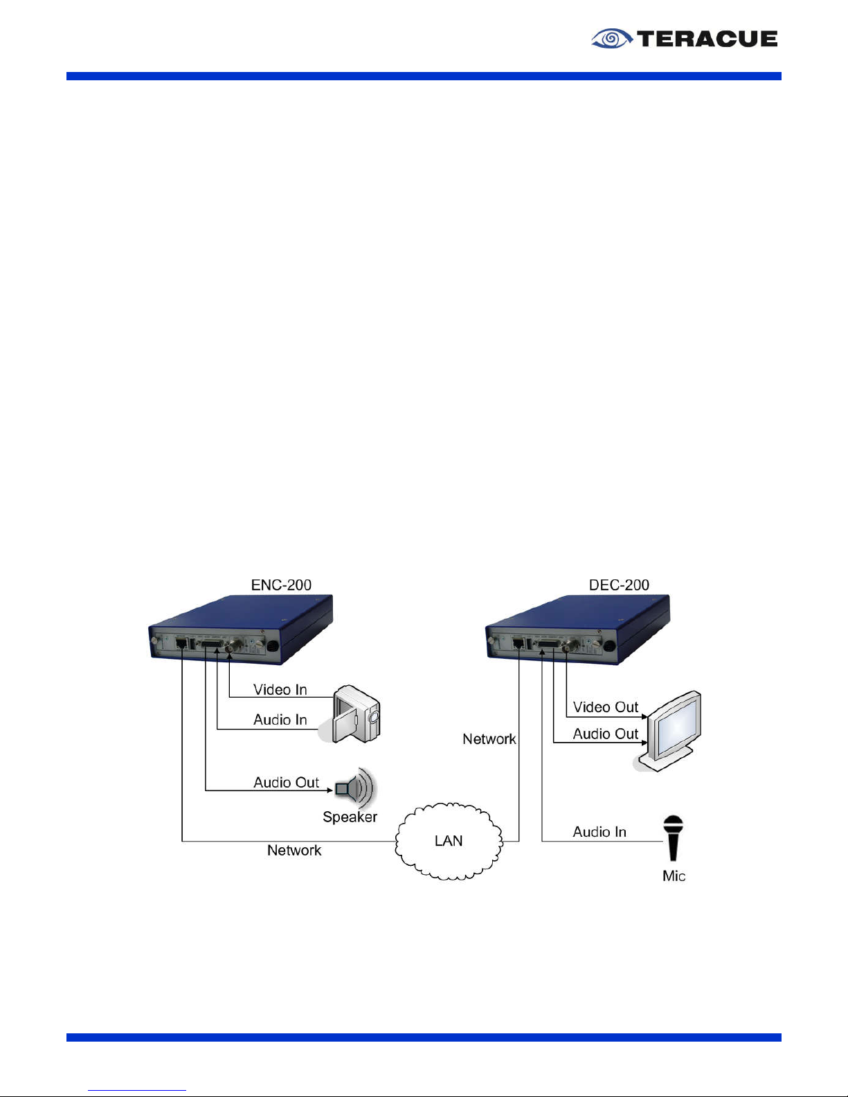
ENC-200™ H.264 Encoder
User Guide V1.8
48
For a talkback session you must configure the ENC-200™ encoder and the DEC-200™ decoder.
To start the talkback session you must configure the DEC-200™ webpage. Please open the DEC200™ webpage, select in the main menu ‘DECODER’ and click in the submenu ‘AUDIO’.
Enter in the ‘Talkback IP’ field of the DEC-200™ webpage the IP-address of the encoder with which
the DEC-200™ should start the talkback session. Next, the talkback port number must be entered in
the ‘Talkback Port’ field of the DEC-200™ webpage. So please enter in the ‘Talkback Port’ field of the
DEC-200™ your desired port number for the talkback session. This talkback port number must also be
set in the ENC-200™ webpage. Now, you must select in the field ‘Talkback Rate’ your desired sample
rate, which should be used from the decoder. The set talkback rate must also be set in the ENC-200™
webpage. Select in the drop-down-field ‘Audio Input’ of the DEC-200™ webpage the corresponding
audio input for the talkback function. For a detailed description of the decoder talkback settings,
please see the DEC-200™ user guide.
The DEC-200™ is totally configured for a talkback session now. As next you must configure the ENC200™ webpage. Therefor please open the ENC-200™ webpage, select in the main menu ‘ENCODER’
and click in the submenu ‘AUDIO’. See Figure 8 on page 21. Here you must enter the talkback port
number in the ‘Talkback Port’ field of the ENC-200™. The port number which you enter must be the
same port number which you have entered on the decoder side. Furthermore you must select in the
field ‘Talkback Rate’ the sample rate, which you have entered on the decoder side. The decoder and
the encoder must always use the same sample rate.
At the encoder side, you can also set the output gain level in the ‘Output Gain’ field and you can mute
the audio of the talkback session by enabling the ‘Output Mute’ check-box.
Now, the DEC-200™ and your desired ENC-200™ is completely configured and you can talkback
from the configured DEC-200™ to your configured ENC-200™.
To stop the talkback session, please enter ‘0.0.0.0’ in the ‘Talkback IP’ field of the DEC-200™.
Figure 34: Talkback connection between ENC-200™ and DEC-200™ in Full Duplex Mode
Page 49

ENC-200™ H.264 Encoder
User Guide V1.8
49
4.3 TCP Streaming
If in your network occurs packet loss, jitter etc., we recommend using the connection-oriented protocol
TCP. TCP provides a point-to-point connection (unicast) for applications that require reliable
communications. If the TCP connection is established, then the data will be streamed in the same
order as it was sent. Furthermore, lost packets can be retransmitted via TCP.
The ENC-200™ supports TCP streaming in connection with the DEC-200™. To use TCP streaming
on the ENC-200™ in connection with the DEC-200™, please be sure that your encoder has the
firmware version 0.9.29 or higher and your decoder has the firmware version 1.39 or higher, because
these firmware versions are necessary for TCP streaming.
TCP streaming is based on the client/server architecture. For TCP streaming with the ENC-200™ and
the DEC-200™ it exists to possibilities:
For TCP streaming you can configure the ENC-200™ as a server and the DEC-200™ as a
client.
For TCP streaming you can configure the ENC-200™ as a client and the DEC-200™ as a
server.
The ENC-200™ and DEC-200™ configuration changes depending on which client/server possibility
do you choose. So, the following subchapters describe the ENC-200™ and DEC-200™ configuration
for the two possibilities to make a TCP connection.
4.3.1 TCP configuration when ENC-200™ is the Server
Please make the following steps, to create a TCP connection at which the ENC-200™ is the server:
Please open the ENC-200™ webpage, go to the ENCODER > SETTINGS webpage and
select in the ‘Transport Protocol’ drop-down field the variable ‘TCP/SERVER’.
Go to the ENCODER > DESTINATION webpage of the ENC-200™ and enter a value in the
‘Sendbuffer Size’ field (e.g. 250000). The ‘Sendbuffer Size’ specifies how much TCP data
are maximal stored at the sender side (at the encoder side). The higher the value, the more
network problems can be absorbed, but the higher is the delay at the decoder in error case.
After an error case, the delay decreases again. The delay increases only, if an error occurs in
the network. That means: If no network problems occur, the delay does not increase, even
though a high value is set in the ‘Sendbuffer Size’ field.
Remain at the ENCODER > DESTINATION webpage of the ENC-200™ and enter in ‘Port’
field a port number which is not used in the network and which is not blocked (e. g. 1234).
Please open the DEC-200™ webpage, go to the DECODER > SOURCE webpage and select
in the ‘Transport Protocol’ drop-down field the variable ‘TCP/CLIENT’.
At the DECODER > SOURCE webpage of the DEC-200™, please enter in the ‘IP address’
field the IP-address of the ENC-200™ (e. g. 172.16.20.100). Note: TCP supports only unicast.
Remain at the DECODER > SOURCE webpage of the DEC-200™ and enter in the ‘Port
number’ field the same port number, which you have entered in the ENC-200™ (e.g. 1234).
Now the ENC-200™ and the DEC-200™ are configured for a TCP-connection.
Page 50

ENC-200™ H.264 Encoder
User Guide V1.8
50
4.3.2 TCP configuration when DEC-200™ is the Server
Please make the following steps, to create a TCP connection at which the DEC-200™ is the server:
Please open the ENC-200™ webpage, go to the ENCODER > SETTINGS webpage and
select in the ‘Transport Protocol’ drop-down field the variable ‘TCP/CLIENT’.
Go to the ENCODER > DESTINATION webpage of the ENC-200™ and enter in the ‘IP
address’ field the IP-address of the DEC-200™ (e. g. 172.16.20.200). Note: TCP supports
only unicast.
At the ENCODER > DESTINATION webpage of the ENC-200™, please enter in ‘Port’ field a
port number, which is not used in the network and which is not blocked (e. g. 1234).
Remain at the ENCODER > DESTINATION webpage of the ENC-200™ and enter a value in
the ‘Sendbuffer Size’ field (e.g. 250000). The ‘Sendbuffer Size’ specifies how much TCP data
are maximal stored at the sender side (at the encoder side). The higher the value, the more
network problems can be absorbed, but the higher is the delay at the decoder in error case.
After an error case, the delay decreases again. The delay increases only, if an error occurs in
the network. That means: If no network problems occur, the delay does not increase, even
though a high value is set in the ‘Sendbuffer Size’ field.
Please open the DEC-200™ webpage, go to the DECODER > SOURCE webpage and select
in the ‘Transport Protocol’ drop-down field the variable ‘TCP/SERVER’.
Remain at the DECODER > SOURCE webpage of the DEC-200™ and enter in the ‘Port
number’ field the same port number, which you have entered in the ENC-200™ (e.g. 1234).
Now the ENC-200™ and the DEC-200™ are configured for a TCP-connection.
Page 51

ENC-200™ H.264 Encoder
User Guide V1.8
51
4.4 Resetting to Factory Default
The ENC-200™ can easily be returned to its factory default values. In order to do these please power
down the encoder chassis and remove the blue top cover of the chassis. The Factory-Reset feature is
available as from the ENC-200™ firmware version 0.9.13. All ENC-200™ with the firmware version
0.9.13 has another default IP-address, please therefor note chapter 6).
Please execute the following steps to reset the ENC-200™ to the factory default settings:
Hold the opened chassis with the video input pointing to the left.
Locate the black pin connector and the jumper which is placed on the middle pin pair of the
black pin field.
Place the jumper now on the left pair of the black pins, see Figure 35
Turn the power on.
Wait for 2 minutes.
Power down the chassis. Return the jumper to its original position, i.e. onto the middle pin pair
of the black pin field.
Close the chassis with the blue top cover, connect the network cable and all audio/video
cables and turn the power on. All configuration settings except the network settings of your
encoder have been returned to its factory defaults.
Figure 35: ENC-200™ Blade of the Hardware Revision 2
Page 52

ENC-200™ H.264 Encoder
User Guide V1.8
52
4.5 Input Signal Switching of the BNC Connector on the
Front Panel
You have the possibility to change the signal type (Composite or SDI) for the video input at the BNC
connector on the front panel. This feature is implemented since the ENC-200™ firmware version
0.9.13. Therefor you must change the parameter of the video input on the ENC-200™ webpage and
you must put a mini-jumper to another pin position. If you hold the blade with the video input pointing
to the left, you can locate the mini-jumper at the top left corner of the blade, see Figure 36.
Figure 36: Mini-Jumper location for signal type switching at the BNC front panel output
For SDI input at the BNC connector on the front panel:
If the BNC connector of the front panel should be a SDI input, please place the mini-jumper in the
horizontal direction of the upper mini-pin pairs, based on the fact that the ENC-200 pointing with the
video input to the left, see Figure 37. For SDI input you must also change the video signal input
parameter on the ENC-200 webpage, please see chapter 3.4.2 on page 19.
For Composite input at the BNC connector on the front panel:
If the BNC connector of the front panel should be a COMP input, please place the mini-jumper in
vertical direction of the left mini-pin pairs, based on the fact that the ENC-200 pointing with the video
input to the left, see Figure 38. For Composite input you must also change the video signal input
parameter on the ENC-200 webpage, please see chapter 3.4.2 on page 19.
Figure 37: Mini-Jumper position for SDI input
Page 53

ENC-200™ H.264 Encoder
User Guide V1.8
53
Figure 38: Mini-Jumper position for CVBS input
Page 54

ENC-200™ H.264 Encoder
User Guide V1.8
54
4.6 Restarting the ENC-200™
If an ENC-200™ is not approachable anymore, you can restart the ENC-200™ by using the restart
switch. The restart button is placed in a hole on the front panel and it is located into the ‘O’ of the
lettering ‘NETWORK’, see Figure 39. To press the restart button, you need a long thin object with
which you can put it through the hole and with which you can press the restart button. After you have
pressed the button, the ENC-200™ restarts.
Figure 39: Restarting the ENC-200™ by using the restart button
Page 55

ENC-200™ H.264 Encoder
User Guide V1.8
55
5. Technical Specification
ENC-200™:
ENC-200™: H.264 SD encoder blade with analogue video input and SDI in
put,
embedded audio supported. The BNC connector on the front panel
can
be configured as Composite- or as SDI-input via jumper.
The ENC-200™ is delivered with the BREAK-
OUT cable S as standard.
Teracue also offers a professional BREAK-
OUT cable P which must be
ordered separately.
S – YC (MiniDIN), CVBS (RCA), Analogue Audio In (RCA), Analogue
Audio Out (RCA)
P – YPbPr, YC, CVBS, Genlock, AES-3id (BNC), Audio Out/In
(RCA), GPI In/Out (Sub-D 9pin), RS-232 (Sub-D 9pin)
Encoding Specifications:
Standards: PAL, NTSC
Video
Inputs: Composite: 1 VPP, 75 Ohm; Or S
DI Output: 0,8 VPP, 75 Ohm
(embedded audio support); This can be configured via jumper.
Break-out cable inputs: Composite: 1 VPP, 75 Ohm
S-Video: 1 VPP (Y), 0,3 VPP (C - Pal), 0,286 VPP (C - NTSC), 75 Ohm
Component: 1 VPP (Y), 0,7 VPP (PBPR) , 75 Ohm
Genlock: Blackburst 0,3 VPP, 75 Ohm
Video
Input Resolutions: Full D1: 720h x 480/576v, Half-D1: 352h x 480/5
76v, CIF/SIF: 360/384h x
288/240v, QCIF: 176h x 144/120v
Audio Inputs: Unbalanced Analog Stereo, Consumer Line level
AES-3id, 75 Ohm, 1 VPP, Unbalanced
Audio Outputs (Talkback): Analog Stereo, Consumer Line level
Video Codecs:
MPEG-4 AVC/H.264 (ISO/IEC 14496-
10), Main Profile at Level 3.1
(MP@L3), Baseline Profile at Level 3.1 (BP@L3), 4:2.0
Stream types: ISO/IEC 13818-1 Transport Streams
Elementary A/V
Audio Codecs: MPEG-4 AAC LC (ISO/IEC 14496-3)
MPEG-1 Audio Layer II (ISO/IEC ISO/IEC 11172-3)
I/O Specifications:
Network: 10/100TX Ethernet, RJ45, half/full duplex, Auto-sensing
Streaming traffic: Unicast and Multicast traffic supported
IP Protocols: HTTP (Web Browser), TCP/IP Control Protocol, UDP/IP
Streaming,
TCP/IP Streaming, IGMPv2/3, SNMP, RTP*, RTCP*, RTSP*, DHCP
RS-232 port: RS-
232 connection via console (Remote control for non IP devices via
TCP/IP RS-232 command tunnelling*)
GPI in*: 1 INPUT, (for device control: Streaming on/off configuration*)
GPI out: 1 OUTPUT, for switching peripheral devices on/off
Environmental:
Agency Approvals: CE, RoHS compliant
Humidity: Up to 90%, non-condensing
Temperature: 0 to +60°C environment temperature; fan less when operated in FR-
110
or FR-210 frames
Weight: Approx. 160 grams
Blade dimensions (H/W/D): 20mm x 130mm x 190mm
Power: 5W per blade
Limited Warranty: 1 year standard limited warranty. Warranty extensions available
Page 56

ENC-200™ H.264 Encoder
User Guide V1.8
56
Chassis:
FR-110: Single channel chassis, 5V DC, 10W, 100-
240V AC ext. power supply
included; Dim
ensions (H/W/D): 45mm x 145mm x 240mm, Weight: 650
grams; No forced cooling required (fan less)
FR-210: Dual channel chassis, 5V DC, 10W, 100-
240V AC ext. power supply
included; Dimensions (H/W/D): 70mm x 145mm x 240mm, Weight: 650
grams; No forced cooling required (fan less)
FR-610: Multichannel chassis with cooling fans; holds max. 6 ENC/DEC blades;
Two redundant power supply modules: Max. 70W with 6 blades, 100240V AC;
Dimension (H/W/D): 45(1RU) x 485 x 395 mm, Weight: 4,35 kg
(empty)
FR-2000-24: High-density, multichannel chassis; holds max. 21 ENC/DEC
blades,
Max. 150W with 21 blades, 90-
240V AC internal DUAL, REDUNDANT
power supply with cooling fan.
Dimension (H/W/D): 176(4RU) x 480 x 400
mm, Weight: 9,5 kg (empty)
FR-PLATE-1/3: FR-2000-24 / FR-610 covering plate for empty slots: ‘FR-PLATE-1’
covers
1 slot; ‘FR-PLATE-3’ covers 3 slots.
Page 57

ENC-200™ H.264 Encoder
User Guide V1.8
57
6. Known Issues
Factory reset is not working when USB stick is plugged in
CBR Mode is only working until firmware version 0.9.41
The ENC-200™ firmware versions till version 0.9.13 have the default IP-address
172.16.20.201.
A range of ENC-200™ have the +3.3 V at Pin 24 which is protected with a 1k resistor. The
listed serial numbers below specifies the ENC-200™ with this resistor. At these encoder
boards, the +3.3 V can not be used as a supply voltage. At all other ENC-200™, which are not
listed here, the auxiliary supply can be used as a fused supply voltage with max. 500mA
current.
S/N: 2MK/0938/103 - 2MK/0938/115
S/N: 2MK/0938/117
S/N: 2MK/0938/119 - 2MK/0938/140
S/N: 2MK/0938/142 - 2MK/0938/154
S/N: 2MK/0938/156 - 2MK/0938/175
S/N: 2MK/0938/177 - 2MK/0938/203
S/N: 2MK/0938/205 - 2MK/0938/221
S/N: 2MK/0938/225
S/N: 2MK/0938/227
S/N: 2MK/0938/232
S/N: 2MK/0938/233
S/N: 2MK/0938/235 - 2MK/0938/248
S/N: 2MK/0938/252
S/N: 2MK/0938/254 - 2MK/0938/255
S/N: 2MK/0938/262 - 2MK/0938/267
S/N: 2MK/0938/269 - 2MK/0938/284
S/N: 2MK/0938/298 - 2MK/0938/299
Page 58

ENC-200™ H.264 Encoder
User Guide V1.8
58
IV. List of figures
F
IGURE 1:
ENC-200™
FRONT SIDE
............................................................................................................ 9
F
IGURE 2: BREAKOUT CABLE
'S' ............................................................................................................... 11
F
IGURE 3: BREAKOUT CABLE
'P' ............................................................................................................... 12
F
IGURE 4:
ENC-200™
WEB INTERFACE 'LOGIN PAGE
' ............................................................................... 14
F
IGURE 5: SETTINGS OF THE
ENC-200™ ................................................................................................. 15
F
IGURE 6: 'ENCODER / SETTINGS' PAGE OF THE
ENC-200™
ENCODER
...................................................... 17
F
IGURE 7: ‘ENCODER / VIDEO’ PAGE OF THE
ENC-200™
ENCODER
........................................................... 19
F
IGURE 8: ‘ENCODER / AUDIO’ PAGE OF THE
ENC-200™
ENCODER
........................................................... 21
F
IGURE 9: ‘ENCODER /
SAP’
PAGE OF THE
ENC-200™
ENCODER
............................................................. 22
F
IGURE
10: ‘E
NCODER / DESTINATION’ PAGE OF THE
ENC-200™
ENCODER
............................................... 23
F
IGURE
11: U
NICAST CONNECTION BETWEEN
ENC-200™
AND
DEC-200™............................................... 24
F
IGURE
12: 'E
NCODER /
GPIO'
PAGE OF THE
ENC-200™
ENCODER
.......................................................... 25
F
IGURE
13: 'E
NCODER / XPLAYER' PAGE WITH OPENED XPLAYER
.............................................................. 27
F
IGURE
14: 'N
ETWORK / SETTINGS' PAGE OF THE
ENC-200™
ENCODER
.................................................... 28
F
IGURE
15: 'N
ETWORK /
SNMP'
PAGE OF THE
ENC-200™
ENCODER
........................................................ 30
F
IGURE
16: L
OAD
ENC-200™ MIBS ........................................................................................................ 31
F
IGURE
17: 'O
PTIONS' WINDOW OF THE
MIB B
ROWSER
............................................................................. 31
F
IGURE
18: 'A
DVANCED PROPERTIES OF
SNMP A
GENT' WINDOW OF THE
MIB B
ROWSER
........................... 32
F
IGURE
19: C
ONTROL THE
ENC-200™
VIA
MIB B
ROWSER
....................................................................... 33
F
IGURE
20: D
ETAILS OF THE SELECTED DATA TREE ITEM IN THE
MIB B
ROWSER
.......................................... 33
F
IGURE
21: 'C
OMPORT / SETTINGS' PAGE OF THE
ENC-200™
ENCODER
.................................................... 34
F
IGURE
22: 'S
YSTEM / SETTINGS' PAGE OF THE
ENC-200™
ENCODER
....................................................... 36
F
IGURE
23: 'S
YSTEM / DATE/TIME' PAGE OF THE
ENC-200™
ENCODER
..................................................... 37
F
IGURE
24: 'S
YSTEM / UPDATE' PAGE OF THE
ENC-200™
ENCODER
......................................................... 38
F
IGURE
25: 'S
YSTEM / PASSWORD' PAGE OF THE
ENC-200™
ENCODER
.................................................... 39
F
IGURE
26: 'S
YSTEM / REMOTE' PAGE OF THE
ENC-200™
ENCODER
......................................................... 40
F
IGURE
27: L
OGOUT FORM THE
ENC-200™ ............................................................................................. 42
F
IGURE
28: C
OMMAND TO OPEN THE COMMAND PROMPT
........................................................................... 43
F
IGURE
29: 'C
OMMAND PROMPT' WINDOW TO TEST THE REMOTE CONTROL OF THE
ENC-200™ .................. 43
F
IGURE
30: S
TARTING A TELNET SESSION FOR THE REMOTE CONTROL TEST
............................................... 44
F
IGURE
31: S
ESSION TO TEST THE REMOTE CONTROL OF THE
ENC-200™ ................................................. 44
F
IGURE
32: T
ELNET DIRECTORY STRUCTURE FOR REMOTE CONTROL TESTING
........................................... 46
F
IGURE
33: T
ALKBACK CONNECTION BETWEEN
ENC-200™
AND
DEC-200™ ............................................ 47
F
IGURE
34: T
ALKBACK CONNECTION BETWEEN
ENC-200™
AND
DEC-200™
IN FULL DUPLEX MODE
......... 48
F
IGURE
35: ENC-200™ B
LADE OF THE HARDWARE REVISION
2 ................................................................ 51
F
IGURE
36: M
INI-JUMPER LOCATION FOR SIGNAL TYPE SWITCHING AT THE
BNC
FRONT PANEL OUTPUT
....... 52
F
IGURE
37: M
INI-JUMPER POSITION FOR
SDI
INPUT
................................................................................... 52
F
IGURE
38: M
INI-JUMPER POSITION FOR
CVBS
INPUT
............................................................................... 53
F
IGURE
39: R
ESTARTING THE
ENC-200™
BY USING THE RESTART BUTTON
............................................... 54
Page 59

ENC-200™ H.264 Encoder
User Guide V1.8
59
V. List of tables
T
ABLE 1: DESCRIPTION OF THE CONNECTORS ON THE
ENC-200™
FRONT SIDE
............................................ 9
T
ABLE 2: ASSIGNMENT OF THE SUB-D
26-
PIN CONNECTOR
........................................................................ 10
T
ABLE 3: BREAKOUT CABLE
'S' ................................................................................................................. 11
T
ABLE 4: BREAKOUT CABLE
'P' ................................................................................................................. 12
T
ABLE 5: DESCRIPTION OF THE
‘ENCODER/SETTINGS’
WEBPAGE OF THE
ENC-200™ ........................... 18
T
ABLE 6: EXAMPLE FOR POSSIBLE TRANSPORT RATES
............................................................................... 18
T
ABLE 7: DESCRIPTION OF THE
‘ENCODER/VIDEO’
WEBPAGE OF THE
ENC-200™ .................................. 20
T
ABLE 8: DESCRIPTION OF THE
‘ENCODER/AUDIO’
WEBPAGE OF THE
ENC-200™ .................................. 21
T
ABLE 9: DESCRIPTION OF THE
‘ENCODER/SAP’
WEBPAGE OF THE
ENC-200™ ...................................... 22
T
ABLE
10: D
ESCRIPTION OF THE
'ENCODER/DESTINATION'
WEBPAGE OF THE
ENC-200™ ................... 24
T
ABLE
11: D
ESCRIPTION OF THE
'ENCODER/GPIO'
WEBPAGE OF THE
ENC-200™ .................................. 25
T
ABLE
12: A
SSIGNMENT OF THE
GPIO SUB-D C
ONNECTOR OF THE BREAKOUT CABLE
'P' .......................... 26
T
ABLE
13: D
ESCRIPTION OF THE
'NETWORK/SETTINGS'
WEBPAGE OF THE
ENC-200™ ......................... 28
T
ABLE
14: D
ESCRIPTION OF THE
'NETWORK/SNMP'
WEBPAGE OF THE
ENC-200™ ................................ 30
T
ABLE
15: D
ESCRIPTION OF THE
ENC-200™ SNMP T
RAPS
..................................................................... 31
T
ABLE
16: D
ESCRIPTION OF THE 'ADVANCED PROPERTIES OF
SNMP A
GENT' WINDOW
............................... 32
T
ABLE
17: D
ESCRIPTION OF THE
SNMP
COMMANDS
................................................................................. 32
T
ABLE
18: D
ESCRIPTION OF THE INFORMATION SECTION OF THE
MIB B
ROWSER
......................................... 33
T
ABLE
19: D
ESCRIPTION OF THE
'COMPORT/SETTINGS'
WEBPAGE OF THE
ENC-200™ ......................... 35
T
ABLE
20: D
ESCRIPTION OF THE
'SYSTEM/DATE/TIME'
WEBPAGE OF THE
ENC-200™ ........................... 37
 Loading...