

Page 1

1
ENC
ENCENC
ENC----100
100100
100 MPEG
MPEGMPEG
MPEG----2 Encoder
2 Encoder2 Encoder
2 Encoder
User Guide V
User Guide VUser Guide V
User Guide V3333....00006666
Teracue AG
Schlossstr. 18
85235 Odelzhausen
Germany
+49 (0)8134 555 10
[email protected]
www.teracue.com
Document Version 3.06/061009
Page 2

2
CCCC
OPYRIGHT
OPYRIGHTOPYRIGHT
OPYRIGHT
This document may not be reproduced in any form, in whole or in
part, without the prior permission of
Teracue AG
.
Copyright ©2006 by
Teracue AG.
All rights reserved.
DDDD
ISCLAIMER
ISCLAIMERISCLAIMER
ISCLAIMER
This publication supersedes all previous publications.
Information and specification in this documentation is subject to
change without notice. Please make sure you have the latest
document version. User guides are located at:
www.teracue.com/support
If you find some points in this user guide unclear then
please let us know, so we can improve this documentation.
Thank you! Mail to: [email protected]
All information within this document is confidential to
Teracue
costumers and should not be copied or distributed to non
Teracue
customers.
TTTT
RADEMARKS
RADEMARKSRADEMARKS
RADEMARKS
ENC-100 and all of its components are registered trademarks
licensed to
Teracue
.
All other logos and trademarks, both marked and not, may be
trademarks or registered trademarks and therefore property of their
respective owners.
Page 3

3
I. Scope
This user guide is designed to help users setup, configure and work with the
This user guide is designed to help users setup, configure and work with theThis user guide is designed to help users setup, configure and work with the
This user guide is designed to help users setup, configure and work with the
MPEG
MPEGMPEG
MPEG----2 encoder
2 encoder 2 encoder
2 encoder blades
bladesblades
blades:
: :
: ENC
ENCENC
ENC----100
100100
100----COMP, ENC
COMP, ENCCOMP, ENC
COMP, ENC----100
100100
100----YC,
YC,YC,
YC, ENC
ENCENC
ENC----100
100100
100----SDI.
SDI.SDI.
SDI.
If you received this publication as a PDF, then it's a good idea to print it out for future
reference.
It is best to use this user guide directly in front of your computer, by doing so you try out
everything at once.
.!.
.!..!.
.!.
IIII
MPORTANT FEATURES AR
MPORTANT FEATURES ARMPORTANT FEATURES AR
MPORTANT FEATURES ARE MARKED BY THIS SIG
E MARKED BY THIS SIGE MARKED BY THIS SIG
E MARKED BY THIS SIGNNNN
....
.!.
.!..!.
.!. T
T T
The encoder
he encoder he encoder
he encoder unless otherwise stated and requested
unless otherwise stated and requested unless otherwise stated and requested
unless otherwise stated and requested is
is is
is by default configured to the IP
by default configured to the IP by default configured to the IP
by default configured to the IP
address
address address
address 172.16.20.100
172.16.20.100172.16.20.100
172.16.20.100. Be sure that this IP address is not being used in your network to
. Be sure that this IP address is not being used in your network to . Be sure that this IP address is not being used in your network to
. Be sure that this IP address is not being used in your network to
avoid an IP address conflict.
avoid an IP address conflict.avoid an IP address conflict.
avoid an IP address conflict.
.!.
.!..!.
.!. T
T T
The encoder is configured
he encoder is configuredhe encoder is configured
he encoder is configured by factory default to automatically start encoding and
by factory default to automatically start encoding and by factory default to automatically start encoding and
by factory default to automatically start encoding and
streaming on multicast address 239.252.
streaming on multicast address 239.252.streaming on multicast address 239.252.
streaming on multicast address 239.252.20.100 and port 4444
20.100 and port 444420.100 and port 4444
20.100 and port 4444, when a network link and
, when a network link and , when a network link and
, when a network link and
video input link are established.
video input link are established.video input link are established.
video input link are established.
If you need to assign a different multicast address, due to possible conflicts p
If you need to assign a different multicast address, due to possible conflicts pIf you need to assign a different multicast address, due to possible conflicts p
If you need to assign a different multicast address, due to possible conflicts please connect
lease connect lease connect
lease connect
only the ethernet connector and
only the ethernet connector and only the ethernet connector and
only the ethernet connector and do
do do
do no
nono
not connect
t connect t connect
t connect to the video input. See cha
to the video input. See chato the video input. See cha
to the video input. See chapter
pterpter
pter 2
2 2
2.4.6
.4.6.4.6
.4.6 on how
on how on how
on how
to configure a different multicast destination address.
to configure a different multicast destination address.to configure a different multicast destination address.
to configure a different multicast destination address.
Page 4

4
II. Version 3.06 release notes
The following featured have been added since firmware version 2.02
V2.02
• Switching between PAL and NTSC input is possible
• Centering and alignment of encoded video picture
• Simple and fast firmware updating via web interface
• Changing of user password
• Video resolution is scaleable (Full D1, Half D1, 2/3 D1, CIF/SIF)
• Audio encoding bitrates are adjustable
• Overview of the ENC’s system environments displayed under System menu,
i.e. encoder CPU load, core temperature, etc.
• Network settings/Link mode settings are adjustable
• Low delay option (Test option only!)
V2.03 – V2.04
• Not released - internal test versions only
• Audio input gain levels are adjustable
• Returning to factory defaults via jumper setting has been added
V2.05
• Join Own Multicast setting for network efficiency has been fixed
• GPI enabled. Encoder streaming on/off can be remotely controlled by GPI
(Please enquire at [email protected])
• Comport for RS-232/485 operation is supported and settings are adjustable via GUI
• Comport support for RS-232 and 485 via jumper setting has been added
• DHCP support has been added
V2.06
• Slow behavior of websites has been fixed
• Socket error has been fixed
V2.07
• Improved support for Black and White video signals
• “Video not locked” issues for Black and White video signals have been eliminated
V2.08 - V2.09
• No releases created. New generation is V3.xx
V3.00 - V3.02
• Not released - internal test versions only
Page 5

5
V3.03 - released 2006-03-20
• Automatic aspect ratio 4:3/16:9 encoding added.
If WSS (wide screen signal) is found in video input signal and encoder is set to "Auto"
aspect ratio, the ENC-100 will set the correct aspect ratio flag within MPEG TS stream.
WSS detection and auto aspect ration for both PAL and NTSC.
• Fixed aspect ratio encoding option for 4:3 or 16:9 added.
• Full SNMP remote control added and MIB files. All settings can be remotely configured
by 3rd party SNMP manager.
• SNMP status traps added, for monitoring ENC-100 on/off and GPI status changes.
• Automatic recognition and switching for Black/White and Color video signals.
• Grey screen added. Upon video loss users can choose between freeze frame of last
video frame or display of a grey screen. Audio encoding will continue.
• New update for audio encoding chip and codec installed (LM4549A(VH)).
• Closed Captioning support. Supported only for NTSC. Closed Captioning data must be
present within video signal.
• Improvements for VBR encoding added through redefined MPEG quantization factors.
• Power-down, power-saving support for ENC-100-SDI version added.
• Low bitrates issues due to startup delay have been fixed.
• Issue of simultaneous video input loss and network loss has been fixed.
• Metadata setting for MPEG TS stream flags added:
PMT ID (Program Map Table) and Program ID can now be added/adjusted manually to
identify and tag a stream.
V3.04 - released 2006-03-20
• New default settings e.g.: IP 172.16.20.100, Destination IP 239.252.20.100
V3.05 - released 2006-06-27
• XPlayer-Link added. For viewing and monitoring of the ENC-100 Stream. If the
Standalone XPlayer is installed on the client PC, running the webconfig pages, the
XPlayer can directly be launched by a mouse click from the user interface.
• Compensation of horizontal jitter, caused by some analog input devices. This jitter is
compensated via Time-Base-Correction.
V3.06 - released 2006-10-09
• Auto Reconfigure added. Resets the PCR every 24 hours. Thereby the PCR-Overflow
can be avoided, which is caused by MPEG standard.
Page 6

6
III. Table of Contents
I. Scope ................................................................................................3
II. Version 3.05 release notes............................................................ 4
III. Table of Contents........................................................................... 6
1. ENC-100 Overview .........................................................................8
1.1 Unpacking the encoder.................................................................................. 10
1.2 Setting up the encoder and safety instructions .......................................... 11
1.3 Connecting the encoder (FR-100 chassis) ................................................... 12
1.3.1 Audio input/output.................................................................................................13
1.3.2 LED-Status Indicator.............................................................................................13
1.3.3 General Purpose Input and Output (GPIO) ...........................................................14
1.3.4 Audio output .........................................................................................................16
2. ENC-100 User Guide .................................................................... 17
2.1 Accessing and configuring encoders........................................................... 17
2.1.1 Trouble finding the encoders IP-address?.............................................................18
2.2 Login................................................................................................................ 19
2.3 User interface ................................................................................................. 20
2.3.1 Navigational Menus ..............................................................................................20
2.3.2 Apply and save buttons.........................................................................................21
2.4 Encoder configuration ................................................................................... 22
2.4.1 Menu: E
NCODER / SETTINGS
..................................................................................22
2.4.2 Menu: E
NCODER/TRANSPORT
................................................................................24
2.4.3 Menu: E
NCODER/VIDEO
.........................................................................................25
2.4.3.1 Aspect Ratio..................................................................................................................27
2.4.3.2 GOP Type Overview (I, IP, IBP, IBBP) .........................................................................28
2.4.4 Menu: E
NCODER/AUDIO
.........................................................................................29
2.4.5 Menu: E
NCODER
/SAPS..........................................................................................30
2.4.6 Menu: E
NCODER/DESTINATION
...............................................................................31
2.4.7 Menu: E
NCODER
/GPIO..........................................................................................32
2.4.8 Menu: N
ETWORK/SETTINGS
...................................................................................33
2.4.9 Menu: N
ETWORK
/SNMP (S
IMPLE NETWORK MANAGEMENT PROTOCOL
) ..................35
2.4.10 Menu: C
OMPORT/SETTINGS
................................................................................42
2.4.10.1 Setting RS-232 or RS-485 ............................................................................................ 43
2.4.10.2 Example code for a Panasonic X?X camera ................................................................44
2.4.11 Menu: S
YSTEM/SETTINGS
...................................................................................46
2.4.11.1 Menu: S
YSTEM/PASSWORD
............................................................................................47
2.4.11.2 Menu: S
YSTEM/UPDATE
(upgrading firmware version) .................................................. 48
Page 7

7
2.4.12 M
ENU: XPLAYER
.................................................................................................49
2.5 Help.................................................................................................................. 50
2.6 Logout ............................................................................................................. 51
3. Extended Functions..................................................................... 52
3.1 Telnet............................................................................................................... 52
3.2 Serial Connection........................................................................................... 56
3.3 Audio Talkback............................................................................................... 60
3.3.1 Unicast Stream to XPlayer....................................................................................62
3.3.2 Multicast Stream to XPlayer..................................................................................63
3.4 Resetting to factory defaults ......................................................................... 64
4. CE, FCC conformance ................................................................. 65
5. Restriction of Hazardous Substances Directive (RoHS)........... 65
6. Waste Electrical and Electronic Equipment Directive (WEEE) . 66
7. Technical Specifications .............................................................67
8. Known Issues............................................................................... 69
Page 8

8
1. ENC-100 Overview
As part of the product family, the ENC
As part of the product family, the ENCAs part of the product family, the ENC
As part of the product family, the ENC----100 is designed for applications at the 'edge' of the
100 is designed for applications at the 'edge' of the 100 is designed for applications at the 'edge' of the
100 is designed for applications at the 'edge' of the
network.
network. network.
network. The ENC
The ENCThe ENC
The ENC----100
100100
100 is a compact, durable, low
is a compact, durable, low is a compact, durable, low
is a compact, durable, low----cost, single channel MPEG
cost, single channel MPEGcost, single channel MPEG
cost, single channel MPEG----2
2 2
2 blade based
blade based blade based
blade based
encoder.
encoder.encoder.
encoder.
It provides standard MPEG
It provides standard MPEGIt provides standard MPEG
It provides standard MPEG----2 Transport Str
2 Transport Str2 Transport Str
2 Transport Streams [TS] or low
eams [TS] or loweams [TS] or low
eams [TS] or low----latency Video Elementary
latency Video Elementary latency Video Elementary
latency Video Elementary
Streams [VES]
Streams [VES]Streams [VES]
Streams [VES] or Audio Elementary Streams [AES]
or Audio Elementary Streams [AES] or Audio Elementary Streams [AES]
or Audio Elementary Streams [AES]. It brings DVD
. It brings DVD. It brings DVD
. It brings DVD----quality video into your
quality video into your quality video into your
quality video into your
network.
network.network.
network. The
The The
The ENC
ENCENC
ENC----100
100100
100 is very easy to setup and intuitive to use.
is very easy to setup and intuitive to use. is very easy to setup and intuitive to use.
is very easy to setup and intuitive to use.
The ENC-100 is available for encoding different video input signals. The difference between
these models is recognized by the product name ending, which specifies the input signal:
ENC-100-COMP Composite input (FBAS, CVBS)
ENC-100-YC S-Video input (Y/C)
ENC-100-SDI SDI Video input (with non embedded audio)
All of t
All of tAll of t
All of these encoder blades can be installed
hese encoder blades can be installed hese encoder blades can be installed
hese encoder blades can be installed very
very very
very flexible
flexible flexible
flexible to fit any
to fit any to fit any
to fit any streaming
streaming streaming
streaming scenario
scenarioscenario
scenario or
or or
or
requirements
requirementsrequirements
requirements....
All ENC-100 blades will operate in the FR-100 single blade chassis.
For example when only a small amount of encoders is required, or if single
channel encoders need to be set up at dispersed network locations.
In this case operating the ENC-100-xxx in the FR-100 chassis is the right
choice.
For encoding scenarios where many channels are required, then the
ENC-100 blades can also be operated in the FR-1000 or FR-2000 frame
rack solution.
These chassis offer a high-density encoder rack-mounted solution, in a 4RU
frame, which holds up to 21 ENC-100 encoder cards. A perfect fit, where
there is little space, yet many encoding channels are required1.
1
Teracue offers 2 models of the high density frame rack. The FR-1000 is supplied with a
single power supply; the FR-2000 is fitted with a dual, redundant power supply.
Both FR-1000 and FR-2000 are 4 RU units for 19" classic rack-mount solutions and can hold
up to max. 21 ENC-100 encoder blades.
Page 9

9
The ENC-100 supports output processing and streaming of both NTSC and PAL composite
video signals and full stereo audio. Encoder bitrates can be set according to your needs from
800Kb/s - 15Mb/s.
MPEG-2 Streams are encoded at ML@MP 4:2:0 and can be streamed by means of unicast or
multicast traffic into your network.
.!. This user guide and the described procedures are
.!. This user guide and the described procedures are .!. This user guide and the described procedures are
.!. This user guide and the described procedures are valid for
valid for valid for
valid for all
allall
all ENC
ENCENC
ENC----100 products.
100 products.100 products.
100 products.
Page 10

10
1.1 Unpacking the encoder
When you unpack the ordered equipment please make sure all the equipment is complete.
Normally the ENC-100 blades are pre-fit into the according chassis that the encoders have
been ordered with.
If ENC-100 blades are ordered and shipped separately, please be careful when handling the
blades. Be sure to avoid electrostatic influence when touching the blades.
All equipment and ENC-100 accessories are handled as model options and need to be
purchased separately. Therefore accessories as the serial/com cable
(ENC-100-COMCAB) are not part of standard shipments.
Page 11

11
1.2 Setting up the encoder and safety instructions
Always read the instructions carefully and keep this user guide for future reference.
Always read the instructions carefully and keep this user guide for future reference.Always read the instructions carefully and keep this user guide for future reference.
Always read the instructions carefully and keep this user guide for future reference.
Please choose a suitable location for operating the encoder
Please choose a suitable location for operating the encoderPlease choose a suitable location for operating the encoder
Please choose a suitable location for operating the encoder(s)
(s)(s)
(s). By doing so
. By doing so. By doing so
. By doing so you will preserve
you will preserve you will preserve
you will preserve
long lifespan and stability of the encoder.
long lifespan and stability of the encoder.long lifespan and stability of the encoder.
long lifespan and stability of the encoder.
The ENC-100 should not be exposed to the following:
-Moist and dusty environments.
-Air humidity above 80%
-Avoid extreme vibrations or shocks.
-Direct sunlight and extreme heat.
-Temperatures below 0°C and above +65°C
-Avoid quick and dramatic temperature changes.
.!.
.!. .!.
.!. Set up the
Set up the Set up the
Set up the encoder
encoder encoder
encoder on a reliable and flat surface
on a reliable and flat surfaceon a reliable and flat surface
on a reliable and flat surface when using the FR
when using the FR when using the FR
when using the FR----100 chassis or mount
100 chassis or mount 100 chassis or mount
100 chassis or mount
in a rack, when using the FR
in a rack, when using the FRin a rack, when using the FR
in a rack, when using the FR----1000/2000 chassis.
1000/2000 chassis.1000/2000 chassis.
1000/2000 chassis.
Page 12

12
1.3 Connecting the encoder (FR-100 chassis)
Connect the power supply here.
The cable connector can be locked to the socket of the encoder, so the cable cannot
The cable connector can be locked to the socket of the encoder, so the cable cannot The cable connector can be locked to the socket of the encoder, so the cable cannot
The cable connector can be locked to the socket of the encoder, so the cable cannot
accidentally be pulled out [Bayonet Socket].
accidentally be pulled out [Bayonet Socket]. accidentally be pulled out [Bayonet Socket].
accidentally be pulled out [Bayonet Socket]. To do so the connector has to be placed on the
socket and lightly turned 90° in a clockwise motion.
Setup all other connections according to the diagram below.
Setup all other connections according to the diagram below.Setup all other connections according to the diagram below.
Setup all other connections according to the diagram below.
COMPORT, GPIO and the Audio Output connections are not necessary when using the
ENC-100 for standard video encoding.
LED-Status indicator
Video Input: S-Video
Analog Audio Input via Stereo Mini-Jack
(∅3,5mm).
Analog Audio Output via Stereo Mini-Jack (∅ 3,5mm).
General Purpose Interface Input and Output (GPIO).
COM-port (serial port): For updating the firmware of the encoder.
Network Interface:
Standard 10/100Mbit/s Ethernet via RJ-45.
Page 13

13
1.3.1 Audio input/output
The following picture displays the connector assignment for the mini jack audio input and
output of the ENC-100. It follows the standardized mini jack pin assignment.
The Line-In level for Audio-In is 1VRms on 10KOhm.
The level cannot be decreased by using the Audio Codec (AC97 standard).
Some manufacturers have 2VRms as input level and use an external attenuator.
1.3.2 LED-Status Indicator
The LED indicates the status (operational state) of the ENC-100 encoder. The status is
indicated by the LED color and LED flashing (blinking) speed.
C
ONSTANT GREEN
- S
TATUS:
OK, E
NCODER IN OPERATION, ENCODING VIDEO
F
LASHING GREEN
- S
TATUS:
OK, V
IDEO INPUT MISSING
F
LASHING RED
- N
ETWORK-ERROR (JAM): ENCODER CAN NOT SEND DATAPAKETS
C
ONSTANT RED
- G
ENERAL ERROR
N
O LED-LIGHT
- C
HECK POWER & POWER SUPPLY
Page 14

14
1.3.3 General Purpose Input and Output (GPIO)
The General Purpose Interface (GPI) currently only supports a GPI IN function for controlling
the setting "Transmit enable" on/off (Encoder Start/Stop). This allows users to connect a
special device, e.g. foot pedal or on/off switch to the GPIO Port and use the foot pedal,
switch to turn the ENC-100 streaming function on/off.
ENC
ENCENC
ENC----100 standard
100 standard100 standard
100 standard
To use the GPIO function with a standard ENC-100, you need to supply the pins with external
power. The connectors are described as below. As long as you attach a current of 10mA to
the GPI pins the Encoder starts streaming. Disconnecting the power will stop the stream of
the encoder.
ENC
ENCENC
ENC----100 GPIO version
100 GPIO version100 GPIO version
100 GPIO version
Teracue can modify the ENC-100 according to the use of the GPI function without external
power. This modification has to be specified in the order.
Page 15

15
For operation of the GPI IN triggering as described the two (right) IN pins need to be
operated closed circuit. When contact between both IN pins is created the status of the ENC100 will change (streaming on/off). The connectors are described as below.
When ENC-100 is set on web GUI to GPI IN "streaming", then ENC-100 will stream whether
the IN pin circuit is closed or supplied with external power. When IN pin circuit is open, the
ENC-100 will not generate a stream.
(Out and middle pins are not yet supported.)
As this is only necessary for special operating modes, please contact [email protected]
for further information.
GPO will be supported with the next firmware version releases.
Please see chapter 2.4.10.2 – Firmware Update for more information.
.!. If no GPI IN switching device is connected to the ENC-100 the setting on this menu must
be set to off. Otherwise the ENC-100 will not start encoding and streaming.
GPIO CONNECTOR
Connectors, Pins on ENC-100 blade
OUT IN
GPIO A
DAPTER
(Black GPIO Adapter)
OUT IN
Page 16

16
1.3.4 Audio output
The audio output acts like an audio decoder. It enables operating the ENC-100 with Full
Duplex Audio.
For example an encoder can be set up to encode video and audio from a camera that is
installed at an entrance (security application). The person who wants to enter is able to speak
into a microphone to state his/her name, etc. This would be normal operation with a oneway communication (simplex mode).
By using the encoder's audio output, a receptionist is able to talk back to the person, e.g.
arguing why access is denied, asking for further info, etc. This represents regular two-way
communication (full duplex mode).
Please see chapter 3.3 for more information.
Due to this option and the low-latency encoding the ENC-100 can also be used for
professional video conferencing.
The ENC-100 has a stereo mini jack output, but it provides the same signal (mono) on both
(left/right) channels.
Page 17

17
2. ENC-100 User Guide
This chapter gives you an overview over ENC-100 and demonstrates the encoder's main
functions.
.!.
.!..!.
.!.
Before
Before Before
Before proceeding
proceedingproceeding
proceeding plea
plea plea
please be sure that the encoder is setup correctly and all necessary
se be sure that the encoder is setup correctly and all necessary se be sure that the encoder is setup correctly and all necessary
se be sure that the encoder is setup correctly and all necessary
connections are established.
connections are established.connections are established.
connections are established.
Working and configuring Teracue's encoders is very easy.
You do not need to install an application or remote configuring software. If you know how to
browse the internet, then you already know how to access and control the encoders, simply
via web-browser.
2.1 Accessing and configuring encoders
Open your standard web-browser and type in the encoder's IP-address
(e.g. "172.16.20.100") and hit enter.
.!.
.!..!.
.!.
If you haven't changed the factory presets and if not specified elsewhere in the shipment
If you haven't changed the factory presets and if not specified elsewhere in the shipment If you haven't changed the factory presets and if not specified elsewhere in the shipment
If you haven't changed the factory presets and if not specified elsewhere in the shipment
the encoder's IP
the encoder's IPthe encoder's IP
the encoder's IP----address will by default be set to:
address will by default be set to: address will by default be set to:
address will by default be set to: 172.16.20.100
172.16.20.100172.16.20.100
172.16.20.100
Login Username:
Login Username:Login Username:
Login Username: admin
adminadmin
admin
Login Password:
Login Password: Login Password:
Login Password: admin
admin admin
admin
.!. The encoder is configured by factory defaul
.!. The encoder is configured by factory defaul.!. The encoder is configured by factory defaul
.!. The encoder is configured by factory default to automatically start encoding and
t to automatically start encoding and t to automatically start encoding and
t to automatically start encoding and
streaming on multicast address 239.252.
streaming on multicast address 239.252.streaming on multicast address 239.252.
streaming on multicast address 239.252.20.100
20.10020.100
20.100, when a network link and video input link
, when a network link and video input link , when a network link and video input link
, when a network link and video input link
are established.
are established.are established.
are established.
If you need to assign a different multicast address, due to possible conflicts please connect
If you need to assign a different multicast address, due to possible conflicts please connect If you need to assign a different multicast address, due to possible conflicts please connect
If you need to assign a different multicast address, due to possible conflicts please connect
only the ethernet
only the ethernet only the ethernet
only the ethernet connector and no connector to the video input. See cha
connector and no connector to the video input. See chaconnector and no connector to the video input. See cha
connector and no connector to the video input. See chapter
pterpter
pter 2.4.6 how to
2.4.6 how to 2.4.6 how to
2.4.6 how to
configure a different multicast destination address.
configure a different multicast destination address.configure a different multicast destination address.
configure a different multicast destination address.
Page 18

18
.!.
.!..!.
.!.
To be able to login to the encoder's userinterface, your computer has to be in the same
To be able to login to the encoder's userinterface, your computer has to be in the same To be able to login to the encoder's userinterface, your computer has to be in the same
To be able to login to the encoder's userinterface, your computer has to be in the same
IP
IPIP
IP----address range (subnet).
address range (subnet).address range (subnet).
address range (subnet).
You briefly might have to change your computers IP-address to be in the same subnet as the
encoder. Only then you will be able to access the encoder and change the encoder's IPaddress, and of course afterwards change your computer's IP-address back.
2.1.1 Trouble finding the encoders IP-address?
.!.
.!. .!.
.!. We urgently recommend that after you have chosen an IP
We urgently recommend that after you have chosen an IPWe urgently recommend that after you have chosen an IP
We urgently recommend that after you have chosen an IP----address for the encoder, you
address for the encoder, you address for the encoder, you
address for the encoder, you
document it somewhere or label
document it somewhere or label document it somewhere or label
document it somewhere or label the ENC
the ENCthe ENC
the ENC----100 or the chassis
100 or the chassis 100 or the chassis
100 or the chassis with the IP
with the IPwith the IP
with the IP----address
address address
address of
of of
of the
the the
the
encoder.
encoder.encoder.
encoder.
Especially when you use the encoder in
Especially when you use the encoder in Especially when you use the encoder in
Especially when you use the encoder in a lot
a lot a lot
a lot of
ofof
of different networks, keeping track of the
different networks, keeping track of the different networks, keeping track of the
different networks, keeping track of the
current IP
current IPcurrent IP
current IP----address can save a lot of time!
address can save a lot of time!address can save a lot of time!
address can save a lot of time!
1. If you have an ENC-100 COMCAB (optional) see chapter 3.2
2. Reset the ENC-100 to the factory defaults. See chapter 3.4
If you need further information please contact: [email protected]
Page 19

19
2.2 Login
After typing the IPaddress into the
browser and hitting
enter, the following
login screen should
appear.
Enter your U
SERNAME
and P
ASSWORD
and
click on L
OGIN
(admin/admin).
Page 20

20
2.3 User interface
2.3.1 Navigational Menus
After successful login you have access to the encoder's configuration. All of the settings can
be adjusted via web-browser.
MAIN MENU:
MAIN MENU:MAIN MENU:
MAIN MENU:
Select between
E
NCODER, NETWORK
and S
YSTEM SETTINGS
from the top bar.
SECONDARY MENU:
SECONDARY MENU:SECONDARY MENU:
SECONDARY MENU:
After selecting a Setting topic from the main menu,
choose an area for configuration from the
SECONDARY MENU
on the left-hand side.
Page 21

21
2.3.2 Apply and save buttons
A change or multiple changes of the configuration settings will only
take effect after the A
PPLY BUTTON
is pressed.
The encoder will then start working with the new parameters,
BUT the parameters will not be saved to the encoder. Applied settings
are not saved and will be lost after a reboot.
G
OOD FOR QUICKLY TESTING & APPLYING DIFFERENT SETTINGS
.
Same as the A
PPLY BUTTON,
BUT the configuration parameters will be
applied and saved to the encoders flash memory.
Saved parameters will be used by the encoder even when the encoder is
turned off & on or after a reboot has taken place.
G
OOD FOR PERMANENTLY SAVING THE ENCODER CONFIGURATION
.
Page 22

22
2.4 Encoder configuration
2.4.1 Menu: E
NCODER / SETTINGS
Under the menu option E
NCODER/SETTINGS
you define the main operational state of the
encoder. Set encoding to
ON
or
OFF,
and specify the S
TREAMING FORMAT
.
S
ETTINGS
D
ESCRIPTION
Page Refresh: If the Check-box is checked, the web-side will be refreshed every 10
seconds.
Encoder Start: Check this box to E
NABLE ENCODING
.
Auto Reconfigure: If the Check-box is checked, the PCR will be reset every 24 hour.
Thereby the PCR-Overflow can be avoided, which is caused by MPEG
standard.
Low Delay: By checking this option the ENC's input pre-encoding buffer will be set
to a value of 0. This will create non-iso standard MPEG-2 TS streams.
.!.
.!..!.
.!. This option currently creates non
This option currently creates nonThis option currently creates non
This option currently creates non----iso/standard streams, BUT
iso/standard streams, BUTiso/standard streams, BUT
iso/standard streams, BUT
can reduce the encoding d
can reduce the encoding dcan reduce the encoding d
can reduce the encoding delay by a
elay by aelay by a
elay by around 100ms.
round 100ms.round 100ms.
round 100ms.
.!.
.!..!.
.!. To support this feature, the decoding side of your streaming
To support this feature, the decoding side of your streaming To support this feature, the decoding side of your streaming
To support this feature, the decoding side of your streaming
hain (i.e. a desktop decoder or STB) needs to be able to handle
hain (i.e. a desktop decoder or STB) needs to be able to handlehain (i.e. a desktop decoder or STB) needs to be able to handle
hain (i.e. a desktop decoder or STB) needs to be able to handle
the PTS and
the PTS and the PTS and
the PTS and DTS codes as iso/standard streams.
DTS codes as iso/standard streams.DTS codes as iso/standard streams.
DTS codes as iso/standard streams.
Grey Screen: If you check this box the encoder will show a grey screen if the video
input signal is lost. Otherwise the last video frame will be frozen.
Page 23

23
Stream Mode: Select a Stream Mode:
TS - Transport Stream (low latency: Video + Audio)
TS (video only)
TS (audio only)
VES - Video Elementary Stream (lowest-latency: Video only)
AES – Audio Elementary Stream (lowest-latency: Audio only)
Video Locked: Displays the status of the input video:
Y
ES
= Video Input OK
NO = Video Input Missing
Bytes Transferred: Displays the Number of Bytes that have been transferred.
Packets Send: Displays the Number of MPEG-Packets (188 Bytes) that have been sent.
Packets Dropped: Displays the Number of lost packets.
Delay Restarts: Displays the Number of encoder resets, which is caused by a too high
Delay.
Frames Dropped: Displays the Number of encoder resets, which is caused by a
discontinuity in the video input signal.
Page 24
24
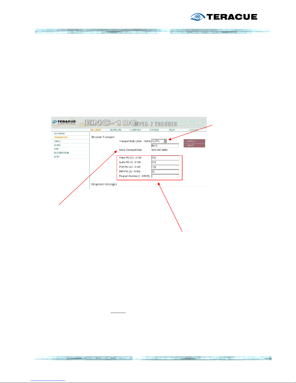
2.4.2 Menu: E
NCODER/TRANSPORT
In the E
NCODER/TRANSPORT
menu, you are able to specify the encoders T
RANSPORT RATE
and set
the Video, Audio and PCR PIDs.
PID stands for Packet Identification.
The PIDs help to identify and locate the elementary signals in a stream containing lots of
different information and signals (audio, video and data). This is necessary due to the
multiplexed nature of transport streams.
A
CTUAL TRANSPORT RATE
:
The status information
displayed here shows the
actual stream transport rate,
i.e. the network bandwidth of
the stream.
Here you can adjust
whether the ENC is
to adapt the
transport rate
automatically with a
change of the video
bitrate.
If you select AUTO,
the ENC-100 adapts
the Transport Rate
automatically.
.!. We recommend
.!. We recommend .!. We recommend
.!. We recommend
using t
using tusing t
using the AUTO
he AUTO he AUTO
he AUTO
setting.
setting.setting.
setting.
.!. If the Tran
.!. If the Tran.!. If the Tran
.!. If the Transport Rate
sport Ratesport Rate
sport Rate---- and the Video
and the Video and the Video
and the Video
Bitrate
Bitrate Bitrate
Bitrate----Settings are in conflict to one
Settings are in conflict to one Settings are in conflict to one
Settings are in conflict to one
another, you will be notified and the
another, you will be notified and the another, you will be notified and the
another, you will be notified and the
Transport or Video Bitrate will be
Transport or Video Bitrate will be Transport or Video Bitrate will be
Transport or Video Bitrate will be
automatically set to solve this conflict.
automatically set to solve this conflict. automatically set to solve this conflict.
automatically set to solve this conflict.
(e.g. the Transport Bitrate
(e.g. the Transport Bitrate (e.g. the Transport Bitrate
(e.g. the Transport Bitrate cannot
cannotcannot
cannot
be lower than the Video Bitrate.)
be lower than the Video Bitrate.) be lower than the Video Bitrate.)
be lower than the Video Bitrate.)
.!. If you are uncertain about using and
.!. If you are uncertain about using and .!. If you are uncertain about using and
.!. If you are uncertain about using and
setting the PIDs, we recommend
setting the PIDs, we recommend setting the PIDs, we recommend
setting the PIDs, we recommend
leaving them at the defined default
leaving them at the defined default leaving them at the defined default
leaving them at the defined default
values.
values. values.
values.
VVVVideo
ideo ideo
ideo PID
PIDPID
PID 256
256256
256
AAAAudio
udioudio
udio PID
PID PID
PID 259
259259
259
PCR PID
PCR PIDPCR PID
PCR PID 128
128128
128
PMT PID
PMT PIDPMT PID
PMT PID 32
3232
32
Program Number
Program NumberProgram Number
Program Number 1111
Simply type in a T
RANSPORT RATE, VIDEO
PID,
A
UDIO
PID, PCR PID (Program Clock Reference),
PMT PID (Program Map Table) or Program
Number and hit the A
PPLY
or S
AVE BUTTON
.
Page 25
25
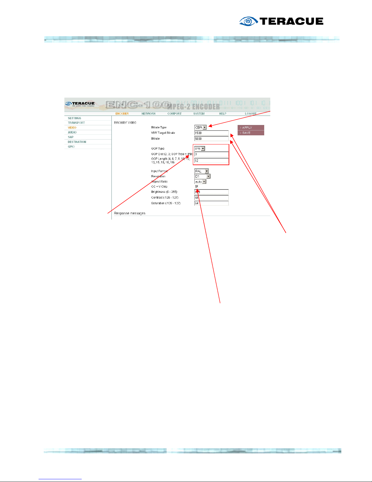
2.4.3 Menu: E
NCODER/VIDEO
This menu lets you define the V
IDEO ENCODING PROPERTIES
.
C
HOOSE BET
-
WEEN ENCODING
WITH A CONSTANT
BITR
ATE
(CBR),
OR A VARIABLE
BITR
ATE
(VBR).
.!. We
recommend CBR.
Set your desired Video Bitrate.
When using a VBR, these 2 setting
may differ.
B
UT
when you encode using a CBR,
please make sure that both
settings correspond.
GGGG
OP
OP OP
OP
====
MPEG
MPEGMPEG
MPEG
TTTT
ERM FOR A
ERM FOR A ERM FOR A
ERM FOR A
GGGG
ROUP
ROUP ROUP
ROUP
OOOO
F
F F
F
PPPP
ICTURES
ICTURESICTURES
ICTURES
,,,,
I
I I
I
....
EEEE
....
AN
AN AN
AN
EEEE
NCODING
NCODING NCODING
NCODING
SSSS
EQUENCE
EQUENCEEQUENCE
EQUENCE
....
GOP-T
YPE
:
Select between encoding a stream
consisting of either
I-, IP- or IPB-Frames.
GOP-D
ISTANCE
:
Specifies the GOP-
Type together with
GOP-Length:
0 = I-Frames only
1 = IP-Frames
2 = IBP-Frames
3 = IBBP-Frames
(see next page for an overview)
GOP-L
ENGTH
:
Specifies the length of a GOP, i.e.
the number of frames (pictures) that
a GOP consists of. Counting from IFrame to the last frame in the GOP.
CC + V-Chip (Only for NTSC)
If you check this box the encoder will
pass the CC (Close Caption) and/or
V-Chip (Violence Chip) signal in line
21 of the analog NTSC input signal.
Page 26
26
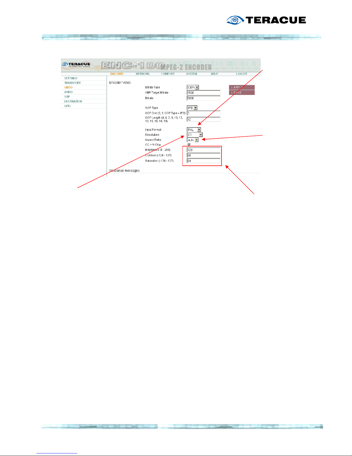
Choose
between NTSC
and PAL
composite
video input
format.
Choose the
Aspect Ratio
(See 2.4.3.1)
.!. We
recommend
“auto”
Video encoding resolution
Four different resolutions can be selected.
You can choose between:
Full D1 720h x 480/576v
Half-D1: 384h x 480/576v
2/3 D1 544h x 480/576v
CIF: 384h x 240/288v
With CIF resolution the bandwidth of the encoded
stream can now be as low as 800kbit/s.
For Half D1 the min. required bandwidth is 1Mbit/s.
2/3 D1 streams can be as narrow as 1,5Mbit/s.
Full D1 streams can have a min. bandwidth of 2Mbit/s.
B
RIGHTNESS, CONTRAST, SATURATION
:
The Brightness, Contrast and
Saturation of the encoded video
stream can be controlled by these
settings.
The standard settings are:
Brightness: 128
Contrast: 68
Saturation: 64
Page 27

27
2.4.3.1 Aspect Ratio
The ENC-100 supports encoding and streaming of signals with different aspect ratios
(4:3/16:9) since firmware version 3.01.
If an analogue input signal includes the WSS (Wide Screen Signal) the ENC-100 can detect
whether the input signal is in 16:9 or in 4:3, when menu “Aspect Ratio” is switched to “auto”.
The Wide Screen Signal is included in the first half of line 23 in the PAL standard video signal.
The ENC-100 switches to 4:3 if no WSS is included.
If your video source doesn’t include the WSS in its analogue output signal, although you have
a 16:9 signal, you can manually switch the ENC-100 to “16:9” or “4:3” in the “Aspect Ratio””””
drop down menu of the “video” settings.
To view a 16:9 signal correctly on your screen, your decoder has to detect the 16:9 Flag in
the header of the MPEG-2 Transport Stream coming from the ENC-100.
Examples for decoders that work with this signal are the Standalone XPlayer, iCue XPlayer
and the Set Top Box AmiNet110 (former STB-100).
If you use the XPlayer just choose a stream and the XPlayer will automatically switch to 4:3 or
16:9.
For information about the settings of the STB-100 please take a look at the STB-100 user
guide (1.0.4 or later).
Page 28
28
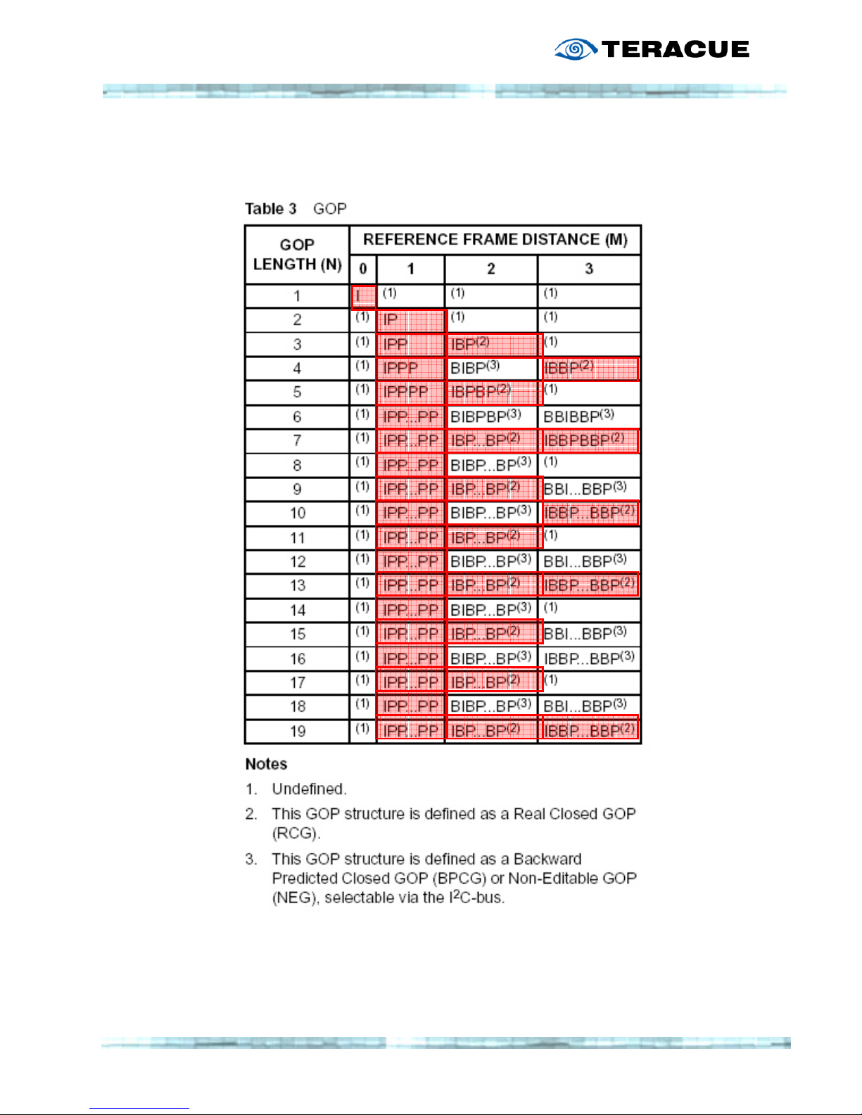
2.4.3.2 GOP Type Overview (I, IP, IBP, IBBP)
.!.
.!..!.
.!. We recommend using
We recommend using We recommend using
We recommend using only
only only
only Real Closed GOPs
Real Closed GOPsReal Closed GOPs
Real Closed GOPs!!!! These
These These
These are marked above by the
are marked above by the are marked above by the
are marked above by the red
red red
red
highlights.
highlights.highlights.
highlights.
Page 29
29
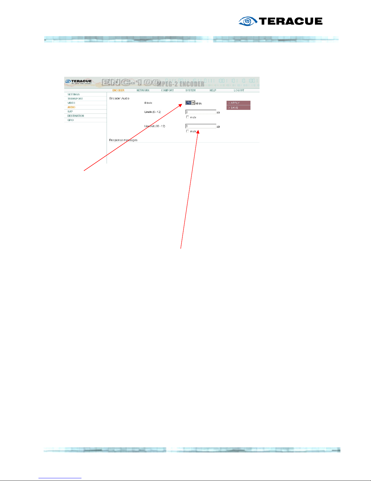
2.4.4 Menu: E
NCODER/AUDIO
Audio encoding bitrate
Select between 384kbit/s and 256kbit/s.
Analog audio will be encoded in
MPEG-1 Layer II, 48kHz, 16bit.
Mute or set the levels with dB gain for the LineIn (Audio In) from 0 – 12 dB if the input signal
is too weak. The LineOut (Audio Out, Talkback) can be adjusted the same way.
.!. Audio will not
.!. Audio will not .!. Audio will not
.!. Audio will not
be encoded if you
be encoded if you be encoded if you
be encoded if you
are encoding a
are encoding a are encoding a
are encoding a
Video Elementary
Video Elementary Video Elementary
Video Elementary
Stream (VES). A
Stream (VES). A Stream (VES). A
Stream (VES). A
VES consists only
VES consists only VES consists only
VES consists only
of a Video Stream.
of a Video Stream. of a Video Stream.
of a Video Stream.
The same applies
The same applies The same applies
The same applies
for Transport
for Transport for Transport
for Transport
Streams with audio
Streams with audio Streams with audio
Streams with audio
only.
only. only.
only.
Page 30
30
2.4.5 Menu: E
NCODER
/SAPS
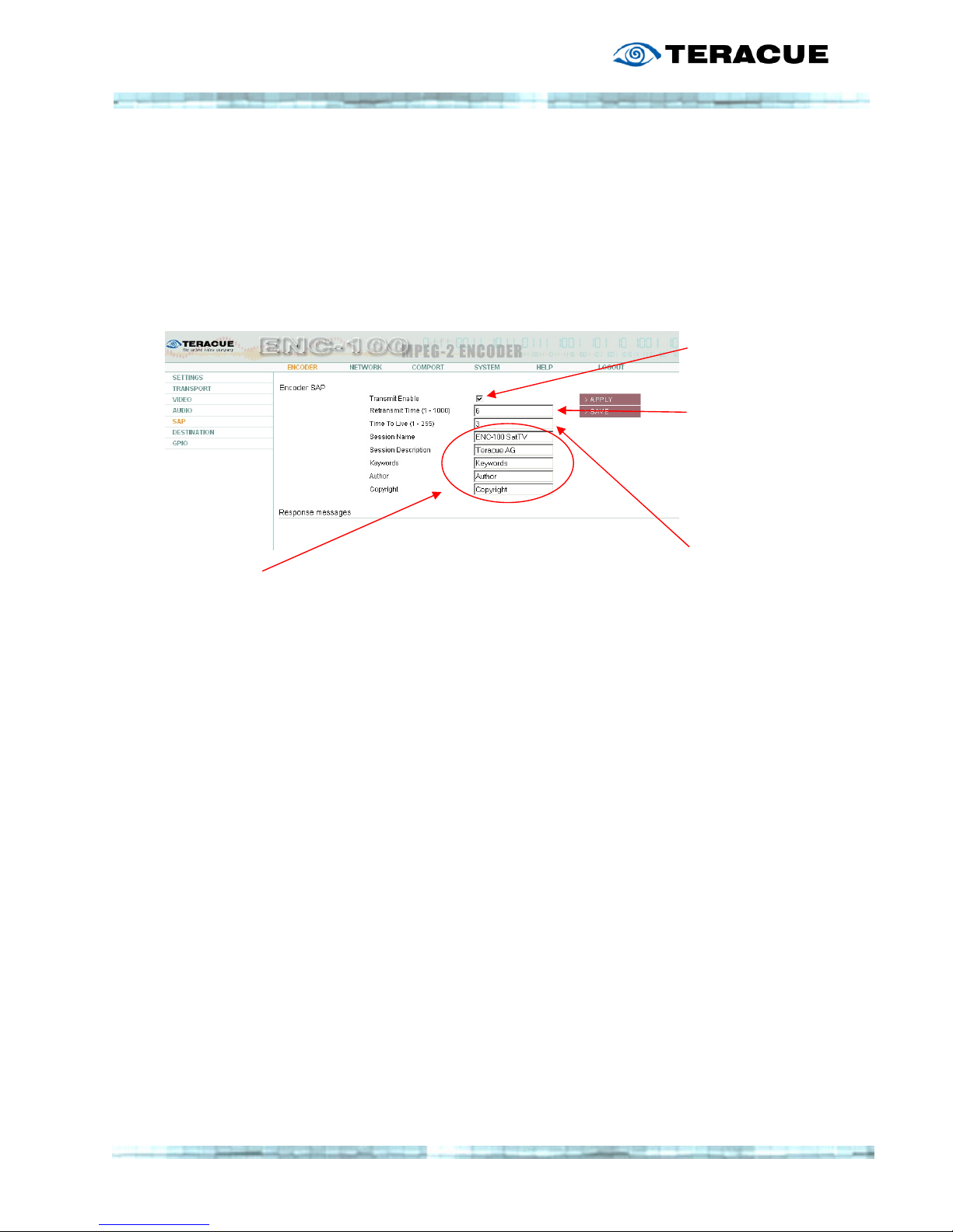
SAPs are Session Announcement Protocols.
A SAP is used to label a stream to guarantee an effective workflow. Streams with SAPs can
easily be located, selected and viewed – due to their description. Please see the screen below
to get an overview of all the properties that can be defined.
T
RANSMIT ENABLE
:
Turn SAP ON/OFF.
R
ETRANSMIT TIME
:
Time in Seconds,
defining how often
a SAP will be sent
into the network.
T
IME TO LIVE
:
Number of
Routers, Switches
a SAP is allowed
to travel/pass.
A
DJUSTABLE
SAP T
EXT PROPERTIES
Page 31
31
2.4.6 Menu: E
NCODER/DESTINATION
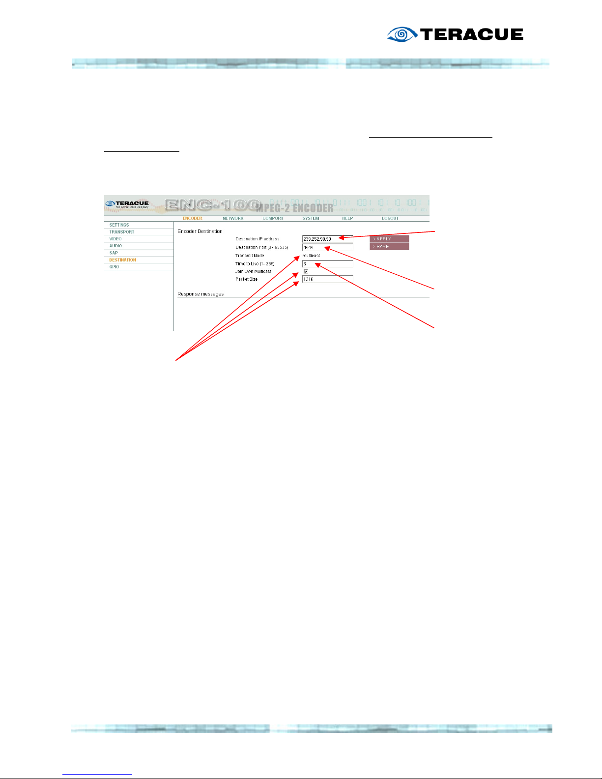
ENC-100 is capable of sending out the encoded stream as either a unicast stream or a
multicast stream.
According to the entered destination IP-address, the encoder will automatically recognize if
it's supposed to send out a unicast or multicast stream.
Enter the
destination IPaddress
and
Destination Port
here
T
IME TO LIVE
:
Number of
routers, switches
that the stream is
allowed to
travel/pass.
TTTT
RANSMIT
RANSMIT RANSMIT
RANSMIT
MMMM
ODE
ODEODE
ODE
::::
Automatically set to Unicast or Multicast, depending on the
entered destination IP-address.
JJJJ
OIN
OIN OIN
OIN
OOOO
WN
WN WN
WN
MMMM
ULTICAST
ULTICASTULTICAST
ULTICAST
::::
This option sends IGMP-2 "join-requests" to routers and switches
in order to keep the multicast port open.
Check this box to enable the encoder to receive his own stream.
Many network switches and routers (e.g. Cisco) support IGMP-2
which close the port, when noone is receiving the stream, i.e.
noone is viewing a stream.
By checking this box the encoder will act as if it is receiving a
stream and keep the port open.
.!. We strongly recommend to use this option.
.!. We strongly recommend to use this option..!. We strongly recommend to use this option.
.!. We strongly recommend to use this option.
PPPP
ACKET
ACKET ACKET
ACKET
SSSS
IZE
IZEIZE
IZE
::::
Enter the Packet Size here.
.!. We recommend
.!. We recommend.!. We recommend
.!. We recommend to use a Packet Size of 1316 Bytes.
to use a Packet Size of 1316 Bytes. to use a Packet Size of 1316 Bytes.
to use a Packet Size of 1316 Bytes.
Page 32
32
2.4.7 Menu: E
NCODER
/GPIO
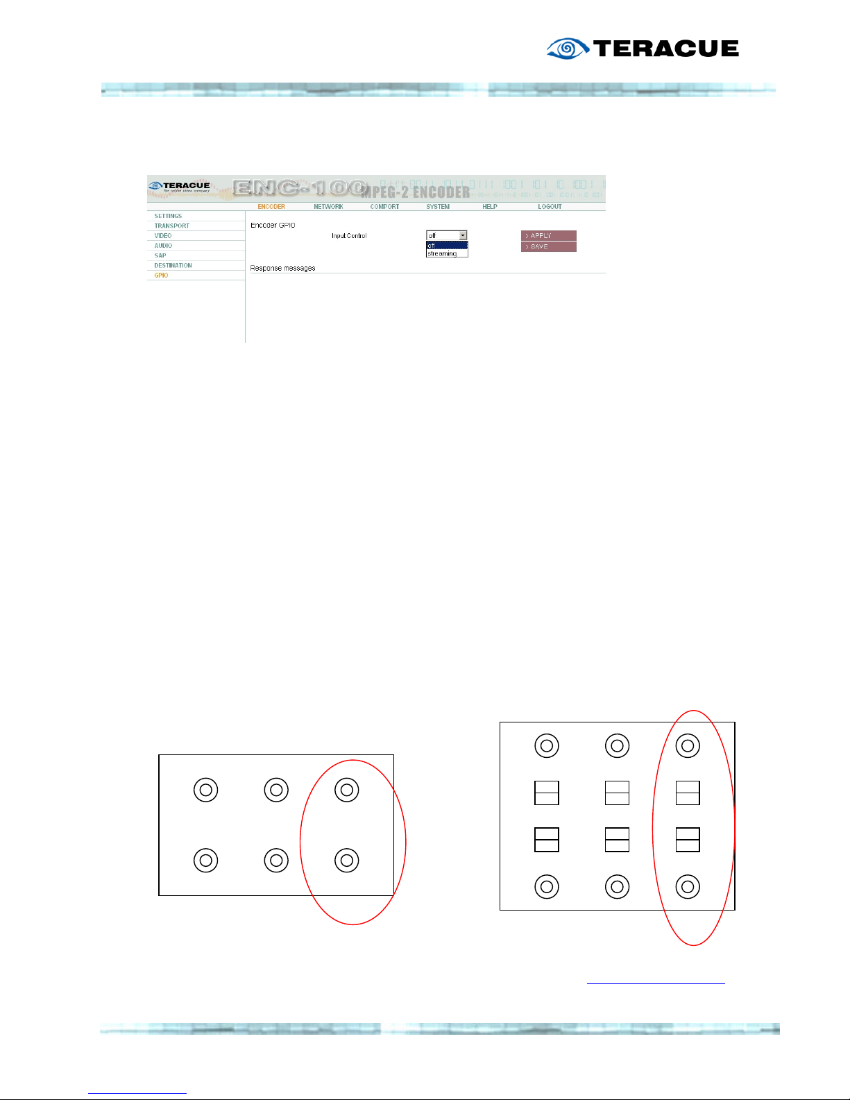
The General Purpose Interface currently only supports a GPI IN function for controlling the
setting "Transmit enable" on/off. This allows users to connect a special device, e.g. foot
pedal or on/off switch to the GPIO Port and use the foot pedal, switch to turn the ENC-100
streaming function on/off.
The connectors are described as below. For operation of the GPI IN triggering as described
the two (right) IN pins need to be operated closed circuit. When contact between both IN pins
is created the status of the ENC-100 will change (streaming on/off).
When ENC-100 is set on web GUI to GPI IN "streaming", then ENC-100 will stream when the
IN pin circuit is closed. When IN pin circuit is open, the ENC-100 will not generate a stream.
(Out and middle pins are not yet supported.)
As this is only necessary for special operating modes, please contact
for further information.
GPIO CONNECTOR
Connectors, Pins on ENC-100 blade
OUT IN
GPIO A
DAPTER
(Black GPIO Adapter)
OUT IN
Page 33

33
GPO will be supported with the next firmware version releases.
Please see chapter "Firmware Update" for more information.
.!.
.!..!.
.!. If no GPI IN switching dev
If no GPI IN switching devIf no GPI IN switching dev
If no GPI IN switching device is connected to the ENC
ice is connected to the ENCice is connected to the ENC
ice is connected to the ENC----100 the setting on this menu
100 the setting on this menu 100 the setting on this menu
100 the setting on this menu
must be set to off. Otherwise the ENC
must be set to off. Otherwise the ENCmust be set to off. Otherwise the ENC
must be set to off. Otherwise the ENC----100 will not start encoding and streaming.
100 will not start encoding and streaming.100 will not start encoding and streaming.
100 will not start encoding and streaming.
2.4.8 Menu: N
ETWORK/SETTINGS
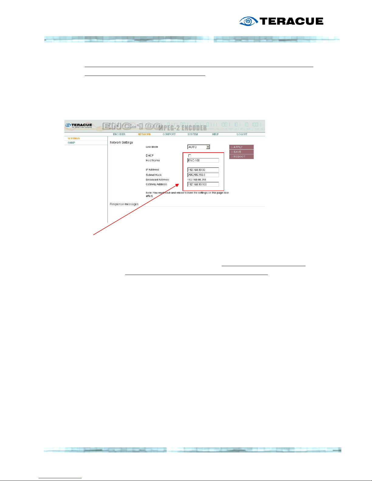
Here you are able to set the encoder's own IP-address, Subnet Mask, Gateway Address and
define the encoder's Host Name.
Link mode
This option enables users to configure the ENC’s network port charateristics.
You can choose between these options:
AUTO
100MbTX-FD (100 Mbit/s, Twisted Pair, Full Duplex)
100MbTX-HD (100 Mbit/s, Twisted Pair, Half Duplex)
10Mb-FD (10 Mbit/s, Full Duplex)
10Mb-HD (10 Mbit/s, Half Duplex)
This option has been added especially to address specialzied network and/or administration
reqirements.
.!. In most cases it is sufficient (and recommended) to leave this setting on AUTO, so the
ENC-100 and the connected switch can deal out the preferred connection on their own.
(AUTO has been the default link mode setting up to firmware version V2.01)
Page 34
34
.!.
.!..!.
.!. When the IP
When the IPWhen the IP
When the IP----address has been changed, the encoder needs to be reset (reboot), in
address has been changed, the encoder needs to be reset (reboot), in address has been changed, the encoder needs to be reset (reboot), in
address has been changed, the encoder needs to be reset (reboot), in
order for the new IP
order for the new IPorder for the new IP
order for the new IP----address to take effect.
address to take effect.address to take effect.
address to take effect.
When changing the IP-address please type in the new IP-address, Subnet Mask,
Gateway-Address and Host Name. Then hit the S
AVE BUTTON
and then the R
EBOOT
BUTTON
.
Network Settings
Network SettingsNetwork Settings
Network Settings
DHCP: Select this option to enable DHCP. Only use this option if you are
familiar with DCHP and your network supports this.
Hostname: Enter a hostname for ENC-100 blade.
IP Address: The IP Address is an identifier for your ENC in the TCP/IP network.
Networks use the TCP/IP protocol route messages based on the IP
address of the destination. The Format of an IP address is a 32-bit
numeric address written as four numbers separated by periods. Each
number can range from 0 to 255.
e.g. 172.16.20.100
Subnet Mask: A Subnet Mask is a 32-bitmask used to divide an IP address into
subnet and specify the networks available hosts.
e.g. 255.255.0.0 is the netmask for a class C IP address like
172.16.20.100
Gateway: The gateway is commonly the address of the network device such as a
network router.
Page 35

35
2.4.9 Menu: N
ETWORK
/SNMP (S
IMPLE NETWORK MANAGEMENT PROTOCOL
)
The Simple Network Management Protocol enables you to monitor and/or configure network
attached devices like the ENC-100, made possible by the installed SNMP agents.
Every ENC-100 since Firmware Version 3.01 is delivered with an SNMP agent. All you need
are the MIB (Management Information Base) files. With these MIB files you can use all
advantages of SNMP associated with the ENC-100.
You can find the appropriate MIB files, TERACUE-ENC100-MIB.txt and
TERACUE-SNMP-MIB.txt on the Teracue website IPTV Support Area. Or contact
With these MIBs and an SNMP manager you have the possibility to monitor the ENC-100
status (by SNMP traps) or remotely configure every function of the ENC-100 similar to the
normal access via web browser. There are various SNMP management tools available to issue
SNMP based commands to the appliance (Software not supplied by Teracue).
.!. Set your SNMP manager to SNMPv2.
.!. Set your SNMP manager to SNMPv2..!. Set your SNMP manager to SNMPv2.
.!. Set your SNMP manager to SNMPv2.
Teracue uses the MIB Browser by iReasoning to monitor/set up the ENC-100. iReasoning
offers a free version of the MIB Browser under www.ireasoning.com, which is useful to read
the actual status or setting up the ENC-100. See below for further information.
SNMP uses the following standard ports: Port 161 and port 162
Port 161 is used by the SNMP manager and the agent to send the Requests and their
Responses.
Port 162 is used by the SNMP agent to send TRAPs to the SNMP manager.
Make sure that these ports are not blocked in your network.
The following operations are possible with SNMP
GET Read out the management information
GETNEXT Read out the management information iteratively, which is useful if you want
to read the information down the MIB tree step by step
GETBULK Read out the management information of the complete list/tree
SET Change/set the management information
TRAP Start the Trap receiver in your SNMP manager to get alerts of the managed
system e.g. the encoder was started/stopped
Page 36
36
ENC-100 SNMP Settings
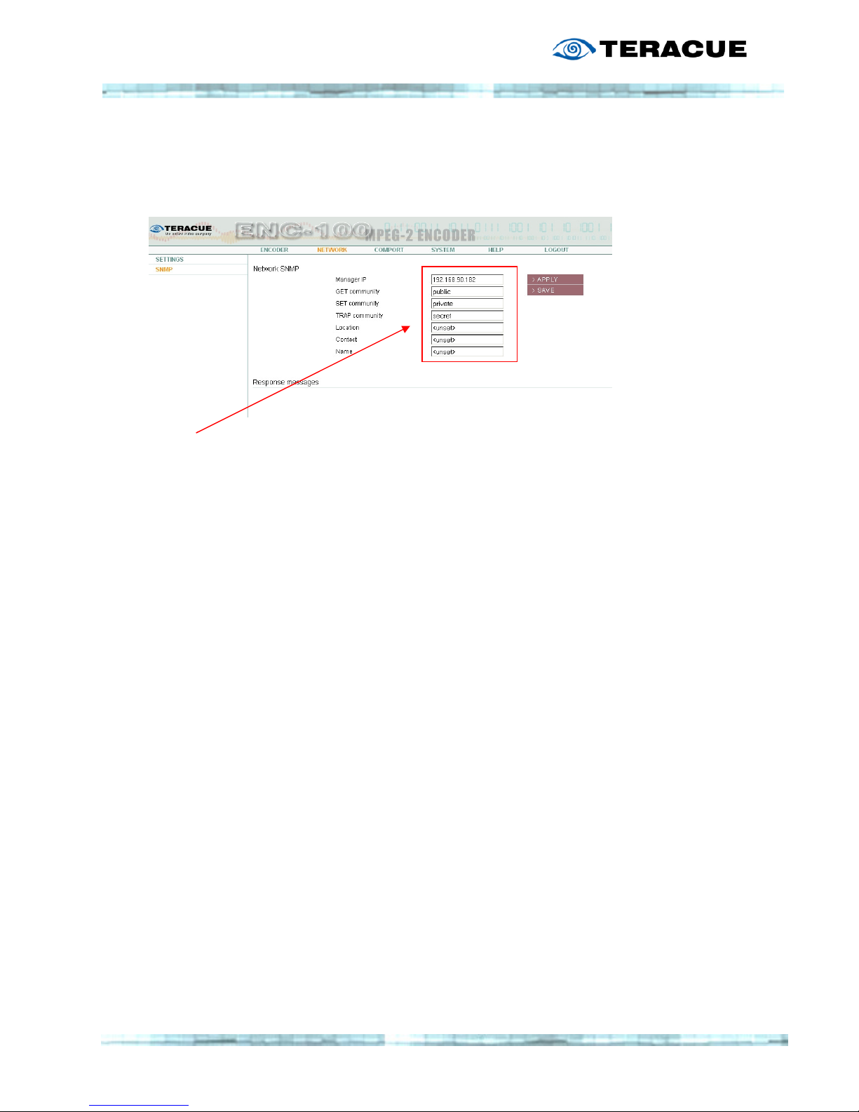
To use the ENC-100 SNMP features, you have to set up the encoder, to establish access with
your SNMP manager.
SNMP Settings
SNMP SettingsSNMP Settings
SNMP Settings
Manager IP: To receive TRAPs, enter the IP Address of the Client PC were the SNMP
manager (TRAP Receiver) is installed
GET community: Type in the password for the GET community which you have to enter
in your SNMP manager in the Read Community field
(We recommend to leave the default value)
SET community: Type in the password for the SET community which you have to enter in
your SNMP manager in the Write Community field
(We recommend to leave the default value)
TRAP community: The TRAP community describes a community string similar to the GET
and SET community string but for Traps. The SNMP TRAP server can
find out whether the received TRAP message was sent by an authorized
client or not.
The three following fields describe the common SNMP-parameters (sysLocation, sysContact
and sysName) supported by every SNMP device. These details help you to find and identify
SNMP devices like the ENC-100 in a network.
Location: The location of the SNMP-node in the network
Contact: The name of the contact person/administrator who is responsible for
this device
Name: The FQDN (Fully Qualified Domain Name) or the hostname of the
device
Page 37
37
The SNMP elements use traps as SNMP base messages to report changes in status or alarm
conditions to remote SNMP management entities. Normally traps are used to alarm network
administrators of possible equipment problems or other important events. There are two
types of information send by the trap device: Events and Alarms.
Event traps
will be sent if a monitored event occurs. These traps have only one state.
Alarm traps
are events that have two states: Active and Clear. An “Active” trap will be sent if
an alarm condition will be detected. The alarm will be kept active until the condition cleared
and a “Clear” trap was send
The ENC-100 has the following trap alerts:
enc100Start:
enc100Start: enc100Start:
enc100Start: This trap is sent when the agent starts
This trap is sent when the agent startsThis trap is sent when the agent starts
This trap is sent when the agent starts
enc100Shutdown:
enc100Shutdown: enc100Shutdown:
enc100Shutdown: This trap is sent when the agent terminates
This trap is sent when the agent terminatesThis trap is sent when the agent terminates
This trap is sent when the agent terminates
enc100GpioInputNotif:
enc100GpioInputNotif: enc100GpioInputNotif:
enc100GpioInputNotif: Sent when state of G
Sent when state of GSent when state of G
Sent when state of GPIO input pin changes
PIO input pin changesPIO input pin changes
PIO input pin changes
To explain the use of SNMP, the following sites will give you a short overview of the
possibilities you have via SNMP. Explained by the SNMP manager “MIB Browser” by
iReasoning.
Setting up the MIB Browser
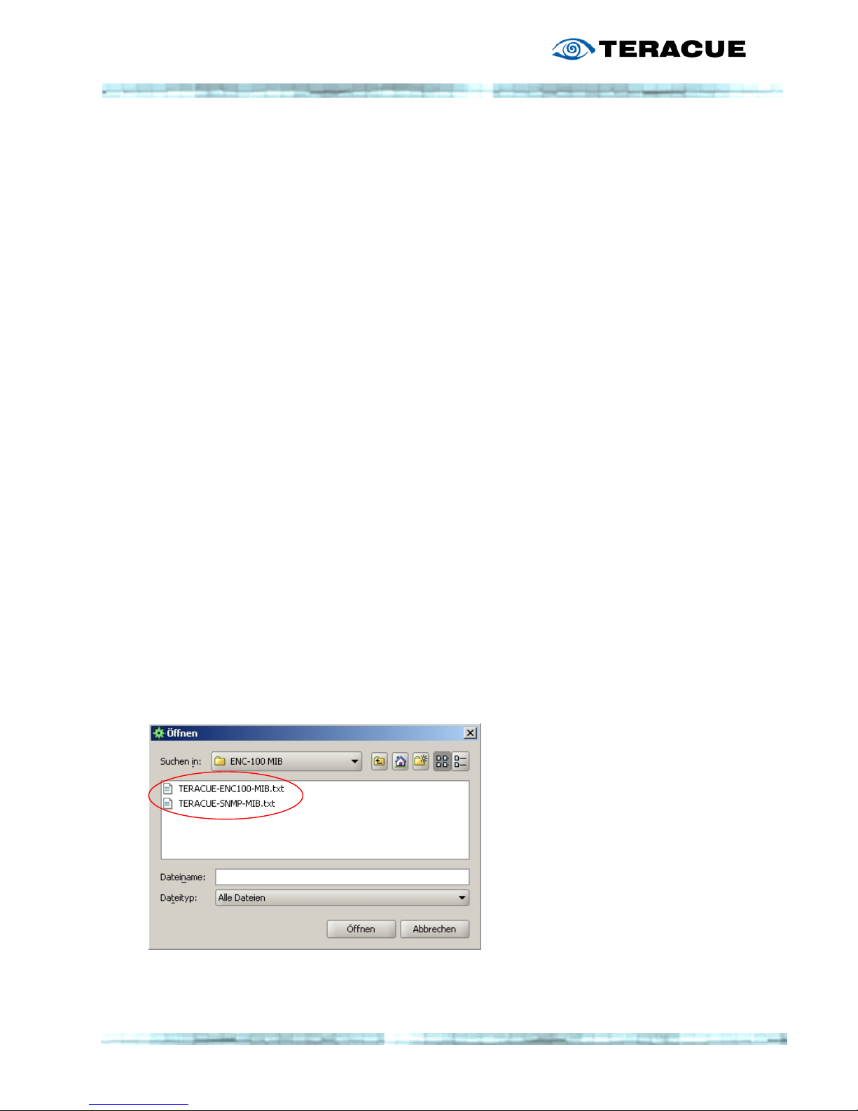
Load the MIB files
Click on File > Load MIB and choose the folder with the MIB files:
You have to load
You have to loadYou have to load
You have to load both files; TERACUE
both files; TERACUE both files; TERACUE
both files; TERACUE----ENC100
ENC100ENC100
ENC100----MIB.txt and TERACUE
MIB.txt and TERACUEMIB.txt and TERACUE
MIB.txt and TERACUE----SNMP
SNMPSNMP
SNMP----MIB.txt
MIB.txtMIB.txt
MIB.txt
Page 38
38
Setting up the agent
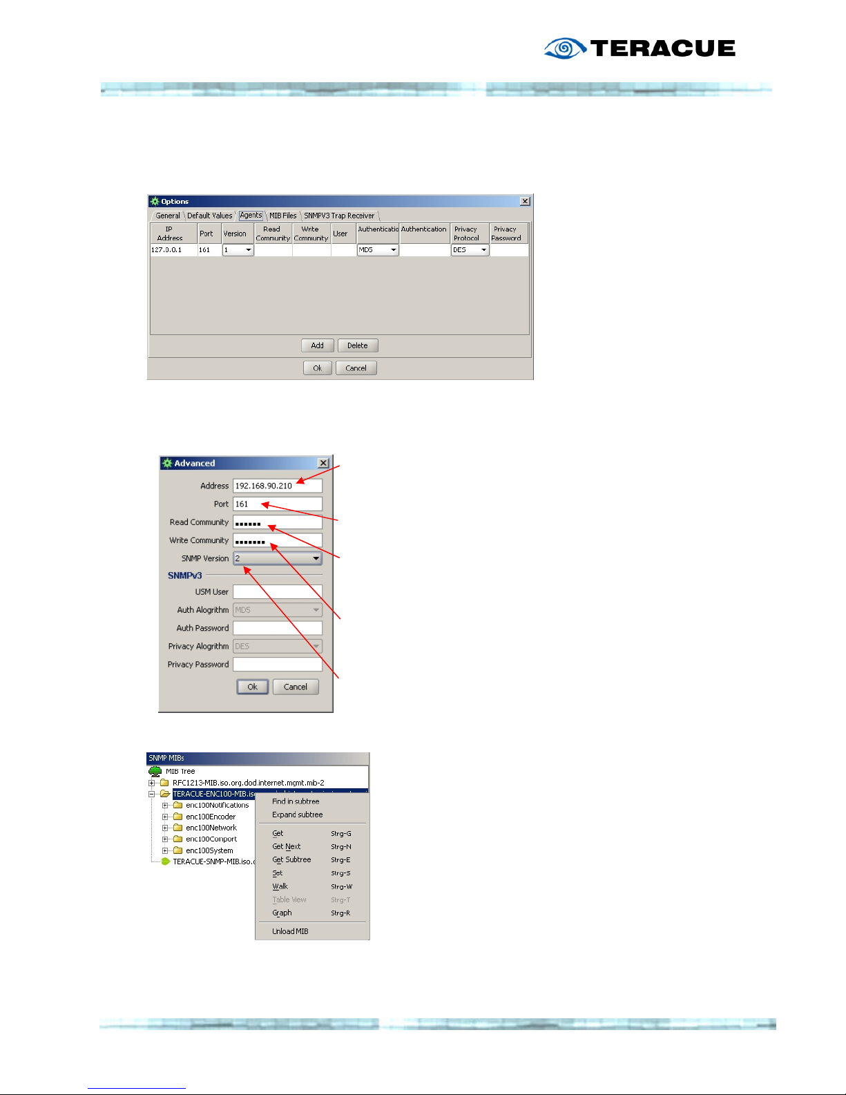
Click on Tools > Options and choose “Agents”
Click on “Add” and the following window will open to add an SNMP device
Type in the IP-address of the SNMP device. In this case the IPaddress of the ENC-100
Leave the Port to 161, or change if it is set to another one.
Type in the “Read Community” password. The default
password of the ENC-100 is “public”
Type in the “Write Community” password. The default
password of the ENC-100 is “private”
Set the SNMP Version to 2
Choose the loaded Teracue ENC-100 MIB and right click
on it. Click on “Expand subtree” to see all options of the
ENC-100.
Page 39
39
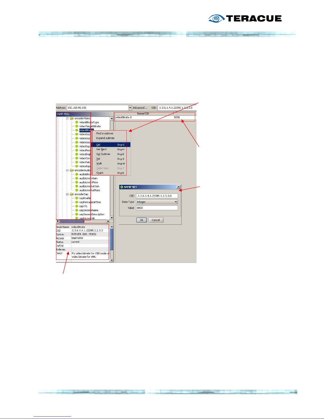
The opened subtree shows you all the adjustable options, you also have with the web
interface.
The next example shows you how to use the MIB Browser, explained by the ENC-100 menu
item “videoBitrate”.
Right click on the option
“videoBitrate”. You can now
choose “Get” “Get Next” “Get
Subtree” “Set” “Walk” or “Graph”
(see next site for more
information).
If you choose “Get” for the
videoBitrate, the MIB Browser will
show the actual setting.
In this case 5000 which stands
for 5000kBit/s
If you choose “Set”, a new
window pops up to enter the new
value of the selected item.
Choose the right “DataType” and
enter the new “Value” e.g. 8000
In this window you see the options of the selected menu item.
E.g. the videoBitrate
Syntax: Integer (800.15000) You can choose a video bitrate from 800kBit/s to
5000kBit/s
Access: read-write You are able to read and write the actual settings of your
device
Page 40

40
Node Name
This shows you the name of the selected item
OID
The Object Identifier (OID) is the explicit SNMP number of the selected item/function
Syntax
Integer: Read-only/read-write normal numbers in the possible range of
Integer32: Read-only normal numbers in the possible range of
Octet String: Read-only/read-write numbers and characters (e.g. Teracue)
IPAddress: Read-only/read-write numbers in the IP address string (e.g. 172.16.20.100)
Access
The attribute read-only or read-write shows you if you can change the selected item or if you
just able to read out the actual setting or state
Descr
This field gives you a short description of the selected item
The common operations of the MIB Browser are:
Get Read out the management information
Get Next Read out the management information iteratively, which is useful if you want
to read the information down the MIB tree step by step
Get Subtree Read out the management information of the selected subtree
Walk (Getbulk) Read out the management information of the complete list/tree
Set Change/set the management information
Page 41
41
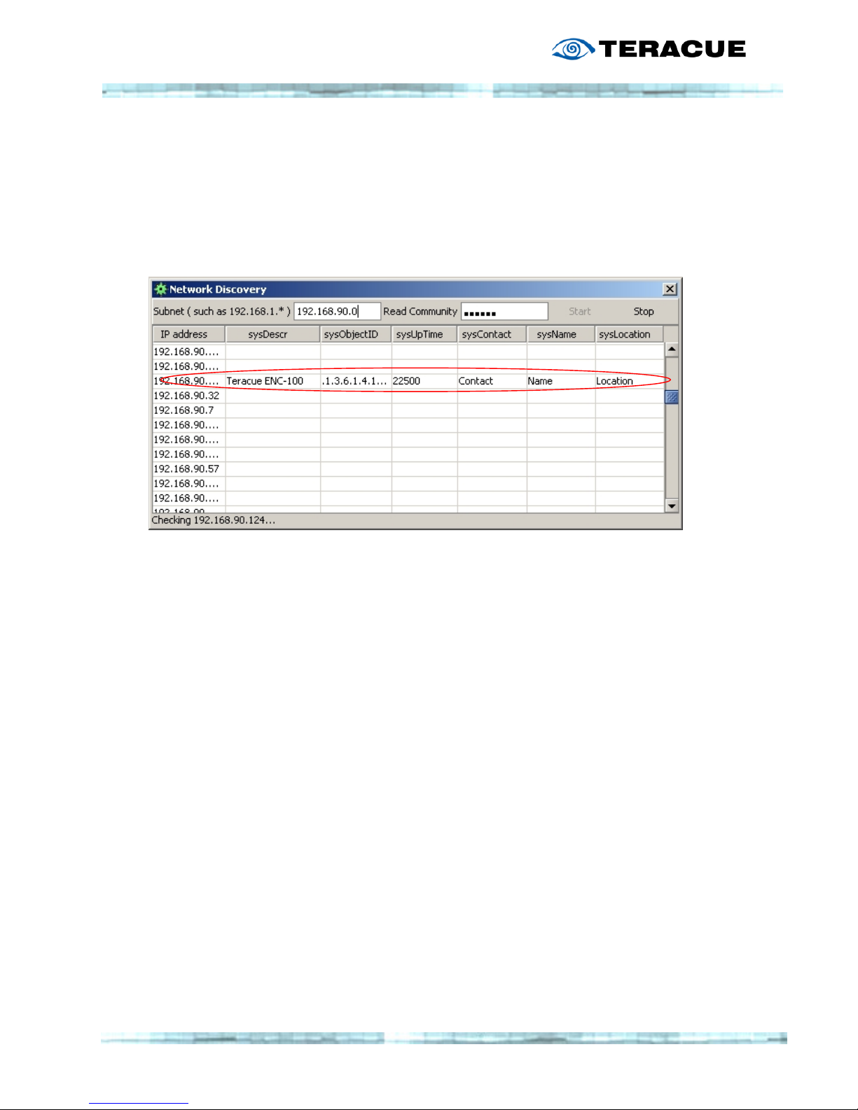
Network Discovery
Click on Tools > Network Discovery
Type in the IP address of your subnet with a zero as last number of the IP address (e.g.
192.168.90.0) and press “Start”. The MIB Browser starts to scan the LAN for encoders or
other SNMP devices that can be controlled by a SNMP manager.
The following list shows an example of the available devices. In this case the ENC-100
sysDescr: The Name of the network device: e.g. Teracue ENC-100
sysObjectID: This shows the explicit MIB ID of the device.
sysUpTime: This shows the uptime to the device in seconds multiplied by hundred
sysUpTime = 27780500
-> 27780500 / 100 = 277805 seconds = 3 days 5 hours 10 minutes 5 seconds
sysContact: The name of the contact person/administrator who is responsible for this device
sysName: The FQDN (Fully Qualified Domain Name) or the hostname of the device
sysLocation: The location of the SNMP-device in the network
Page 42

42
2.4.10 Menu: C
OMPORT/SETTINGS
This menu defines the parameters for the ENC's integrated comport/serial port.
Mode: C
ONSOLE
– enables access and control of the ENC-100 configuration via
the com-cable (ENC-100-COMCAB). Use this cable to set the ENC
configuration if you do not want to use web access.
P
ASSTHROUGH
– enables setting the comport to a com-server/serial
server mode. RS-232 and RS-485 devices can be connected and
controlled via the comport. This is useful, for example when cameras
or other non-IP, non-network devices need to be remotely controlled.
RS-232/485 commands can be tunneled and sent via TCP/IP to the
ENC-100 comport, where they then will be returned into native RS232/485 commands.
When a connection is opened to the IP Address of the encoder at port
7777, the serial server function in the ENC-100 is activated and any
data (string) is passed straight to the connected RS-232/485 device.
Once the connection is established, this also works the other way for
information coming back from the RS-232/485 device.
Bitrate, Databits, Parity, Stopbits, Flowcontrol:
Allows to set the comport parameters in order to match the exact
protocol for connected RS-232/485 equipment.
Page 43
43
2.4.10.1 Setting RS-232 or RS-485
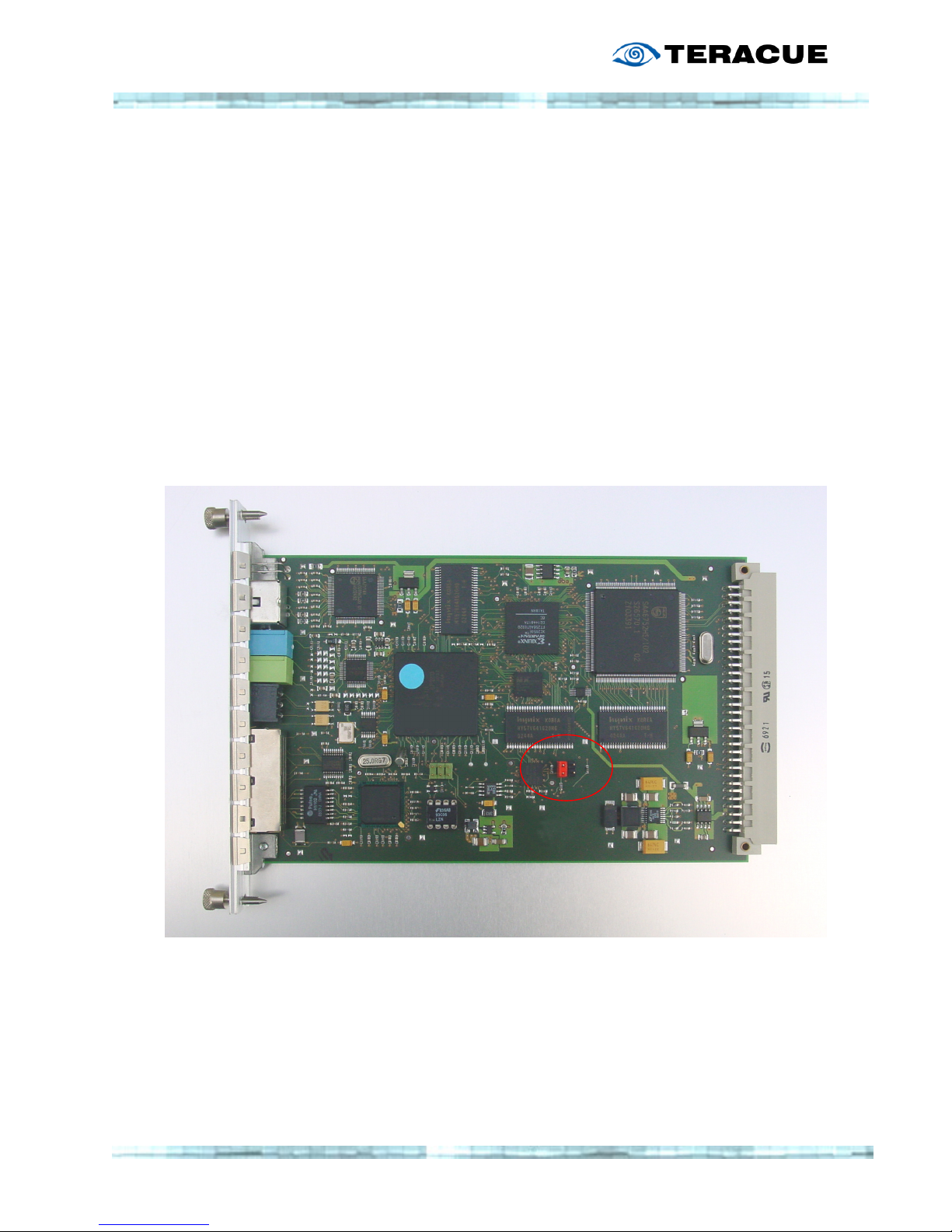
To change the support of RS-232 or RS-485 devices, please power down the encoder chassis
and remove the ENC-100 blade gently from the chassis. Hold the encoder blade as shown
below, with the video input pointing to the left.
RS-232 setting: For supporting RS-232 devices on the comport the red jumper must be
situated on the pair of left pins, as shown below.
RS-485 setting: For supporting RS-485 devices please remove the red jumper from the
ENC-100 blade. Please store it in a save place, so you can use it again
in the future.
Page 44

44
2.4.10.2 Example code for a Panasonic X?X camera
The application was used to send commands to a camera, waiting for a status and returning
a command.
#include <stdio.h>
#include <stdlib.h>
#include <string.h>
#include <unistd.h>
#include <getopt.h>
#include <sys/types.h>
#include <sys/stat.h>
#include <fcntl.h>
#include <sys/socket.h>
#include <netinet/in.h>
#include <arpa/inet.h>
//-----------------------------------------------------------------------------
int main(int argc, char **argv)
{
extern char *optarg;
extern int optind;
const char *hostname = "192.168.3.44";
bool errflg = false;
while(1) {
int c = getopt(argc,argv,"h:");
if(c == -1)
break;
switch (c) {
case 'h':
hostname = optarg;
break;
default:
errflg = true;
}
}
if(errflg || optind!=argc) {
fprintf
( stderr,
"usage:\n"
" %s [-h numeric-hostname]\n",
argv[0]
);
exit(1);
}
//--------------------------------------------------
int fd = socket(AF_INET,SOCK_STREAM,IPPROTO_IP);
if(-1 == fd) {
perror("socket");
exit(1);
}
const int on = 1;
Page 45

45
if (setsockopt(fd, SOL_SOCKET, SO_REUSEADDR, (char *)&on, sizeof(on)))
fprintf(stderr,"setsockopt SO_REUSEADDR on fails:\n");
struct sockaddr_in addr;
bzero(&addr,sizeof(addr));
addr.sin_family = AF_INET;
addr.sin_port = htons(7777);
if(!inet_aton(hostname,&addr.sin_addr)) {
fprintf(stderr,"adr fehler \"%s\"\n",hostname);
exit(1);
}
if(connect(fd, (struct sockaddr *) &addr, sizeof(addr))) {
perror("connect");
exit(1);
}
//--------------------------------------------------
#define STX "\002"
#define ETX "\003"
#define ACK "\006"
const char cmd/*all reset*/[] = STX "GC7:0021760" ETX;
// const char cmd[] = STX "RON:0" ETX;
// const char cmd/*iris_close*/[] = STX "GC7:0021003" ETX;
// const char cmd/*iris open*/[] = STX "GC7:0021002" ETX;
write(fd,cmd,sizeof(cmd)-1);
// FIXME..
// then wait for ACK, then read answer, then send ACK
unsigned char buf[256];
int n;
while(0 < (n = read(fd,buf,sizeof(buf)))) {
for (int i = 0; i < n; ++i)
fprintf (stdout, "buf[%d]: %02x '%c'\n", i, buf[i], buf[i]);
// printf("%.*s",n,buf);
fflush(stdout);
}
exit(0);
}
Page 46

46
2.4.11 Menu: S
YSTEM/SETTINGS
The menu S
YSTEM/SETTINGS
displays information about the firmware version that is installed on
your ENC-100.
After the firmware version number you will find either: CVBS for Composite images (FBAS),
Y/C for S-Video firmware images or SDI.
The encoder's MAC A
DDRESS
is also listed under this menu. The MAC address should
correspond to the end of the serial number of your encoder.
Furthermore you will find information about System uptime, CPU load, processor core
temperature, the current power supply voltage and the Link Mode.
.!. The
.!. The .!. The
.!. The pppprocessor
rocessor rocessor
rocessor core
core core
core temperature should
temperature should temperature should
temperature should not exceed +
not exceed +not exceed +
not exceed +75
7575
75°C.
°C.°C.
°C.
Page 47

47
2.4.11.1 Menu: S
YSTEM/PASSWORD
.!.
.!..!.
.!.
Unless your encoder is used in very critical scenarios, we recommend to leave the
Unless your encoder is used in very critical scenarios, we recommend to leave theUnless your encoder is used in very critical scenarios, we recommend to leave the
Unless your encoder is used in very critical scenarios, we recommend to leave the
password set to it
password set to itpassword set to it
password set to itssss default value ("admin", "admin").
default value ("admin", "admin"). default value ("admin", "admin").
default value ("admin", "admin").
If you do need to change the password due to security issues, then simply click on the
submenu password and enter the new password twice in the provided boxes. Then hit the
apply button.
Page 48
48
2.4.11.2 Menu: S
YSTEM/UPDATE
(upgrading firmware version)
Teracue's goal is customer satisfaction and constant product improvement.
Please check regularly to see if the most recent firmware version is installed on your
ENC-100. Please visit the IPTV Support Area on: www.teracue.com
To install a new firmware on the encoder, you need the following file:
Firmware Update for ENC
Firmware Update for ENCFirmware Update for ENC
Firmware Update for ENC----100 V
100 V100 V
100 V3.03
3.033.03
3.03
Firmware versions can be downloaded from the Teracue support website listed above.
Download the correct firmware version that you wish to update your encoders with and save
it locally on your computer. The firmware version file e.g. for version 3.03 Y/C, S-Video is
called: "enc
encenc
enc100_v3.03
100_v3.03100_v3.03
100_v3.03_yc
_yc_yc
_yc"
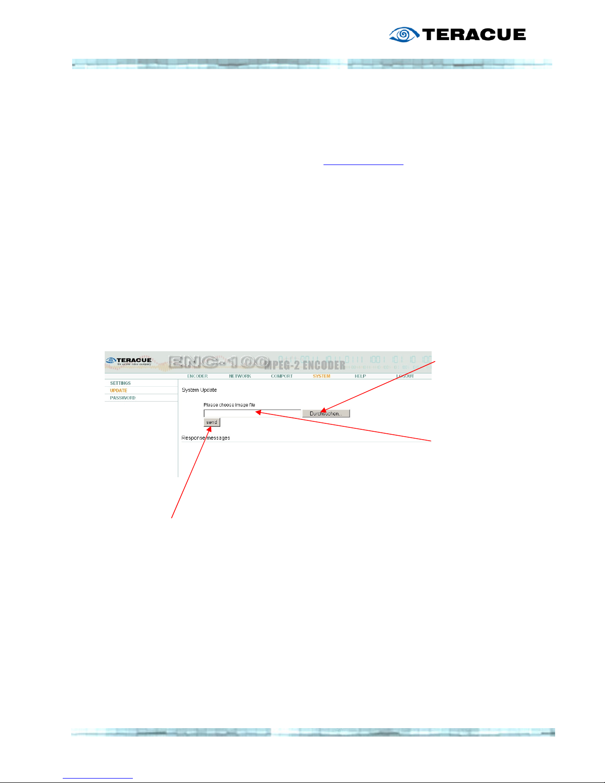
Open the configuration webpage of the ENC-100 and select the submenu
UPDATE
within the
menu S
YSTEM
.
Click on the
BROWSE
button to locate
the file on your
local hard drive.
Hit
OK
and the path
to the file will be
listed in the box in
the middle of the
screen.
To start the firmware update procedure simply click on the
SEND
button.
.!.
.!..!.
.!. The
TheThe
The update won’t change your current settings
update won’t change your current settings update won’t change your current settings
update won’t change your current settings
.!.
.!..!.
.!. The update process will take
The update process will take The update process will take
The update process will take approximately
approximately approximately
approximately 2 minutes.
2 minutes.2 minutes.
2 minutes.
.!.
.!..!.
.!. During this time do not disconnect the encoder from the network or the power.
During this time do not disconnect the encoder from the network or the power. During this time do not disconnect the encoder from the network or the power.
During this time do not disconnect the encoder from the network or the power.
.!.
.!..!.
.!. Doing
Doing Doing
Doing so will harm your
so will harm your so will harm your
so will harm your encoder!
encoder!encoder!
encoder!
.!.
.!..!.
.!. Trying to connect to the encode
Trying to connect to the encodeTrying to connect to the encode
Trying to connect to the encoder or navigating on the configuration webpages during
r or navigating on the configuration webpages during r or navigating on the configuration webpages during
r or navigating on the configuration webpages during
.!.
.!..!.
.!. the updating process can also harm your encoder.
the updating process can also harm your encoder.the updating process can also harm your encoder.
the updating process can also harm your encoder.
Page 49
49
2.4.12 M
ENU: XPLAYER
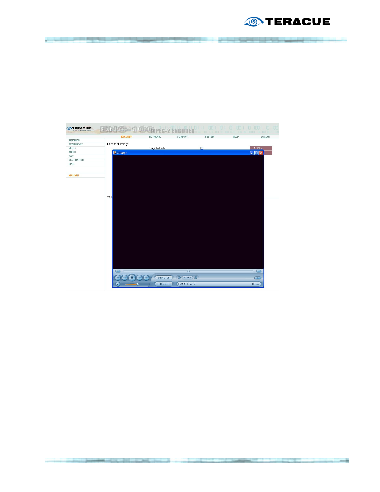
The menu XP
LAYER
starts the Standalone XPlayer, if a XPlayer is installed on the client PC. You
can start the XPlayer by clicking the XPlayer-Link inside the menu.
Afterwards the XPlayer automatically displays the stream of the ENC-100.
.!.
.!. .!.
.!. Requirement for this feature:
Requirement for this feature: Requirement for this feature:
Requirement for this feature: The
The The
The XPlayer must be installed
XPlayer must be installedXPlayer must be installed
XPlayer must be installed....
If the XPlayer is not installed on the client PC, the XPlayer-Link will have no function.
Page 50

50
2.5 Help
Clicking on the help button will open the Teracue ENC-100 user manual (this document)
directly from the Teracue website.
Your ENC-100 automatically connects to open the most current version of the user guide.
.!.
.!. .!.
.!. This
ThisThis
This will only work if the encoder is situated in a network in which internet access is
will only work if the encoder is situated in a network in which internet access is will only work if the encoder is situated in a network in which internet access is
will only work if the encoder is situated in a network in which internet access is
provided.
provided.provided.
provided. Otherwise "page not found" may be displayed.
Otherwise "page not found" may be displayed. Otherwise "page not found" may be displayed.
Otherwise "page not found" may be displayed.
Page 51
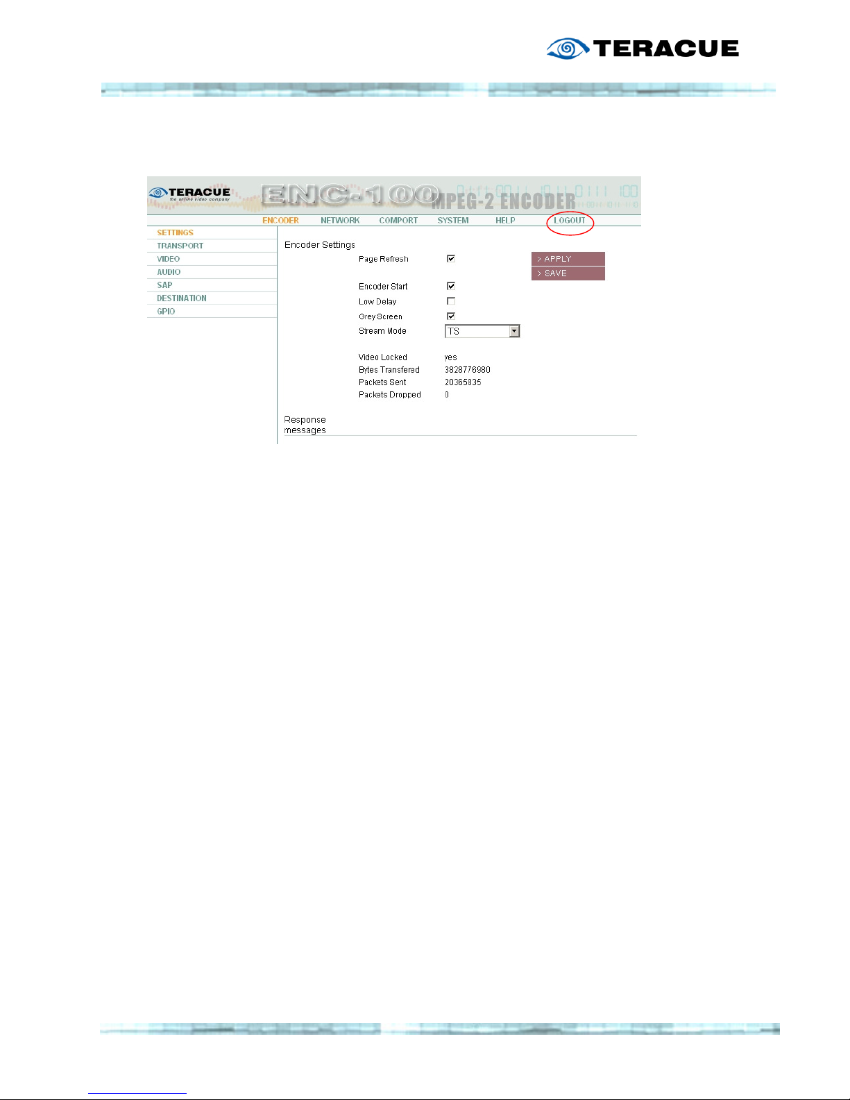
51
2.6 Logout
After having
made
adjustments
to the
encoder,
please be
sure to
logout.
.!.
.!..!.
.!.
Logging out prevents misuse and unauthorized access
Logging out prevents misuse and unauthorized access Logging out prevents misuse and unauthorized access
Logging out prevents misuse and unauthorized access to
toto
to the
the the
the ENC
ENCENC
ENC----100
100100
100....
Page 52
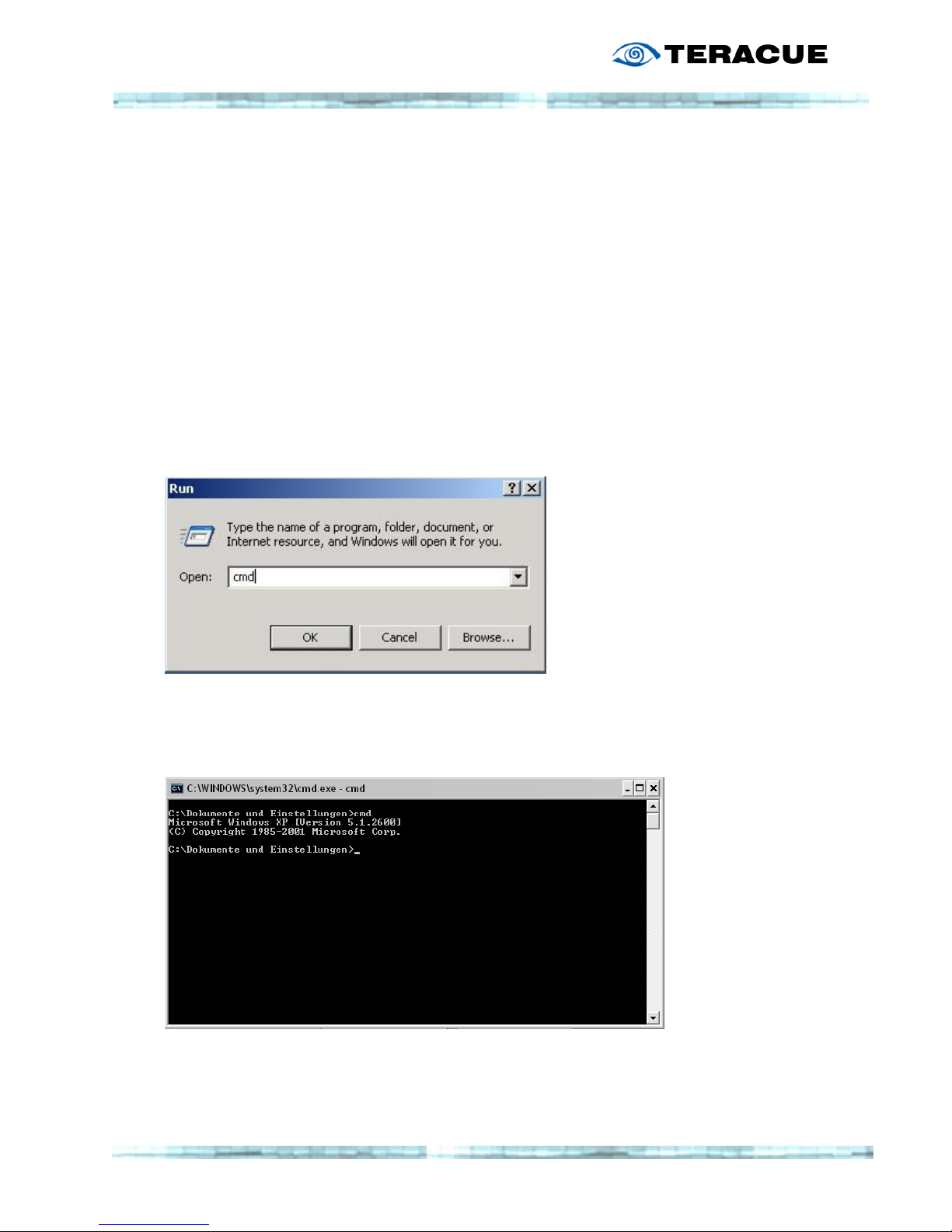
52
3. Extended Functions
3.1 Telnet
A further way to communicate with the ENC-100 blade instead of accessing it by a web
browser is to connect via telnet. Telnet is a terminal emulation program that runs on your
computer and connects your PC with the ENC-100 over the network.
To start a telnet session under windows you must open the commando prompt tool.
A practical way to open a command window within Windows explorer is to write
C:\Windows\system32\cmd.exe
Another way to open a new commando prompt is by choosing
Start
StartStart
Start
,
, ,
,
Run
RunRun
Run
. Then write "cmd
cmdcmd
cmd""""
and press the OK
OKOK
OK button.
In both cases the following window will open.
Page 53
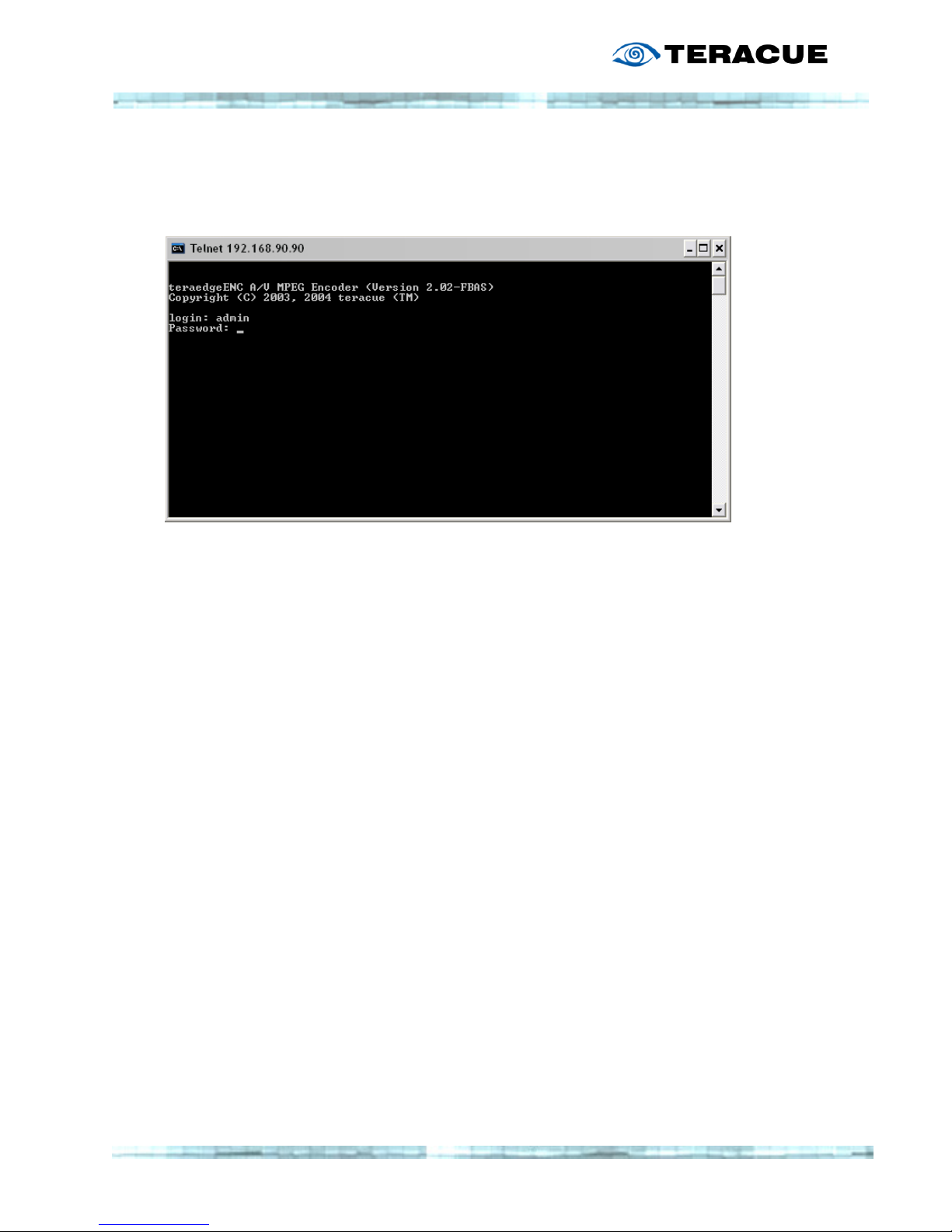
53
For starting a telnet session type: telnet <ip
telnet <iptelnet <ip
telnet <ip----address>,
address>,address>,
address>, e.g. telnet 172.16.20.100
The IP address should correspond to the ENC's IP address.
This will open the following dialog.
Enter your
Login Name
and
Password.
The same
password
as when
logging in
via browser
(admin/
admin)
After login: The command “help” will display a list of all available options.
The “ls”
“ls”“ls”
“ls” command allows you to see the available directories and options in the current
directory.
To change the current directory, write “cd
“cd“cd
“cd directory_name”””” e.g. “cd status”
If you want to enter the value of an option you must use the "put
putput
put"""" command followed by the
correct values. Afterwards use the """"apply
applyapply
apply"""" and "save"
"save" "save"
"save" commands to apply and/or save your
changes.
.!.
.!..!.
.!. Example
Example Example
Example
E.g. for changing the hostname, you need to type the following:
- put configuration/network/hostname teraedge
- apply configuration/network/hostname
- save
-reset
.!.
.!. .!.
.!. The following 2 pages provide an overview over the Telnet navigational and directory
The following 2 pages provide an overview over the Telnet navigational and directory The following 2 pages provide an overview over the Telnet navigational and directory
The following 2 pages provide an overview over the Telnet navigational and directory
structure. This overview is useful to find the co
structure. This overview is useful to find the costructure. This overview is useful to find the co
structure. This overview is useful to find the correct configuration settings when navigati
rrect configuration settings when navigatirrect configuration settings when navigati
rrect configuration settings when navigating
ngng
ng
in Telnet mode.
in Telnet mode.in Telnet mode.
in Telnet mode. For instructions and descriptions on the individual settings, please see the
For instructions and descriptions on the individual settings, please see the For instructions and descriptions on the individual settings, please see the
For instructions and descriptions on the individual settings, please see the
corresponding chapters for web based configuration.
corresponding chapters for web based configuration.corresponding chapters for web based configuration.
corresponding chapters for web based configuration.
Page 54
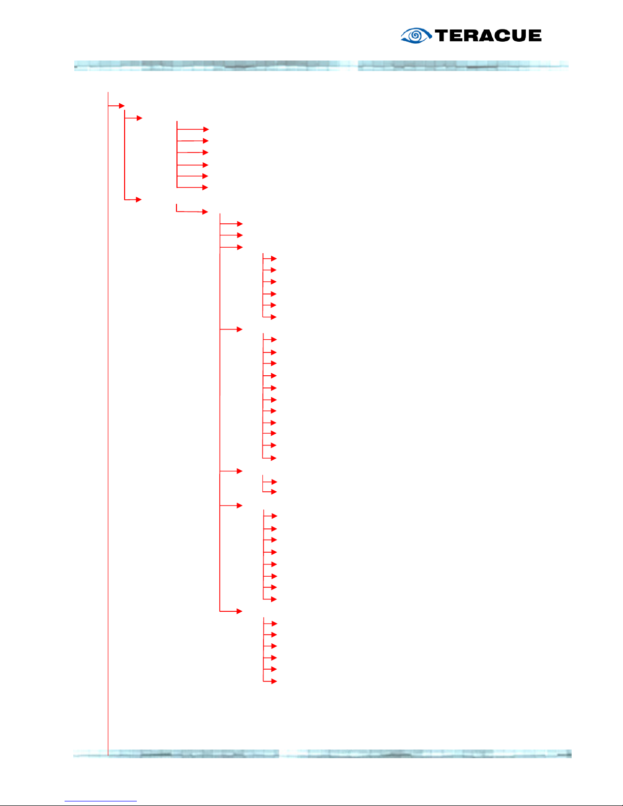
54
Configuration/
Configuration/Configuration/
Configuration/
Network/
Network/Network/
Network/
Ip_addr
Ip_addrIp_addr
Ip_addr IP-Address
subnet_mask
subnet_masksubnet_mask
subnet_mask Subnet Mask
broadcast_addr
broadcast_addrbroadcast_addr
broadcast_addr Broadcast Address
gateway_addr
gateway_addrgateway_addr
gateway_addr Gateway Address
hostname
hostnamehostname
hostname Hostname
linkmode
linkmodelinkmode
linkmode Link Mode
Encoder/
Encoder/Encoder/
Encoder/
0000////
start
startstart
start Encoder Start
low_delay
low_delaylow_delay
low_delay Low Delay
transpo
transpotranspo
transport/
rt/rt/
rt/
rate_control
rate_controlrate_control
rate_control Transport Rate Control
transport_rate
transport_ratetransport_rate
transport_rate Transport Rate (2000-16000)
actual_transport_rate
actual_transport_rateactual_transport_rate
actual_transport_rate Actual Transport Rate
video_pid
video_pidvideo_pid
video_pid Video PID (17-8190)
audio_pid
audio_pidaudio_pid
audio_pid Audio PID (17-8190)
pcr_pid
pcr_pidpcr_pid
pcr_pid PCR PID (17-8190)
video/
video/video/
video/
bitrate_type
bitrate_typebitrate_type
bitrate_type Bitrate Type (CBR, VBR)
vbr_target_bitrate
vbr_target_bitratevbr_target_bitrate
vbr_target_bitrate VBR Target Bitrate (1500-15000)
bitrate
bitratebitrate
bitrate Bitrate (2000-15000)
gop_type
gop_typegop_type
gop_type GOP Type (I, IP, IPB)
gop_dist
gop_distgop_dist
gop_dist GOP Distance (2, 3; IBP)
gop_l
gop_lgop_l
gop_len
enen
en GOP Length
format
formatformat
format Input Format (Pal, NTSC)
resolution
resolutionresolution
resolution Resolution (D1,2/3D1,1/2D1,SIF)
brightness
brightnessbrightness
brightness Brightness (0 - 255)
contrast
contrastcontrast
contrast Contrast (-128 – 127)
saturation
saturationsaturation
saturation Saturation (-128 – 127)
audio/
audio/audio/
audio/
ena
enaena
enable
bleble
ble Enable (On, Off)
bitrate
bitratebitrate
bitrate Bitrate (256, 384 kBit/s)
sap/
sap/sap/
sap/
transmit
transmittransmit
transmit Transmit (On, Off)
retransmit_time
retransmit_timeretransmit_time
retransmit_time Retransmit Time (1 - 1000)
time_to_live
time_to_livetime_to_live
time_to_live Time To Live (1 – 255)
session_name
session_namesession_name
session_name Session Name
se
sese
session_description
ssion_descriptionssion_description
ssion_description Session Description
keywords
keywordskeywords
keywords Keywords
author
authorauthor
author Author
copyright
copyrightcopyright
copyright Copyright
network/
network/network/
network/
destination_ip_addr
destination_ip_addrdestination_ip_addr
destination_ip_addr Destination IP-Address
destination_port
destination_portdestination_port
destination_port Destination Port (0 - 65535)
transmit_mode
transmit_modetransmit_mode
transmit_mode Transmit Mode
time_to_live
time_to_livetime_to_live
time_to_live Time To Live (1 – 255)
join_own_multicast
join_own_multicastjoin_own_multicast
join_own_multicast Join Own Multicast (On, Off)
packet_size
packet_sizepacket_size
packet_size Packet Size
Page 55

55
status/
status/status/
status/
system/
system/system/
system/
software_version
software_versionsoftware_version
software_version Software
uptime
uptimeuptime
uptime System uptime
cpuload
cpuloadcpuload
cpuload CPU Load
temperature
temperaturetemperature
temperature Temperature
3.3Vin
3.3Vin3.3Vin
3.3Vin 3.3 V in
5.0Vin
5.0Vin5.0Vin
5.0Vin 5.0 V in
mac_address
mac_addressmac_address
mac_address Mac Address
encoder/
encoder/encoder/
encoder/
o/
o/o/
o/
version
versionversion
version Encoder
(chapter: 2.4.8)
video_locked
video_lockedvideo_locked
video_locked Video Locked
(chapter: 2.4.1)
bytes_transfered
bytes_transferedbytes_transfered
bytes_transfered Bytes Transferred
(chapter: 2.4.1)
packets_sent
packets_sentpackets_sent
packets_sent Packets Sent
(chapter: 2.4.1)
packets_dropped
packets_droppedpackets_dropped
packets_dropped
delay_restarts
delay_restartsdelay_restarts
delay_restarts
Page 56
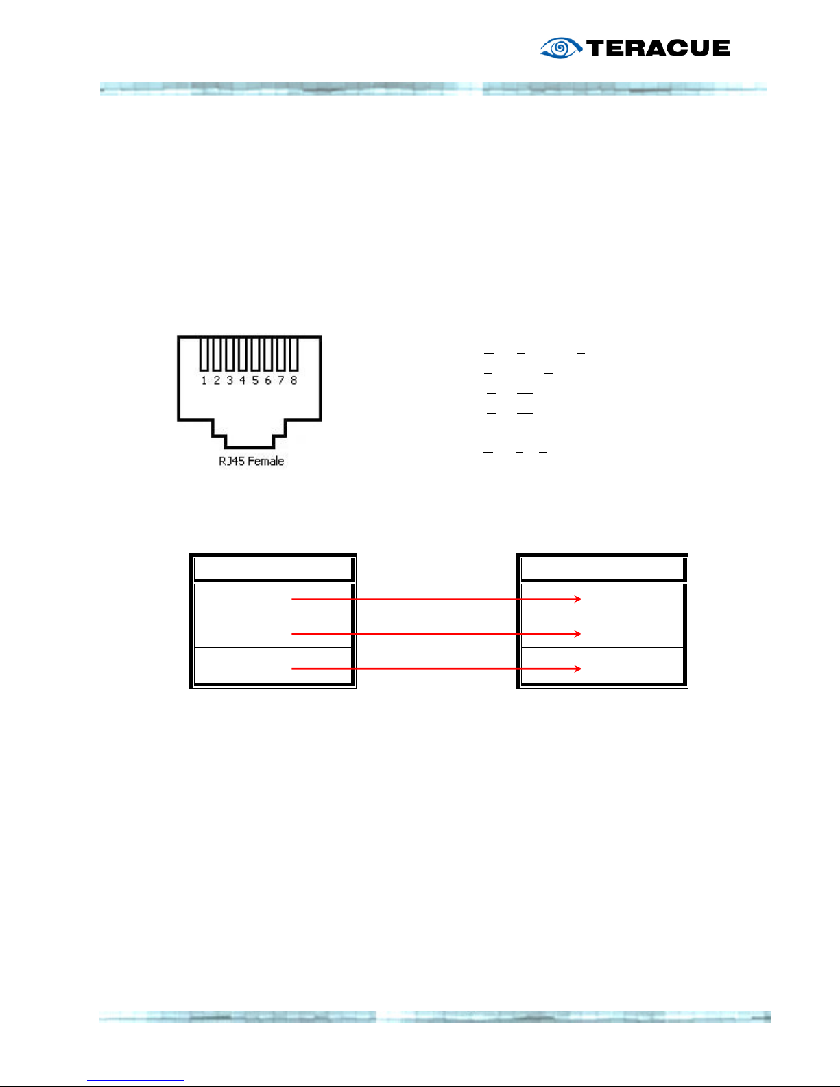
56
3.2 Serial Connection
Another possibility to connect with the encoder is with a serial connection. Therefore you
need the ENC-100 com-cable (ENC-100-COMCAB). The com-cable is an optional ENC
accessory, and needs to be ordered separately.
For more information contact: [email protected]
The pin assignment for the RJ45 female COM-port interface of the ENC-100 is:
Pin 1: not connected
Pin 2: DTR (Data Terminal Ready)
Pin 3: TxD (Transmit Data)
Pin 4: GND (Ground)
Pin 5: GND (Ground)
Pin 6: RxD (Receive Data)
Pin 7: DSR (Data Set Ready)
Pin 8: not connected
The ENC-100-COMCAB cable assignment for a connection between a computer and the
ENC-100 is:
D-Sub 9 Pin connector
RJ 45 connector
Pin 2
Pin 3
Pin 3
Pin 6
Pin 5
Pin 5
Connect your ENC-100 via the ENC-100-COMCAB to the serial port of your computer.
Open the Hyper Terminal application. Hyper Terminal is a communication software which is
included with Microsoft Windows. To run Hyper Terminal click Start/Accessories. Within
accessories double click Hyper Terminal (If you do not see Hyper Terminal click the
communications folder and then click Hyper Terminal).
Is connected with
Is connected with
I
s connected with
Page 57
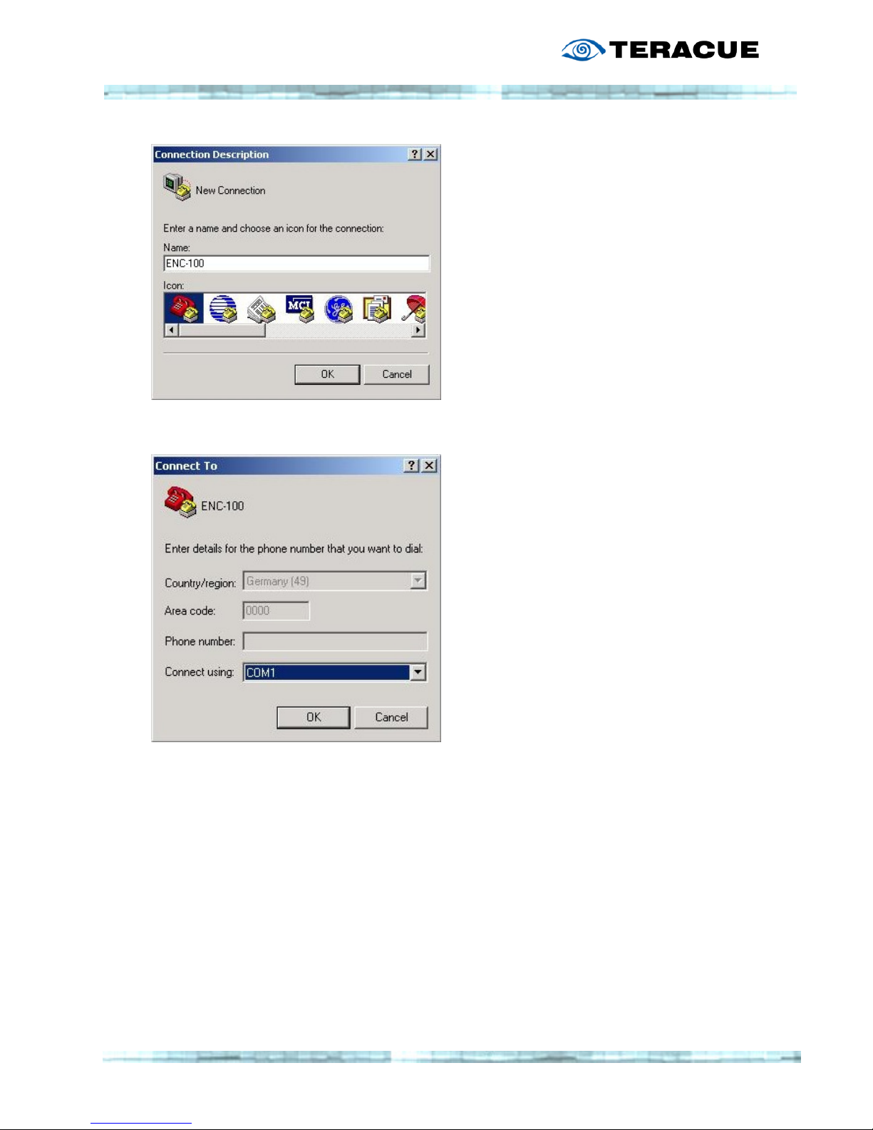
57
When Hyper Terminal is started you will be
presented with the “Connection Description”
“Connection Description”“Connection Description”
“Connection Description”
dialogue box. Type in a session name (e.g.
ENC-100) and click OK
OKOK
OK.
After the “Connect
“Connect “Connect
“Connect To
ToTo
To”
” ”
” window will open, click
on the arrow for the “Connect Using” drop
down box and select the COM Port (the COM
Port you’re using to connect the ENC-100.
Afterwards click OK
OKOK
OK.
This will open the “COM port
“COM port “COM port
“COM port PPPProperties”
roperties” roperties”
roperties” dialogue box:
Page 58
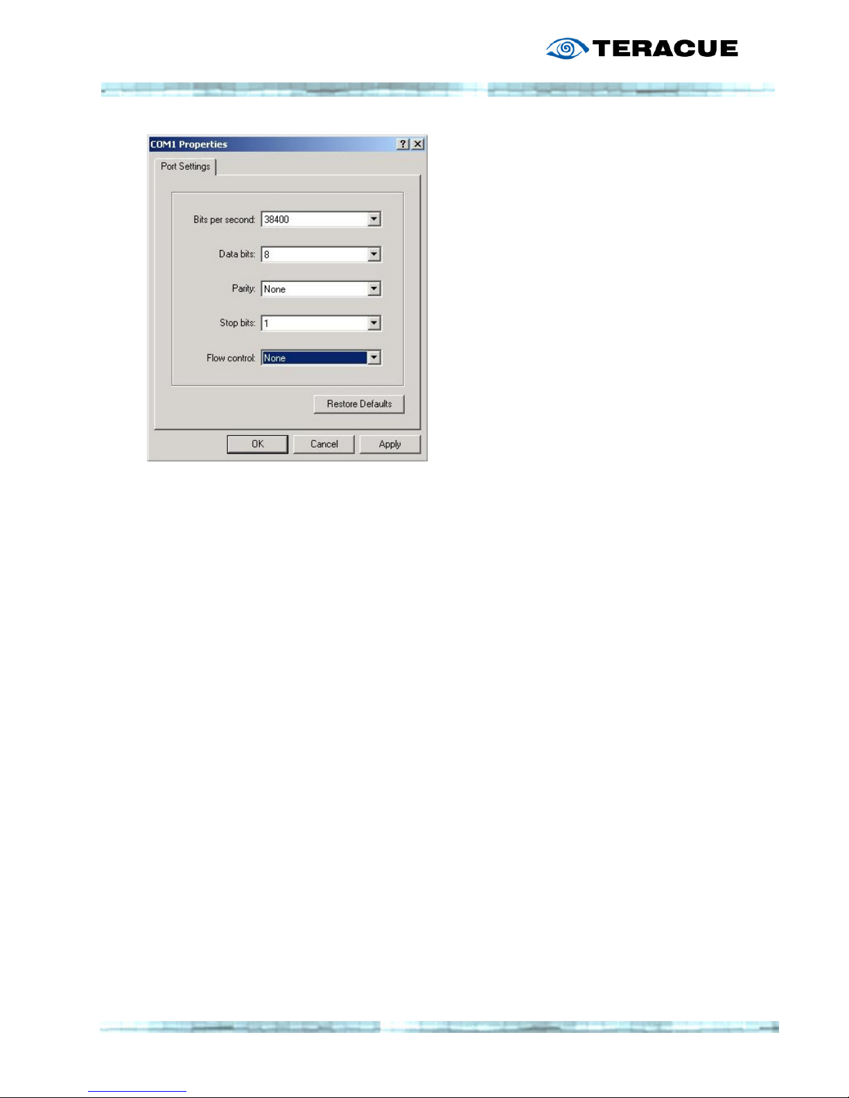
58
Adjust the following attitudes for a successfully
connection.
Bits per second: 38400
Data bits: 8
Parity: None
Stop bits: 1
Flow control: None
Click OK
OKOK
OK.
Now start or restart your ENC-100. Afterwards you will see the following screen:
Page 59
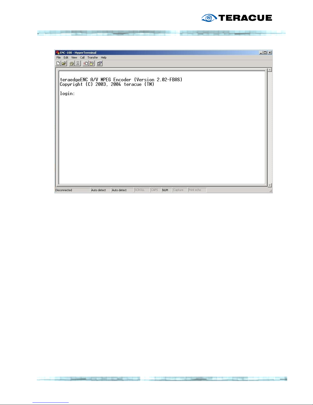
59
Enter your Login Name and Password.
(The same password as during the registration in the browser: admin/admin)
The structure of directories and options are the same as at the Telnet connection
(chapter 3.1),
so you have to use the same commands for changing and applying values.
.!.
.!. .!.
.!. Lost or forgotten
Lost or forgottenLost or forgotten
Lost or forgotten IP
IPIP
IP----Address:
Address: Address:
Address:
If you have forgotten the ENC's IP-Address and cannot retrieve it using the Teraplay
application, then you can use the serial connection to find the current IP Address.
Open Hyper Terminal to create a serial connection to your ENC-100.
Type in your Login Name and Password and press enter (admin/admin).
The IP-Address is in the submenu Network directory.
Type “cd configuration
“cd configuration“cd configuration
“cd configuration/n
/n/n
/network”
etwork”etwork”
etwork” + “ls”
“ls”“ls”
“ls”.
Now you will see all the ENC's network options. The line states the IP-Address of your
encoder.
Page 60

60
3.3 Audio Talkback
The audio output on the ENC-100 operates as an audio decoder. It enables operating the
ENC-100 in Full Duplex Audio. The ENC-100 can therefore be used for audioconferencing
environments, where viewers of the encoded live streams are to be able to ask questions and
communicate with people on the encoding side.
For example an encoder can be set up to encode video and audio from a camera that is
installed at an entrance (security application). The person who wants to enter speaks into a
microphone to state his/her name, etc. This would be normal operation with a one-way
communication (simplex mode).
Example 1:
Example 1:Example 1:
Example 1:
By using the encoder's audio output, a receptionist/security officer is able to talk back
to the person, e.g. arguing why access is denied or that the person should hold its ID
into the camera. This represents regular two-way communication (Full Duplex Mode).
Example 2:
Example 2:Example 2:
Example 2:
Another application where Full Duplex Audio is necessary is when students from
classrooms or large auditoriums are to communicate with doctors or surgeons inside
operation rooms or other sealed environments. With the ENC-100's Talkback option
students or monitoring staff are able to ask on the spot questions and communicate
and learn in real-time.
To use the Talk Back function on the encoder, you need the following utility:
""""ENC
ENCENC
ENC----TALKBACK
TALKBACKTALKBACK
TALKBACK....zip
zipzip
zip"
" "
" –––– You will find the Zip-folder in the IPTV support Area on
www.teracue.com, inside the Encoder support section.
The ENC-TALKBACK.zip includes the following files:
- audioplugin.ocx: ActiveX control
- install.bat: Installation file
- audio_test.html Example HTML-Page
The audioplugin.ocx is designed as an ActiveX control, so you can simply embed and run it
from a HTML-Page. Currently ENC-Talkback can only be run from inside Internet Explorer.
You can find an easy example of such a Webpage inside the zip file..
To install the audioplugin.ocx please execute the install.bat. The ActiveX control is now
installed.
To run the ActiveX component, it needs to be executed from a HTML-Page.
Page 61
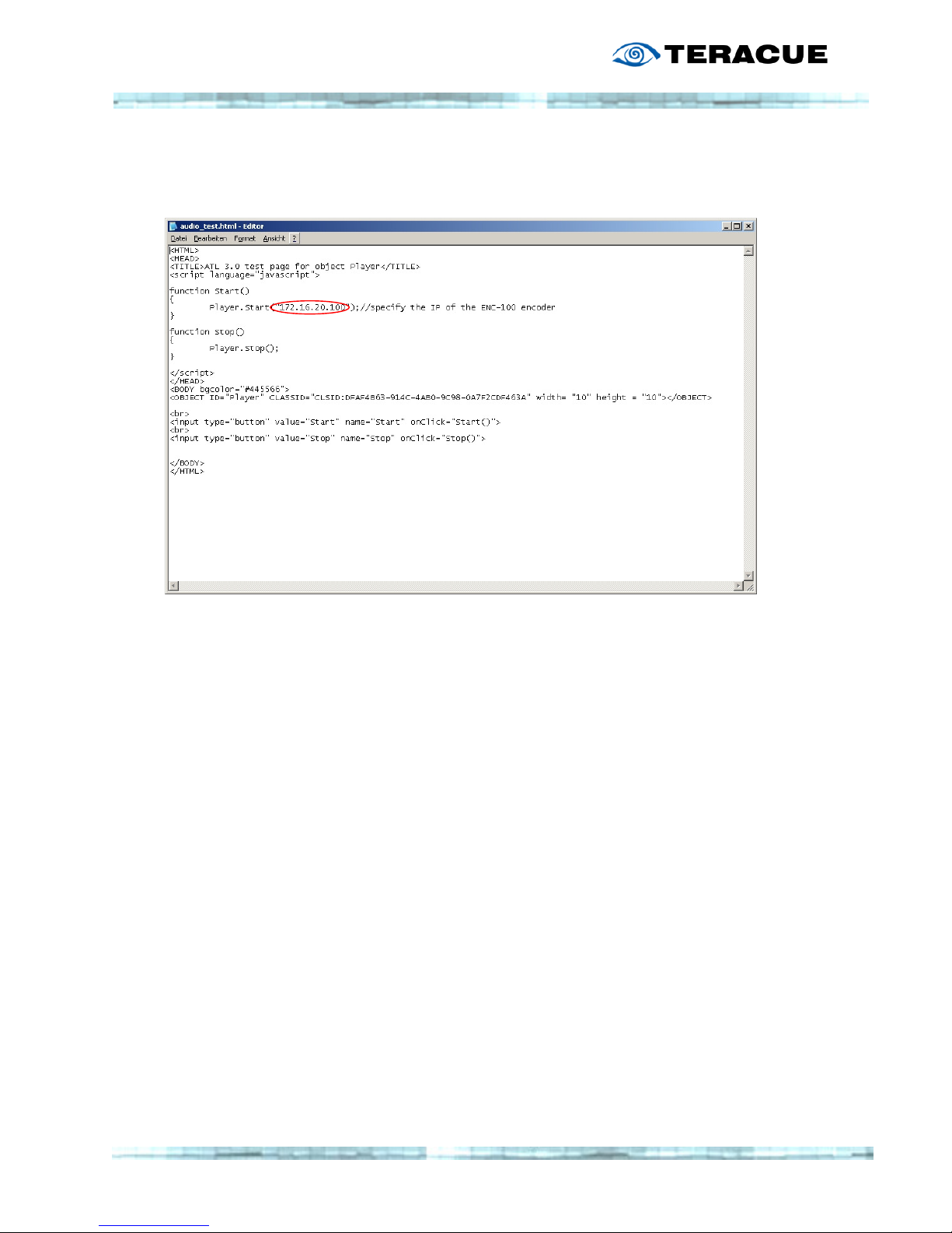
61
To change the IP Address (e.g. 172.16.100.100) of the encoder, to which you would like to
send your microphone audio signals, open the attached Webpage (audio_test.html or
index.html) in a text editor.
The audio signals from the microphone that is connected to your PC will be sent and output
on the ENC-100 on the analog audio output.
In order to talk back to the encoder, please be sure that you have a microphone or another
audio signal connected to your PC.
Please check if it is working correctly and see if the microphone level adjustment is correct
adjusted under
CONTROL PANEL>SOUND SETTINGS
. Be sure that the
MIC
levels are set accordingly
and that the option for turning the
MIC OFF
is not checked.
If your regular PC speaker volume settings are OK, then you should be able to hear yourself,
when you talk into the microphone. Please be aware that if your regular volume setting is too
high, you might experience extremely loud high-pitched feedback signals and disturbing
echoes. So it is a good idea to start with a low volume level for the regular PC volume setting.
If you are sure that your microphone and microphone input is working, simply press the
S
TART
button on the example HTML-Page. If you have active speakers connected to the
ENC-100 audio output, then your microphone signals will be output there.
The ENC-100 has a stereo mini jack, but it provides the same signal (mono) on both
(left/right) channels.
Furthermore the sampling frequency of the audioplugin.ocx for talkback to the ENC-100 is
22,050Hz, which is half CD-quality and therefore less appropriate to stream music.
Page 62
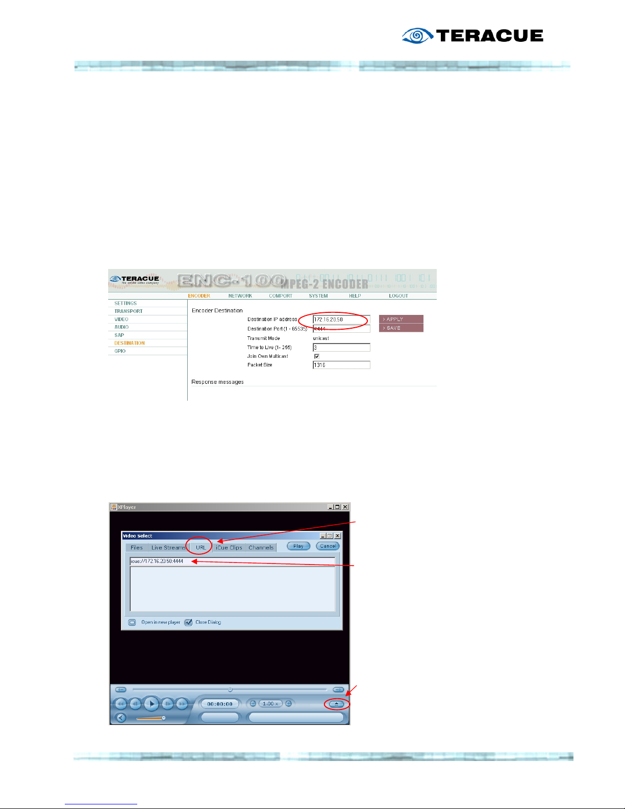
62
3.3.1 Unicast Stream to XPlayer
The ENC-100 can not only stream by multicast. You can also choose unicast to stream to a
single destination. To view the unicast stream you can use the XPlayer. Just follow the next
instructions.
ENC-100: Go to Encoder > Destination
Enter the IP address of your PC, where the XPlayer is installed, as “Destination IP address”.
Press “Apply” and “Save”. The Encoder will show “unicast” as “Transmit Mode”. You can leave
the other settings on default.
Open the XPlayer and choose the “Video Select” window. Click on “URL” and enter icue://
followed by the IP address of your PC with the port number you entered on the ENC-100.
E.g.: icue://172.16.20.50:4444. After you entered the IP address just press “Play”.
.!. The XPlayer has to be installed on the PC you entere
.!. The XPlayer has to be installed on the PC you entere.!. The XPlayer has to be installed on the PC you entere
.!. The XPlayer has to be installed on the PC you entered as
d as d as
d as ddddestination
estinationestination
estination in the ENC
in the ENC in the ENC
in the ENC----100 menu
100 menu100 menu
100 menu
Choose URL
Enter the URL of the unicast Stream
E.g.: icue://172.16.20.50:4444
Open “Video Select” window
Page 63

63
3.3.2 Multicast Stream to XPlayer
To open a Multicast Stream manually you can enter the following string under “URL” in the
“Video Select” window of the XPlayer. (see previous page)
Enter icue:// followed by the Multicast IP address of the Stream with the corresponding port
number.
E.g.: icue://239.252.90.90:4444
After you have entered the IP address simply press “Play”.
Page 64
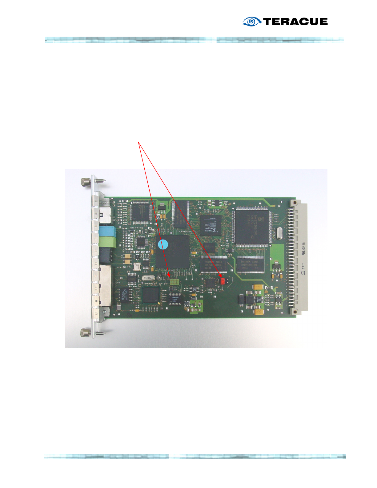
64
3.4 Resetting to factory defaults
The ENC-100 blade can easily be returned to its factory default values (IP 172.16.20.100).
In order to do this please power down the encoder chassis and remove the blade gently and
carefully from the chassis.
1. Hold the blade as shown below, with the video input pointing to the left.
Locate the green pin connector marked below.
Remove the red RS-232 jumper and place it on the left pair of the green pins.
2. Insert the ENC-100 blade gently into the chassis and turn the power on.
Wait for 2 minutes. Your encoder blade has been returned to its factory defaults.
3. To operate the ENC-100 again, power down the chassis and carefully remove the blade
once more. Return the red jumper to its original position, i.e. onto the left pin pair of the
black pin field. As shown in the photo above.
Page 65

65
4. CE, FCC conformance
The ENC-100 is labeled with the CE and FCC seal.
The ENC-100 is in conformity with the following
standards:
EN 55103-1 Electromagnetic Interference - Product Family Standard for
Audio, Video, Audio-Visual and Entertainment Lighting Control
Apparatus for Professional use - Part 1: Emissions
EN 55103-2 Electromagnetic Susceptibility - Product Family Standard for
Audio, Video, Audio-Visual and Entertainment Lighting Control
Apparatus for Professional use - Part 2: Immunity
EN 55022 Limits and Methods of Measurement of Radio Interference
Characteristics of Information Technology Equipment
5. Restriction of Hazardous Substances Directive
(RoHS)
The ENC-100 is manufactured according to the RoHS Directive. The Directive on the
Restriction of Hazardous Substances in Electrical and Electronic Equipment (RoHS) has been
passed as a law by the European Union. It affects manufacturers, sellers, distributors and
recyclers of electrical and electronic equipment containing hazardous substances as lead,
cadmium, mercury, hexavalent chrome, polybrominated biphenyl (PBB) and polybrominated
diphenyl ether (PBDE).
After July 1, 2006 the use of these materials will be banned in new products sold in Europe.
Since beginning of 2005, Teracue AG began the process of redesigning and converting all of
Since beginning of 2005, Teracue AG began the process of redesigning and converting all of Since beginning of 2005, Teracue AG began the process of redesigning and converting all of
Since beginning of 2005, Teracue AG began the process of redesigning and converting all of
its products to not contain any of the listed materials. All new products sold b
its products to not contain any of the listed materials. All new products sold bits products to not contain any of the listed materials. All new products sold b
its products to not contain any of the listed materials. All new products sold by Teracue will
y Teracue will y Teracue will
y Teracue will
be fully RoHS
be fully RoHSbe fully RoHS
be fully RoHS----compliant by July 1, 2006.
compliant by July 1, 2006.compliant by July 1, 2006.
compliant by July 1, 2006.
Page 66

66
6. Waste Electrical and Electronic Equipment
Directive (WEEE)
The WEEE Directive has been passed to reduce waste arising from
electrical and electronic equipment. It encourages reuse, recycling and
other forms of recovery. Customers and end-users of electronic
equipment in the EU can therefore play an important role in reducing
WEEE and saving the environment by separating out WEEE and disposing
of it properly.
Teracue AG is a registered WEEE parti
Teracue AG is a registered WEEE partiTeracue AG is a registered WEEE parti
Teracue AG is a registered WEEE participant since 2004. Within Germany,
cipant since 2004. Within Germany, cipant since 2004. Within Germany,
cipant since 2004. Within Germany,
Teracue is registered under the WEEE Number: DE10642708.
Teracue is registered under the WEEE Number: DE10642708. Teracue is registered under the WEEE Number: DE10642708.
Teracue is registered under the WEEE Number: DE10642708. German
customers and end-users are required to discard products marked with the WEEE symbol
(crossed out trash bin) at local resource collection points. Do not dispose products marked
with the WEEE symbol in domestic refuse.
Every country within the EU has defined different directives and methods for the collection of
electronic materials to ensure the WEEE Directive. Please follow the national guidelines that
have been identified for your country. For more information about waste disposal of your old
electrical and electronic equipment, please contact your local city office, your waste disposal
service or the company where you bought the product.
Page 67

67
7. Technical Specifications
ENC-100 Models
ENC-100-COMP MPEG-2 encoder blade with COMPOSITE input
ENC-100-YC MPEG-2 encoder blade with Y/C, S-Video input
ENC-100-SDI MPEG-2 encoder blade with SDI Video input
Encoding Specifications
Encoding SpecificationsEncoding Specifications
Encoding Specifications
Standards: PAL, NTSC
Video Inputs: Dependent on ENC-100 model
Composite: 1V, 75 Ohm (BNC), S-Video: 1V, 75 Ohm (miniDIN),
SDI Input (BNC)
Video Resolutions: Full D1: 720h x 480/576v, Half-D1: 384h x 480/576v, CIF/SIF:
384h x 240/288v
Audio Inputs: Analog Stereo, Line level 3.5mm jack
Audio Outputs (Talkback): Analog Stereo, Line level 3.5mm jack
MPEG-2 Video Coding: MPEG-2, ML@MP, 4:2:0
Stream types: ISO/IEC 13818-1 Transport
ISO/IEC 13818-2,3
Elementary A/V
Video encoding bitrates: 800Kb/s – 15Mb/s (CIF/SIF min. 800Kbit/s, Full D1 min.
2Mbit/s)
MPEG-2 Audio Encoding: MPEG-1, Layer 2
I/O S
I/O SI/O S
I/O Specifications
pecificationspecifications
pecifications
Network: 10/100TX Ethernet, RJ45, half/full duplex, Auto-sensing
Streaming traffic: Unicast and Multicast traffic supported
IP Protocols: HTTP (Web Browser), TCP/IP Control Protocol, UDP/IP
Streaming, IGMPv2, Supports SAPv1, SNMP
RS-232/485 port: Remote control for non IP devices via TCP/IP RS-232/485
command tunneling
GPI: 1 INPUT, for device control: streaming on/off configuration
EEEEnvironmental
nvironmentalnvironmental
nvironmental
Humidity: Up to 80%, non-condensing
Temperature: 0 to +65°C environment temperature; fanless when operated in
FR-100 chassis
Weight: Approx. 150 gramms per blade
Blade dimensions (H/W/D): 20mm x 130mm x 190mm
Power: 5W per blade
Page 68

68
Chassis:
Chassis:Chassis:
Chassis:
FR-100 Single channel ENC-100 chassis, 5V DC, 10W, 100-240V AC ext. power
supply included
Dimensions (H/W/D): 45mm x 145mm x 240mm, Weight: 650 gramms
No forced cooling required (fanless)
FR-1000 High-density, multichannel ENC-100 chassis, holds max. 21 ENC-100
blades, Max. 150W with 21 blades, 90-240V AC internal SINGLE
supply.
Dimensions (H/W/D): 176(4RU) x 480 x 400 mm, Weight: 8,5 kg
(empty)
FR-2000 High-density, multichannel ENC-100 chassis, holds max. 21 ENC-100
blades, Max. 150W with 21 blades, 90-240V AC internal DUAL,
REDUNDANT power supply.
Dimensions (H/W/D): 176(4RU) x 480 x 400 mm, Weight: 9,5 kg
(empty)
FR-PLATE-1/3 FR-1000/2000 covering plate for empty ENC-100 slots: -1 covers 1
ENC slot, -3 covers 3 ENC slots
Page 69

69
8. Known Issues
1. GPIO OUT support will be added in a future firmware release.
2. When encoding a Transport Stream with audio only, users may experience an issue
regarding audio drop outs every 80 seconds.
 Loading...