

Page 1
Page 2

1. Short description
TCW280 is an analog output module with Ethernet interface and galvanic isolation between power
supply and outputs.
It has 2 analog output channels. Every channel can work either in voltage (0/5 or 0/10V) or current loop
(0/20, 4/20 or 0/24mA) mode. Generated signals have excellent stability and 12-bit resolution.
The device has also 4 digital (open drain) outputs. The digital outputs work in two modes – ON/OFF or
PWM. In ON/OFF mode they can be used as a standard digital output to control devices with dry contact
activation. In the PWM mode, the output can be used as an “analog” output for appropriate processes
– DC motor control, LED dimming, etc. The frequency in PWM mode can be up to 2 kHz.
TCW280 has also 2 relays with normally closed and normally open contacts. Both relays can be activated
from the WEB interface, M2M protocol or by the schedule.
The scheduling functionality offers 4 different schedules for single or repeated (weekly) tasks.
The module supports MODBUS TCP/IP, SNMP, and HTTP API for M2M communication.
2. Features
• Galvanically isolated outputs;
• 10/100 Mbit Ethernet connectivity;
• Password protected WEB interface;
• 2 analog outputs with voltage and current loop modes;
0/20, 4/20 and 0/24mA ranges for current loop mode of analog output;
•
0/5 or 0/10V ranges for voltage mode of analog output;
•
• 4 digital (open drain) outputs with ON/OFF or PWM modes;
• 2 relays with NO and NC contacts;
• Dynamic DNS support;
• 4 schedules with single and weekly mode;
• NTP support;
• SNMP v2 support;
• SNMP traps to up to 5 recipients;
• MODBUS TCP/IP support;
• Periodical HTTP post with current status in XML or JSON file to the remote server;
• HTTP API commands in server and client mode;
• HTTP Post to up to 3 different servers;
• Back/restore of settings for easy device multiplication;
• Firmware update over the Internet;
• DIN-Rail/wall-mountable enclosure.
3. Applications
The possible application of TCW280 are:
• Direct electronic valve actuators control;
• DC motor speed control;
• Direct dimming of RGB LED’s;
• Variable frequency drive control;
• Solenoid valve control;
• Solid state relay control;
• Remote transmission (tunneling) of analog signals.
TCW280_R1.2 – February 2019 Page 2
Page 3

4. Specifications
• Physical characteristics
Dimensions: 115 x 90 x 40 mm
Weight: 170 g
Mounting: wall and DIN rail
• Environmental limits
Operating Temperature: -10 to 55°C
Storage Temperature: -20 to 70°C
Ambient Relative Humidity: 10 to 80% (non-condensing)
• Standards and Certifications
Safety: EN 60950-1:2006+A11:2009+A1:2010+A12:2011+A2:2013
EMC: EN 55032:2015, EN 55024:2010+A1:2015, EN 61000-3-2:2014, EN 61000-3-3:2013
RoHS: Compliant
• Warranty
Warranty period: 3 years
• Power requirements
Input Voltage: 10 to 32 VDC
Input Current: 220 mA @ 12 VDC (all relays are on and both analog outputs are at 24mA)
• Analog outputs
Isolation: Isolated (1000V)
Type: Single ended
Resolution: 12 bits
Mode: Voltage or Current loop (WEB interface selectable)
Ranges: 0/5V, 0/10V, 0/20mA, 4/20mA, and 0/24mA
Accuracy: ±1%
• Digital outputs
Isolation: Isolated (1000V)
Type: Open drain
Maximum drain voltage: 24VDC
Maximum drain current: 0.3A
Mode: ON/OFF or PWM (WEB interface selectable)
PWM resolution: 10 bits
PWM frequencies: 1, 5, 10, 50, 100, 500, 1000, and 2000 Hz
• Relay outputs
Type: Form C (N.O. and N.C. contacts)
Contact current rating: 0.5 A @ 24 VDC, 30 VAC (resistive load)
Initial insulation resistance: 100 mega-ohms (min.) @ 500 VDC
Mechanical endurance: 10 000 000 operations
Electrical endurance: 100 000 operations @ 0.5 A resistive load
Contact resistance: 100 milli-ohms max. (initial value)
Pulse output: 0.1 Hz at rated load
• Internal FLASH memory
Endurance: 100 000 cycles (Every relay status and settings change is a memory cycle.)
TCW280_R1.2 – February 2019 Page 3
Page 4

5. Installation and setup
This device must be installed by qualified personnel.
This device must not be installed directly outdoors.
The installation consists of mounting the device, connecting to an IP network, connecting inputs and
outputs, providing power and configuring via a web browser.
5.1. Mounting
TCW280 should be mounted in a clean and dry location on a not flammable surface. Ventilation is
recommended for installations where the ambient air temperature is expected to be high.
Mount the device to a wall by using two plastic dowels 8x60mm (example Würth GmbH 0912 802 002)
and two dowel screws 6x70mm (example Würth GmbH 0157 06 70). Attach the screws to the surface
vertically. See Appendix-A, fig. 1 for mechanical details.
Maintain spacing from adjacent equipment. Allow 50 mm of space on all sides, as shown in fig.2 in
Appendix A, this provides ventilation and electrical isolation
TCW280 can be mounted to a standard (35mm by 7.55mm) DIN rail. Attach the controller to the DIN
rail by hooking the hook on the back of the enclosure to the DIN rail and then snap the bottom hook
into place.
5.2. LED indicators
The following indicators show the status of the controller:
• Relay1/Relay2 (green) – these LEDs are illuminated whenever the corresponding relay is
activated (the NO contact is closed and the NC contact is open);
• PWR (red) – in working mode shines, blinks together with STS if there is a hardware error;
• STS (yellow) – flashes when the main program of the controller is executed;
• NET (orange) – network status - ON when a link is established, blinks if there is an activity.
5.3. Connections
Attention! Disconnect power supply before wiring.
The correct wiring procedure is as follows:
• Make sure power is turned off;
• Make wiring connections to the terminals;
• Apply power.
It is recommended to test and configure TCW280 without any controlled device. In this case,
unexpected turn on will be avoided.
Make sure that wires are properly attached to the terminals and that the terminals are tightened.
Not proper wiring and configuration can cause permanent damage to TCW280 or the equipment to
which it is connected or both.
TCW280_R1.2 – February 2019 Page 4
Page 5
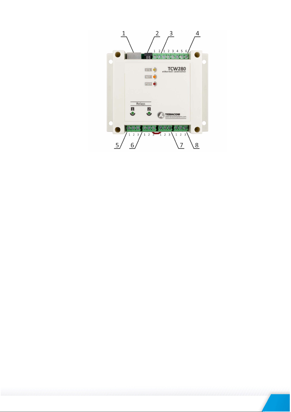
Inputs and outputs locations are shown below:
Connector 1
Ethernet - RJ45
Connector 5
Pin1 – Relay1-NC
Connector 2
Power - 2.1x5.5mm connector
(central positive)
Pin2 – Relay1-COM
Pin3 – Relay1-NO
Connector 3
Pin1 – Power positive
Connector 6
Pin1 – Relay2-NC
Pin2 – Power negative (GND)
Pin2 – Relay2-COM
Connector 4
Pin1 – Open drain OUT4
Pin3 – Relay2-NO
Pin2 – SGND
Connector 7
Pin1 – IOUT1
Pin3 – Open drain OUT3
Pin2 – SGND
Pin4 – Open drain OUT2
Pin3 – VOUT1
Pin5 – SGND
Connector 8
Pin1 – IOUT2
Pin6 – Open drain OUT1
Pin2 – SGND
Pin3 – VOUT2
5.3.1. Power supply connection
TCW280 is designed to be supplied by adapter SYS1308-2412-W2E or similar, intended for use in
the conditions of overvoltage category II. The power supply equipment shall be resistant to short
circuit and overload in a secondary circuit.
When in use, do not position the equipment so that it is difficult to disconnect the device from the
power supply.
5.3.2. Analog outputs
TCW280 has two isolated analog channels. Every channel can be programmed to work either in
voltage or current loop mode. In the voltage mode, two ranges are supported - 0 to 5 and 0 to 10
volts. In the current loop mode, three ranges are supported – 0 to 20, 4 to 20, and 0 to 24 mA. In
the current loop mode, there is an alarm notification for open loop.
Voltage and current loop outputs are single-ended and are assigned to different connectors. Using
the selected mode requires connecting to the appropriate connector.
TCW280_R1.2 – February 2019 Page 5
Page 6
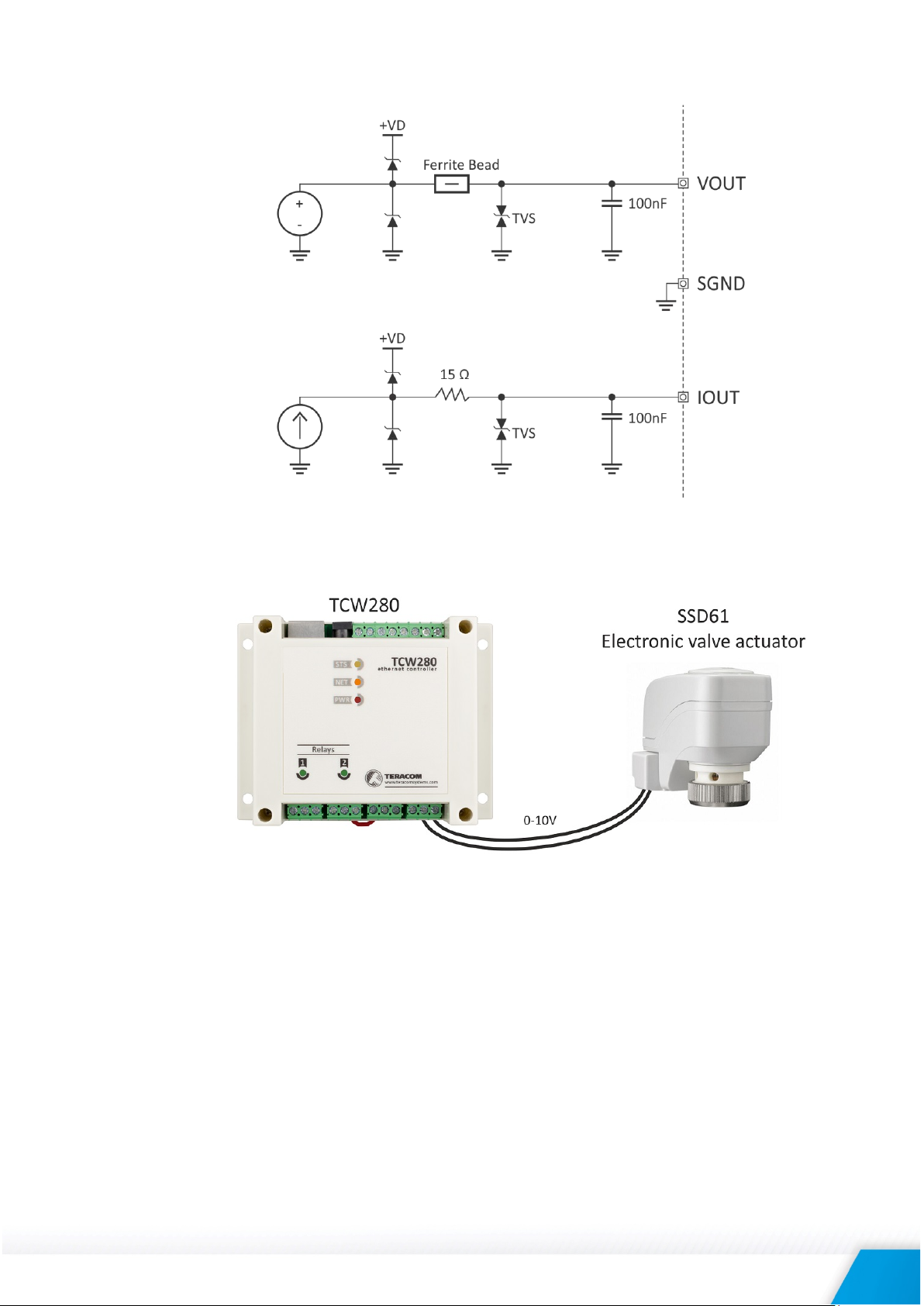
The output schematic is as follows:
Analog inputs can be used to direct control of devices with voltage or current loop inputs –
electronic valve actuators, motor inverters, etc.
5.3.3. Open drain outputs
TCW280 has four isolated open drains (digital) outputs. Every digital output can be programmed
to work either in ON/OFF or PWM (Pulse-width modulation) mode.
In PWM mode a few frequencies are supported. The working frequency of PWM has to be higher
than the effect which is expected in the load. Every output can be set on a different Pulse-width,
but the frequency is the same for all outputs in this in this mode.
PWM is an easy way to have an analog control through a digital signal. The duty cycle of the PWM
corresponds to the average value of voltage fed to the load.
TCW280_R1.2 – February 2019 Page 6
Page 7
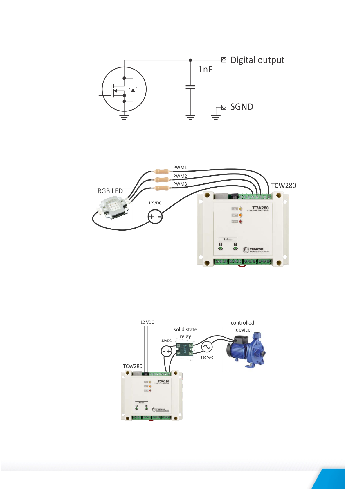
The output schematic is as follows:
The open drain outputs in PWM mode can be used for control dimming of LEDs, speed control of
PMDC motor, control the angle of servo motors, etc.
The open drain outputs in ON/OFF mode can be used as a standard digital output. They can control
directly the “dry contact” inputs of the controlled device. For high current loads, external solid
state relay or mechanical relay should be used.
TCW280_R1.2 – February 2019 Page 7
Page 8

5.3.4. Relays connection
TCW280 has 2 relays. They can be used for switching on or off electrical and electronic devices.
The relay contacts are internally connected directly to the terminal connectors. For both relays
normally open, normally closed and common contacts are available. For loads with higher
switchable current/voltage than specified, an external relay should be used.
When mechanical relays switch inductive loads such as motors, transformers, relays, etc., the
current will arc across the relay contacts each time the contacts open. Over the time, this cause
wears on the relay contacts which shorten their life. When switching an inductive load, it is
recommended that relay contact protection devices are used.
5.3.5. Network connection
The Ethernet port of TCW280 should be connected to 10/100 Base-T Ethernet hub, switch or
router.
For configuration, TCW280 may be connected directly to the Ethernet port on a computer. The
device support Auto-MDIX and it is not necessary to use “crossover” cable, standard “straight-
through” can be also used.
TCW280_R1.2 – February 2019 Page 8
Page 9
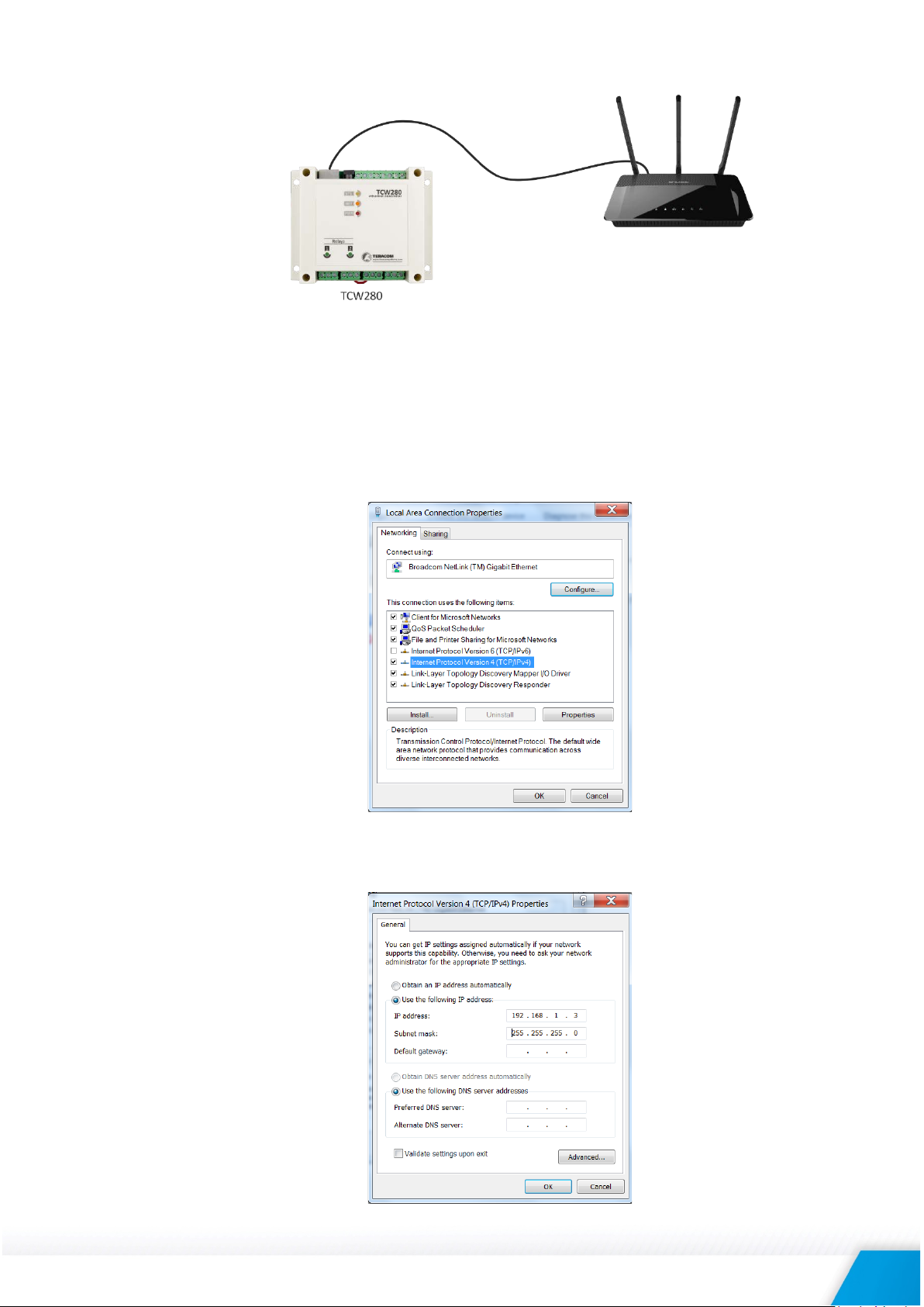
TCW280 can be used in a wireless network by connecting through a wireless router.
5.4. Communication setup
By default TCW280 is delivered with the following network settings:
IP address: 192.168.1.2, Subnet Mask: 255.255.255.0, Default Gateway: 192.168.1.1
Communication with TCW280 can be established by assigning a temporary IP address to the
computer. For computers with Windows OS assigning of IP address is made in “Local area connection
properties”:
This address should be on the same network - for example 192.168.1.3:
TCW280_R1.2 – February 2019 Page 9
Page 10
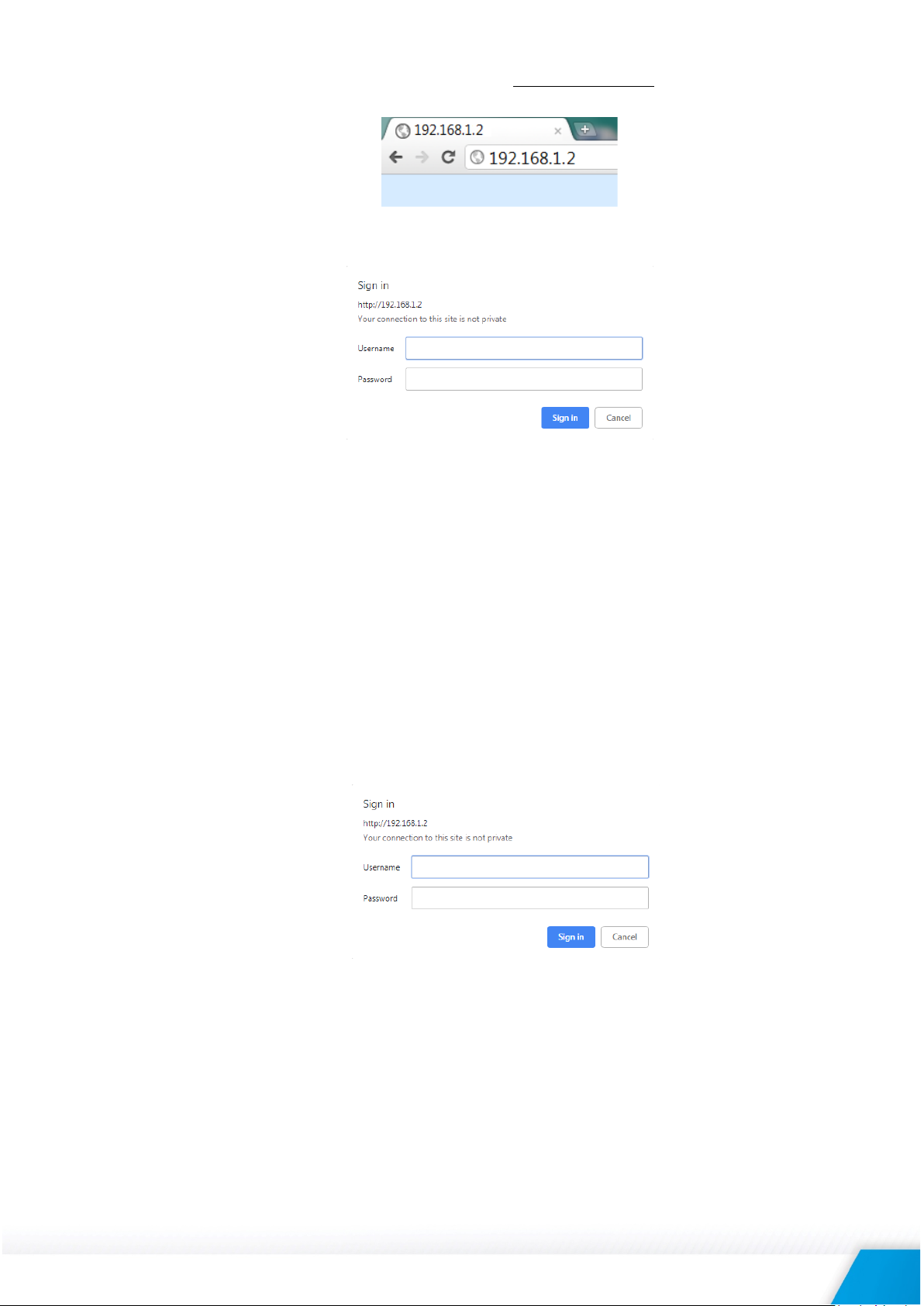
To get access to the web interface, you should type http://192.168.1.2 into the browser.
If the network settings are correct, the login pop-up window will appear:
All TCW controllers connected to LAN can be easily found by the free tool “TCW discoverer”.
It is available for Win and Mac operating systems and can be downloaded from
www.teracomsystems.com.
6. Web interface
The web interface allows configuration, monitoring, and control.
All pages are UTF-8 encoded.
If the controller is properly addressing, login pop-up window appears.
Authorization data must be entered (by default username=admin, password=admin).
It is recommended to change the username and password to prevent unauthorized access to the
controller.
The controller supports a few active session.
6.1. Monitoring
On this page can be monitored the temporary status of all outputs. There is a possibility to change
them.
The page consists of three sections - "Analog outputs", "Digital outputs" and "Relays". Each section
can be added/removed from the page for better observation. This is done by the "Setup->SystemDisplay".
For convenience in the footer of the page, there is system information for the product.
TCW280_R1.2 – February 2019 Page 10
Page 11
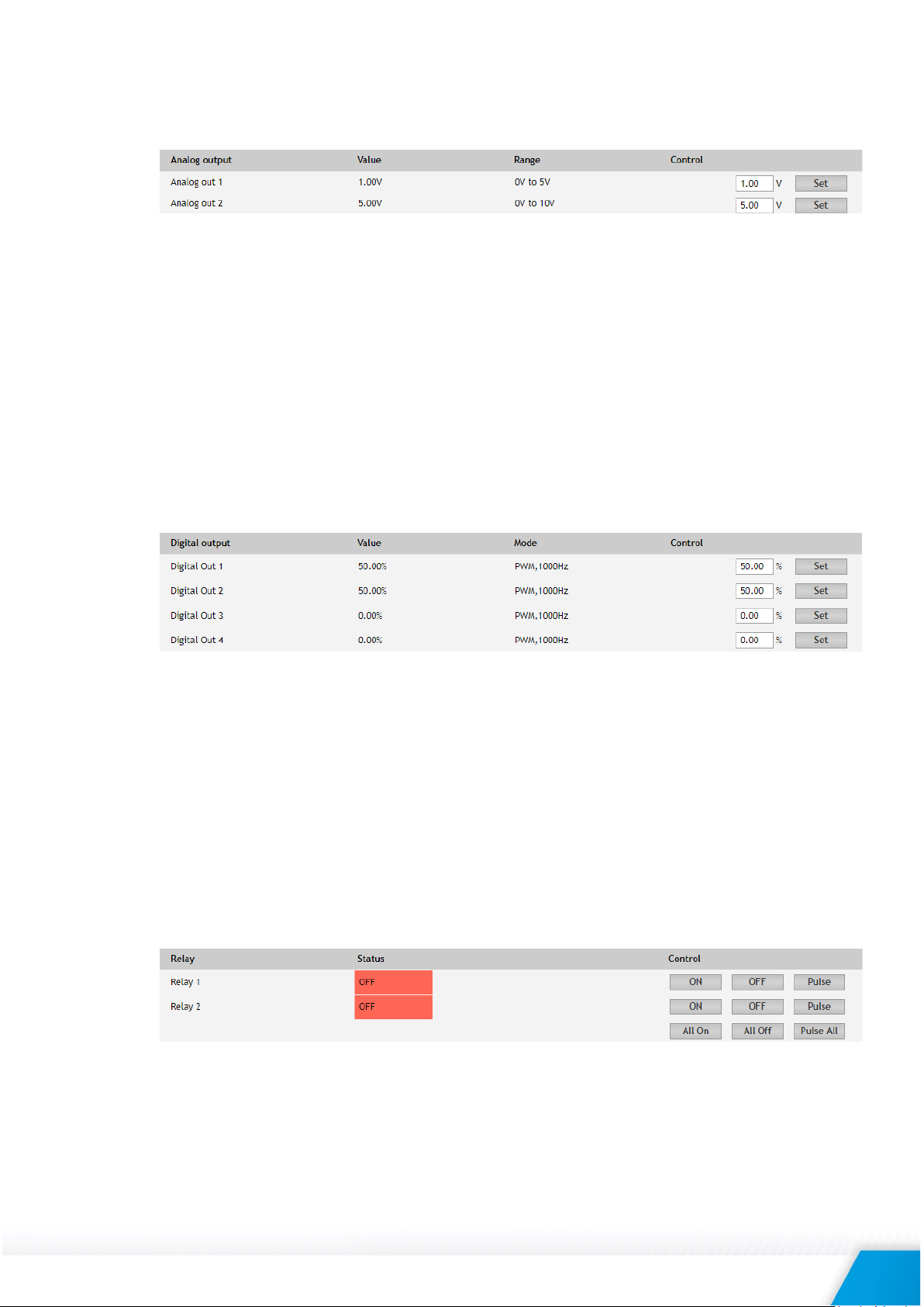
6.1.1. Analog outputs section
This section contains information about the current state of each analog output as well as its
operating range.
Entering a new value and pressing "Set" button changes the status of the output. There is
protection against entering values outside the selected range.
The selected output value is stored in non-volatile memory, and after a power-restore cycle, it is
automatically set. This is so unless in the "Setup-> Outputs" a specific value is selected that will
appear at the output when the power is turned on.
In "Setup-> Outputs" you can also change the description of each analog output, its operating
mode, and its operating range.
Besides through the WEB interface, the status of analog outputs can be changed by HTTP API,
SNMP, and MODBUS TCP/IP.
6.1.2. Digital outputs section
This section contains information about the current state of each digital output and its operating
mode.
The control section is different for both output modes. For PWM mode, there is protection against
entering invalid values. For ON/OFF mode there are activation buttons, similar to relay section.
The selected output value is stored in non-volatile memory, and after a power-restore cycle, it is
automatically set. This is so unless in the "Setup-> Outputs" a specific value is selected that will
appear at the output after the power is turned on.
In "Setup-> Outputs" you can change the description of each output and its mode of operation.
Besides through the WEB interface, the status of digital outputs can be changed by HTTP API,
SNMP, and MODBUS TCP/IP.
6.1.3. Relays section
This section contains information about the current state of the relays and buttons for their
control.
Each relay can be activated either remotely by WEB, SNMP, HTTP API, and MODBUS TCP/IP or
locally, from the status of assigned schedule.
For WEB control every relay has “On”, “Off” and “Pulse” buttons. There are also “All On”, “All Off”
and “Pulse All” for common control of relays. Pulse duration in seconds can be set separately for
each relay in “Setup->Outputs”.
TCW280_R1.2 – February 2019 Page 11
Page 12

For locally activated relays a text description of the controlling parameter is displayed rather than
buttons. The local relay activation can be set in “Setup->Outputs”.
6.2. Setup
6.2.1. Network
The network parameters are set on this page.
The controller supports static and dynamic IP addresses.
It is good practice to change the default IP address of the controller immediately after first poweron. This will avoid collisions if many devices are used on the same network.
It may be necessary to clear the arp cache, each time you connect a new device to the network.
This is done by typing arp -d in the command prompt window of the computer.
The “Hostname” is up to 15 characters. It is shown in the search results of TCW discoverer.
It is recommended to use public DNS server (8.8.8.8, 8.8.4.4 etc.) rather than the default gateway.
6.2.2. Outputs
On this page, descriptions and operating modes of each output can be set. After pressing "Save"
button, all changes are stored in non-volatile memory.
6.2.2.1. Analog outputs
For every analog output, a description up to 15 characters can be set. The description is used
to specify the output on Monitoring page and XML/JSON files.
Here you set the operating mode for each output, its operating range, and the value after power
on. By default, it is the last remembered one.
For current loop mode, in case of an open circuit, it is possible to send alarm messages (HTTP
Post or SNMP trap).
6.2.2.2. Digital outputs
For every digital output, a description up to 15 characters can be set. The description is used to
specify the output on Monitoring page and XML/JSON files.
TCW280_R1.2 – February 2019 Page 12
Page 13

Here you set the operating mode for each output, its operating range, and the value after power
on. By default, it is the last remembered one.
For PWM mode, the frequency can be selected from a drop-down menu, but it is the same for
all outputs.
For ON/OFF mode, the pulse duration can be different for every digital output. The pulse
duration can be in a range of 0.1 to 999999 seconds.
6.2.2.3. Relays
For every relay, a description up to 15 characters can be set. The description is used to specify
the relay on Monitoring page and XML/JSON files.
Here you can choose how the relay will be activated as well as its status after the power is
turned on. By default, it is the last remembered one.
The pulse duration can be different for every relay. It can be in a range of 0.1 to 999999 seconds.
6.2.3. System
On this page, some general settings can be made.
6.2.3.1. General
The information in this section serves to identify the device in M2M communication.
6.2.3.2. WEB access
In this section, WEB access authentication can be deactivated. By default, authentication details
are admin/admin. It is strongly recommended to change them in “Administration->User/Pass”.
HTTP port for WEB access can be changed. This is useful for some routers which don’t support
different outside/inside ports for port forwarding. By default HTTP port is 80.
6.2.3.3. HTTP API
In this section, HTTP API access authentication can be activated/deactivated. By default it is
active.
Authentication details are same as WEB access. The controller support two types of
authentication – see an explanation for HTTP API below.
TCW280_R1.2 – February 2019 Page 13
Page 14

6.2.3.4. Monitoring page automatic refresh
Monitoring page refresh interval can be set between 0 and 253 seconds. Zero means no
automatic refresh.
6.2.3.5. Display
All three sections on Monitoring page can be added/removed independently by appropriate
setup here.
6.2.4. Time
For proper operation of schedules, there is an internal real-time clock (RTC). It can be set either
manually or automatically.
For automatic clock synchronization, the controller supports NTP (Network Time Protocol) and all
necessary parameters for automatic synchronization are available in this section.
By default NTP synchronization is disabled, server – time.google.com, Time zone +00:00 and
interval of 12 hours.
It is strongly recommended to use time.google.com as a time server.
TCW280_R1.2 – February 2019 Page 14
Page 15

6.3. Services
6.3.1. Modbus
TCW280 supports Modbus TCP/IP.
By default Modbus is disabled. Standard port for this protocol is 502. More about this functionality
can be read at MODBUS section below.
6.3.2. SNMP
TCW280 supports SNMP v.2.
In this section, all necessary parameters for proper operation of SNMP can be set.
By default SNMP is disabled, the port is 161, read community is “public” and write community is
“private”.
In an alarm condition, SNMP trap can be sent up to 5 independent recipients. All they can be with
different port and community. There is an independent button for trap test.
SNMP traps can be sent:
• In case of an open circuit for analog output in current loop mode;
• After restart;
• After power on.
Actual MIB file can be downloaded from here.
TCW280_R1.2 – February 2019 Page 15
Page 16

6.3.3. HTTP Post
TCW280 can periodically upload a file to a dedicated server, using HTTP Post. The period of the
post is between 10 and 3600 seconds. The file format can be XML or JSON.
In addition to the periodical post, the file can be uploaded at any alarm condition. In this case
“Connect on any alarm” should be checked.
The HTTP Post can be sent simultaneously up to 3 different servers.
If “Process Answer” option is enabled, TCW280 will process the answer (command) of the chosen
server only. The list of valid commands is described in section HTTP API commands below.
The “Key” field value is sent in the XML/JSON and can be used for device identification.
6.3.4. Schedule
TCW280 supports four schedules. In every schedule, up to four different tasks can be set.
The schedules are useful for creating tasks that vary with calendar dates.
TCW280_R1.2 – February 2019 Page 16
Page 17

There are two types of schedule depending on repetition and duration:
• A single task for a time period:
With the above setting, there will be an event on 04.12.2018 starts at 10:00:00 and ends in
11:00:35.
The resolution for “OFF time” is 0.1 seconds, which gives a possibility for very short pulses
support.
• A weekly task for a time period:
With the above setting, there will be an event on Wednesdays, Fridays, and Saturdays
starting at 21:00:00 and ending in 22:25:20.
6.3.5. Dynamic DNS
With dynamic DNS, TCW280 can be accessed from the public Internet without investing in a
broadband account that has a static IP address.
TCW280 supports the following DNS services – DynDNS, No-IP, and DNS-O-Matric.
6.4. Administration
6.4.1. User/Pass
The TCW280 supports one user only. It has administrative rights.
The username and password can be up to 31 characters long.
6.4.2. Backup/Restore
The TCW280 supports backup and restore of all user setting. All settings are saved in XML backup
file. This file can be used after this for restore on many devices. This is very useful for multiplying
similar settings to a batch of controllers.
TCW280_R1.2 – February 2019 Page 17
Page 18
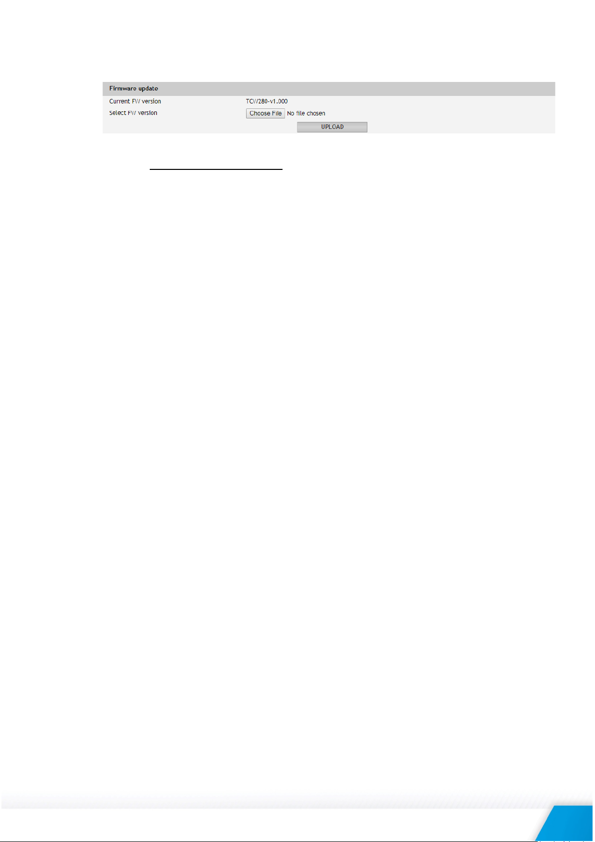
6.4.3. FW update
The TCW280 can be updated via a WEB interface.
To update the device follow the steps below:
• Go to www.teracomsystems.com and download the latest firmware;
• From Administration->FW update select downloaded .cod file and press “upload” button;
• After the firmware update is completed, the Login page will appear.
Attention! Don’t turn off the power supply during the update. Turning off the power supply will
damage the device.
6.5. Logout
The TCW280 support multisession, but the good practice is to log out after finishing the work.
TCW280_R1.2 – February 2019 Page 18
Page 19

7. Protocols and API
OID
Name
Access
Description
Syntax
x.2.1.1.0
name
read-only
Device name
DisplayString
x.2.1.2.0
version
read-only
Firmware version
DisplayString
x.2.1.3.0
dateTime
read-only
Date and time
DateAndTime
OID
Name
Access
Description
Syntax
x.2.2.1.1.0
deviceID
read-only
Device ID is Default MAC Address
MacAddress
x.2.2.1.2.0
hostName
read-only
Host Name
DisplayString
x. 2.2.1.3.0
deviceIP
read-only
Device IP Address
IpAddress
OID
Name
Access
Description
Syntax
x.2.2.2.1.1.1.0
anOut1description
read-write
Analog out 1 description
DisplayString
x.2.2.2.1.1.2.0
anOut1mode
read-write
Analog out 1 mode
Integer {
voltage(0),current(1)}
x.2.2.2.1.1.3.0
anOut1range
read-write
Analog out 1 range
Integer {
ma0to24(7)}
x.2.2.2.1.1.4.0
anOut1restvalue
read-write
Analog out 1 restart value
Integer {
ma22(13),ma24(14)}
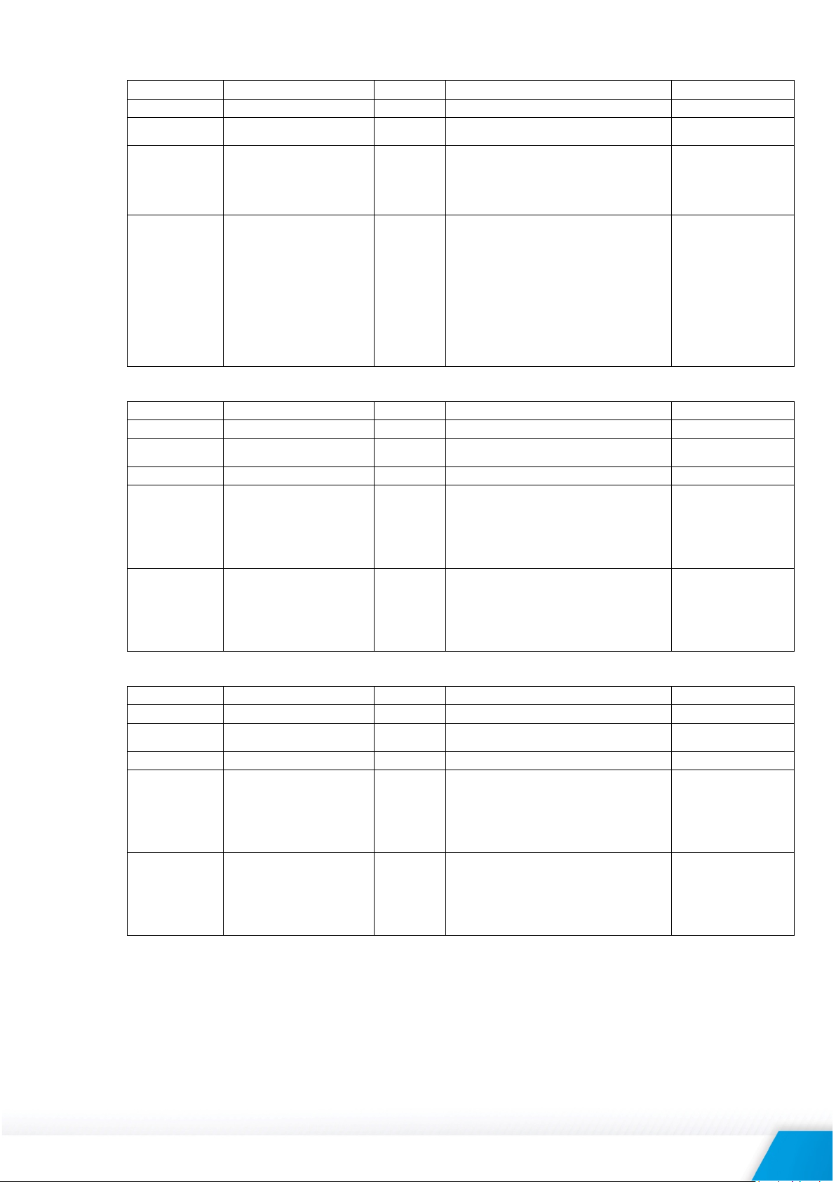
7.1. SNMP
Simple Network Management Protocol (SNMP) is a standard internet protocol for managing devices
on IP networks. In typical uses of SNMP, one or more administrative computers, called managers,
monitor and control devices on LAN. Each controlled device, at all times, executes a software
component called an agent which reports information via SNMP to the manager.
The TCW280 can be configured and monitored through SNMP.
This could be done using every SNMP v.2 compatible program. Parameters that can be changed, are
grouped according to their functions in the tables below. To obtain a valid OID number it is necessary
to replace the “x” symbol with ”1.3.6.1.4.1.38783”.
To save the changes configurationSaved (OID x.2.3.5.0) should be set to "1".
product
setup -> network
setup -> outputs -> anOutSetup -> anOut1Setup
volt0to5(0),volt0to10(1),
ma4to20(5),
ma0to20(6),
lastValue(0),volt0of5(1),
volthalfof5(2),
volt5of5(3),
volt0of10(4),
volt5to10(5),
volt10of10(6),ma0(7),
ma2(8), ma4(9),
ma10(10),
ma12(11),ma20(12),
TCW280_R1.2 – February 2019 Page 19
Page 20
setup -> outputs -> anOutSetup -> anOut2Setup
OID
Name
Access
Description
Syntax
x.2.2.2.1.2.1.0
anOut2description
read-write
Analog out 2 description
DisplayString
x.2.2.2.1.2.2.0
anOut2mode
read-write
Analog out 2 mode
Integer {
voltage(0),current(1)}
x.2.2.2.1.2.3.0
anOut2range
read-write
Analog out 2 range
Integer {
ma0to24(7)}
x.2.2.2.1.2.4.0
anOut2restvalue
read-write
Analog out 2 restart value
Integer {
ma22(13),ma24(14)}
OID
Name
Access
Description
Syntax
x.2.2.2.2.1.1.0
digOut1description
read-write
Digital Out 1 description
DisplayString
x.2.2.2.2.1.2.0
digOut1mode
read-write
Digital out 1 mode
Integer {
onoff(0),pwm(1)}
x.2.2.2.2.1.3.0
digOut1pulseWidth
read-write
Digital out 1 Pulse x100ms
Integer32
x.2.2.2.2.1.4.0
digOut1controlledBy
read-write
Digital out 1 control logic
Integer {
shedule4(4)}
x.2.2.2.2.1.5.0
digOut1reststate
read-write
Digital out 1 restart state
Integer {
percent100(5)}
OID
Name
Access
Description
Syntax
x.2.2.2.2.2.1.0
digOut2description
read-write
Digital out 2 description
DisplayString
x.2.2.2.2.2.2.0
digOut2mode
read-write
Digital out 2 mode
Integer {
onoff(0),pwm(1)}
x.2.2.2.2.2.3.0
digOut2pulseWidth
read-write
Digital out 2 Pulse x100ms
Integer32
x.2.2.2.2.2.4.0
digOut2controlledBy
read-write
Digital out 2 control logic
Integer {
shedule4(4)}
x.2.2.2.2.2.5.0
digOut2reststate
read-write
Digital out 2 restart state
Integer {
percent100(5)}
setup -> outputs -> digOutSetup-> digOut1Setup
volt0to5(0),volt0to10(1),
ma4to20(5),
ma0to20(6),
lastValue(0),volt0of5(1),
volthalfof5(2),
volt5of5(3),
volt0of10(4),
volt5to10(5),
volt10of10(6),ma0(7),
ma2(8), ma4(9),
ma10(10),
ma12(11),ma20(12),
setup -> outputs -> digOutSetup-> digOut2Setup
webORm2m(0),
shedule1(1),
shedule2(2),
shedule3(3),
lastState(0),
on(1),off(2),
percent0(3),
percent50(4),
webORm2m(0),
shedule1(1),
shedule2(2),
shedule3(3),
lastState(0),
on(1),off(2),
percent0(3),
percent50(4),
TCW280_R1.2 – February 2019 Page 20
Page 21

setup -> outputs -> digOutSetup-> digOut3Setup
OID
Name
Access
Description
Syntax
x.2.2.2.2.3.1.0
digOut3description
read-write
Digital out 3 description
DisplayString
x.2.2.2.2.3.2.0
digOut3mode
read-write
Digital out 3 mode
Integer {
onoff(0),pwm(1)}
x.2.2.2.2.3.3.0
digOut3pulseWidth
read-write
Digital out 3 Pulse x100ms
Integer32
x.2.2.2.2.3.4.0
digOut3controlledBy
read-write
Digital out 3 control logic
Integer {
shedule4(4)}
x.2.2.2.2.3.5.0
digOut3reststate
read-write
Digital out 3 restart state
Integer {
percent100(5)}
OID
Name
Access
Description
Syntax
x.2.2.2.2.4.1.0
digOut4description
read-write
Digital out 4 description
DisplayString
x.2.2.2.2.4.2.0
digOut4mode
read-write
Digital out 4 mode
Integer {
onoff(0),pwm(1)}
x.2.2.2.2.4.3.0
digOut4pulseWidth
read-write
Digital out 4 Pulse x100ms
Integer32
x.2.2.2.2.4.4.0
digOut4controlledBy
read-write
Digital out 4 control logic
Integer {
shedule4(4)}
x.2.2.2.2.4.5.0
digOut4reststate
read-write
Digital out 4 restart state
Integer {
percent100(5)}
OID
Name
Access
Description
Syntax
x.2.2.2.2.5.0
digOutpwmfreq
read-write
Digital outs pwm frequency
Integer {
hz2000(7)}
OID
Name
Access
Description
Syntax
x.2.2.2.3.1.1.0
relay1description
read-write
Relay 1 description
DisplayString
x.2.2.2.3.1.2.0
relay1pulseWidth
read-write
Relay 1 Pulse x100ms
Integer32
x.2.2.2.3.1.3.0
relay1controlledBy
read-write
Relay 1 control logic
Integer {
shedule4(4)}
x.2.2.2.3.1.4.0
relay1InitState
read-write
Relay 1 restart state
Integer {
lastState(0),on(1),off(2)}
setup -> outputs -> digOutSetup-> digOut4Setup
webORm2m(0),
shedule1(1),
shedule2(2),
shedule3(3),
lastState(0),
on(1),off(2),
percent0(3),
percent50(4),
webORm2m(0),
shedule1(1),
shedule2(2),
shedule3(3),
setup -> outputs -> digOutSetup
setup -> outputs -> relaysSetup-> relay1setup
lastState(0),
on(1),off(2),
percent0(3),
percent50(4),
hz1(0),hz5(1),hz10(2),
hz50(3),hz100(4),
hz500(5),hz1000(6),
webORm2m(0),
shedule1(1),
shedule2(2),
shedule3(3),
TCW280_R1.2 – February 2019 Page 21
Page 22

setup -> outputs -> relaysSetup-> relay1setup
OID
Name
Access
Description
Syntax
x.2.2.2.3.2.1.0
relay2description
read-write
Relay 2 description
DisplayString
x.2.2.2.3.2.2.0
relay2pulseWidth
read-write
Relay 2 Pulse x100ms
Integer32
x.2.2.2.3.2.3.0
relay2controlledBy
read-write
Relay 2 control logic
Integer {
shedule4(4)}
x.2.2.2.3.2.4.0
relay2InitState
read-write
Relay 2 restart state
Integer {
lastState(0),on(1),off(2)}
OID
Name
Access
Description
Syntax
x.2.3.1.1.1.0
anOut1Int
read-write
Analog out 1 x100 in Integer format
Integer32
x.2.3.1.1.2.0
anOut1Alarm
read-only
Analog out 1 alarm
integer {
tempioutfault(5)}
OID
Name
Access
Description
Syntax
x.2.3.1.2.1.0
anOut2Int
read-write
Analog out 2 x100 in Integer format
Integer32
x.2.3.1.2.2.0
anOut2Alarm
read-only
Analog out 2 alarm
integer {
tempioutfault(5)}
OID
Name
Access
Description
Syntax
x.2.3.2.1.1.0
digOut1Int
read-write
Digital out 1 x100 in Integer format
Integer32
x.2.3.2.1.2.0
digOut1State
read-write
Digital out 1 State
integer {off(0), on(1)}
x.2.3.2.1.3.0
digOut1Pulse
read-write
Digital out 1 Pulse
integer {off(0), on(1)}
OID
Name
Access
Description
Syntax
x.2.3.2.2.1.0
digOut2Int
read-write
Digital out 2 x100 in Integer format
Integer32
x.2.3.2.2.2.0
digOut2State
read-write
Digital out 2 State
integer {off(0), on(1)}
x.2.3.2.2.3.0
digOut2Pulse
read-write
Digital out 2 Pulse
integer {off(0), on(1)}
OID
Name
Access
Description
Syntax
x.2.3.2.3.1.0
digOut3Int
read-write
Digital out 3 x100 in Integer format
Integer32
x.2.3.2.3.2.0
digOut3State
read-write
Digital out 3 State
integer {off(0), on(1)}
x.2.3.2.3.3.0
digOut3Pulse
read-write
Digital out 3 Pulse
integer {off(0), on(1)}
OID
Name
Access
Description
Syntax
x.2.3.2.4.1.0
digOut4Int
read-write
Digital out 4 x100 in Integer format
Integer32
x.2.3.2.4.2.0
digOut4State
read-write
Digital out 4 State
integer {off(0), on(1)}
x.2.3.2.4.3.0
digOut4Pulse
read-write
Digital out 4 Pulse
integer {off(0), on(1)}
OID
Name
Access
Description
Syntax
x.2.3.3.1.1.0
relay1State
read-write
Relay 1 State
integer {off(0), on(1)}
x.2.3.3.1.2.0
relay1Pulse
read-write
Relay 1 Pulse
integer {off(0), on(1)}
monitorNcontrol -> anOut-> anOut1
monitorNcontrol -> anOut-> anOut2
webORm2m(0),
shedule1(1),
shedule2(2),
shedule3(3),
none(0), tempfault(1),
ioutfault(4),
none(0), tempfault(1),
ioutfault(4),
monitorNcontrol -> digOut-> digOut1
monitorNcontrol -> digOut-> digOut2
monitorNcontrol -> digOut-> digOut3
monitorNcontrol -> digOut-> digOut4
monitorNcontrol -> relays-> relay1
TCW280_R1.2 – February 2019 Page 22
Page 23

monitorNcontrol -> relays-> relay2
OID
Name
Access
Description
Syntax
x.2.3.3.2.1.0
Relay2State
read-write
Relay 2 State
integer {off(0), on(1)}
x.2.3.3.2.2.0
Relay2Pulse
read-write
Relay 2 Pulse
integer {off(0), on(1)}
OID
Name
Access
Description
Syntax
x.2.3.4.0
configurationSaved
read-write
Configuration save status SAVED/UNSAVED
integer {
unsaved(0), saved(1)}
x.2.3.5.0
restartDevice
read-write
Restart Device
integer {
cancel(0), restart(1)}
x.2.3.6.0
hardwareErr
read-only
Hardware Error
integer {
noErr(0), hwErr(1)}
monitorNcontrol
7.2. MODBUS TCP/IP
Modbus protocol is a serial communications protocol originally published by Modicon in 1979. It is
used to establish master-slave/client-server communication between intelligent devices. Modbus is
often used to connect a supervisory computer with a remote terminal unit (RTU) in supervisory
control and data acquisition (SCADA) systems.
7.2.1. Codes and answers
7.1.1.1. Read Coil Status (FC=01)
Request
This command is requesting the ON/OFF status of discrete coils on address 100.
01 0064 0001
01: Function Code 1 (read Coil Status)
0064: The Data Address of the coil to read ( 0064 hex = 100)
0001: The total number of coils requested. (01 hex = 1)
Response
01 01 01
01: Function Code 1 (read Coil Status)
01: The number of data bytes to follow
01: 7 space holders & Coils 1 (0000 0001)
Due to the number of coils requested, the last data field 01 contains the status of
only 1 coil. The 7 most significant bits in this data field are filled in with zeroes. The
activated relay is 1.
7.1.1.2. Force Single Coil (FC=05)
Request
This command is writing the contents of discrete on address 100 to ON.
05 0064 FF00
Response
The normal response is an echo of the query, returned after the coil has been written.
05 0064 FF00
TCW280_R1.2 – February 2019 Page 23
05: Function Code 5 (Force Single Coil)
0064: The Data Address of the coil. ( 0064 hex = 100)
FF00: The status to write ( FF00 = ON, 0000 = OFF )
05: Function Code 5 (Force Single Coil)
0064: The Data Address of the coil. (0064 hex = 100)
FF00: The status written ( FF00 = ON, 0000 = OFF )
Page 24

7.1.1.3. Read Holding Registers (FC=03)
Request
This command is requesting the content of holding registers 500.
03 01F4 0002
03: Function Code 3 (read Holding Registers)
0064: The Data Address of the first register requested (01F4 hex = 500)
0002: The total number of registers requested. (read 2 registers each 2 bytes = 4
bytes)
Response
03 04 3FA0 0000
03: Function Code 3 (read Analog Output Holding Registers)
04: The number of data bytes to follow (2 registers x 2 bytes each = 4 bytes)
3FA0 0000: 4 bytes value
All holding registers with float value are sent in big-endian.
In the example above, a value of 1.25 is sent.
Request
This command is requesting the content of holding registers 1000.
03 03E8 0020
03: Function Code 3 (read Holding Registers)
03E8: The Data Address of the first register requested (03E8 hex = 1000)
0020: The total number of registers requested (read 32 registers each 2 bytes = 64
bytes)
Response
03 40 5265 6C61 7920 3100 0000 0000 0000 0000 0000 0000 0000 0000 0000 0000 0000
0000 0000 0000 0000 0000 0000 0000 0000 0000 0000 0000 0000 0000 0000 0000 0000
0000
03: Function Code 3 (read Analog Output Holding Registers)
40: The number of data bytes to follow (32 registers x 2 bytes each = 64 bytes)
5265 6C61 7920 3100 0000 0000 0000 0000 0000 0000 0000 0000 0000 0000 0000
0000 0000 0000 0000 0000 0000 0000 0000 0000 0000 0000 0000 0000 0000 0000
0000 0000: 64 bytes value
All holding registers with strings are sent in big-endian.
The answer is padded with 0.
In the example above string “Relay 1” is sent.
7.1.1.4. Exception codes
All exceptions are signaled by adding 0x80 to the function code of the request, and
following this byte by a single reason byte for example as follows:
01 Illegal function
Function code received in the query is not an allowable action for the controller.
02 Illegal data address
The data address received in the query is not an allowable address for the slave.
More specifically, the combination of the reference number and the transfer
length is invalid. For a controller with 100 registers, a request with offset 96 and
length 4 would succeed, a request with offset 96 and length 5 will generate
exception 02.
TCW280_R1.2 – February 2019 Page 24
Page 25

7.2.2. Address table
Parameter
FC
Address
(Decimal)
Data size
Read Relay 1
01
100
Discrete
Read Relay 2
01
101
Discrete
Write Relay 1
05
100
Discrete
Write Relay 2
05
101
Discrete
Read Digital Out 1
01
102
Discrete
Read Digital Out 2
01
103
Discrete
Read Digital Out 3
01
104
Discrete
Read Digital Output 4
01
105
Discrete
Write Digital Out 1
05
102
Discrete
Write Digital Out 2
05
103
Discrete
Write Digital Out 3
05
104
Discrete
Write Digital Out 4
05
105
Discrete
Read Digital Out 1 PWM
03
200
32-bit Float
Read Digital Out 2 PWM
03
202
32-bit Float
Read Digital Out 3 PWM
03
204
32-bit Float
Read Digital Out 4 PWM
03
206
32-bit Float
Write Digital Out 1 PWM
16
200
32-bit Float
Write Digital Out 2 PWM
16
202
32-bit Float
Write Digital Out 3 PWM
16
204
32-bit Float
Write Digital Out 4 PWM
16
206
32-bit Float
Read Digital Mode Out 1
03
400
16-bit Unsigned integer
Read Digital Mode Out 2
03
401
16-bit Unsigned integer
Read Digital Mode Out 3
03
402
16-bit Unsigned integer
Read Digital Mode Out 4
03
403
16-bit Unsigned integer
Write Digital Mode Out 1
16
400
16-bit Unsigned integer
Write Digital Mode Out 2
16
401
16-bit Unsigned integer
Write Digital Mode Out 3
16
402
16-bit Unsigned integer
Write Digital Mode Out 4
16
403
16-bit Unsigned integer
Read Analog Out 1
03
500
32-bit Float
Read Analog Out 2
03
502
32-bit Float
Write Analog Out 1
16
500
32-bit Float
Write Analog Out 2
16
502
32-bit Float
Read Relay 1 Description
03
1000
64 bytes UTF-8
Read Relay 2 Description
03
1032
64 bytes UTF-8
Read Digital Out 1 Description
03
2000
64 bytes UTF-8
TCW280_R1.2 – February 2019 Page 25
Page 26
Read Digital Out 2 Description
03
2032
64 bytes UTF-8
Read Digital Out 3 Description
03
2064
64 bytes UTF-8
Read Digital Out 4 Description
03
2096
64 bytes UTF-8
Read Analog Out 1 Description
03
4000
64 bytes UTF-8
Read Analog Out 2 Description
03
4032
64 bytes UTF-8
7.3. HTTP API
7.3.1. HTTP Post
TCW280 can send HTTP Post to upload XML/JSON file to a dedicated server.
This functionality is very useful if the controller is behind the router without public IP address or
the user don’t have access to router configuration. The server should have a public IP address.
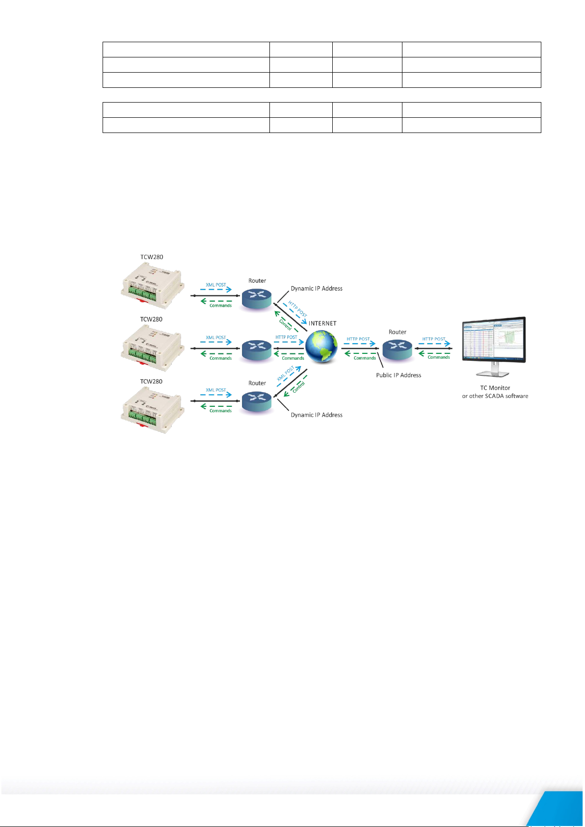
The typical monitoring application is shown in the picture below:
HTTP post can be sent periodically or periodically plus on an alarm condition. As an answer, the
server can send HTTP Get with appropriate command – see 7.3.3. HTTP commands
To test HTTP Post follow the steps below:
• Save following code like post.php:
<?php
define("FILENAME", 'status.xml');
define("FOLDER", '');
define("SEPARATOR", '');
define("STR_SUCCESS", 'set FIN');
define("STR_ERROR", 'error');
if($_SERVER['REQUEST_METHOD'] == 'POST'){
$datePrefix = date('YmdHis', strtotime('now'));
$pathname = FOLDER.SEPARATOR.$datePrefix.'_'.FILENAME;
$postdata = file_get_contents("php://input");
$handle = fopen($pathname, 'w+');
$content = var_export($postdata, true);
fwrite($handle, substr($content, 1, strlen($content)-2));
fclose($handle);
echo (($handle === false) ? STR_ERROR : STR_SUCCESS)."\r\n";
}
else {
echo "The PHP script is working!";
}
?>
• Copy the post.php file on a public web server with PHP support. To verify that the script is
working properly, you can type the URL ( for example www.yourserverURL.com/post.php )
in your web browser. If all is OK, a web page with “The PHP script is working!” will be
shown.
TCW280_R1.2 – February 2019 Page 26
Page 27

• Set the controller to send HTTP Post to your web server. Enter the address
XML/HTTP API authentication
Format
enabled
http://device.ip.address/status.xml?a=uuuu:pppp
disabled
http://device.ip.address/status.xml
Command
Description
ron=n
Turn relay n ON
ron=2 - turn ON relay 2
ron=1&ron=2
Turn both relays ON
rof=n
Turn relay n OFF
rof=2 - turn OFF relay 2
rof=1&rof=2
Turn both relays OFF
rtg=n
Toggle relay n state
rtg=1 - toggle relay 1 state
(yourserverURL.com/post.php) in the URL field. Click on “Test HTTP Post” button.
• If the HTTP POST is received and processed, “OK” will be shown close to the button. Along
with this, an XML file will be created in the same directory, where post.php is located. The
file name will contain time information and looks like 20181203103318_status.xml.
7.3.2. HTTP Get
HTTP Get can be used to monitor TCW280 via XML or JSON files. The format is as follows:
http://device.ip.address/status.xml
http://device.ip.address/status.json
See sections 7.3.4 XML file structure and 7.3.5 JSON file structure for details of files.
HTTP Get can be sent in anytime to TCW280 if it is on the same network or it has appropriate
routing.
If there isn’t direct access to the device, HTTP Get can be sent immediately after HTTP Post
receiving from the same device.
7.3.2.1. Commands
All command used with HTTP Post can be used also with HTTP Get. The right format is:
http://device.ip.address/status.xml?yyy=xxx
Where:
yyy is the command;
xxx is the parameter.
Example:
http://device.ip.address/status.xml?ron=1, will turn Relay 1 ON.
7.3.2.2. HTTP GET authentication
If HTTP API authentication is enabled, basic access authentication is required to access the
status.xml file. The format of the command is shown in the table below:
Example:
http://device.ip.address/status.xml?a=admin:admin&pper=120 will set post period on 120 sec
in case the username=admin and pass=admin
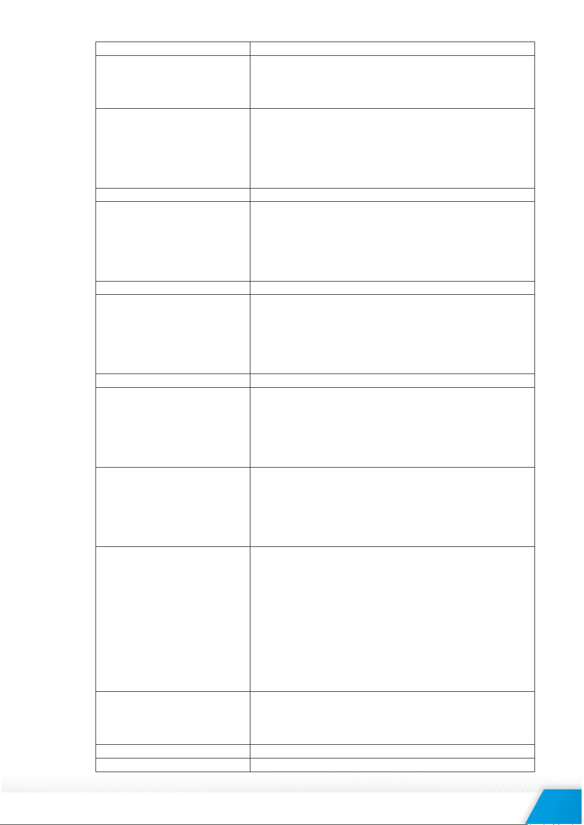
8.1.1. List of HTTP API commands
(n is 1 or 2 for the respective relay)
ron=1 - turn ON relay 1
TCW280_R1.2 – February 2019 Page 27
(n is 1 or 2 for the respective relay)
rof=1 - turn OFF relay 1
(n is 1 or 2 for the respective relay)
Page 28
rtg=2 - toggle relay 2 state
rpl=n
Pulse relay n
(n is 1 or 2 for the respective relay)
rpl=2 – pulse relay 2
don=n
Turn digital out n ON
don=8 – digital out 4 ON
don=1&don=2&don=4&don=8
Turn four Digital outs ON
dof=n
Turn digital out n OFF
dof=8 – digital out 4 OFF
dof=1&dof=2&dof=4&dof=8
Turn four Digital outs OFF
dtg=n
Toggle digital out n state
dtg=8 – toggle digital out 4 state
dtg=1&dtg=2&dtg=4&dtg=8
Toggle four digital outs
dpl=1
Pulse digital out n
dpl=8 – pulse digital out 4
docn=xx.x
Set PWM duty on Digital out n with xx.x%
doc4=20.0 – set 20.0% PWM duty Digital out 4
domn=x
Set mode Digital out n
dom4=1 - Set PWM mode Digital out 4
aocn=xx.xx
Set value xx.xx on Analog out n
aoc2=10.0 - Set value 10.0 on Analog out 2
pper=300
Set http post period 300 sec
FIN
Terminate session (it makes sense only for HTTP Post)
rpl=1 – pulse relay 1
(n is 1,2,4 or 8)
don=1 – digital out 1 ON
don=2 – digital out 2 ON
don=4 – digital out 3 ON
(n is 1,2,4 or 8)
dof=1 – digital out 1 OFF
dof=2 – digital out 2 OFF
dof=4 – digital out 3 OFF
(n is 1,2,4 or 8)
dtg=1 – toggle digital out 1 state
dtg=2 – toggle digital out 2 state
dtg=4 – toggle digital out 3 state
(n is 1,2,4 or 8)
dpl=1 – pulse digital out 1
dpl=2 – pulse digital out 2
dpl=4 – pulse digital out 3
(n is 1,2,3 or 4 for the respective digital out)
doc1=50.0 – set 50.0% PWM duty Digital out 1
doc2=40.0 – set 40.0% PWM duty Digital out 2
doc3=30.0 – set 30.0% PWM duty Digital out 3
(n is 1,2,3 or 4 for the respective digital out,
x=0 – ON/OFF mode, x=1 – PWM mode)
dom1=0 - Set ON/OFF mode Digital out 1
dom2=0 - Set ON/OFF mode Digital out 2
dom3=0 - Set ON/OFF mode Digital out 3
dom4=0 - Set ON/OFF mode Digital out 4
dom1=1 - Set PWM mode Digital out 1
dom2=1 - Set PWM mode Digital out 2
dom3=1 - Set PWM mode Digital out 3
TCW280_R1.2 – February 2019 Page 28
(n is 1 or 2 for the respective analog out)
aoc1=4.50 - Set value 4.50 on Analog out 1
Page 29

7.3.3. XML file structure
This XML file does not appear to have any style information associated with it. The document tree
is shown below.
<Monitor>
<DeviceInfo>
<DeviceName>TCW280</DeviceName>
<HostName>TCW280</HostName>
<ID>54:10:EC:7F:C4:90</ID>
<FwVer>TCW280-v1.000</FwVer>
<MnfInfo>www.teracomsystems.com</MnfInfo>
<SysContact>[email protected]</SysContact>
<SysName>SysName</SysName>
<SysLocation>SysLocation</SysLocation>
</DeviceInfo>
<AO>
<AO1>
<description>DAC out 1</description>
<value>4.00</value>
<unit>V</unit>
<range>0V to 5V</range>
<alarmState/>
<alarm>0< /alarm>
</AO1>
<AO2>
<description>DAC out 2</description>
<value>5.00</value>
<unit>V</unit>
<range>0V to 5V</range>
<alarmState/>
<alarm>0</alarm>
</AO2>
</AO>
<DO>
<DO1>
<description>Digital Out 1</description>
<value>50.00</value>
<unit>%</unit>
<valuebin/>
<pulseWidth>6.0</pulseWidth>
<mode>PWM,2000Hz</mode>
<control>0</control>
</DO1>
<DO2>
<description>Digital Out 2</description>
<value>OFF</value>
<unit/>
<valuebin>0</valuebin>
<pulseWidth>7.0</pulseWidth>
<mode>ON/OFF</mode>
<control>0</control>
</DO2>
<DO3>
<description>Digital Out 3</description>
<value>OFF</value>
<unit/>
<valuebin>0</valuebin>
<pulseWidth>8.0</pulseWidth>
<mode>ON/OFF</mode>
<control>0</control>
</DO3>
<DO4>
<description>Digital Out 4</description>
<value>OFF</value>
<unit/>
<valuebin>0</valuebin>
<pulseWidth>9.0</pulseWidth>
<mode>ON/OFF</mode>
<control>0</control>
</DO4>
</DO>
<R>
<R1>
TCW280_R1.2 – February 2019 Page 29
Page 30

<description>Relay 1</description>
<value>OFF</value>
<valuebin>0</valuebin>
<pulseWidth>1.0</pulseWidth>
<control>0</control>
</R1>
<R2>
<description>Relay 2</description>
<value>OFF</value>
<valuebin>0</valuebin>
<pulseWidth>2.0</pulseWidth>
<control>0</control>
</R2>
</R>
<HTTPPush>
<Key/>
<PushPeriod>300</PushPeriod>
</HTTPPush>
<hwerr/>
<Alarmed>0</Alarmed>
<Time>
<Date>05.12.2018</Date>
<Time>08:45:32</Time>
</Time>
</Monitor>
Where:
<alarm>1</alarm> means there is trigger condition.
7.3.4. JSON file structure
{
"Monitor": {
"DeviceInfo": {
"DeviceName": "TCW280",
"HostName": "TCW280",
"ID": "54:10:EC:7F:C4:90",
"FwVer": "TCW280-v1.000",
"MnfInfo": "www.teracomsystems.com",
"SysContact": "[email protected]",
"SysName": "SysName",
"SysLocation": "SysLocation"
},
"AO": {
"AO1": {
"description": "DAC out 1",
"value": "4.00",
"unit": "V",
"range": "0V to 5V",
"alarmState": "",
"alarm": "0"
},
"AO2": {
"description": "DAC out 2",
"value": "5.00",
"unit": "V",
"range": "0V to 5V",
"alarmState": "",
"alarm": "0"
}
},
"DO": {
"DO1": {
"description": "Digital Out 1",
"value": "50.00",
"unit": "%",
"valuebin": "",
"pulseWidth": "6.0",
"mode": "PWM,2000Hz",
"control": "0"
},
"DO2": {
"description": "Digital Out 2",
"value": "OFF",
"unit": "",
"valuebin": "0",
"pulseWidth": "7.0",
TCW280_R1.2 – February 2019 Page 30
Page 31

"mode": "ON\/OFF",
"control": "0"
},
"DO3": {
"description": "Digital Out 3",
"value": "OFF",
"unit": "",
"valuebin": "0",
"pulseWidth": "8.0",
"mode": "ON\/OFF",
"control": "0"
},
"DO4": {
"description": "Digital Out 4",
"value": "OFF",
"unit": "",
"valuebin": "0",
"pulseWidth": "9.0",
"mode": "ON\/OFF",
"control": "0"
}
},
"R": {
"R1": {
"description": "Relay 1",
"value": "OFF",
"valuebin": "0",
"pulseWidth": "1.0",
"control": "0"
},
"R2": {
"description": "Relay 2",
"value": "OFF",
"valuebin": "0",
"pulseWidth": "2.0",
"control": "0"
}
},
"HTTPPush": {
"Key": "",
"PushPeriod": "300"
},
"hwerr": "",
"Alarmed": "0",
"Time": {
"Date": "05.12.2018",
"Time": "10:18:39"
}
}
}
TCW280_R1.2 – February 2019 Page 31
Page 32

8. Factory default settings
Username
admin
Password
admin
IP Address
192.168.1.2
Subnet Mask
255.255.255.0
Default Gateway
192.168.1.1
SNMPConfiguration
disabled
readCommunity
public
writeCommunity
private
Analog outputs mode
Voltage
Analog outputs range
0V to 10V
Digital outputs mode
ON/OFF
Digital outputs
OFF
Relay outputs
OFF
TCW280 can be restored to its original factory default settings in 3 different ways.
8.1. Factory default from the WEB interface
If the button “Factory default” from Administration->Backup/Restore is pressed, all parameters
return to factory default except Network settings.
8.2. Factory default with the reset button
If the reset button is pressed for more than 5 seconds, while the device is working, all Network
settings go to factory default.
8.3. General factory default with the reset button
For factory default reset of all parameters following steps should be executed:
• Press and hold the RESET button, then turn on the power supply;
• Yellow LED shines and red LED blinks about 5 times on а second;
• After about 5 seconds red LED will turn off, the button can be released;
• Yellow LED flashes on 1 second and red LED shines – the device is in working mode, with
factory default settings.
The factory default settings are:
TCW280_R1.2 – February 2019 Page 32
Page 33

9. Environment information
This equipment is intended for use in a Pollution Degree 2 environment, at altitudes up to 2000 meters.
When the controller is a part of a system, the other elements of the system shall comply with the EMC
requirements and shall be intended for use in the same ambient conditions.
10. Safety
This device must not be used for medical, life-saving purposes or for any purpose where its failure could
cause serious injury or the loss of life.
To reduce the risk of fire, only flexible stranded wire, with cross section 0.5mm² or larger for wiring of
digital and analog inputs and relay output of the device should be used.
To avoid electric shock and fire hazard, do not expose this product to liquids, rain, or moisture. Objects
filled with liquids, such as vases, should not be placed on this device.
There is a risk of overheating (damage) of the controller if recommended free spaces to adjacent devices
are not ensured. The joint part with external component shall have space for attachment/removal of
the cable after installation.
Teracom does not guarantee successful operation of the product if the product was used under
conditions deviating from the product specifications.
To ensure that the device works correctly follow the steps below:
• Ensure that the device is installed correctly, refer to this user manual;
• Log into the devices via browser program;
• Go to Monitoring page. Press “All Off” and after this “All On” buttons in relay section;
• Both relays should be activated – their LED’s should shine. At the same time flashing “STS”
led should indicate the proper operation.
If the equipment is used in a manner not specified by the manufacturer, the protection provided by the
equipment may be impaired.
In no event will Teracom Ltd. be responsible or liable for indirect or consequential damages resulting
from the use or application of this equipment.
11. Maintenance
Upon completion of any service or repairs to the device or once per year, a safety check must be
performed to determine that this product is in proper operating condition.
Clean the device only with dry cloth. Do not use a liquid cleaner or an aerosol cleaner. Do not use a
magnetic/static cleaning device (dust remover) or any kind of abrasive materials to clean the device.
Appendix A
TCW280_R1.2 – February 2019 Page 33
Page 34

Fig.1
Fig.2
TCW280_R1.2 – February 2019 Page 34
 Loading...